EP1156199A2 - Controlled auto-ignition lean burn stratified engine by intelligent injection - Google Patents
Controlled auto-ignition lean burn stratified engine by intelligent injection Download PDFInfo
- Publication number
- EP1156199A2 EP1156199A2 EP01111563A EP01111563A EP1156199A2 EP 1156199 A2 EP1156199 A2 EP 1156199A2 EP 01111563 A EP01111563 A EP 01111563A EP 01111563 A EP01111563 A EP 01111563A EP 1156199 A2 EP1156199 A2 EP 1156199A2
- Authority
- EP
- European Patent Office
- Prior art keywords
- combustion chamber
- injection
- engine
- exhaust gas
- fuel
- Prior art date
- Legal status (The legal status is an assumption and is not a legal conclusion. Google has not performed a legal analysis and makes no representation as to the accuracy of the status listed.)
- Granted
Links
Images











Classifications
-
- F—MECHANICAL ENGINEERING; LIGHTING; HEATING; WEAPONS; BLASTING
- F02—COMBUSTION ENGINES; HOT-GAS OR COMBUSTION-PRODUCT ENGINE PLANTS
- F02D—CONTROLLING COMBUSTION ENGINES
- F02D13/00—Controlling the engine output power by varying inlet or exhaust valve operating characteristics, e.g. timing
- F02D13/02—Controlling the engine output power by varying inlet or exhaust valve operating characteristics, e.g. timing during engine operation
- F02D13/0203—Variable control of intake and exhaust valves
- F02D13/0215—Variable control of intake and exhaust valves changing the valve timing only
-
- F—MECHANICAL ENGINEERING; LIGHTING; HEATING; WEAPONS; BLASTING
- F02—COMBUSTION ENGINES; HOT-GAS OR COMBUSTION-PRODUCT ENGINE PLANTS
- F02B—INTERNAL-COMBUSTION PISTON ENGINES; COMBUSTION ENGINES IN GENERAL
- F02B1/00—Engines characterised by fuel-air mixture compression
- F02B1/12—Engines characterised by fuel-air mixture compression with compression ignition
-
- F—MECHANICAL ENGINEERING; LIGHTING; HEATING; WEAPONS; BLASTING
- F02—COMBUSTION ENGINES; HOT-GAS OR COMBUSTION-PRODUCT ENGINE PLANTS
- F02B—INTERNAL-COMBUSTION PISTON ENGINES; COMBUSTION ENGINES IN GENERAL
- F02B17/00—Engines characterised by means for effecting stratification of charge in cylinders
- F02B17/005—Engines characterised by means for effecting stratification of charge in cylinders having direct injection in the combustion chamber
-
- F—MECHANICAL ENGINEERING; LIGHTING; HEATING; WEAPONS; BLASTING
- F02—COMBUSTION ENGINES; HOT-GAS OR COMBUSTION-PRODUCT ENGINE PLANTS
- F02D—CONTROLLING COMBUSTION ENGINES
- F02D13/00—Controlling the engine output power by varying inlet or exhaust valve operating characteristics, e.g. timing
- F02D13/02—Controlling the engine output power by varying inlet or exhaust valve operating characteristics, e.g. timing during engine operation
- F02D13/0261—Controlling the valve overlap
- F02D13/0265—Negative valve overlap for temporarily storing residual gas in the cylinder
-
- F—MECHANICAL ENGINEERING; LIGHTING; HEATING; WEAPONS; BLASTING
- F02—COMBUSTION ENGINES; HOT-GAS OR COMBUSTION-PRODUCT ENGINE PLANTS
- F02D—CONTROLLING COMBUSTION ENGINES
- F02D13/00—Controlling the engine output power by varying inlet or exhaust valve operating characteristics, e.g. timing
- F02D13/02—Controlling the engine output power by varying inlet or exhaust valve operating characteristics, e.g. timing during engine operation
- F02D13/0269—Controlling the valves to perform a Miller-Atkinson cycle
-
- F—MECHANICAL ENGINEERING; LIGHTING; HEATING; WEAPONS; BLASTING
- F02—COMBUSTION ENGINES; HOT-GAS OR COMBUSTION-PRODUCT ENGINE PLANTS
- F02D—CONTROLLING COMBUSTION ENGINES
- F02D21/00—Controlling engines characterised by their being supplied with non-airborne oxygen or other non-fuel gas
- F02D21/06—Controlling engines characterised by their being supplied with non-airborne oxygen or other non-fuel gas peculiar to engines having other non-fuel gas added to combustion air
- F02D21/08—Controlling engines characterised by their being supplied with non-airborne oxygen or other non-fuel gas peculiar to engines having other non-fuel gas added to combustion air the other gas being the exhaust gas of engine
-
- F—MECHANICAL ENGINEERING; LIGHTING; HEATING; WEAPONS; BLASTING
- F02—COMBUSTION ENGINES; HOT-GAS OR COMBUSTION-PRODUCT ENGINE PLANTS
- F02D—CONTROLLING COMBUSTION ENGINES
- F02D41/00—Electrical control of supply of combustible mixture or its constituents
- F02D41/30—Controlling fuel injection
- F02D41/3011—Controlling fuel injection according to or using specific or several modes of combustion
- F02D41/3017—Controlling fuel injection according to or using specific or several modes of combustion characterised by the mode(s) being used
- F02D41/3035—Controlling fuel injection according to or using specific or several modes of combustion characterised by the mode(s) being used a mode being the premixed charge compression-ignition mode
- F02D41/3041—Controlling fuel injection according to or using specific or several modes of combustion characterised by the mode(s) being used a mode being the premixed charge compression-ignition mode with means for triggering compression ignition, e.g. spark plug
- F02D41/3047—Controlling fuel injection according to or using specific or several modes of combustion characterised by the mode(s) being used a mode being the premixed charge compression-ignition mode with means for triggering compression ignition, e.g. spark plug said means being a secondary injection of fuel
-
- F—MECHANICAL ENGINEERING; LIGHTING; HEATING; WEAPONS; BLASTING
- F02—COMBUSTION ENGINES; HOT-GAS OR COMBUSTION-PRODUCT ENGINE PLANTS
- F02B—INTERNAL-COMBUSTION PISTON ENGINES; COMBUSTION ENGINES IN GENERAL
- F02B23/00—Other engines characterised by special shape or construction of combustion chambers to improve operation
- F02B23/08—Other engines characterised by special shape or construction of combustion chambers to improve operation with positive ignition
- F02B23/10—Other engines characterised by special shape or construction of combustion chambers to improve operation with positive ignition with separate admission of air and fuel into cylinder
- F02B23/101—Other engines characterised by special shape or construction of combustion chambers to improve operation with positive ignition with separate admission of air and fuel into cylinder the injector being placed on or close to the cylinder centre axis, e.g. with mixture formation using spray guided concepts
-
- F—MECHANICAL ENGINEERING; LIGHTING; HEATING; WEAPONS; BLASTING
- F02—COMBUSTION ENGINES; HOT-GAS OR COMBUSTION-PRODUCT ENGINE PLANTS
- F02M—SUPPLYING COMBUSTION ENGINES IN GENERAL WITH COMBUSTIBLE MIXTURES OR CONSTITUENTS THEREOF
- F02M26/00—Engine-pertinent apparatus for adding exhaust gases to combustion-air, main fuel or fuel-air mixture, e.g. by exhaust gas recirculation [EGR] systems
- F02M26/01—Internal exhaust gas recirculation, i.e. wherein the residual exhaust gases are trapped in the cylinder or pushed back from the intake or the exhaust manifold into the combustion chamber without the use of additional passages
-
- Y—GENERAL TAGGING OF NEW TECHNOLOGICAL DEVELOPMENTS; GENERAL TAGGING OF CROSS-SECTIONAL TECHNOLOGIES SPANNING OVER SEVERAL SECTIONS OF THE IPC; TECHNICAL SUBJECTS COVERED BY FORMER USPC CROSS-REFERENCE ART COLLECTIONS [XRACs] AND DIGESTS
- Y02—TECHNOLOGIES OR APPLICATIONS FOR MITIGATION OR ADAPTATION AGAINST CLIMATE CHANGE
- Y02T—CLIMATE CHANGE MITIGATION TECHNOLOGIES RELATED TO TRANSPORTATION
- Y02T10/00—Road transport of goods or passengers
- Y02T10/10—Internal combustion engine [ICE] based vehicles
- Y02T10/12—Improving ICE efficiencies
Definitions
- the present invention relates to a lean burn internal combustion engine.
- lean burn is known to give enhanced thermal efficiency by reducing pumping losses and increasing ratio of specific heats.
- lean burn is known to give low fuel consumption and low NOx emissions.
- Known methods to extend the lean limit include improving ignitability of the mixture by enhancing the fuel preparation, for example using atomized fuel or vaporized fuel, and increasing the flame speed by introducing charge motion and turbulence in the air/fuel mixture.
- combustion by auto-ignition has been proposed for operating an engine with very lean air/fuel mixtures.
- the range of engine speeds and loads in which controlled auto-ignition combustion can be achieved is relatively narrow.
- the fuel used also has a significant effect on the operating range, for example, diesel fuel and methanol fuel have wider auto-ignition ranges than gasoline fuel.
- JP-A 10-266878 discloses a technique to accomplish auto-ignition of gasoline fuel over a predetermined load range from light load to high load by adjusting closing timing of an exhaust valve as well as opening and closing timings of an intake valve.
- an opening timing of the exhaust valve is held invariable at a crank position before a bottom dead center (BDC) position of expansion stroke against variations of load request, but a closing timing of the exhaust valve is adjusted to varying crank positions before a top dead center (TDC) position of exhaust stroke against varying load request.
- a throttle valve is fully opened over this predetermined load range.
- the closing timing of the exhaust valve advances as load request becomes low to increase the amount of exhaust gas remaining in a cylinder to decrease the amount of fresh charge.
- the opening timing of the intake valve is adjusted to varying crank positions after the TDC position of exhaust stroke against varying load request over the predetermined load range.
- the opening timing of the intake valve retards as load request becomes low.
- the closing timing of the intake valve is adjusted to varying crank positions after a bottom dead center (BDC) position of intake stroke against varying load request over the predetermined load range.
- BDC bottom dead center
- the closing timing of the intake valve retards gradually as load request becomes high over a portion of the predetermined load range and then advances gradually as load request becomes high over the remaining portion of the predetermined load range.
- closing timing of the exhaust valve controls the amount of exhaust gas in the cylinder, thereby controlling available combustion chamber volume for receiving fuel mixture thereby controlling load.
- closing timing of the intake valve advances during operation with load where auto-ignition is difficult to accomplish. Advancing closing timing of intake valve increases a compression ratio thereby increasing temperature of the mixture in the cylinder.
- US-A 6,135,088, which corresponds to JP-A 11-182246, shows a controlled auto-ignition engine operating process. According to this process, exhaust gas recirculated from an exhaust port through an EGR pipe is admitted to the combustion chamber, and thereafter a mixture of air and fuel is admitted through an intake port into the combustion chamber at a start of compression phase of the combustion chamber. Admission of the air fuel mixture produces stratification between the mixture and the exhaust gas to provide favorable conditions for auto-ignition within the combustion chamber.
- the exhaust gas is used to elevate the temperature of the air and fuel mixture admitted into the combustion chamber to assist in establishing favorable condition for auto-ignition around top dead center of piston compression stroke.
- An object of the present invention is to widen auto-ignition range of a lean burn internal combustion engine.
- a lean burn internal combustion engine having at least one cylinder with a piston reciprocating therein to define a combustion chamber.
- the engine comprises:
- FIG. 1 provides a block diagram of a system or method for widening auto-ignition range of a lean burn internal combustion engine.
- System 10 includes an internal combustion engine, indicated generally by reference numeral 12, in communication with an engine controller 14.
- FIG. 1 the area of a combustion chamber of engine 12 is shown.
- Engine 12 has at least one cylinder 16 with a piston 18 reciprocating therein to define a combustion chamber 20.
- Combustion chamber 20 is shown communicating within intake manifold 22 and exhaust manifold 24 via intake and exhaust valves 26 and 28, which are actuated by variable valve controllers 30 and 32.
- Fuel injector 34 of a fuel injection system is shown directly communicating with the combustion chamber 20 for direct injection of gasoline fuel into combustion chamber 20.
- a throttle 35 is used to throttle air for spark ignition combustion mode, but it is fully opened for auto-ignition combustion mode.
- An inlet control device 36 controls flow into combustion chamber 20.
- An outlet control device 38 controls flow from combustion chamber 20.
- inlet control device 36 includes at least one intake valve 26 actuated by valve controller 30, and outlet control device 38 includes at least one exhaust valve 28 actuated by valve controller 32.
- inlet control device 36 includes at least one intake valve 26 actuated by valve controller 30, and outlet control device 38 includes at least one exhaust valve 28 actuated by valve controller 32.
- Various sensors are provided to assist in accomplishing auto-ignition at appropriate ignition point over wide range of engine speed and load.
- Various sensors may include an intake air pressure sensor 48, which provides a signal indicative of intake air pressure (P0) in one embodiment.
- an exhaust gas temperature sensor 44 is used to determine a burnt or exhaust gas rate, that is a ratio of burnt or exhaust gas content of combustion chamber 20 to total of burnt or exhaust gas content and air content. Exhaust gas temperature sensor 44 provides a signal indicative of exhaust gas from combustion chamber 20.
- Engine 12 may include various other sensors such as an engine speed sensor to provide a signal indicative of engine speed (RPM), a crank angle sensor 54 to provide a signal indicative of crank angle ( ⁇ ), a pedal position sensor 50 to provide a signal indicative of the opening angle (APO) of an accelerator pedal 52, and the like.
- Accelerator pedal 52 is used to determine the driver demand, which, in turn, is used, as a load request, in the calculation of fuel quantity for injection.
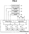
- engine controller 14 receives signals from the various sensors via input ports 60, which may provide signal conditioning, conversion, and/or fault detection, as well known in the art.
- Input ports 60 communicate with processor 62 via a data/control bus 64.
- Processor 62 implements control logic in the form of hardware and/or software instructions, which may be stored in computer readable storage medium 66, to effect control of engine 12.
- Computer readable storage medium 66 may include various types of volatile or nonvolatile memory such as random-access memory (RAM) 68, read-only memory (ROM) 70, and keep-alive memory (KAM) 72. These "functional" classifications of memory may be implemented by one or more different physical devices such as PROMs, EPROMs, EEPROMs, flash memory, and the like, depending upon the particular application.
- processor 62 executes instructions stored in computer readable storage medium 66 to carry out the method for widening auto-ignition range of engine 12 to communicate with various actuators of engine 12 via output ports 74.
- Actuators may control ignition timing or spark 76, fuel injection timing and fuel quantity for injection 78, valve timing of inlet control device 36, and valve timing of outlet control device 38.
- Characteristic engine diagrams for auto-ignition combustion mode and spark-ignition combustion mode are stored in controller 14 in the form of valve timings of inlet and outlet control devices 36 and 38 as well as for controlling the fuel injection for auto-ignition combustion and for controlling the fuel injection and ignition timing for spark-ignition combustion.
- Figure 3 provides a valve timing diagram illustrating a representative example of valve timings of inlet and outlet control devices 36 and 38 (intake and exhaust valves 26 and 28) for spark-ignition combustion mode at full or near full load.
- controller 14 transmits timings to outlet and inlet control devices 38 and 36 to provide optimum valve overlap duration around top dead center (TDC) of exhaust stroke of piston 18.
- TDC top dead center
- Figure 4 provides a valve timing diagram illustrating valve timings of inlet and outlet control devices 36 and 38 (intake and exhaust valves 26 and 28) for auto-ignition combustion mode.
- exhaust valve 28 of outlet control device 38 is allowed to close before piston 18 reaches the TDC of the exhaust stroke, so that high temperature exhaust gas is retained and compressed in cylinder 16 during the last travel section of the piston exhaust stroke.
- Intake valve 26 of inlet control device 36 is opened after the TDC position of the exhaust stroke. Setting of opening timing is such that inlet control device 36 is allowed to open after almost all of work done by piston 18 to compress the retained gas has been transferred to energy to move piston 18 in downward direction from the TDC position.
- Exhaust gas is retained and compressed in cylinder 16 because both outlet and inlet control devices 38 and 36 are allowed to close. Compression of the retained exhaust gas causes an increase in cylinder temperature, which provides advantageous influence on auto-ignition at around top dead center (TDC) of the subsequent compression stroke.
- TDC top dead center
- INT represents an intake valve
- IVO represents intake valve opens
- IVC represents intake valve closes
- EXH represents an exhaust valve
- EVO represents exhaust valve opens
- EVC exhaust valve closes.
- O/L represents an overlap between INT and EXH.
- Minus O/L represents a minus overlap when both EXH and INT close. Provision of such minus O/L around TDC of exhaust stroke is intended to retain exhaust.
- Adjusting the rotational phase of a camshaft or a cam-driving shaft relative to a crankshaft of an engine is a well-known technique to vary opening and closing timings of a gas exchange valve.
- valve controllers employing such technique are shown in US-A 5,669,343 (Adachi), US-A 5836,276 (Iwasaki et al.), and JP-A P2000-73797A.
- a technique to adjust the rotational phase of a pivotal cam relative to a crankshaft of an engine According to this known technique, the valve open duration and valve lift are varied. Examples of valve controllers employing this known technique are shown in US-A 4,397, 270 (Aoyama), Ronald J. Pierik and Burak A.
- valve controllers Any one of the above listed valve controllers may be used in inlet and outlet control devices 36 and 38.
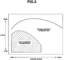
- auto-ignition range widened according to the present invention is indicated by shadowed area.
- auto-ignition is carried out at low to middle engine speeds with low to middle load, while spark-ignition is carried out at high engine speeds or full load.
- the shadowed area indicates an A/F range where stable controlled auto-ignition is recommended or allowed.
- Increasing A/F causes combustion stability to become worse and cyclic dispersion of engine torque to become great.
- Such lower limit is determined after consideration of an allowable deviation from the designed values targeted by an engine and design target of a vehicle powered by the engine.
- a stability threshold Sth represents such lower limit, A/F reaches a lean limit AFL when combustion stability reaches stability threshold Sth.
- the horizontal axis represents A/F because gas content of combustion chamber is air only. If the combustion chamber has burnt or EGR gas content as well as air content, the horizontal axis represents a ratio G/F, where G is the total of burnt or EGR gas content and air content. There is a G/F range, which allows auto-ignition in the same manner as the A/F range does.
- A/F or G/F ranges where auto-ignition is allowed are not wide enough. This derives from the fact that a variation of A/F or G/F causes a variation of beginning of burning (BOB) as shown in Figure 6.
- BOB of auto-ignition depends on speed of pre-reaction of gasoline fuel, that is, low temperature oxidation reaction. This reaction speed is mainly governed by A/F. If A/F is reduced to obtain a rich mixture, the reaction speed increases. As a result, burning begins at an early crank position before TDC of compression stroke, causing such rapid burning as to induce knock. If A/F is increased to obtain a lean mixture, the reaction speed drops. As a result, burning begins at a late crank position after TDC of compression stroke. The subsequent descending movement of piston makes it difficult to complete the burning, causing combustion instability.
- BOB is controlled to widen auto-ignition range.
- FIG. 7 is a graphical representation of variation of ignition delay against variation of cylinder temperature with A/F as a parameter.
- Ignition delay is a delay between injection of fuel and beginning of burning of the injected fuel.
- the ignition delay becomes short as cylinder temperature becomes high.
- ignition delay becomes short as A/F becomes rich.
- high temperature reaction occurs within this region.
- High temperature reaction of gasoline takes place at around 1000 K.
- an injection of gasoline fuel for dispersion within a gas having a temperature of 1000 K causes burning of the fuel to begin immediately after the injection.
- the present invention employs a technique to produce stratification, within a combustion chamber, of first gas content with second gas content.
- Both the first and second gases are oxygen-containing gases.
- the first gas is higher in temperature than the second gas.
- the first gas is burnt (or exhaust) gas from the previous cycle, and the second gas is fresh air.
- the stratification proves to be effective to minimize a drop in temperature of the first gas due to interaction with the second gas during induction and compression strokes.
- the inlet and outlet control devices 36 and 38 are so adjusted as to retain exhaust gas from the previous cycle to provide valve timing as illustrated in Figure 4.
- the inlet and outlet control devices 36 and 38 so adjusted as to retain exhaust gas serve as a first device for supplying, as the first gas, the retained exhaust gas to combustion chamber 20.
- Varying closing timing of the outlet control device 38 may vary the quantity of exhaust gas retained during exhaust gas retaining duration.
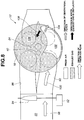
- Figure 8 provides a diagram illustrating how to supply fresh air to the combustion chamber within cylinder 16 during intake stroke.
- fresh air is supplied to the combustion chamber within the cylinder 16 through an intake port 90 only when a valve actuator 92 activates a port valve 94 to close another intake port 96.
- Both of the intake ports 90 and 96 are coupled to cylinder 16 and opens to the combustion chamber when the associated intake valves, not shown in Figure 8, open. There is no flow of air through intake port 96 when port valve 94 closes. Under this condition, the fresh air from intake manifold 22 is drawn through intake port 90 into the combustion chamber within cylinder 16 as indicated by arrows 98 and 100.
- Intake port 90 is coupled to cylinder 16 to provide an arrangement whereby the fresh air 98 and 100 drawn through intake port 90 into the combustion chamber generates a swirl about the cylinder axis.
- Centrifugal force causes air content 102 to rotate along the wall of cylinder 16, displacing exhaust gas content 106 inwardly (see arrow 108), thereby producing stratification of exhaust gas content 106 with fresh air content 102.
- Centrifugal force is applied to both exhaust gas content 106 and fresh air content 102.
- Fresh air content 102 is low temperature high-density gas as compared to exhaust gas content 106, which is high temperature low-density gas. The magnitude of centrifugal force imparted to fresh air content 102 is thus greater than the magnitude of centrifugal force imparted to exhaust gas content 106.
- intake port 90 serves as a second device for supplying fresh air, as the second gas, to combustion chamber 20 (see Figure 1) for producing stratification of exhaust gas content 106 with fresh air content 102.
- Figure 9 provides a diagram illustrating stratification between exhaust gas content 106 and fresh air content 102 at a crank position during compression stroke.
- exhaust gas content 102 is located near the cylinder axis and occupies a volume.
- the volume of exhaust gas content 106 decreases as piston 18 ascends from the illustrated position toward top dead center of compression stroke.
- intake port 90 may be replaced by a helical port.
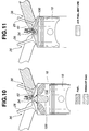
- system or method according to the present invention carries out a first injection of gasoline fuel into combustion chamber 20 for dispersion within fresh air content 102, and carries out a second injection of gasoline fuel into combustion chamber 20 for dispersion within exhaust gas content 106.
- the fuel injection system 78 (see Figure 2) activates fuel injector 34 for the first injection as shown in Figure 10, and reactivates the fuel injector 34 for second injection as shown in Figure 11.
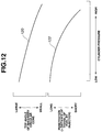
- Figure 12 illustrates performance curves 120 and 122 of fuel injector 34.
- Fuel injector 34 sprays gasoline fuel along an imaginary circular cone.
- the imaginary circular cone has a top angle.
- Curve 120 indicates how the top angle varies with variation of cylinder pressure. As cylinder pressure increases, distance of travel of fuel sprayed by fuel injector 34 for injection decreases. This distance is called “penetration”.
- Curve 122 indicates how the penetration varies with variation of cylinder pressure. Curves 120 and 122 clearly indicate that the top angle becomes small and penetration becomes short as cylinder pressure increases.
- the first injection begins at a crank position during intake stroke or the initial part of the subsequent compression stroke. Since cylinder pressure is still low, the top angle remains large and the penetration remains long. Thus, fuel droplets sprayed for the first injection reach fresh air content 102 for dispersion therein to form an air/fuel mixture.
- the second injection begins at around top dead center (TDC) of compression stroke. Since cylinder pressure is very high at around the TDC of compression stroke, the top angle becomes very small and the penetration becomes very short. Thus, fuel droplets sprayed for the second injection are dispersed within exhaust gas content 106.
- TDC top dead center
- the same fuel injector 34 is used for the first and second injections.
- Different fuel injectors may be used to carry out the first and second injections for dispersion of gasoline fuel within fresh air content 102 and for dispersion of gasoline fuel within exhaust gas content, respectively.
- Temperature of exhaust gas content 106 has been elevated to a level (as high as 1000 K) high enough for high temperature oxidation reaction of gasoline fuel at crank positions around top dead center of compression stroke.
- the second injection of gasoline fuel for dispersion within the exhaust gas content 106 causes the gasoline fuel to begin burning without any ignition delay, as mentioned before in connection with Figure 7.
- This auto-ignition of gasoline fuel within exhaust gas content 106 generates heat and energy high enough to cause auto-ignition of gasoline fuel dispersed within fresh air content 102.
- Fuel quantity for the second injection determines amount of energy generated by auto-ignition of the fuel within exhaust gas content 106.
- fuel quantity for the second injection should not exceed 10 percent of total fuel quantity for one cycle of combustion. This upper limit as high as 10 percent is preferable for reduction of NOx below a satisfactorily low level.
- the engine controller 14 can restrain fuel quantity for the second injection from exceeding 10 percent of total fuel quantity for one combustion cycle.
- the illustrated pressure curve 124 clearly indicates that auto-ignition of fuel within exhaust gas content 106 causes auto-ignition of fuel within fresh air content 102.
- controlling beginning of second injection can control beginning of high temperature oxidation reaction within exhaust gas content 106, which in turn controls beginning of burning of fuel within fresh air content 102.
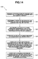
- a preferred embodiment of a method of the present invention for widening auto-ignition range is generally indicated at 130.
- stratification of exhaust gas content 106 of combustion chamber 20 with air content 102 thereof is produced.
- an EGR rate i. e., a ratio of the exhaust gas content 106 to total of the exhaust gas content 106 and the air content 102 is determined.
- Various values of the EGR rate may be found in a look-up table against engine speed and load.
- a value of cylinder pressure appropriate for the fuel injector 34 to spray gasoline fuel for dispersion within the air content 102 is determined.
- Various values of cylinder pressure may be found in a look-up table against the EGR rate.
- the performance curves 120 and 122 shown in Figure 12 are taken into account so that fuel droplets sprayed by the fuel injector 34 may displace within the air content 102 only.
- values of cylinder pressure at crank positions after each intake valve 36 closes are estimated. With the same crank position, cylinder pressure may take different values for different values of intake air pressure. Thus, intake air pressure is used in making the estimation by calculation or a table look-up operation.
- a first injection of gasoline fuel by the fuel injector 34 for dispersion within the air content 102 is carried out at a crank position having an estimated value of cylinder pressure matching the determined value of cylinder pressure.
- a second injection of gasoline fuel by the fuel injector 34 for dispersion within the exhaust gas content 106 is carried out at around top dead center of compression stroke.
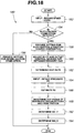
- the flow diagram illustrates a control routine, as generally indicated at 150, of the one preferred implementation of the present invention.
- the engine controller 14 inputs engine speed (RPM) and load (APO).
- RPM engine speed
- APO load
- interrogation block 154 the controller 14 refers to a map as illustrated in Figure 5 against engine speed and load to determine whether or not auto-ignition combustion is required. If this is not the case, spark-ignition combustion mode is required so that control goes to block 156.
- the controller 14 provides setting for spark-ignition combustion.
- control goes from block 154 to block 158.
- the controller 14 provides setting for auto-ignition combustion.
- the controller 14 adjusts inlet and outlet control devices 36 and 38 for retaining exhaust gas in a manner as illustrated in Figure 4.
- the controller 14 determines an EGR rate, i.e., a ratio of exhaust gas content 106 to the total of the exhaust gas content and fresh air content 102 (see Figures 10 and 11).
- the EGR rate may be determined as a function of a crank angle at which the outlet control device 38 closes.
- the crank angle at which the outlet control device 38 closes determines a volume of exhaust gas from the previous cycle retained for supply for the subsequent combustion cycle.
- the controller 14 inputs intake air pressure P0.
- the controller 14 may alter the polytropic index n in response to air/fuel ratio and/or load. If desired, the calculation of the equation may be avoided. In this case, values of cylinder pressure at crank positions are determined by simulation or experiments and stored in a non-volatile memory against crank positions, respectively. The controller 14 may refers to this data to determine values of cylinder pressure at crank positions.
- At least one of operating conditions including load and engine speed determines beginning of injection for second injection BOI_S.
- Figure 16 provides a knock intensity variation curve 180
- Figure 17 provides an ignition delay variation curve 182.
- Curve 180 of Figure 16 clearly indicates that if beginning of burning of gasoline fuel dispersed within fresh air content 102 advances, knock intensity becomes strong. This is because temperature and pressure become high at around top dead center of compression stroke, causing rapid burning to take place. Auto-ignition range may extend toward high load by retarding beginning of burning of gasoline fuel within fresh air content 102 as load request becomes high. In the second embodiment, engine controller 14 retards beginning of second injection as load request becomes high.
- Curve 182 of Figure 17 clearly indicates that an ignition delay becomes large as engine speed becomes high.
- the ignition delay represents a delay in terms of crank angle between beginning of second injection and beginning of burning of gasoline fuel within fresh air content 102.
- engine controller 14 advances beginning of second injection as engine speed becomes high.
- the beginning of second injection is subject to variation in response to load request and/or engine speed within the neighborhood of top dead center of compression stroke.
- cylinder pressure at which second injection begins is still at a level high enough for fuel injector 34 to spray gasoline fuel for dispersion within exhaust gas content 106.
- FIG. 18 illustrates a flow of operations for carrying out control of the system of Figure 1 according to the second embodiment of the present invention.
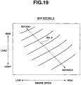
- Figure 19 is a map containing optimum crank positions for beginning of injection for second injection against load and engine speed. This map is used in determining beginning of injection for second injection BOI_S in the flow diagram Figure 18.
- the flow diagram 190 of Figure 18 is substantially the same as flow diagram 150 of Figure 15.
- like reference numerals designate like or corresponding blocks in Figures 15 and 18.
- flow diagram 190 is different from flow diagram 150 in that although beginning of injection for first injection BOI_F is determined in block 192 in substantially the same manner as it was determined in block 170 of Figure 15, beginning of injection for second injection BOI_S is determined in block 194 by performing a table look-up operation of the map shown in Figure 19 against load and engine speed. As will be readily understood from the map of Figure 19, BOI_S retards as load becomes high and it advances as engine speed becomes high.
- temperature of exhaust gas within an exhaust port is detected by exhaust gas temperature sensor 44, and EGR rate, i.e., a ratio of quantity of exhaust gas content 106 to total quantity of the exhaust gas content 106 and fresh air content 102 is increased as the temperature of exhaust gas drops.
- Figure 20A illustrates quantity of exhaust gas content 106 at around top dead center of compression stroke when exhaust gas from the previous cycle has a normal level of temperature
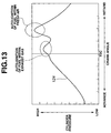
- Figure 20B provides a temperature distribution within the combustion chamber of Figure 20A. If temperature of exhaust gas Texh from the previous cycle is high enough and at the normal level, temperature of exhaust gas content 106 becomes high enough to allow high temperature oxidation reaction of gasoline fuel at around top dead of compression stroke irrespective of variation of EGR rate.
- Figure 21A illustrates quantity of exhaust gas content 106 at around top dead center of compression stroke when exhaust gas from the previous cycle has temperature considerably lower than the normal level of temperature
- Figure 21B is a temperature distribution within the combustion chamber of Figure 21A.
- temperature of exhaust gas content 106 cannot become high enough to allow high temperature oxidation reaction of gasoline fuel at around top dead of compression stroke.
- it is difficult to sustain high temperature oxidation reaction of gasoline fuel.
- high temperature oxidation reaction of gasoline fuel is sustained by increasing EGR rate, i.e., a ratio of quantity of exhaust gas content 106 to total quantity of exhaust gas content 106 and fresh air content 102 when exhaust gas temperature Texh drops.
- Figure 22A illustrates increased quantity of exhaust gas content 106 at around top dead center of compression stroke when exhaust gas from the previous cycle has temperature considerably lower than a normal level of temperature
- Figure 22B is a temperature distribution within combustion chamber of Figure 22A. The temperature distribution clearly indicates that the temperature of exhaust gas content 106 has elevated sufficiently high owing to an increased conservation of heat within exhaust gas content 106.
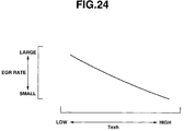
- Figure 24 is a map, stored in a non-volatile memory, containing optimum values of EGR rate against varying values of exhaust gas temperature Texh.
- a desired value in EGR rate is found in the map of Figure 24 against exhaust gas temperature Texh, and inlet and outlet control devices 36 and 38 are adjusted in response to EGR rate to vary exhaust gas retaining duration (minus overlap in Figure 4).
- Flow diagram 200 of Figure 23 is substantially the same as flow diagram 150 of Figure 15.
- like reference numerals designate like or corresponding blocks in Figures 15 and 23.
- flow diagram 200 is different from flow diagram 150 in that blocks 202, 204, and 206 have replaced blocks 160 and 162 of Figure 15.
- controller 14 input exhaust gas temperature Texh in block 202.
- controller 14 determines EGR rate by performing a table look-up operation of map shown in Figure 24 using Texh.
- controller 14 adjusts inlet and outlet control devices 36 and 38 for retaining exhaust gas in response to EGR rate determined in block 204. Specifically, the exhaust gas retaining duration is varied against variation of EGR rate determined in block 204.
- the EGR rate which has been determined in block 204, is used in determining BOI_F and BOI_S in block 170 in the same manner as EGR rate determined in block 162 was used in determining BOI_F and BOI_S in block 170 in Figure 15.
- exhaust gas temperature is detected and used for processing. If desired, exhaust gas temperature may be estimated and the estimated value of exhaust gas temperature may be used for processing.
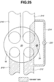
- EGR pipe 214 has an inlet end coupled to exhaust port 212 and an outlet end coupled to an intake port 216.
- Intake port 216 is coupled to cylinder 16 for supplying the exhaust gas to combustion chamber 20.
- Another intake port 218 is coupled to cylinder 16 for supplying fresh air to combustion chamber 20 thereby to place the exhaust gas content locally within combustion chamber 20.
- An EGR valve 220 is provided to regulate flow through EGR pipe 214.
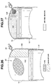
- a fuel injector 34 is located for direct injection of gasoline fuel for dispersion within fresh air content 102 during a first injection as shown in Figure 26 and for direct injection of gasoline fuel for dispersion within exhaust gas content 106 during a second injection as shown in Figure 27.
- Figure 28 provides a flow diagram, as generally indicated at 240, illustrating a flow of operations for carrying out control of the system of Figure 1 as modified as illustrated in Figure 25 according to the fourth preferred embodiment of the present invention.
- Flow diagram 240 of Figure 28 is substantially the same as flow diagram 190 of Figure 18.
- like reference numerals designate like or corresponding blocks in Figures 18 and 28.
- flow diagram 240 is different from flow diagram 190 in that block 242 has replaced block 160 of Figure 18.
- controller 14 adjusts or controls EGR valve 220 to provide an appropriate quantify of exhaust gas supply to intake port 216 during intake stroke of piston 18.
- stratification is produced by adjusting inlet and outlet control devices 36 and 38 so as to open intake and exhaust ports during at least a part of intake stroke as readily seen from Figures 29A and 31 to draw exhaust gas from at least one of exhaust ports into combustion chamber 20.
- a fuel injector is located near exhaust port side for first and second injections.
- Figure 30 is a valve lift diagram for spark-ignition combustion mode and Figure 31 is a valve lift diagram for auto-ignition combustion mode.
- the valve lift diagram of Figure 31 clearly show that both intake and exhaust valves 26 and 28 open during intake stroke to allow supply of exhaust gas to combustion chamber 20.
- Figure 32 is a diagram illustrating first injection of gasoline fuel into combustion chamber 20 for dispersion within fresh air content 102 of the combustion chamber.
- Figure 33 is a diagram illustrating second injection of gasoline fuel into combustion chamber 20 for dispersion within exhaust gas content 106.
Landscapes
- Engineering & Computer Science (AREA)
- Chemical & Material Sciences (AREA)
- Combustion & Propulsion (AREA)
- Mechanical Engineering (AREA)
- General Engineering & Computer Science (AREA)
- Electrical Control Of Air Or Fuel Supplied To Internal-Combustion Engine (AREA)
- Combustion Methods Of Internal-Combustion Engines (AREA)
- Combined Controls Of Internal Combustion Engines (AREA)
- Exhaust-Gas Circulating Devices (AREA)
- Output Control And Ontrol Of Special Type Engine (AREA)
Abstract
Description
Claims (17)
- A lean burn internal combustion engine having at least one cylinder with a piston reciprocating therein to define a combustion chamber, comprising:a first device for supplying first oxygen containing gas to the combustion chamber;a second device for supplying second oxygen containing gas to the combustion chamber for producing stratification, within the combustion chamber, of first gas content with second gas content, the first gas being higher in temperature than the second gas; anda fuel injection system for carrying out a first injection of gasoline fuel into the combustion chamber for dispersion within the second gas content, and for carrying out a second injection of gasoline fuel into the combustion chamber for dispersion within the first gas content, thereby to accomplish auto-ignition of gasoline fuel within the first gas content of the combustion chamber.
- The engine as claimed in claim 1, wherein the first gas is exhaust gas from the previous cycle, and the second gas is air.
- The engine as claimed in claim 2, further comprising a controller for adjusting beginning of the second injection at around top dead center position of compression stroke of the piston.
- The engine as claimed in claim 3, wherein the controller determines beginning of the second injection in response to at least one of operating conditions of the engine.
- The engine as claimed in claim 3, wherein the controller determines load request, and retards beginning of the second injection as the determined load request becomes high.
- The engine as claimed in claim 3, wherein the controller determines engine speed of the engine, and advances beginning of the second injection as the engine speed becomes high.
- The engine as claimed in claim 3, wherein the controller restrains fuel quantity for the second injection from exceeding 10 percent of total fuel quantity for one cycle of combustion.
- The engine as claimed in claim 3, wherein the fuel injection system includes a fuel injector for direct injection of gasoline fuel into the combustion chamber, and wherein the controller activates the fuel injector for the first injection and reactivates the fuel injector for the second injection.
- The engine as claimed in claim 3, wherein the first device includes:an inlet control device for controlling flow into the combustion chamber; andan outlet control device for controlling flow out of the combustion chamber, the inlet and outlet control devices being so adjusted as to retain exhaust gas from the previous cycle, as the first gas, during exhaust stroke of the piston; and wherein the second device includes:an intake port coupled to the cylinder to provide an intake arrangement whereby the second gas drawn through the intake port into the combustion chamber generates swirl about a cylinder axis within the combustion chamber to displace the first gas content inwardly toward the cylinder axis for producing stratification of the first gas content with the second gas content.
- The engine as claimed in claim 3, wherein the first device includes:an intake port coupled to the cylinder for supplying, as the first gas, exhaust gas to the combustion chamber, which exhaust gas is fed thereto after passing through an external EGR pipe; and wherein the second device includes:an intake port coupled to the cylinder for supplying the second gas to the combustion chamber thereby to place the first gas content locally within the combustion chamber.
- The engine as claimed in claim 3, wherein the first device includes:an inlet control device for controlling flow into the combustion chamber through an intake port;an outlet control device for controlling flow out of the combustion chamber through an exhaust port, the inlet and outlet control devices being so adjusted as to open the intake and exhaust ports during an sintake stroke of the piston to draw exhaust gas, as the first gas, into the combustion chamber.
- The engine as claimed in claim 3, wherein the controller increases a ratio of quantity of the first gas content of the combustion chamber to total quantity of the first and second gas contents of the combustion chamber as temperature of exhaust gas drops.
- A method of widening auto-ignition range of a lean burn internal combustion engine having at least one cylinder with a piston reciprocating therein to define a combustion chamber, comprising:producing stratification of exhaust gas content of the combustion chamber with air content thereof;carrying out a first injection of gasoline fuel for dispersion within the air content; andcarrying out a second injection of gasoline fuel for dispersion within the exhaust gas content.
- The method as claimed in claim 13, wherein load request on the engine determines beginning of the second injection.
- The method as claimed in claim 13, wherein engine speed of the engine determines beginning of the second injection.
- A computer readable storage medium having stored therein data representing instructions executable by a controller to widen auto-ignition range of a lean burn internal combustion engine, the engine having at least one cylinder, and a fuel injector for direct injection of gasoline fuel into the combustion chamber, the computer readable storage medium comprising:instructions for producing stratification of exhaust gas content of the combustion chamber with air content of the combustion chamber;instructions for determining a ratio of the exhaust gas content to total of the exhaust gas content and the air content;instructions for determining a value of cylinder pressure appropriate for the fuel injector to spray gasoline fuel for dispersion within the air content;instructions for estimating values of cylinder pressure at crank positions, respectively;instructions for carrying out a first injection of gasoline fuel by the fuel injector at a crank position having an estimated value of cylinder pressure matching the determined value of cylinder pressure; andinstructions for carrying out a second injection of gasoline fuel by the fuel injector for dispersion within the exhaust gas content at around top dead center of compression stroke of the piston.
- A system for widening auto-ignition range of a lean burn internal combustion engine having at least one cylinder with a piston reciprocating therein to define a combustion chamber, comprising:means for supplying exhaust gas to the combustion chamber;means for supplying air to the combustion chamber for producing stratification, within the combustion chamber, of exhaust gas content with air content; andmeans for carrying out a first injection of gasoline fuel into the combustion chamber for dispersion within the air content, and for carrying out a second injection of gasoline fuel into the combustion chamber for dispersion within the exhaust gas content, thereby to accomplish auto-ignition of gasoline fuel within the exhaust gas content of the combustion chamber.
Applications Claiming Priority (2)
| Application Number | Priority Date | Filing Date | Title |
|---|---|---|---|
| JP2000143860 | 2000-05-16 | ||
| JP2000143860A JP2001323828A (en) | 2000-05-16 | 2000-05-16 | Compression self-ignition gasoline engine |
Publications (3)
| Publication Number | Publication Date |
|---|---|
| EP1156199A2 true EP1156199A2 (en) | 2001-11-21 |
| EP1156199A3 EP1156199A3 (en) | 2003-03-19 |
| EP1156199B1 EP1156199B1 (en) | 2004-10-13 |
Family
ID=18650615
Family Applications (1)
| Application Number | Title | Priority Date | Filing Date |
|---|---|---|---|
| EP01111563A Expired - Lifetime EP1156199B1 (en) | 2000-05-16 | 2001-05-11 | Controlled auto-ignition lean burn stratified engine by intelligent injection |
Country Status (4)
| Country | Link |
|---|---|
| US (1) | US6497213B2 (en) |
| EP (1) | EP1156199B1 (en) |
| JP (1) | JP2001323828A (en) |
| DE (1) | DE60106325T2 (en) |
Cited By (6)
| Publication number | Priority date | Publication date | Assignee | Title |
|---|---|---|---|---|
| WO2003002857A1 (en) * | 2001-06-28 | 2003-01-09 | Ford Global Technologies, Inc. | Engine with controlled auto-ignition |
| EP1435442A1 (en) * | 2002-12-30 | 2004-07-07 | Ford Global Technologies, Inc. | Internal combustion engine, method for auto-ignition operation and computer readable storage device |
| WO2008066202A1 (en) * | 2006-11-30 | 2008-06-05 | Kabushiki Kaisha Toyota Jidoshokki | Homogeneous charge compression ignition engine |
| US7400966B2 (en) | 2002-12-30 | 2008-07-15 | Ford Global Technologies, Llc | Method for auto-ignition operation and computer readable storage device for use with an internal combustion engine |
| EP1643104A3 (en) * | 2004-09-30 | 2009-04-08 | Mahle Powertrain Limited | Engine |
| US7681550B2 (en) | 2005-02-24 | 2010-03-23 | Toyota Jidosha Kabushiki Kaisha | Internal combustion engine |
Families Citing this family (44)
| Publication number | Priority date | Publication date | Assignee | Title |
|---|---|---|---|---|
| WO2001055567A1 (en) * | 2000-01-25 | 2001-08-02 | Kabushiki Kaisha Toyota Chuo Kenkyusho | Direct injection type internal combustion engine |
| JP3945152B2 (en) * | 2000-11-21 | 2007-07-18 | 日産自動車株式会社 | Combustion control device for internal combustion engine |
| JP3988383B2 (en) * | 2000-12-19 | 2007-10-10 | 日産自動車株式会社 | Self-igniting engine and its control device |
| JP3800020B2 (en) * | 2001-03-13 | 2006-07-19 | 日産自動車株式会社 | Compression self-ignition engine |
| GB2374633C (en) * | 2001-04-19 | 2015-03-25 | Lotus Car | A four stroke engine |
| EP1389679B1 (en) * | 2001-05-22 | 2017-11-29 | Hitachi, Ltd. | Compression ignition internal combustion engine |
| JP3885524B2 (en) | 2001-06-25 | 2007-02-21 | 日産自動車株式会社 | Compression self-ignition internal combustion engine |
| ITTO20010660A1 (en) * | 2001-07-06 | 2003-01-06 | Fiat Ricerche | MULTI-CYLINDER DIESEL ENGINE WITH VARIABLE VALVE OPERATION. |
| JP3937791B2 (en) | 2001-10-15 | 2007-06-27 | 日産自動車株式会社 | Control device for multi-cylinder diesel engine |
| US6964256B2 (en) * | 2002-03-28 | 2005-11-15 | Mazda Motor Corporation | Combustion control apparatus for an engine |
| WO2004059149A1 (en) * | 2002-12-23 | 2004-07-15 | Jacobs Vehicle Systems, Inc. | Method of modifying exhaust valve timing to improve engine performance |
| JP4472932B2 (en) * | 2003-02-07 | 2010-06-02 | いすゞ自動車株式会社 | Engine combustion control device |
| JP4005941B2 (en) * | 2003-06-03 | 2007-11-14 | 株式会社日立製作所 | Combustion control device and combustion control method for in-cylinder injection engine |
| US7021276B2 (en) * | 2004-03-25 | 2006-04-04 | International Engine Intellectual Property Company, Llc | Control strategy for HCCI-CD combustion in a diesel engine using two fuel injection phases |
| US7487029B2 (en) * | 2004-05-21 | 2009-02-03 | Pratt & Whitney Canada | Method of monitoring gas turbine engine operation |
| US7128062B2 (en) * | 2004-07-12 | 2006-10-31 | General Motors Corporation | Method for mid load operation of auto-ignition combustion |
| US6994072B2 (en) * | 2004-07-12 | 2006-02-07 | General Motors Corporation | Method for mid load operation of auto-ignition combustion |
| US7080613B2 (en) * | 2004-07-12 | 2006-07-25 | General Motors Corporation | Method for auto-ignition combustion control |
| DE102004034505B4 (en) * | 2004-07-16 | 2018-01-04 | Daimler Ag | Method for operating an internal combustion engine |
| CN101218423B (en) * | 2005-03-03 | 2011-12-21 | 通用汽车环球科技运作公司 | Method of switching between controlled auto-ignition and spark ignition modes for direct fuel injection engines |
| WO2006096423A2 (en) * | 2005-03-03 | 2006-09-14 | General Motors Global Technology Operations, Inc. | Speed transient control methods for direct-injection engines with controlled auto-ignition combustion |
| US7370633B2 (en) * | 2005-03-03 | 2008-05-13 | Gm Global Technology Operations, Inc. | Load transient control methods for direct-injection engines with controlled auto-ignition combustion |
| WO2006096424A2 (en) * | 2005-03-03 | 2006-09-14 | General Motors Global Technology Operations, Inc. | Method for load transient control between lean and stoichiometric combustion modes of direct-injection engines with controlled auto-ignition combustion |
| US7128046B1 (en) * | 2005-03-29 | 2006-10-31 | Sandia National Laboratories | Fuel mixture stratification as a method for improving homogeneous charge compression ignition engine operation |
| SE529412C2 (en) * | 2005-12-21 | 2007-08-07 | Scania Cv Ab | Arrangement and procedure of an internal combustion engine |
| JP4946173B2 (en) * | 2006-05-17 | 2012-06-06 | 日産自動車株式会社 | Internal combustion engine |
| US8887691B2 (en) * | 2007-04-17 | 2014-11-18 | GM Global Technology Operations LLC | Method and apparatus for selecting a combustion mode for an internal combustion engine |
| JP5183630B2 (en) * | 2007-05-21 | 2013-04-17 | 株式会社畑村エンジン研究事務所 | 4-cycle engine |
| JP5020909B2 (en) * | 2008-09-02 | 2012-09-05 | 本田技研工業株式会社 | Variable valve operating device for internal combustion engine |
| JP5457095B2 (en) * | 2009-07-16 | 2014-04-02 | 国立大学法人 千葉大学 | Premixed compression ignition gasoline engine |
| JP4877857B2 (en) * | 2009-12-01 | 2012-02-15 | 本田技研工業株式会社 | Control device for internal combustion engine |
| US8776762B2 (en) * | 2009-12-09 | 2014-07-15 | GM Global Technology Operations LLC | HCCI mode switching control system and method |
| US8627804B2 (en) * | 2010-11-16 | 2014-01-14 | GM Global Technology Operations LLC | Transient control strategy in spark-assisted HCCI combustion mode |
| US8689767B1 (en) * | 2011-01-26 | 2014-04-08 | Sandia Corporation | Method for operating homogeneous charge compression ignition engines using conventional gasoline |
| US9151240B2 (en) | 2011-04-11 | 2015-10-06 | GM Global Technology Operations LLC | Control system and method for a homogeneous charge compression ignition (HCCI) engine |
| JP5626120B2 (en) * | 2011-05-25 | 2014-11-19 | マツダ株式会社 | Engine control device |
| JP5781855B2 (en) * | 2011-07-21 | 2015-09-24 | 株式会社日本自動車部品総合研究所 | Spray characteristic estimation device |
| KR101393571B1 (en) | 2012-12-17 | 2014-05-12 | 기아자동차 주식회사 | Engine having variable valve timint device and variable tumble device |
| JP5949669B2 (en) * | 2013-06-04 | 2016-07-13 | トヨタ自動車株式会社 | Heat generation rate waveform creation device and combustion state diagnostic device for internal combustion engine |
| JP2015057544A (en) * | 2013-09-16 | 2015-03-26 | ダイヤモンド電機株式会社 | Combustion controller for gasoline engine |
| JP6315005B2 (en) * | 2016-02-15 | 2018-04-25 | トヨタ自動車株式会社 | Control device for internal combustion engine |
| KR20200052492A (en) * | 2018-11-06 | 2020-05-15 | 현대자동차주식회사 | Fuel injection control system and method |
| US11834983B2 (en) | 2019-07-15 | 2023-12-05 | The Research Foundation For The State University Of New York | Method for control of advanced combustion through split direct injection of high heat of vaporization fuel or water fuel mixtures |
| JP7468307B2 (en) * | 2020-11-13 | 2024-04-16 | マツダ株式会社 | Engine System |
Family Cites Families (16)
| Publication number | Priority date | Publication date | Assignee | Title |
|---|---|---|---|---|
| JPS51108104A (en) * | 1975-03-19 | 1976-09-25 | Toyoda Chuo Kenkyusho Kk | |
| US4414940A (en) * | 1981-04-13 | 1983-11-15 | Loyd Robert W | Conditioned compression ignition system for stratified charge engines |
| JP3518688B2 (en) * | 1992-07-02 | 2004-04-12 | コベントリー ユニバーシティー | Internal combustion engine |
| JP3558370B2 (en) | 1994-06-07 | 2004-08-25 | 株式会社豊田中央研究所 | Compression ignition gasoline engine |
| GB2313623A (en) * | 1996-06-01 | 1997-12-03 | Ford Motor Co | Fuel supply to EGR gases in a lean-burn auto-ignition i.c. engine |
| JPH10266878A (en) | 1997-03-26 | 1998-10-06 | Toyota Motor Corp | Control device for 4-stroke engine |
| DE19727385C2 (en) * | 1997-06-27 | 2002-10-10 | Bosch Gmbh Robert | System for operating an internal combustion engine with direct injection, in particular a motor vehicle |
| US6227151B1 (en) * | 1997-08-01 | 2001-05-08 | Ford Global Technologies, Inc. | Gasoline internal combustion engine |
| GB2327980A (en) * | 1997-08-01 | 1999-02-10 | Ford Global Tech Inc | Gasoline i.c. engine with spark-ignition and auto-ignition in the same cylinder |
| FR2768180B1 (en) * | 1997-09-09 | 1999-10-08 | Inst Francais Du Petrole | OPERATING PROCESS OF A 4-STROKE ENGINE, IN CONTROLLED SELF-IGNITION |
| US5918577A (en) * | 1998-02-04 | 1999-07-06 | Ford Global Technologies, Inc. | Stratified exhaust residual engine |
| JP3880197B2 (en) | 1998-04-10 | 2007-02-14 | 株式会社日立製作所 | Valve operating device for internal combustion engine |
| EP1108868B1 (en) * | 1999-12-14 | 2005-04-13 | Nissan Motor Co., Ltd. | Compression self-ignition gasoline engine |
| JP3815163B2 (en) * | 2000-01-25 | 2006-08-30 | 日産自動車株式会社 | Compression self-ignition internal combustion engine |
| US6401688B2 (en) * | 2000-01-27 | 2002-06-11 | Nissan Motor Co., Ltd. | Auto-ignition combustion management in internal combustion engine |
| US6321715B1 (en) * | 2000-06-23 | 2001-11-27 | Visteon Global Technologies, Inc. | Conjugate vortex stratified exhaust gas recirculation system for internal combustion engine |
-
2000
- 2000-05-16 JP JP2000143860A patent/JP2001323828A/en active Pending
-
2001
- 2001-05-11 DE DE60106325T patent/DE60106325T2/en not_active Expired - Fee Related
- 2001-05-11 EP EP01111563A patent/EP1156199B1/en not_active Expired - Lifetime
- 2001-05-14 US US09/853,702 patent/US6497213B2/en not_active Expired - Fee Related
Cited By (8)
| Publication number | Priority date | Publication date | Assignee | Title |
|---|---|---|---|---|
| WO2003002857A1 (en) * | 2001-06-28 | 2003-01-09 | Ford Global Technologies, Inc. | Engine with controlled auto-ignition |
| EP1435442A1 (en) * | 2002-12-30 | 2004-07-07 | Ford Global Technologies, Inc. | Internal combustion engine, method for auto-ignition operation and computer readable storage device |
| US7400966B2 (en) | 2002-12-30 | 2008-07-15 | Ford Global Technologies, Llc | Method for auto-ignition operation and computer readable storage device for use with an internal combustion engine |
| US7441538B2 (en) | 2002-12-30 | 2008-10-28 | Ford Global Technologies, Llc | Method for auto-ignition operation and computer storage device for use with an internal combustion engine |
| EP1643104A3 (en) * | 2004-09-30 | 2009-04-08 | Mahle Powertrain Limited | Engine |
| US7681550B2 (en) | 2005-02-24 | 2010-03-23 | Toyota Jidosha Kabushiki Kaisha | Internal combustion engine |
| WO2008066202A1 (en) * | 2006-11-30 | 2008-06-05 | Kabushiki Kaisha Toyota Jidoshokki | Homogeneous charge compression ignition engine |
| CN101512119B (en) * | 2006-11-30 | 2011-04-27 | 株式会社丰田自动织机 | Homogeneous charge compression ignition engine |
Also Published As
| Publication number | Publication date |
|---|---|
| US20010045201A1 (en) | 2001-11-29 |
| US6497213B2 (en) | 2002-12-24 |
| EP1156199A3 (en) | 2003-03-19 |
| JP2001323828A (en) | 2001-11-22 |
| DE60106325T2 (en) | 2005-02-17 |
| DE60106325D1 (en) | 2004-11-18 |
| EP1156199B1 (en) | 2004-10-13 |
Similar Documents
| Publication | Publication Date | Title |
|---|---|---|
| EP1156199B1 (en) | Controlled auto-ignition lean burn stratified engine by intelligent injection | |
| US6386177B2 (en) | System and method for auto-ignition of gasoline internal combustion engine | |
| US6636797B2 (en) | Enhanced multiple injection for auto-ignition in internal combustion engines | |
| US6508229B2 (en) | Auto-ignition combustion management in internal combustion engine | |
| US7194996B2 (en) | Internal combustion engine and method for auto-ignition operation of said engine | |
| CN102084108B (en) | Method and apparatus for improving light load and idle HCCI combustion control | |
| US6994072B2 (en) | Method for mid load operation of auto-ignition combustion | |
| US6609493B2 (en) | System and method for enhanced combustion control in an internal combustion engine | |
| US7080613B2 (en) | Method for auto-ignition combustion control | |
| US20100077990A1 (en) | Control of spark ignited internal combustion engine | |
| CN101858270B (en) | Method and apparatus for controlling combustion mode transitions in an internal combustion engine | |
| US10704523B2 (en) | Control system of compression-ignition engine | |
| US10704524B2 (en) | Control system of compression-ignition engine | |
| US10920655B2 (en) | Control device for compression ignition engine | |
| CN101218423A (en) | Method for transitioning between controlled auto-ignition and spark-ignition modes in a direct fuel injection engine | |
| JPH11117777A (en) | Internal combustion engine control method | |
| US9528426B2 (en) | Method of estimating duration of auto-ignition phase in a spark-assisted compression ignition operation | |
| US7194999B2 (en) | Combustion control apparatus for direct-injection spark-ignition internal combustion engine | |
| JP3257430B2 (en) | Exhaust heating device | |
| US7712440B2 (en) | Increased HCCI operation window | |
| US11092108B2 (en) | Control device for compression self-ignition engine | |
| JPH07189767A (en) | Control apparatus and method for spark ignition internal combustion engine | |
| JP2006161733A (en) | In-cylinder direct injection spark ignition internal combustion engine controller |
Legal Events
| Date | Code | Title | Description |
|---|---|---|---|
| PUAI | Public reference made under article 153(3) epc to a published international application that has entered the european phase |
Free format text: ORIGINAL CODE: 0009012 |
|
| 17P | Request for examination filed |
Effective date: 20010511 |
|
| AK | Designated contracting states |
Kind code of ref document: A2 Designated state(s): AT BE CH CY DE DK ES FI FR GB GR IE IT LI LU MC NL PT SE TR |
|
| AX | Request for extension of the european patent |
Free format text: AL;LT;LV;MK;RO;SI |
|
| PUAL | Search report despatched |
Free format text: ORIGINAL CODE: 0009013 |
|
| AK | Designated contracting states |
Kind code of ref document: A3 Designated state(s): AT BE CH CY DE DK ES FI FR GB GR IE IT LI LU MC NL PT SE TR |
|
| AX | Request for extension of the european patent |
Extension state: AL LT LV MK RO SI |
|
| 17Q | First examination report despatched |
Effective date: 20031028 |
|
| AKX | Designation fees paid |
Designated state(s): DE FR GB |
|
| GRAP | Despatch of communication of intention to grant a patent |
Free format text: ORIGINAL CODE: EPIDOSNIGR1 |
|
| GRAS | Grant fee paid |
Free format text: ORIGINAL CODE: EPIDOSNIGR3 |
|
| GRAA | (expected) grant |
Free format text: ORIGINAL CODE: 0009210 |
|
| AK | Designated contracting states |
Kind code of ref document: B1 Designated state(s): DE FR GB |
|
| REG | Reference to a national code |
Ref country code: GB Ref legal event code: FG4D |
|
| REG | Reference to a national code |
Ref country code: IE Ref legal event code: FG4D |
|
| REF | Corresponds to: |
Ref document number: 60106325 Country of ref document: DE Date of ref document: 20041118 Kind code of ref document: P |
|
| ET | Fr: translation filed | ||
| PLBE | No opposition filed within time limit |
Free format text: ORIGINAL CODE: 0009261 |
|
| STAA | Information on the status of an ep patent application or granted ep patent |
Free format text: STATUS: NO OPPOSITION FILED WITHIN TIME LIMIT |
|
| 26N | No opposition filed |
Effective date: 20050714 |
|
| PGFP | Annual fee paid to national office [announced via postgrant information from national office to epo] |
Ref country code: DE Payment date: 20070503 Year of fee payment: 7 |
|
| PGFP | Annual fee paid to national office [announced via postgrant information from national office to epo] |
Ref country code: GB Payment date: 20070509 Year of fee payment: 7 |
|
| PGFP | Annual fee paid to national office [announced via postgrant information from national office to epo] |
Ref country code: FR Payment date: 20070510 Year of fee payment: 7 |
|
| GBPC | Gb: european patent ceased through non-payment of renewal fee |
Effective date: 20080511 |
|
| REG | Reference to a national code |
Ref country code: FR Ref legal event code: ST Effective date: 20090119 |
|
| PG25 | Lapsed in a contracting state [announced via postgrant information from national office to epo] |
Ref country code: DE Free format text: LAPSE BECAUSE OF NON-PAYMENT OF DUE FEES Effective date: 20081202 Ref country code: FR Free format text: LAPSE BECAUSE OF NON-PAYMENT OF DUE FEES Effective date: 20080602 |
|
| PG25 | Lapsed in a contracting state [announced via postgrant information from national office to epo] |
Ref country code: GB Free format text: LAPSE BECAUSE OF NON-PAYMENT OF DUE FEES Effective date: 20080511 |