EP1155930A2 - Cylindrical key lock for anti-theft device for vehicle steering wheel immobilisation - Google Patents
Cylindrical key lock for anti-theft device for vehicle steering wheel immobilisation Download PDFInfo
- Publication number
- EP1155930A2 EP1155930A2 EP01117192A EP01117192A EP1155930A2 EP 1155930 A2 EP1155930 A2 EP 1155930A2 EP 01117192 A EP01117192 A EP 01117192A EP 01117192 A EP01117192 A EP 01117192A EP 1155930 A2 EP1155930 A2 EP 1155930A2
- Authority
- EP
- European Patent Office
- Prior art keywords
- lock
- key
- cylindrical
- fixed part
- steering wheel
- Prior art date
- Legal status (The legal status is an assumption and is not a legal conclusion. Google has not performed a legal analysis and makes no representation as to the accuracy of the status listed.)
- Withdrawn
Links
Images


Classifications
-
- B—PERFORMING OPERATIONS; TRANSPORTING
- B60—VEHICLES IN GENERAL
- B60R—VEHICLES, VEHICLE FITTINGS, OR VEHICLE PARTS, NOT OTHERWISE PROVIDED FOR
- B60R25/00—Fittings or systems for preventing or indicating unauthorised use or theft of vehicles
- B60R25/01—Fittings or systems for preventing or indicating unauthorised use or theft of vehicles operating on vehicle systems or fittings, e.g. on doors, seats or windscreens
- B60R25/02—Fittings or systems for preventing or indicating unauthorised use or theft of vehicles operating on vehicle systems or fittings, e.g. on doors, seats or windscreens operating on the steering mechanism
- B60R25/022—Fittings or systems for preventing or indicating unauthorised use or theft of vehicles operating on vehicle systems or fittings, e.g. on doors, seats or windscreens operating on the steering mechanism operating on the steering wheel, e.g. bars locked to the steering wheel rim
- B60R25/0225—Fittings or systems for preventing or indicating unauthorised use or theft of vehicles operating on vehicle systems or fittings, e.g. on doors, seats or windscreens operating on the steering mechanism operating on the steering wheel, e.g. bars locked to the steering wheel rim using a rod locked on the steering wheel rim
Definitions
- the present invention relates to an anti-theft device for vehicles; in particular, it refers to a cylindrical key lock for an anti-theft device of the type that is secured to the steering wheel of a vehicle and that prevents the rotation of the steering wheel.
- cylindrical key locks in particular for vehicles; generally they consist of a cylindrical body provided with grooves and/or protrusions suitable for coupling with corresponding complementary protrusions and grooves provided in another cylindrical body, hollowed, in which said first cylindrical body is inserted; both are provided with positioning elements which, when positioned in a predetermined position, allow the movable cylindrical body to rotate relatively to the fixed cylindrical body, and therefore the operation of the lock.
- an anti-theft device 2 realised according to a first embodiment of the present invention and able to be coupled with a steering wheel of a vehicle, is constituted by an elongated body provided with means for securing said steering wheel to the rim 10, said elongated body comprising a primary part 4 provided with first 12 and second 14 means able to engage with respective diametrically opposite parts of the rim 10 of said steering wheel, and a secondary part 6 able to make said primary part 4 longer in order to prevent the rotation of said steering wheel.
- Said primary part 4 and said secondary part 6 are hinged between them by means of a hinge pin 8, so that said secondary part 6 can rotate with respect to said primary part 4 on a plane substantially parallel to the plane of the rim 10 of the steering wheel, for assuming a working position in which the two parts 4, 6 are substantially aligned.
- a cylindrical key lock 24 is provided in correspondence with the hinge zone of said two parts 4, 6 in order to block the rotation of said secondary part 6 with respect to said primary part 4.
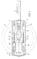
- Said lock 24, shown in detail in the figures 5 and 6, is substantially constituted by: an internally hollow body 3 which houses as internal components a fixed part 9 having a same external profile as the internal profile 9 of the key 5; a rotating part 11, arranged under said fixed part 9, having the same profile as said fixed part and integral with a lower cylindrical element 13 having the base surface 15 inclined; and a pawl 17, axially pushed against the inclined lower surface 15 of the lower element 13 by a spring 19 housed in a suitable seat 21.
- the key 5 for said lock is constituted by: a first lower part 31 having the same profile 9 as the fixed part 9 of the hollow body 3 of the lock; a second cylindrical part 33 with a diameter greater than the circumference circumscribed to the fixed part 9 and able to rotate, once the key has been put, around said shaped fixed part 9, internal to the hollow body 3; and a third upper part 37, analogous to the part 31, to which an external ring 35, or handle, is applied and by means of which it is possible to operate the key 5.
- the shape of the lower part 31 of the key 5, the shape of the fixed part 9 and of the rotating part 11 of the lock 24 is, in this embodiment, pentagonal with curved edges.
- the unlocking and the locking of the lock itself is caused by an half turn of the inclined base surface 15 of the lower element 13 acting on the pawl 17, pushed by the spring 19.
- the lock 24 is therefore locked when the pawl 17 is raised, and is unlocked when the pawl 17 is down.
- Said first means 12, able to engage with the rim 10 of said steering wheel, are fixed with respect to said primary part 4 and comprise at least an L-bent element, while said second means 14 are longitudinally movable with respect to the body of the device and comprise at least an L-bent element.
- Said second means 14 are connected by means of a kinematic mechanism 16, 18, 20, with the rotation of said secondary part 6 so that, when said secondary part 6 is rotated from a rest position in which it overlaps the primary part 4, to the working position, said second means 14 engage with the rim 10 of the steering wheel, securing said primary part 4 to said steering wheel.
- Said second means 14 comprise two L-bent elements arranged at such a distance that they can comprise on the inside a spoke of said steering wheel.
- a plate 36 able to externally cover a portion of said rim in correspondence with said second means 14, in order to prevent the cutting of the rim near said spoke.
- Said kinematic mechanism 16, 18, 20 comprises means 20, 22 for adjusting the distance between said first 12 and said second 14 means able to engage with the rim 10 of said steering wheel, for adapting to steering wheels of different diameters.
- Said kinematic mechanism comprises an eccentric wheel 16 connected with the rotation axis of said secondary part 6, which pushes a series of rods 18a, 18b connected with said second means 14 and able to engage with the rim 10 of said steering wheel.
- a second embodiment of an anti-theft device realised according to the present invention is shown in the figures from 8 to 11.
- the device shown in the figures from 8 to 11 is substantially constituted by an elongated body 101 which comprises a primary part 103 provided with first 107 and second 105 means able to engage with respective diametrically opposite portions of the rim 109 of a steering wheel, and a secondary part 111 able to make the primary part 103 longer, in order to prevent the rotation of the steering wheel 109 of a vehicle.
- the primary part 103 and the secondary part 111 are hinged between them by means of a hinge pin 113 so that said secondary part 111 can rotate with respect to said primary part 103 on a plane substantially parallel to the plane of the rim 109 of the steering wheel, for assuming a working position in which the two parts 103 and 111 are substantially aligned on two parallel planes.
- a cylindrical key lock 24 is provided in correspondence with the hinge zone of said two parts 103 and 111 in order to block the rotation of said secondary part 11 with respect to said primary part 3.
- the lock 24 is of the type previously described with reference to the figures 5 and 6.
- a disc element 117 Integral with the hinge pin 113 and with the secondary part 111 is arranged a disc element 117, eccentric with respect to said pin 113, which engages in 119 with another substantially linear element 121, slidingly secured in 123 to the lower part of the primary part 103.
- Said engagement is constituted by an edge 125 of the disc element 117, normal to the plane of said disc 117, which engages into a groove 127 provided in the near end of the element 121, said end being provided as an arc of a circle and arranged convex with respect to said disc element 117.
- Said first 107 and second 105 means, able to engage with the rim 109 of the steering wheel are U-arranged and are hinged, in the points 129 and 131, to the two ends of the primary part 103 having the greatest reciprocal distance.
- the other ends 135 and 133 of the U of said first 107 and second 105 means are each equipped with a notch 139 and 137, able to couple with respective side walls of a plate 141, which are provided integral with and arranged under the secondary part 111 of the device, and with the side walls of the elongated body 121.
- said U-elements 107 and 105 are provided in a number of four, two on each side, so that the rim 109 of the steering wheel remains blocked from said elements in four points.
- the U-elements 105 are secured to a plate 143 slidingly arranged in the longitudinal sense of the primary part 103, in order to adapt the device to the width of the steering wheel.
- the sliding of the plate 143 is obtained through appropriate slits which allow the sliding along said slits of the securing means of the plate to the primary part 103.
Landscapes
- Engineering & Computer Science (AREA)
- Mechanical Engineering (AREA)
- Steering Controls (AREA)
- Lock And Its Accessories (AREA)
Abstract
Cylindrical key lock (24) for an anti-theft device for preventing the rotation of the
steering wheel of a vehicle, comprising an internally hollow body (3) housing a
fixed part (9) having an external profile identical to the internal profile of a first
lower part (31) of the key (5), a rotating part (11), arranged under said fixed
part (9) and having the same profile, integral with a lower cylindrical element
(13) having the base surface (15) inclined, and a pawl (17), axially pushed by a
spring (19) against the inclined lower surface (15) of the lower cylindrical
element (13), the key (5) being moreover provided with a cylindrical internal
part (33), on the top of the lower part (31), able to rotate around the fixed part
(9) of the lock.
Description
- The present invention relates to an anti-theft device for vehicles; in particular, it refers to a cylindrical key lock for an anti-theft device of the type that is secured to the steering wheel of a vehicle and that prevents the rotation of the steering wheel.
- Devices of this type are known: for instance, the patent US 5,138,853 describes an anti-theft device comprising a rod member that is secured to the steering wheel by means of two locks closing ring-like on the rim of the steering wheel. The length of the rod member is such to prevent the rotation of the steering wheel, prevented by the obstacles present inside the vehicle, windscreen, uprights and so on.
- Likewise are known cylindrical key locks, in particular for vehicles; generally they consist of a cylindrical body provided with grooves and/or protrusions suitable for coupling with corresponding complementary protrusions and grooves provided in another cylindrical body, hollowed, in which said first cylindrical body is inserted; both are provided with positioning elements which, when positioned in a predetermined position, allow the movable cylindrical body to rotate relatively to the fixed cylindrical body, and therefore the operation of the lock.
- The variety of said locks is very wide, all of them are however too complex to be easily applied to a device which must be simple and necessarily inexpensive as an anti-theft device for preventing the rotation of the steering wheel.
- It is an object of the present invention to realise a cylindrical key lock suited to be applied to an anti-theft device for vehicles, as for example to an anti-theft device applicable to the steering wheel of a vehicle, that is to an object or device in which the complexity of the key lock is not an excessive load for the realisation of the same.
- This and other objects are obtained by a cylindrical key lock realised according to the invention, as claimed in the hereby attached claims.
- The invention will be now described in detail with particular reference to the attached drawings showing a preferred embodiment of the invention, wherein:
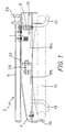
- figure 1 is a side sectional view of a first embodiment of an anti-theft device realised according to the present invention, in closed position;
- figure 2 is a side sectional view of the anti-theft device of figure 1, in open position;
- figure 3 is a top internal view of the anti-theft device of figure 1, in open position;
- figure 4 is a top internal view of the anti-theft device of figure 1, in different intermediate positions;
- figures 5 and 6 show in particular a section of the lock, with its relative key, of an anti-theft device realised in accordance with the present invention;
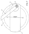
- figure 7 is a top view of the anti-theft device of figure 1, in an intermediate position;
- figure 8 is an elevational side view of a second embodiment of a device realised according to the present invention, in extended position;
- figure 9 is top plan view of the device of figure 8;
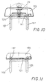
- figure 10 is a right front view of the device of figure 8; and
- figure 11 is a left front view of the device of figure 8.
- With reference to figure 1, an
anti-theft device 2, realised according to a first embodiment of the present invention and able to be coupled with a steering wheel of a vehicle, is constituted by an elongated body provided with means for securing said steering wheel to therim 10, said elongated body comprising a primary part 4 provided with first 12 and second 14 means able to engage with respective diametrically opposite parts of therim 10 of said steering wheel, and asecondary part 6 able to make said primary part 4 longer in order to prevent the rotation of said steering wheel. - Said primary part 4 and said
secondary part 6 are hinged between them by means of ahinge pin 8, so that saidsecondary part 6 can rotate with respect to said primary part 4 on a plane substantially parallel to the plane of therim 10 of the steering wheel, for assuming a working position in which the twoparts 4, 6 are substantially aligned. - A
cylindrical key lock 24 is provided in correspondence with the hinge zone of said twoparts 4, 6 in order to block the rotation of saidsecondary part 6 with respect to said primary part 4. - Said
lock 24, shown in detail in the figures 5 and 6, is substantially constituted by: an internallyhollow body 3 which houses as internal components afixed part 9 having a same external profile as theinternal profile 9 of thekey 5; arotating part 11, arranged under saidfixed part 9, having the same profile as said fixed part and integral with a lowercylindrical element 13 having thebase surface 15 inclined; and apawl 17, axially pushed against the inclinedlower surface 15 of thelower element 13 by aspring 19 housed in asuitable seat 21. - In turn, the
key 5 for said lock is constituted by: a firstlower part 31 having thesame profile 9 as thefixed part 9 of thehollow body 3 of the lock; a secondcylindrical part 33 with a diameter greater than the circumference circumscribed to thefixed part 9 and able to rotate, once the key has been put, around said shapedfixed part 9, internal to thehollow body 3; and a thirdupper part 37, analogous to thepart 31, to which anexternal ring 35, or handle, is applied and by means of which it is possible to operate thekey 5. - The shape of the
lower part 31 of thekey 5, the shape of thefixed part 9 and of therotating part 11 of thelock 24 is, in this embodiment, pentagonal with curved edges. - The unlocking and the locking of the lock itself is caused by an half turn of the
inclined base surface 15 of thelower element 13 acting on thepawl 17, pushed by thespring 19. Thelock 24 is therefore locked when thepawl 17 is raised, and is unlocked when thepawl 17 is down. - Said first means 12, able to engage with the
rim 10 of said steering wheel, are fixed with respect to said primary part 4 and comprise at least an L-bent element, while saidsecond means 14 are longitudinally movable with respect to the body of the device and comprise at least an L-bent element. - Said
second means 14 are connected by means of akinematic mechanism secondary part 6 so that, when saidsecondary part 6 is rotated from a rest position in which it overlaps the primary part 4, to the working position, saidsecond means 14 engage with therim 10 of the steering wheel, securing said primary part 4 to said steering wheel. - Said second means 14 comprise two L-bent elements arranged at such a distance that they can comprise on the inside a spoke of said steering wheel.
- It is further provided a
plate 36, able to externally cover a portion of said rim in correspondence with saidsecond means 14, in order to prevent the cutting of the rim near said spoke. - Said
kinematic mechanism rim 10 of said steering wheel, for adapting to steering wheels of different diameters. - When said
secondary part 6 is in a position different from the working position, said adjustment is accessible from the outside of the device by means of aslit 26. - Said kinematic mechanism comprises an
eccentric wheel 16 connected with the rotation axis of saidsecondary part 6, which pushes a series ofrods second means 14 and able to engage with therim 10 of said steering wheel. - When the
secondary part 6 is brought back into the rest position for removing the anti-theft device from the steering wheel, a pair ofsprings rods 18b and thus the second means 14. - A second embodiment of an anti-theft device realised according to the present invention is shown in the figures from 8 to 11.
- The device shown in the figures from 8 to 11 is substantially constituted by an
elongated body 101 which comprises aprimary part 103 provided with first 107 and second 105 means able to engage with respective diametrically opposite portions of therim 109 of a steering wheel, and asecondary part 111 able to make theprimary part 103 longer, in order to prevent the rotation of thesteering wheel 109 of a vehicle. - The
primary part 103 and thesecondary part 111 are hinged between them by means of ahinge pin 113 so that saidsecondary part 111 can rotate with respect to saidprimary part 103 on a plane substantially parallel to the plane of therim 109 of the steering wheel, for assuming a working position in which the twoparts - A
cylindrical key lock 24 is provided in correspondence with the hinge zone of said twoparts secondary part 11 with respect to saidprimary part 3. - The
lock 24 is of the type previously described with reference to the figures 5 and 6. - Integral with the
hinge pin 113 and with thesecondary part 111 is arranged adisc element 117, eccentric with respect to saidpin 113, which engages in 119 with another substantiallylinear element 121, slidingly secured in 123 to the lower part of theprimary part 103. - Said engagement is constituted by an
edge 125 of thedisc element 117, normal to the plane of saiddisc 117, which engages into agroove 127 provided in the near end of theelement 121, said end being provided as an arc of a circle and arranged convex with respect to saiddisc element 117. - Said first 107 and second 105 means, able to engage with the
rim 109 of the steering wheel are U-arranged and are hinged, in thepoints primary part 103 having the greatest reciprocal distance. - The
other ends notch plate 141, which are provided integral with and arranged under thesecondary part 111 of the device, and with the side walls of theelongated body 121. - It is to be noted that said U-elements 107 and 105 are provided in a number of four, two on each side, so that the
rim 109 of the steering wheel remains blocked from said elements in four points. - It is to be observed that the
U-elements 105 are secured to aplate 143 slidingly arranged in the longitudinal sense of theprimary part 103, in order to adapt the device to the width of the steering wheel. - The sliding of the
plate 143 is obtained through appropriate slits which allow the sliding along said slits of the securing means of the plate to theprimary part 103.
Claims (4)
- Cylindrical key lock (24) for an anti-theft device (2; 101) for preventing the rotation of the steering wheel of a vehicle, said lock (24) comprising an internally hollow body (3) which houses internal components of the lock, characterised in that said internal components comprise:a fixed part (9) having an external profile identical to the internal profile of a first lower part (31) of the key (5);a rotating part (11), arranged under said fixed part (9), having the same profile as said fixed part, integral with a lower cylindrical element (13) having the base surface (15) inclined;a pawl (17), axially pushed by a spring (19) against the inclined lower surface (15) of said lower cylindrical element (13), so that, during rotation of said lower cylindrical element (13), said pawl (17) is driven by said inclined base surface (15) moving away from the body (3) of the lock.
- Cylindrical key lock (24) according to claim 1, wherein said key (5) comprises:a first lower part (31), having an internal profile identical to the profile of the fixed part (9) of the body (3) of the lock (24);a second part (33), cylindrical, with a diameter greater than the circumference circumscribed to the fixed part (9) and able to rotate, when the key (5) has been inserted in the lock (24), around said shaped fixed part (9), internal to the hollow body (3) of the lock (24);an external ring (35), or handle, by means of which it is possible to operate the key (5).
- Cylindrical key lock (24) according to claim 2, wherein the unlocking and the locking of the lock itself is caused by an half turn of the inclined base surface (15) of the lower element (13) acting on the pawl (17), pushed by the spring (19), said lock (24) being locked when said pawl (17) is raised, and being unlocked when said pawl (17) is down.
- Cylindrical key lock (24) according to any of the preceding claims, wherein the shape of the lower part (31) of the key (5), the shape of the fixed part (9) and of the rotating part (11) of the lock (24) is pentagonal with curved edges.
Applications Claiming Priority (5)
| Application Number | Priority Date | Filing Date | Title |
|---|---|---|---|
| ITTO000262 | 2000-03-20 | ||
| IT2000TO000262A IT1319981B1 (en) | 2000-03-20 | 2000-03-20 | Steering wheel mounted antitheft device for vehicle has primary body that is engageable with opposite portions of rim of steering wheel and which is aligned with extending secondary body when assuming use state |
| IT2000TO001167 IT1321105B1 (en) | 2000-12-15 | 2000-12-15 | Steering wheel mounted antitheft device for vehicle has primary body that is engageable with opposite portions of rim of steering wheel and which is aligned with extending secondary body when assuming use state |
| ITTO001167 | 2000-12-15 | ||
| EP01105677A EP1136332A3 (en) | 2000-03-20 | 2001-03-07 | Steering wheel mounted anti-theft device |
Related Parent Applications (1)
| Application Number | Title | Priority Date | Filing Date |
|---|---|---|---|
| EP01105677A Division EP1136332A3 (en) | 2000-03-20 | 2001-03-07 | Steering wheel mounted anti-theft device |
Publications (1)
| Publication Number | Publication Date |
|---|---|
| EP1155930A2 true EP1155930A2 (en) | 2001-11-21 |
Family
ID=26332862
Family Applications (2)
| Application Number | Title | Priority Date | Filing Date |
|---|---|---|---|
| EP01105677A Withdrawn EP1136332A3 (en) | 2000-03-20 | 2001-03-07 | Steering wheel mounted anti-theft device |
| EP01117192A Withdrawn EP1155930A2 (en) | 2000-03-20 | 2001-03-07 | Cylindrical key lock for anti-theft device for vehicle steering wheel immobilisation |
Family Applications Before (1)
| Application Number | Title | Priority Date | Filing Date |
|---|---|---|---|
| EP01105677A Withdrawn EP1136332A3 (en) | 2000-03-20 | 2001-03-07 | Steering wheel mounted anti-theft device |
Country Status (1)
| Country | Link |
|---|---|
| EP (2) | EP1136332A3 (en) |
Family Cites Families (3)
| Publication number | Priority date | Publication date | Assignee | Title |
|---|---|---|---|---|
| FR2457793A1 (en) * | 1979-05-30 | 1980-12-26 | Blasi Francesco | Mechanical antitheft device for vehicle - has two arms with hooks to steering wheel one long enough to prevent rotation of wheel |
| US5138853A (en) * | 1991-09-24 | 1992-08-18 | Chen Ruei Mei | Antitheft lock for a vehicle |
| US5755123A (en) * | 1995-10-10 | 1998-05-26 | Winner International Royalty Corporation | Steering wheel protection device |
-
2001
- 2001-03-07 EP EP01105677A patent/EP1136332A3/en not_active Withdrawn
- 2001-03-07 EP EP01117192A patent/EP1155930A2/en not_active Withdrawn
Also Published As
| Publication number | Publication date |
|---|---|
| EP1136332A3 (en) | 2002-07-10 |
| EP1136332A2 (en) | 2001-09-26 |
Similar Documents
| Publication | Publication Date | Title |
|---|---|---|
| AU637691B2 (en) | An anti-theft steering wheel lock for automobiles | |
| US5678433A (en) | Antitheft device for locking the steering wheel of any kind of vehicle | |
| US4760718A (en) | Wheel lock for vehicles | |
| US5031428A (en) | Two stage automobile steering lock | |
| US5005388A (en) | Automobile steering lock | |
| US5487285A (en) | Lock with rod-shaped elements | |
| US5131245A (en) | Automobile steering lock | |
| US5488845A (en) | Single insertion locking U-shaped padlock structure | |
| HK1002322B (en) | Lock | |
| CA2322245A1 (en) | Automotive steering wheel anti-theft device | |
| US7210319B2 (en) | Multifunctional vehicle lock | |
| HK1002533B (en) | Antitheft device for vehicles | |
| US5165264A (en) | Telescopic lock device for a steering wheel in an automobile | |
| EP1155930A2 (en) | Cylindrical key lock for anti-theft device for vehicle steering wheel immobilisation | |
| US5706681A (en) | Antitheft locking device for a vehicle | |
| WO1986005150A1 (en) | A vehicle road wheel locking device | |
| US6257630B1 (en) | Tubular lock with adjustable backset | |
| ITTO980396A1 (en) | STEERING LOCKING DEVICE FOR A VEHICLE STEERING GROUP. | |
| US4301669A (en) | Two anti-theft locks | |
| US5653132A (en) | Steering wheel locking apparatus | |
| CA2179342A1 (en) | Cam lock | |
| US6176110B1 (en) | Vehicle steering wheel locking device | |
| GB1577316A (en) | Ventilator assemblies for public service and other vehicles | |
| US5582045A (en) | Anti-theft device for attachment to a steering wheel in a motor vehicle | |
| EP0883531B1 (en) | Motor vehicle anti-theft device |
Legal Events
| Date | Code | Title | Description |
|---|---|---|---|
| PUAI | Public reference made under article 153(3) epc to a published international application that has entered the european phase |
Free format text: ORIGINAL CODE: 0009012 |
|
| AC | Divisional application: reference to earlier application |
Ref document number: 1136332 Country of ref document: EP |
|
| AK | Designated contracting states |
Kind code of ref document: A2 Designated state(s): AT BE CH CY DE DK ES FI FR GB GR IE IT LI LU MC NL PT SE TR |
|
| AX | Request for extension of the european patent |
Free format text: AL;LT;LV;MK;RO;SI |
|
| STAA | Information on the status of an ep patent application or granted ep patent |
Free format text: STATUS: THE APPLICATION HAS BEEN WITHDRAWN |
|
| 18W | Application withdrawn |
Effective date: 20031219 |