EP1155792A1 - Circular saw - Google Patents
Circular saw Download PDFInfo
- Publication number
- EP1155792A1 EP1155792A1 EP00900901A EP00900901A EP1155792A1 EP 1155792 A1 EP1155792 A1 EP 1155792A1 EP 00900901 A EP00900901 A EP 00900901A EP 00900901 A EP00900901 A EP 00900901A EP 1155792 A1 EP1155792 A1 EP 1155792A1
- Authority
- EP
- European Patent Office
- Prior art keywords
- saw
- tips
- circular saw
- tip
- cutting
- Prior art date
- Legal status (The legal status is an assumption and is not a legal conclusion. Google has not performed a legal analysis and makes no representation as to the accuracy of the status listed.)
- Granted
Links
Images







Classifications
-
- B—PERFORMING OPERATIONS; TRANSPORTING
- B27—WORKING OR PRESERVING WOOD OR SIMILAR MATERIAL; NAILING OR STAPLING MACHINES IN GENERAL
- B27B—SAWS FOR WOOD OR SIMILAR MATERIAL; COMPONENTS OR ACCESSORIES THEREFOR
- B27B33/00—Sawing tools for saw mills, sawing machines, or sawing devices
- B27B33/02—Structural design of saw blades or saw teeth
- B27B33/08—Circular saw blades
-
- Y—GENERAL TAGGING OF NEW TECHNOLOGICAL DEVELOPMENTS; GENERAL TAGGING OF CROSS-SECTIONAL TECHNOLOGIES SPANNING OVER SEVERAL SECTIONS OF THE IPC; TECHNICAL SUBJECTS COVERED BY FORMER USPC CROSS-REFERENCE ART COLLECTIONS [XRACs] AND DIGESTS
- Y10—TECHNICAL SUBJECTS COVERED BY FORMER USPC
- Y10T—TECHNICAL SUBJECTS COVERED BY FORMER US CLASSIFICATION
- Y10T83/00—Cutting
- Y10T83/929—Tool or tool with support
- Y10T83/9319—Toothed blade or tooth therefor
Definitions
- the present invention relates to a circular saw used for woodworking and similar work, and more particularly, to the shape of side cutting edges of tips fixed to teeth of the circular saw.
- the present invention solves the above-described problems, and its object is to provide a circular saw which can reduce the surface roughness of a cut surface of a soft material such as wood formed though cutting.
- the first invention provides a circular saw having tips fixed to a plurality of teeth projecting radially outward from the outer circumference of a disk-shaped saw blade body, characterized in that a side cutting edge, which has a inflexion point at a portion at which the side cutting edge projects laterally to the greatest width in a front view of the tip, has a negative radial clearance angle of not less than -1° but less than 0° in the vicinity of the inflexion point of the side cutting edge and on the outer circumferential side with respect to the inflexion point, and a positive radial clearance angle of greater than 0° but less than 1° in the vicinity of the inflexion point of the side cutting edge and on the inner circumferential side with respect to the inflexion point.
- the side cutting edge is formed to assume a negative radial clearance angle on the outer circumferential side with respect to the inflexion point and a positive radial clearance angle on the inner circumferential side with respect to the inflexion point, there can be obtained a cut surface of lower surface roughness (greater smoothness) as compared with that obtained by use of a conventional saw.
- the radial clearance angle of 0° is not preferable, because the cut surface is likely to be burned.
- the outer-circumferential-side radial clearance angle is less than -1° or when the inner-circumferential-side radial clearance angle is greater than 1°, surface roughness increases.
- the second invention provides a circular saw having tips fixed to a plurality of teeth projecting radially outward from the outer circumference of a disk-shaped saw blade body, characterized in that the plurality of tips include in combination the tips according to the first invention and second tips, wherein the second tips have an outer circumferential height greater than that of the tips according to the first invention and a maximum width narrower than that of the tips according to the first invention.
- the tips according to the first invention and the second tips are combined so as to perform divided cutting such that peripheral cutting is performed mainly by the second tips, and a rough cut surface formed as a result of cutting by the second tips is subjected to surface cutting performed by the tips of the first invention.
- a rough cut surface formed as a result of cutting by the second tips is subjected to surface cutting performed by the tips of the first invention.
- the third invention is characterized in that a mechanism having a higher damping capability is equipped to the saw blade body of the above-described circular saw such that at least a portion of the mechanism is present in an area between a concentric circle having a diameter 80% the outer diameter of the circular saw and a concentric circle having a diameter 100% the outer diameter of the circular saw.
- This configuration prevents vibration of the saw blade body of the circular saw. As a result, peculiar cutting noise generated during cutting upon use of the tips can be suppressed, and cut surface of high quality can be obtained.
- FIG. 1 shows enlarged front and side views of a tip of a circular saw according to a first embodiment of the present invention.
- FIG. 2 shows enlarged front and side views of tips of circular saws according to modifications of the first embodiment.
- FIG. 3 is an explanatory diagram showing a cutting state in the case in which a rake face of a tip has a face bevel angle.
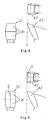
- FIG. 4 shows enlarged front, plan, and side views of a tip of a circular saw which has a inflexion rake face having no face bevel angle.
- FIG. 5 shows enlarged front, plan, and side views of a tip which has a inflexion rake face having a face bevel angle that is constant irrespective of position in the radial direction of the saw.
- FIG. 1 shows enlarged front and side views of a tip of a circular saw according to a first embodiment of the present invention.
- FIG. 2 shows enlarged front and side views of tips of circular saws according to modifications of the first embodiment.
- FIG. 3 is an
- FIG. 6 shows enlarged front, plan, and side views of a tip which has a inflexion rake face having a face bevel angle that changes with the radial direction of the saw.
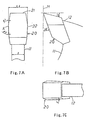
- FIG. 7 shows enlarged front, plan, and side views of a tip of a circular saw of Test Example 1.
- FIG. 8 shows graphs representing the cross-sectional profile of a workpiece cut by use of a tipped saw of the present invention and the cross-sectional profile of a workpiece cut by use of a conventional tipped saw, which profiles were obtained in Test Example 2.
- FIG. 8 shows graphs representing the cross-sectional profile of a workpiece cut by use of a tipped saw of the present invention and the cross-sectional profile of a workpiece cut by use of a conventional tipped saw, which profiles were obtained in Test Example 2.
- FIG. 9 shows graphs representing the cross-sectional profile of a workpiece cut by use of the tipped saw of the present invention and the cross-sectional profile of a workpiece cut by use of a conventional tipped saw, which profiles were obtained in Test Example 3.
- FIG. 10 shows enlarged front and side views of a tip of a circular saw of Test Example 4.
- FIG. 11 shows a graph representing the relationship between material feed rate and net cutting power of a tipped saw as obtained in Test Example 5.
- FIG. 12 shows a graph representing the cross-sectional profile of a workpiece cut by use of the tipped saw of the present invention as obtained in Test Example 5.
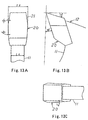
- FIG. 13 shows enlarged front, side, and plan views of a tip of a circular saw of Test Example 6.
- FIG. 14 shows a graph representing the relationship between noise level and ratio da/do (outer diameter of a vibration-absorbing plate/outer diameter of a tipped saw) as obtained in Test Example 6.
- FIG. 15 is a side view showing the entirety of the circular saw of Test Example 6.
- FIG. 16 shows a graph representing the relationship between noise level and rotational speed of a circular saw as obtained in Test Example 7.
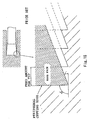
- FIG. 17 shows an enlarged front view of a tip in which a inflexion portion of a side cutting edge has a deformed shape.
- FIG. 18 is an explanatory diagram which is used for calculating the surface roughness of a material cut by use of a conventional circular saw.
- FIGS. 1(a) and 1(b) show a tip, which is a main portion of a tipped circular saw according to a first embodiment, by means of a front view (view obtained through projecting the tip on a plane M including the rotational axis of the circular saw and the tip of the tip) and a side view.
- a tip 20 is provided on a front face 12a, with respect to the rotational direction, of each tooth 12 projecting outward from the outer circumference of a disk-shaped saw blade body 11 of a circular saw (in FIG. 1, the circular saw has an outer diameter of 255 mm, a saw blade body thickness of 3 mm, and 40 teeth).
- the tip 20 inclines slightly toward the front side with respect to the rotational direction to thereby form a rake angle (20° in the illustrated example).
- a peripheral cutting edge 21 is flat and has a peripheral clearance angle (15° in the illustrated example). As shown in FIG.
- each side cutting edge 22 of the tip 20 has a inflexion point K at a position which is offset from the outer circumference toward the inner circumference side by a predetermined distance (1.2 mm in the illustrated example).
- the tip 20 projects laterally to have the greatest width (4.4 mm in the illustrated example).
- the side cutting edge 22 forms straight lines that extend from the inflexion point K toward opposite sides each other.
- the radial clearance angle on the outer circumferential side of the inflexion point K is negative (-30' in the illustrated example), and the radial clearance angle on the inner circumferential side of the inflexion point K is positive (10' in the illustrated example).
- a distance L between an outer circumference end portion 21A and the inflexion point K as measured along the width direction is about 0.01 mm (about 10 ⁇ m). Therefore, cracks and depressions generated by the outer circumference end portion 21A are cut over a length L of their entire heights.
- the theoretical surface roughness Rmax of a cut surface of a wood workpiece cut by use of a circular saw having the tip 20 is 76.4 ⁇ m, which is a value obtained through subtraction of the length L from the surface roughness Rmax of 86.4 ⁇ m above-mentioned for the case in which a wood workpiece was actually cut by use of a conventional circular saw.
- a peripheral cutting edge 31 of a tip 30 whose side cutting edges have positive and negative radial clearance angles is formed into a concave shape (FIG. 2(a)) or a convex shape (FIG. 2(b), which shape is symmetric with respect to the widthwise direction.
- the peripheral cutting edge 31 of the concave shape was found to further reduce the generation of cracks and depressions that extend outward in the thickness direction of the saw. Further, since the peripheral cutting edge 31 of the concave shape improves the stability of the tip 30 in terms of moving straight with respect to the material feed direction to thereby suppress side run-out, the rake surface can be finished much better.
- tips which fall within the scope of the present invention but differ from the above-described embodiments will be described.
- Each of the tips shown in the above-described embodiments has a single rake face.
- tips T1 to T3 each of which has two flat rake faces 41 on either side of the inflexion point K, will be described.
- FIG. 4 shows a tip T1 which has zero face bevel angle
- FIG. 5 shows a tip T2 which has a face bevel angle that is constant along the radial direction of the saw
- FIG. 6 shows a tip T3 which has a face bevel angle that varies along the radial direction of the saw.
- the rake face has a face bevel angle.
- the present embodiment is directed to a circular saw in which the tip 20 (or the tip 30) of the above-described embodiment and a conventional tip are attached in combination to the teeth 12 of the saw blade body 11, the conventional tip having a rake angle and a peripheral clearance angle, and an outer-circumferential height greater than that of the tip 20, as well as a maximum width narrower than that of the tip 20.
- the tips of the above embodiment and the conventional tips may be equal in number or may differ in number. Further, the tips of the above embodiment and the conventional tips may be arranged in accordance with a certain sequence or arbitrarily.
- peripheral cutting is effected mainly by the conventional tip, and a rough cut surface formed as a result of the cutting by the conventional tip is cut mainly by the tip 20. Since the conventional tip and the tip 20 cut the cutting area in a divided manner, cutting resistance can be reduced, and a well-finished cut surface can be obtained through action of the tip 20.
- each tip had a rake angle of 20°, a side clearance angle of 3°, and a peripheral clearance angle of 15°.
- An outer-circumferential-side negative radial clearance angle ⁇ 1 and an inner-circumferential-side positive radial clearance angle ⁇ 2 shown in the front view were varied among the five types as shown in Table 1, which will be described below.
- 40 tips were fixed to teeth 12 of a saw blade body 11 having an outer diameter of 255 mm, a saw kerf width of 4.4 mm, and a saw blade body thickness of 3 mm.
- Cutting was performed at a rotational speed (of the tipped saw) of 5000 rpm and a material feed rate of 10 m/min.
- the material of a workpiece was wood (spruce: conifer), and longitudinal cutting (cutting along the direction of fibers) was performed.
- Evaluation items were center-line average roughness Ra, ten-points average roughness Rz, maximum height Rmax, appearance, and texture of cut surface. Quality of cut surface was judged through total evaluation of these items. Appearance and texture were evaluated, while the cut surface obtained through use of the conventional tipped saw was used as a standard (rank: C).
- the five tipped saws of the present invention provided results which are far better than those obtained through use of the conventional tipped saw.
- test samples of tips there were prepared forty tips each having the same shape as that of the test samples used in Test Example 1.
- Each tip had a rake angle of 20°, a side clearance angle of 3°, and a peripheral clearance angle of 15°; and an outer-circumferential-side negative radial clearance angle of -10' and an inner-circumferential-side radial clearance angle of 30', both measured in the front view.
- the forty tips were fixed to a saw blade body having an outer diameter of 255 mm, a saw kerf width of 4.4 mm, and a saw blade body thickness of 3 mm in order to obtain a tipped saw of the present invention.
- a conventional tipped saw having conventional tips attached thereto was prepared as a comparative sample.
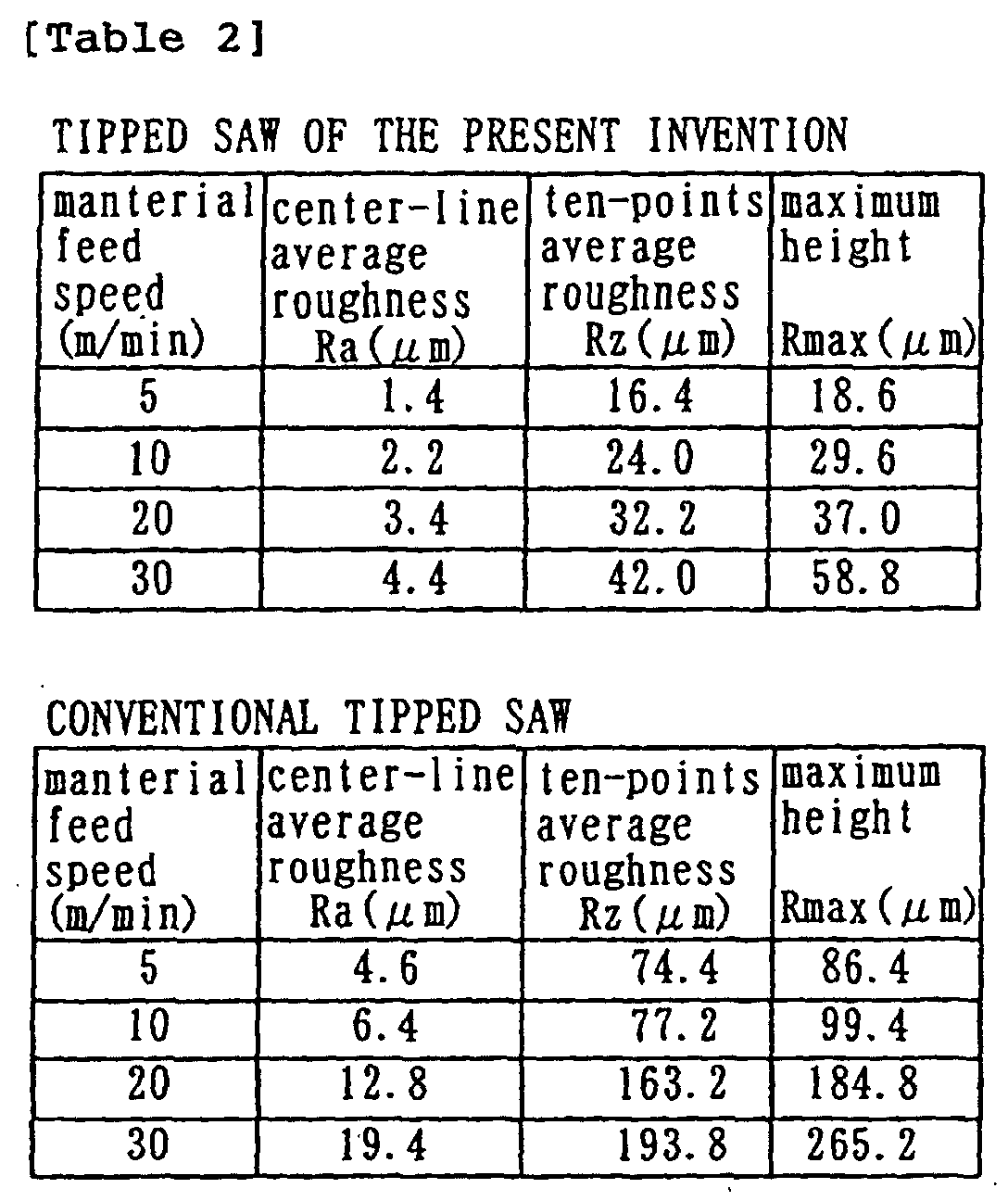
- Cutting was performed at a rotational speed (of the tipped saw) of 4000 rpm and a material feed rate of 5, 10, 20, or 30 m/min.
- the material of a workpiece was wood (pinus radiata: conifer), and transverse cutting (cutting along a direction perpendicular to the fiber direction) was performed.
- Evaluation items were center-line average roughness Ra, ten-points average roughness Rz, and maximum height Rmax of cut surface. Table 2 shows test results; and FIG. 8 shows the cross-sectional profile of the workpiece cut at a material feed rate of 20 m/min.
- test sample achieved greatly smaller values than those obtained by use of the conventional tipped saw.
- test sample achieved a better result, with a clear difference from the result obtained though use of the conventional tipped saw.
- the test sample achieved greatly smaller values than those obtained by use of the conventional tipped saw.
- Japanese oak contains vessels of large diameter
- the values of surface roughness becomes relatively large, even though the remaining portion is flat, so that the difference from the case of the conventional tipped saw may decrease in some cases.
- vessels of large diameter could be identified more clearly as compared with the case of use of the conventional tipped saw, because, in the case of use of the test sample, the cut surface is flat except for vessels of large diameter.
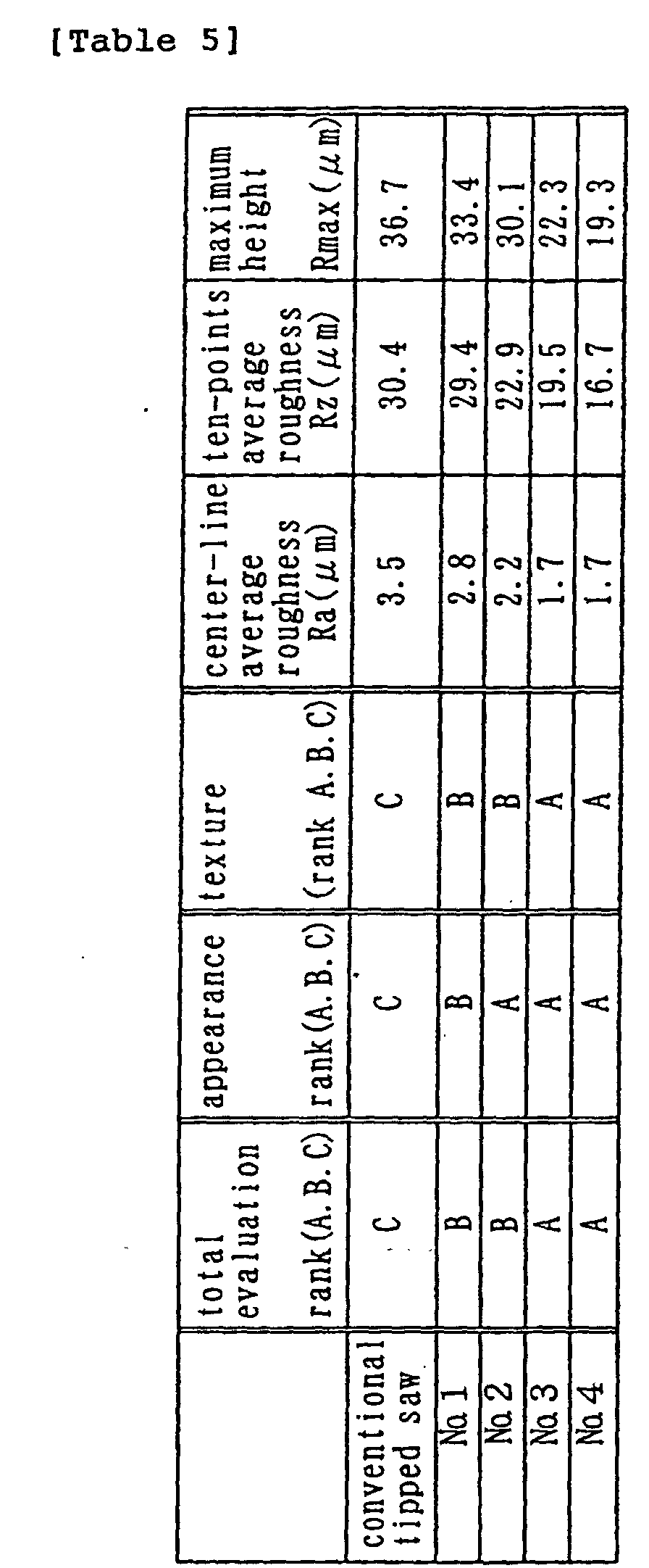
- test samples No. 1 to No. 4 of tips were prepared.
- each sample tip 50 had two cutting surfaces 51 (first rake angle ⁇ 1, second rake angle ⁇ 2).
- the shape of side cutting edges 52 as viewed in the front view; i.e., the outer-circumferential-side radial clearance angle ⁇ 1, the inner-circumferential-side radial clearance angle ⁇ 2, the side clearance angle, and the peripheral clearance angle were varied among the test samples No. 1 to No. 4 in accordance with combinations shown in Table 4.
- test sample No. 4 falls within the scope of the present invention.
- two rake faces having different rake angles were formed in order to provide a two-step radial clearance angle.
- 40 tips were fixed to teeth 12 of a saw blade body 11 having an outer diameter of 255 mm, a saw kerf width of 4.4 mm, and a saw blade body thickness of 3 mm.
- a conventional tipped saw was prepared as a comparative sample.
- Cutting was performed at a rotational speed (of the tipped saw) of 5000 rpm and a material feed rate of 10 m/min.
- the material of a workpiece was wood (spruce: conifer), and longitudinal cutting was performed.
- center-line average roughness Ra, and ten-points average roughness Rz, maximum height Rmax of cut surface were evaluated. Appearance and texture were evaluated, while the cut surface obtained through use of the conventional tipped saw was used as a standard (rank: C).
- the cut surface was assigned rank B.
- the test sample of the present invention (No. 4) and the test sample No. 3 having an outer-circumferential-side radial clearance angle of 0° provided good results for the respective items.
- the test samples No. 1 and 2 having two-step positive radial clearance angles provided better results as compared with the conventional tip, the results provided by the test samples No. 1 and 2 were clearly inferior to those provided by the test samples No. 3 and No. 4. Accordingly, cutting performance is not improved through mere employment of a two-step radial clearance angle, and the radial clearance angle on the outer circumferential side of the tip must be made negative. Although good cutting performance is obtained even in the case of the radial clearance angle on the outer circumferential side of the tip being zero, this makes the cut surface prone to suffering burn.
- tips for side-face finishing (hereinafter referred to as a finishing tip) had a rake angle of 20°, a side clearance angle of 3°, and a peripheral clearance angle of 15°; and an outer-circumferential-side radial clearance angle of -30' and an inner-circumferential-side radial clearance angle of 10', which defined the shape of side cutting edges as viewed in the front view.
- Tips for peripheral cutting (hereinafter referred to as rough tips) of a conventional shape had a positive radial clearance angle of 34', a rake angle of 20°, a side clearance angle of 1°, and a peripheral clearance angle of 15°.
- Twenty finish tips and twenty rough tips were arranged alternately and fixed to a saw blade body 11 having an outer diameter of 255 mm, a saw kerf width of 4.4 mm, and a saw blade body thickness of 3 mm in order to obtain a tipped saw of the present invention.
- a conventional tipped saw having a saw blade body 11 having the same dimensions and forty flat tips brazed to the saw blade body 11 was prepared as a comparative sample.
- Cutting was performed at a rotational speed (of the tipped saw) of 4000 rpm and a material feed rate of 5 or 10 m/min.
- the material of a workpiece was wood (Japanese oak: broad-leaf tree), and transverse cutting was performed. Evaluation items were center-line average roughness Ra, ten-points average roughness Rz, and maximum height Rmax of cut surface. Further, cutting power was measured. Table 6 shows measurement results.
- FIG. 11 shows the relationship between material feed rate and net cutting power; and
- FIG. 12 shows the cross-sectional profile of the workpiece cut at a material feed rate of 5 m/min.
- each tip 20 had a side clearance angle of 3°, a peripheral clearance angle of 15°, an outer-circumferential-side radial clearance angle of -30', and an inner-circumferential-side radial clearance angle of 30', as measured in the front view.
- the forty tips were brazed to a saw blade body 11 having an outer diameter of 255 mm, a saw kerf width of 2.0 mm, and a saw blade body thickness of 1.4 mm.
- the saw blade body 11 had four slots disposed at a constant pitch (center angle: 90°) and extending to the outer circumference of the saw blade body 11 (see reference numeral 61 shown in FIG.
- FIG. 14 shows test results.
- da represents the outer diameter of the vibration-absorbing plate; and do represents the outer diameter of the tipped saw.
- the noise level decreased as compared to the tipped saw having no annular vibration-absorbing plate.
- FIG. 16 shows test results.
- da represents the outer diameter of the vibration-absorbing plate; and do represents the outer diameter of the tipped saw.
- the ratio da/do was 0.88, the noise level could be reduced greatly as compared to the case of the ratio da/do being 0.712, within the rotational speed range of 4800 to 5300 rpm.
- each side cutting edge has an angular shape at the inflexion point K.
- This portion easily wears due to cutting, with the result that the radial clearance angle becomes zero or the portion assumes a rounded shape. Such wear is permissible if the length of the region in which the radial clearance angle is zero or the region of the rounded shape is not greater than the feed amount per tip (0.5 mm in this example), as shown in FIGS. 17(a) and 17(b).
- a hard film or hardened layer is preferably formed on at least side surfaces of the tips, or the tips are preferably made of a hard material such as polycrystallin diamond.
- the circular saw of the present invention is suitably used to cut a soft material such as wood to thereby reduce surface roughness and cutting resistance.
Landscapes
- Life Sciences & Earth Sciences (AREA)
- Engineering & Computer Science (AREA)
- Mechanical Engineering (AREA)
- Wood Science & Technology (AREA)
- Forests & Forestry (AREA)
- Sawing (AREA)
Abstract
Description


| outer radial clearance angle | inner radial clearence angle | rake angle | rake angle | side clearance angle | peripheral clearance angle | |
| 1 | 2 | ψ1 | ψ2 | |||
| No.1 | 30' | 60.1' | 20° | 30° | 3.41° | 15° |
| No.2 | 10' | 34' | 20° | 30° | 2.23° | 15° |
| No.3 | 0' | 34' | 20° | 30° | 3.27° | 15° |
| No.4 | -10' | 34' | 17.5° | 30° | 3.45° | 15° |
| manterial feed speed (m/min) | center-line average roughness Ra (µm) | ten-points average roughness Rz (µm) | maximum height Rmax (µm) | |
| tipped saw of the | 5 | 4.8 | 98.6 | 123.2 |
| 10 | 5.6 | 116.0 | 140.8 | |
| conventional tipped | 5 | 6.8 | 116.8 | 148.4 |
| 10 | 8.2 | 135.2 | 188.2 |
| outer diameter of a vibration-absorbing plate (mm) | hole diameter of a vibration-absorbing plate (mm) | thickness (mm) |
| 220 | 180 | 0.25 |
| 200 | 150 | 0.25 |
| 180 | 130 | 0.25 |
| 150 | 110 | 0.25 |
Claims (3)
- A circular saw having tips fixed to a plurality of teeth projecting radially outward from the outer circumference of a disk-shaped saw blade body, characterized in that a side cutting edge, which has a inflexion point at a portion at which the side cutting edge projects laterally to the greatest distance in a front view of the tip, has a negative radial clearance angle of not less than -1° but less than 0° in the vicinity of the inflexion point of the side cutting edge and on the outer circumferential side with respect to the inflexion point, and a positive radial clearance angle of greater than 0° but less than 1° in the vicinity of the inflexion point of the side cutting edge and on the inner circumferential side with respect to the inflexion point.
- A circular saw having tips fixed to a plurality of teeth projecting radially outward from the outer circumference of a disk-shaped saw blade body, characterized in that the plurality of tips include in combination the tips according to claim 1 and second tips having an outer circumferential height greater than that of the tips according to claim 1 and a maximum width narrower than that of the tips according to claim 1.
- A circular saw as described in claim 1 or 2, characterized in that a mechanism having a damping capability is equipped to the saw blade body of the circular saw such that at least a portion of the mechanism is present in an area between a concentric circle having a diameter 80% the outer diameter of the circular saw and a concentric circle having a diameter 100% the outer diameter of the circular saw.
Applications Claiming Priority (5)
| Application Number | Priority Date | Filing Date | Title |
|---|---|---|---|
| JP2181799 | 1999-01-29 | ||
| JP2181799 | 1999-01-29 | ||
| JP33282799 | 1999-11-24 | ||
| JP33282799A JP3170498B2 (en) | 1999-01-29 | 1999-11-24 | Circular saw |
| PCT/JP2000/000332 WO2000044539A1 (en) | 1999-01-29 | 2000-01-24 | Circular saw |
Publications (3)
| Publication Number | Publication Date |
|---|---|
| EP1155792A1 true EP1155792A1 (en) | 2001-11-21 |
| EP1155792A4 EP1155792A4 (en) | 2002-05-22 |
| EP1155792B1 EP1155792B1 (en) | 2013-02-27 |
Family
ID=26358937
Family Applications (1)
| Application Number | Title | Priority Date | Filing Date |
|---|---|---|---|
| EP20000900901 Expired - Lifetime EP1155792B1 (en) | 1999-01-29 | 2000-01-24 | Circular saw |
Country Status (5)
| Country | Link |
|---|---|
| US (1) | US6708594B1 (en) |
| EP (1) | EP1155792B1 (en) |
| JP (1) | JP3170498B2 (en) |
| CA (1) | CA2358990C (en) |
| WO (1) | WO2000044539A1 (en) |
Cited By (1)
| Publication number | Priority date | Publication date | Assignee | Title |
|---|---|---|---|---|
| WO2008135035A1 (en) * | 2007-05-08 | 2008-11-13 | Leitz Gmbh & Co. Kg | Tool for machining, particularly circular saw blade |
Families Citing this family (19)
| Publication number | Priority date | Publication date | Assignee | Title |
|---|---|---|---|---|
| US20060018782A1 (en) * | 2000-09-28 | 2006-01-26 | Mikronite Technologies Group, Inc. | Media mixture for improved residual compressive stress in a product |
| US20020078813A1 (en) * | 2000-09-28 | 2002-06-27 | Hoffman Steve E. | Saw blade |
| US20050279430A1 (en) * | 2001-09-27 | 2005-12-22 | Mikronite Technologies Group, Inc. | Sub-surface enhanced gear |
| JP2004122300A (en) * | 2002-10-03 | 2004-04-22 | Tenryu Saw Mfg Co Ltd | Rotary saw |
| CA2470208A1 (en) * | 2003-06-06 | 2004-12-06 | Camco Cutting Tools Ltd. | Saw tooth |
| US7273409B2 (en) * | 2004-08-26 | 2007-09-25 | Mikronite Technologies Group, Inc. | Process for forming spherical components |
| US20080022832A1 (en) * | 2006-07-27 | 2008-01-31 | Black & Decker Inc. | Saw blade for cutting cement board |
| USD559067S1 (en) | 2006-07-27 | 2008-01-08 | Black & Decker Inc. | Saw blade |
| USD553934S1 (en) * | 2007-03-07 | 2007-10-30 | Evolution Power Tools Limited | Circular saw blade |
| US20080257127A1 (en) * | 2007-04-17 | 2008-10-23 | The M. K. Morse Company | Saw blade |
| JP5951788B2 (en) | 2012-10-22 | 2016-07-13 | 兼房株式会社 | Tip saw |
| JP6339764B2 (en) * | 2013-02-25 | 2018-06-06 | 兼房株式会社 | Circular saw |
| CN103071855B (en) * | 2013-02-27 | 2014-09-17 | 昆山兼房高科技刀具有限公司 | Circular saw blade |
| US9527146B2 (en) * | 2013-10-04 | 2016-12-27 | Toronto Saw Works Inc. | Oscillating saw blades |
| JP6060141B2 (en) * | 2014-12-18 | 2017-01-11 | Jfe条鋼株式会社 | Grout injection device and injection method |
| US20180071846A1 (en) * | 2015-05-07 | 2018-03-15 | Kanefusa Kabushiki Kaisha | Circular saw blade |
| JP2019077080A (en) * | 2017-10-23 | 2019-05-23 | 兼房株式会社 | Chip saw |
| KR102499642B1 (en) * | 2022-10-27 | 2023-02-13 | 조동일 | Cutting saw structure |
| CN118322289A (en) * | 2024-04-19 | 2024-07-12 | 杭州和源精密工具有限公司 | A special angle alloy saw blade and processing method thereof |
Family Cites Families (34)
| Publication number | Priority date | Publication date | Assignee | Title |
|---|---|---|---|---|
| LU37228A1 (en) | ||||
| US3204674A (en) * | 1962-03-12 | 1965-09-07 | Griffwood Inc | Step sawmilling with by-product chip production |
| GB1151382A (en) * | 1967-03-22 | 1969-05-07 | James Charles Lee | Improvements in or relating to Saw Blades |
| DE1811374B2 (en) * | 1968-11-28 | 1973-05-30 | Pahhtzsch, Gotthold, Prof Dr Ing e h , 3300 Braunschweig | CUTTING TOOTH FOR CIRCULAR SAW BLADES OR DISC-SHAPED CUTTERS OF SMALL THICKNESS |
| US3576200A (en) * | 1969-02-26 | 1971-04-27 | Heinemann Saw Corp | Circular saw |
| GB1466453A (en) * | 1973-05-28 | 1977-03-09 | Metalcut Ab Centro | Circular saw blade |
| US4012820A (en) * | 1975-06-16 | 1977-03-22 | The Motch & Merryweather Machinery Company | Circular saw having teeth with an improved metal breaking geometry |
| US4011783A (en) * | 1976-01-22 | 1977-03-15 | Lear-Sigler, Inc. | Circular saw |
| US4114494A (en) * | 1976-02-12 | 1978-09-19 | Budke Robert L | Noise-controlled circular saw blade |
| US4034638A (en) * | 1976-07-29 | 1977-07-12 | Mccrary Saw & Tool Company | Circular saw having reduced noise |
| US4135421A (en) * | 1977-08-19 | 1979-01-23 | North American Products Corp. | Quiet running circular saw blade |
| US4173914A (en) * | 1977-09-06 | 1979-11-13 | Vollmer Of America Corporation | Cutting teeth for circular saw blades |
| IT1104926B (en) * | 1978-07-28 | 1985-10-28 | Gomex Verktyg Ab | CIRCULAR SAW BLADE |
| DE2835714A1 (en) * | 1978-08-16 | 1980-02-28 | Ledermann & Co | CIRCULAR SAW BLADE |
| DE2920610C2 (en) * | 1979-05-22 | 1984-07-05 | Jagenberg-Werke AG, 4000 Düsseldorf | Rotating disk knife |
| US4463645A (en) * | 1983-02-22 | 1984-08-07 | Speedcut, Inc. | Circular saw |
| US4604933A (en) * | 1983-10-28 | 1986-08-12 | North American Products Corp. | Carbide-tipped circular saw for metal cutting at low surface speeds |
| US4525178A (en) * | 1984-04-16 | 1985-06-25 | Megadiamond Industries, Inc. | Composite polycrystalline diamond |
| JPH0628841B2 (en) * | 1985-12-20 | 1994-04-20 | 兼房株式会社 | Plate-shaped rotating body with damping function |
| US4794835A (en) | 1985-12-20 | 1989-01-03 | Kanefusa Hamono Kogyo Company Limited | Plate-like rotary body with vibration-suppressing characteristics and method of manufacturing same |
| JPS63110318U (en) * | 1987-01-12 | 1988-07-15 | ||
| JPS63134701U (en) * | 1987-02-26 | 1988-09-05 | ||
| DE3711228A1 (en) * | 1987-04-03 | 1988-10-20 | Wagner Maschf Gustav | CUTTING TOOTH AND METAL SAWS WITH SUCH CUTTERS, IN PARTICULAR CIRCULAR SAW BLADES |
| JPH081772Y2 (en) * | 1989-09-07 | 1996-01-24 | 東芝タンガロイ株式会社 | Circular saw with ceramic tip blade |
| JP2534855Y2 (en) * | 1992-06-18 | 1997-05-07 | 株式会社 オリオン工具製作所 | Rotary saw |
| DE9307394U1 (en) * | 1993-05-15 | 1993-07-29 | Ledermann Gmbh, 72160 Horb | Circular saw blade |
| DE4328482C2 (en) * | 1993-08-24 | 1998-01-29 | Fgw Forsch Werkzeuge Werkstoff | Circular saw blade |
| JPH081772A (en) | 1994-06-15 | 1996-01-09 | Canon Inc | Forming roll with stamper |
| DE4423434C2 (en) | 1994-07-05 | 2001-10-18 | Roehm Gmbh | Saw blade with convex sawtooth flanks |
| JP3283753B2 (en) * | 1995-03-08 | 2002-05-20 | 株式会社アマダ | Saw blade |
| JPH1080823A (en) * | 1996-09-04 | 1998-03-31 | Tenryu Seikiyo Kk | Rotating saw tip structure |
| JPH10180539A (en) * | 1996-12-20 | 1998-07-07 | Matsushita Electric Works Ltd | Circular saw blade |
| JPH10180540A (en) * | 1996-12-20 | 1998-07-07 | Matsushita Electric Works Ltd | Circular saw blade |
| DE29707665U1 (en) | 1997-04-28 | 1997-08-28 | AKE Knebel GmbH & Co., 72336 Balingen | Sawing tool |
-
1999
- 1999-11-24 JP JP33282799A patent/JP3170498B2/en not_active Expired - Lifetime
-
2000
- 2000-01-24 WO PCT/JP2000/000332 patent/WO2000044539A1/en not_active Ceased
- 2000-01-24 CA CA 2358990 patent/CA2358990C/en not_active Expired - Fee Related
- 2000-01-24 US US09/889,568 patent/US6708594B1/en not_active Expired - Lifetime
- 2000-01-24 EP EP20000900901 patent/EP1155792B1/en not_active Expired - Lifetime
Cited By (1)
| Publication number | Priority date | Publication date | Assignee | Title |
|---|---|---|---|---|
| WO2008135035A1 (en) * | 2007-05-08 | 2008-11-13 | Leitz Gmbh & Co. Kg | Tool for machining, particularly circular saw blade |
Also Published As
| Publication number | Publication date |
|---|---|
| EP1155792B1 (en) | 2013-02-27 |
| JP3170498B2 (en) | 2001-05-28 |
| US6708594B1 (en) | 2004-03-23 |
| CA2358990A1 (en) | 2000-08-03 |
| WO2000044539A1 (en) | 2000-08-03 |
| CA2358990C (en) | 2007-06-19 |
| EP1155792A4 (en) | 2002-05-22 |
| JP2000280202A (en) | 2000-10-10 |
Similar Documents
| Publication | Publication Date | Title |
|---|---|---|
| US6708594B1 (en) | Circular saw | |
| US4587876A (en) | Saw blade for preparing wood and other materials | |
| JPH0898Y2 (en) | Circular saw with carbide tip | |
| US5351595A (en) | Thin kerf circular saw blade | |
| AU2008227078B8 (en) | Multi-chip facet cutting saw blade and related method | |
| US6427573B1 (en) | Saw blade tooth form and method therefor | |
| US5524518A (en) | Saw blade | |
| CA2415816C (en) | Structural saw blade | |
| AU2011242551B2 (en) | Saw blade | |
| JP5674815B2 (en) | Machining tools | |
| US5603252A (en) | Saw blade | |
| EP2359971B1 (en) | Circular saw blade with cutting tips mechanically lockes against multiple force vectors | |
| US20070163416A1 (en) | Circular saw blade | |
| JPH06155158A (en) | Saw blade | |
| WO1999032251A1 (en) | Cutting tool tooth form | |
| JPH08187702A (en) | Low noise circular saw | |
| JPH0319002B2 (en) | ||
| US7908954B2 (en) | Bandsaw blade for metal and a method for manufacturing a bandsaw blade with teeth | |
| JPH0532164B2 (en) | ||
| JP3833875B2 (en) | Ball end mill | |
| JPH08281606A (en) | Tip saw and cutting method | |
| JP2515196B2 (en) | Throw-away blade and throw-away type rotary cutting tool | |
| JP2003048122A (en) | Saw blade | |
| JP2517950Y2 (en) | Saw blade | |
| KR940011213B1 (en) | Twist drill |
Legal Events
| Date | Code | Title | Description |
|---|---|---|---|
| PUAI | Public reference made under article 153(3) epc to a published international application that has entered the european phase |
Free format text: ORIGINAL CODE: 0009012 |
|
| 17P | Request for examination filed |
Effective date: 20010813 |
|
| AK | Designated contracting states |
Kind code of ref document: A1 Designated state(s): AT BE CH CY DE DK ES FI FR GB GR IE IT LI LU MC NL PT SE |
|
| A4 | Supplementary search report drawn up and despatched |
Effective date: 20020405 |
|
| RIC1 | Information provided on ipc code assigned before grant |
Free format text: 7B 27B 33/08 A, 7B 23D 61/02 B |
|
| 17Q | First examination report despatched |
Effective date: 20030318 |
|
| GRAP | Despatch of communication of intention to grant a patent |
Free format text: ORIGINAL CODE: EPIDOSNIGR1 |
|
| RIC1 | Information provided on ipc code assigned before grant |
Ipc: B27B 33/08 20060101AFI20120803BHEP Ipc: B23D 61/04 20060101ALI20120803BHEP Ipc: B23D 61/02 20060101ALI20120803BHEP |
|
| GRAS | Grant fee paid |
Free format text: ORIGINAL CODE: EPIDOSNIGR3 |
|
| GRAA | (expected) grant |
Free format text: ORIGINAL CODE: 0009210 |
|
| RIN1 | Information on inventor provided before grant (corrected) |
Inventor name: IINUMA, TOMOYUKI |
|
| AK | Designated contracting states |
Kind code of ref document: B1 Designated state(s): AT BE CH CY DE DK ES FI FR GB GR IE IT LI LU MC NL PT SE |
|
| REG | Reference to a national code |
Ref country code: GB Ref legal event code: FG4D |
|
| REG | Reference to a national code |
Ref country code: CH Ref legal event code: NV Representative=s name: KELLER AND PARTNER PATENTANWAELTE AG, CH Ref country code: CH Ref legal event code: EP |
|
| REG | Reference to a national code |
Ref country code: AT Ref legal event code: REF Ref document number: 598247 Country of ref document: AT Kind code of ref document: T Effective date: 20130315 |
|
| REG | Reference to a national code |
Ref country code: IE Ref legal event code: FG4D |
|
| REG | Reference to a national code |
Ref country code: DE Ref legal event code: R096 Ref document number: 60047852 Country of ref document: DE Effective date: 20130425 |
|
| REG | Reference to a national code |
Ref country code: SE Ref legal event code: TRGR |
|
| REG | Reference to a national code |
Ref country code: AT Ref legal event code: MK05 Ref document number: 598247 Country of ref document: AT Kind code of ref document: T Effective date: 20130227 |
|
| PG25 | Lapsed in a contracting state [announced via postgrant information from national office to epo] |
Ref country code: AT Free format text: LAPSE BECAUSE OF FAILURE TO SUBMIT A TRANSLATION OF THE DESCRIPTION OR TO PAY THE FEE WITHIN THE PRESCRIBED TIME-LIMIT Effective date: 20130227 Ref country code: ES Free format text: LAPSE BECAUSE OF FAILURE TO SUBMIT A TRANSLATION OF THE DESCRIPTION OR TO PAY THE FEE WITHIN THE PRESCRIBED TIME-LIMIT Effective date: 20130607 |
|
| REG | Reference to a national code |
Ref country code: NL Ref legal event code: VDEP Effective date: 20130227 |
|
| PG25 | Lapsed in a contracting state [announced via postgrant information from national office to epo] |
Ref country code: BE Free format text: LAPSE BECAUSE OF FAILURE TO SUBMIT A TRANSLATION OF THE DESCRIPTION OR TO PAY THE FEE WITHIN THE PRESCRIBED TIME-LIMIT Effective date: 20130227 Ref country code: GR Free format text: LAPSE BECAUSE OF FAILURE TO SUBMIT A TRANSLATION OF THE DESCRIPTION OR TO PAY THE FEE WITHIN THE PRESCRIBED TIME-LIMIT Effective date: 20130528 Ref country code: PT Free format text: LAPSE BECAUSE OF FAILURE TO SUBMIT A TRANSLATION OF THE DESCRIPTION OR TO PAY THE FEE WITHIN THE PRESCRIBED TIME-LIMIT Effective date: 20130627 Ref country code: FI Free format text: LAPSE BECAUSE OF FAILURE TO SUBMIT A TRANSLATION OF THE DESCRIPTION OR TO PAY THE FEE WITHIN THE PRESCRIBED TIME-LIMIT Effective date: 20130227 |
|
| PG25 | Lapsed in a contracting state [announced via postgrant information from national office to epo] |
Ref country code: DK Free format text: LAPSE BECAUSE OF FAILURE TO SUBMIT A TRANSLATION OF THE DESCRIPTION OR TO PAY THE FEE WITHIN THE PRESCRIBED TIME-LIMIT Effective date: 20130227 Ref country code: NL Free format text: LAPSE BECAUSE OF FAILURE TO SUBMIT A TRANSLATION OF THE DESCRIPTION OR TO PAY THE FEE WITHIN THE PRESCRIBED TIME-LIMIT Effective date: 20130227 |
|
| PG25 | Lapsed in a contracting state [announced via postgrant information from national office to epo] |
Ref country code: CY Free format text: LAPSE BECAUSE OF FAILURE TO SUBMIT A TRANSLATION OF THE DESCRIPTION OR TO PAY THE FEE WITHIN THE PRESCRIBED TIME-LIMIT Effective date: 20130227 |
|
| PG25 | Lapsed in a contracting state [announced via postgrant information from national office to epo] |
Ref country code: IT Free format text: LAPSE BECAUSE OF FAILURE TO SUBMIT A TRANSLATION OF THE DESCRIPTION OR TO PAY THE FEE WITHIN THE PRESCRIBED TIME-LIMIT Effective date: 20130227 |
|
| PLBE | No opposition filed within time limit |
Free format text: ORIGINAL CODE: 0009261 |
|
| STAA | Information on the status of an ep patent application or granted ep patent |
Free format text: STATUS: NO OPPOSITION FILED WITHIN TIME LIMIT |
|
| 26N | No opposition filed |
Effective date: 20131128 |
|
| REG | Reference to a national code |
Ref country code: DE Ref legal event code: R097 Ref document number: 60047852 Country of ref document: DE Effective date: 20131128 |
|
| PG25 | Lapsed in a contracting state [announced via postgrant information from national office to epo] |
Ref country code: MC Free format text: LAPSE BECAUSE OF FAILURE TO SUBMIT A TRANSLATION OF THE DESCRIPTION OR TO PAY THE FEE WITHIN THE PRESCRIBED TIME-LIMIT Effective date: 20130227 Ref country code: LU Free format text: LAPSE BECAUSE OF FAILURE TO SUBMIT A TRANSLATION OF THE DESCRIPTION OR TO PAY THE FEE WITHIN THE PRESCRIBED TIME-LIMIT Effective date: 20140124 |
|
| GBPC | Gb: european patent ceased through non-payment of renewal fee |
Effective date: 20140124 |
|
| REG | Reference to a national code |
Ref country code: FR Ref legal event code: ST Effective date: 20140930 |
|
| REG | Reference to a national code |
Ref country code: IE Ref legal event code: MM4A |
|
| PG25 | Lapsed in a contracting state [announced via postgrant information from national office to epo] |
Ref country code: GB Free format text: LAPSE BECAUSE OF NON-PAYMENT OF DUE FEES Effective date: 20140124 Ref country code: FR Free format text: LAPSE BECAUSE OF NON-PAYMENT OF DUE FEES Effective date: 20140131 |
|
| PG25 | Lapsed in a contracting state [announced via postgrant information from national office to epo] |
Ref country code: IE Free format text: LAPSE BECAUSE OF NON-PAYMENT OF DUE FEES Effective date: 20140124 |
|
| REG | Reference to a national code |
Ref country code: CH Ref legal event code: PCAR Free format text: NEW ADDRESS: EIGERSTRASSE 2 POSTFACH, 3000 BERN 14 (CH) |
|
| PGFP | Annual fee paid to national office [announced via postgrant information from national office to epo] |
Ref country code: CH Payment date: 20190123 Year of fee payment: 20 Ref country code: DE Payment date: 20190123 Year of fee payment: 20 |
|
| PGFP | Annual fee paid to national office [announced via postgrant information from national office to epo] |
Ref country code: SE Payment date: 20190121 Year of fee payment: 20 |
|
| REG | Reference to a national code |
Ref country code: DE Ref legal event code: R071 Ref document number: 60047852 Country of ref document: DE |
|
| REG | Reference to a national code |
Ref country code: CH Ref legal event code: PL |
|
| REG | Reference to a national code |
Ref country code: SE Ref legal event code: EUG |