EP1155231B1 - Fuel injection valve - Google Patents
Fuel injection valve Download PDFInfo
- Publication number
- EP1155231B1 EP1155231B1 EP00993232A EP00993232A EP1155231B1 EP 1155231 B1 EP1155231 B1 EP 1155231B1 EP 00993232 A EP00993232 A EP 00993232A EP 00993232 A EP00993232 A EP 00993232A EP 1155231 B1 EP1155231 B1 EP 1155231B1
- Authority
- EP
- European Patent Office
- Prior art keywords
- armature
- fuel injection
- injection valve
- edge
- valve according
- Prior art date
- Legal status (The legal status is an assumption and is not a legal conclusion. Google has not performed a legal analysis and makes no representation as to the accuracy of the status listed.)
- Expired - Lifetime
Links
Images

Classifications
-
- F—MECHANICAL ENGINEERING; LIGHTING; HEATING; WEAPONS; BLASTING
- F02—COMBUSTION ENGINES; HOT-GAS OR COMBUSTION-PRODUCT ENGINE PLANTS
- F02M—SUPPLYING COMBUSTION ENGINES IN GENERAL WITH COMBUSTIBLE MIXTURES OR CONSTITUENTS THEREOF
- F02M61/00—Fuel-injectors not provided for in groups F02M39/00 - F02M57/00 or F02M67/00
- F02M61/16—Details not provided for in, or of interest apart from, the apparatus of groups F02M61/02 - F02M61/14
-
- F—MECHANICAL ENGINEERING; LIGHTING; HEATING; WEAPONS; BLASTING
- F02—COMBUSTION ENGINES; HOT-GAS OR COMBUSTION-PRODUCT ENGINE PLANTS
- F02M—SUPPLYING COMBUSTION ENGINES IN GENERAL WITH COMBUSTIBLE MIXTURES OR CONSTITUENTS THEREOF
- F02M51/00—Fuel-injection apparatus characterised by being operated electrically
- F02M51/06—Injectors peculiar thereto with means directly operating the valve needle
- F02M51/061—Injectors peculiar thereto with means directly operating the valve needle using electromagnetic operating means
- F02M51/0625—Injectors peculiar thereto with means directly operating the valve needle using electromagnetic operating means characterised by arrangement of mobile armatures
- F02M51/0664—Injectors peculiar thereto with means directly operating the valve needle using electromagnetic operating means characterised by arrangement of mobile armatures having a cylindrically or partly cylindrically shaped armature, e.g. entering the winding; having a plate-shaped or undulated armature entering the winding
- F02M51/0671—Injectors peculiar thereto with means directly operating the valve needle using electromagnetic operating means characterised by arrangement of mobile armatures having a cylindrically or partly cylindrically shaped armature, e.g. entering the winding; having a plate-shaped or undulated armature entering the winding the armature having an elongated valve body attached thereto
- F02M51/0682—Injectors peculiar thereto with means directly operating the valve needle using electromagnetic operating means characterised by arrangement of mobile armatures having a cylindrically or partly cylindrically shaped armature, e.g. entering the winding; having a plate-shaped or undulated armature entering the winding the armature having an elongated valve body attached thereto the body being hollow and its interior communicating with the fuel flow
-
- F—MECHANICAL ENGINEERING; LIGHTING; HEATING; WEAPONS; BLASTING
- F02—COMBUSTION ENGINES; HOT-GAS OR COMBUSTION-PRODUCT ENGINE PLANTS
- F02M—SUPPLYING COMBUSTION ENGINES IN GENERAL WITH COMBUSTIBLE MIXTURES OR CONSTITUENTS THEREOF
- F02M2200/00—Details of fuel-injection apparatus, not otherwise provided for
- F02M2200/07—Fuel-injection apparatus having means for avoiding sticking of valve or armature, e.g. preventing hydraulic or magnetic sticking of parts
Definitions
- the invention is based on a fuel injection valve according to the preamble of the main claim.
- a disadvantage of the known from DE 35 35 438 A1 Fuel injection valve is the high cavitation tendency through the large cavities fueled by the fuel, in which creates currents and turbulences.
- the Displacement of the fuel when tightening the anchor happens delayed due to the high flow resistance and thus has an adverse effect on the opening time of the fuel injection valve.
- the cavitation is also by the position of the flow openings, which are not on Vertex, but in the flank of the flat anchor are attached, reinforced.
- EP 0 683 862 B1 is an electromagnetic operable fuel injector known whose armature characterized in that facing the inner pole Anchor stop surface is slightly wedge-shaped, around the hydraulic damping when opening the Fuel injector and the hydraulic Adhesive force after switching off the solenoid coil To minimize or completely suppress exciting current. Furthermore, by appropriate measures such as steaming and Nitrate the stop surface of the armature wear-resistant designed so that the stop surface during the entire Life of the fuel injector the same size and the operation of the Fuel injector is not affected.
- Fuel injection valve is mainly the despite of optimized anchor stop surface still existing hydraulic damping force in the working gap when tightening of the anchor. Is an excitation current to the solenoid applied, the armature moves in the direction of the inner pole and displaces the between the inner pole and the anchor existing fuel. Due to friction and Inertia effects are the result of building a local Pressure field, which on the anchor stop surface a generates hydraulic force, which is against the direction of movement the anchor acts. This lengthens the opening and Metering times of the fuel injection valve.
- the fuel injection valve according to the invention with the Features of the main claim has the advantage over that by suitable geometric design of the anchor the hydraulic damping force is significantly reduced and so that the fuel injector opens faster can be, resulting in more precise metering times and quantities results.
- a favorable geometry of the anchor stop surface is through the opposing bevels of the edge regions of Anchor stop surface reached.
- the anchor has two annular edge zones, wherein the inner edge zone inwards is inclined to the inner radius, while the outer of Edge zones is inclined outwards to the outer radius.
- the Anchor stop surface is thus of inclined surfaces limited. The angle of inclination of the edge surfaces influences this Flow behavior of the work gap located Fuel.
- the anchor stop surface is through the reduced geometric design, causing the Wear surface is less.
- the same effect can also be achieved by recesses on the Outside edge of the anchor attached at regular intervals are achieved.
- the fuel will be in this case due to the outwardly tapered shape of the Anchor stop surface to the outer edge of the anchor receiving central recess of the Fuel injector displaced and can by the Cut out recesses in the anchor.
- the depressions can be made by an oblique and a vertical area be limited.
- Another possible Design variant sees a different height for the raised ones formed by the inclined surfaces ring-shaped vertices, so that only one minimal area serves as anchor stop surface.
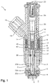
- FIGS. 2 to 7 Before with reference to FIGS. 2 to 7 several embodiments an anchor of an inventive Fuel injection valve will be described in more detail, should for a better understanding of the invention, first with reference to Fig. 1 is an already known fuel injection valve briefly explained with respect to its essential components become.
- the fuel injection valve 1 is in the form of a Injector for fuel injection systems of mixture-compression, spark-ignited internal combustion engines executed.
- the fuel injection valve 1 is suitable in particular for injecting fuel into a suction pipe 7 of an internal combustion engine.
- the closer in the following described measures to reduce the hydraulic Anchor damping are also suitable for direct in one Combustion chamber injecting high-pressure injection valves.
- the fuel injection valve 1 comprises a core 25, which is encapsulated with a plastic sheath 16.
- a valve needle 3 is connected to a valve closing body 4 in Compound which is connected to a valve seat body on the fifth arranged valve seat surface 6 to a sealing seat interacts.
- the core 25 forms an inner pole 11 of a magnetic flux circuit.
- a solenoid 8 is in the Plastic casing 16 encapsulated and on one Coil carrier 10 wound, which rests on the core 25. Of the Core 25 and serving as an outer pole nozzle body 2 are separated by a gap 12 and supported on a non-magnetic connection member 13 from.
- the Solenoid 8 is connected via an electrical line 14 of a via a plug contact 15 can be supplied electrical Electricity excited.
- the magnetic flux circuit is by a z. B. bow-shaped reflux body 17 is closed.
- a return spring 18 is supported, which in the present design of the Fuel injector 1 biased by a sleeve 19 becomes.
- the valve needle 3 is via a weld 20th positively connected to an armature 21.
- the fuel is passed through a central fuel supply 23 supplied via a filter 24.
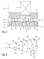
- Fig. 2 shows in an excerpt axial Sectional view of a first embodiment of the inventive design of the Fuel injector 1. It will be in the enlarged Showing only those components that are related are essential to the invention.
- the Design of the other components can with a known fuel injection valve 1, z. B. with the in Fig. 1 illustrated fuel injector 1, be identical. Already described elements are with matching Numeral provided so that a repeating Description is unnecessary.
- the armature 21 has two edge zones 31a, 31b in FIG. which by mutually inclined surfaces 32nd distinguished.
- the edge zones 31a, 31b there are two recesses 34 formed, each by two inwardly inclined Distinguish areas 32.
- the depressions 34 are available axial channels 35 in connection, parallel to the Longitudinal axis 30 of the armature 21 extend and the armature 21st penetrate.
- a recess 36 on a magnetic pole surface 44 of a magnetic body 43 which is annular and has a working gap 37 between the armature stopper surface 42 and the magnetic pole surface 44 enlarged locally.
- the recess 36 can be up to extend to the solenoid 8.
- the magnetic body 43 can also another solenoid 8 from the fuel be provided separating component.
- the magnetic coil 8 moves the armature 21 in the direction of the magnetic body 43 and displaces the existing in the working gap 37 Fuel. This is on the inclined surfaces 32 in the Channels 35 and to the inner edge 47 and the outer edge 46th displaced and can flow off via the armature 21.
- the Distribution of the fuel in the channels 35 and in the Outside and inside of the armature 21 is a faster Outflow of the liquid in the working gap 37, which the opening operation of the fuel injection valve. 1 does not bother.
- FIG. 3 shows, in an excerpted plan view, the armature 21 of the embodiment in Fig. 2 of the invention Embodiment of the fuel injection valve 1.
- Recessed concentric vertices 39 are in the Recesses 34. At regular intervals are in the recesses 34 channels 35, which are parallel to the longitudinal axis 30 of the armature 21 pierce the armature 21. It is also the diameter of the channels 35 to make variable, so that in each of the recesses 34 differently dimensioned Channels 35 corresponding to the increasing diameter Catchment area are attached.
- channels 35 affects that Flow behavior of the fuel considerably.
- Fig. 3 are therefore in the outer edge 46 of the armature 21st closer recess 34 channels 35 with larger Diameter, in the deeper recess 34th Channels 35 shown with a smaller diameter.
- a particularly advantageous arrangement of the channels 35 is present if they lie in the radial direction on a line.
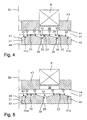
- Fig. 4 shows in a partial axial Sectional view of a second embodiment of a inventive design of the Fuel injection valve 1.
- the recesses 34 are here not two adjoining inclined surfaces 32.
- the two recesses 34 each have an inclined Surface 32 and a parallel to the longitudinal axis 30 of the armature 21st extending surface 40 on.
- the channels 35 and the in Area of the magnetic coil 8 located annular recess 36 of the magnetic body 43 are as in the first Embodiment designed in Fig. 2.
- the sawtooth Design of the recesses 34 is a particularly simple producible embodiment of the armature 21st
- Fig. 5 shows in an excerpt axial Sectional view of a third embodiment of a inventive design of the Fuel injection valve 1.
- the embodiment described here is a simplified variant of the embodiment in Fig. 2nd
- the anchor stop surface 42 also has two edge zones here 31a, 31b, which by two each inclined to each other Surfaces 32 are limited.
- In the only one intermediate recess 34 are channels 35th
- Fig. 6 shows in a partial axial Sectional view of a fourth embodiment of a inventive design of the Fuel injection valve 1.
- Fig. 5 Compared to the embodiment variant in Fig. 5 is distinguished the shape described in Fig. 6 by lowering a of the raised vertices 33. This results in a further reduction of the effective Anchor stop surface 38, whereby the armature 21 only at one of the vertices 33 and the adhesion of the anchor 21 on the magnetic body 43 is further reduced.
- the lowering of the one raised vertex 33 also causes there an enlargement of the working gap 37, which is favorable the flow behavior of existing in the working gap 37 Fuel effects.
- Fig. 7 shows in a plan view of the anchor stop surface 42 a fifth embodiment of an inventive Embodiment of the fuel injection valve 1.
- the invention is not limited to that shown Embodiment limited and also in a variety other designs of fuel injectors realizable.
- the invention also in Dive anchors 21 are used.
Abstract
Description
Die Erfindung geht aus von einem Brennstoffeinspritzventil nach der Gattung des Hauptanspruchs.The invention is based on a fuel injection valve according to the preamble of the main claim.
Aus der DE 35 35 438 A1 ist bereits ein elektromagnetisch
betätigbares Brennstoffeinspritzventil bekannt, welches in
einem Gehäuse eine einen ferromagnetischen Kern
umschließende Magnetspule aufweist. Zwischen einem fest mit
dem Gehäuse verbundenen Ventilsitzträger und der Stirnseite
des Gehäuses ist ein Flachanker angeordnet. Der Flachanker
wirkt über zwei Arbeitsluftspalte mit Gehäuse und Kern
zusammen und wird mittels einer ein Ventilschließteil
umgreifenden, gehäusefest eingespannten Führungsmembran
radial geführt. Die Verbindung zwischen dem Flachanker und
dem Ventilschließteil wird über einen das Ventilschließteil
umfassenden Ring hergestellt, welcher mit dem Flachanker
verschweißt ist. Das Ventilschließteil wird über eine
Schraubenfeder mit Schließdruck beaufschlagt.
Brennstoffkanäle sowie die Geometrie des Flachankers,
insbesondere die Absenkung der den Brennstoffkanälen
benachbarten Bereiche, erlauben ein Umströmen des Ankers
durch den Brennstoff.From
Nachteilig an dem aus der DE 35 35 438 A1 bekannten
Brennstoffeinspritzventil ist die hohe Kavitationsneigung
durch die großen vom Brennstoff durchflossenen Hohlräume, in
denen Strömungen und Verwirbelungen entstehen. Die
Verdrängung des Brennstoffs beim Anziehen des Ankers
geschieht aufgrund des hohen Strömungswiderstands verzögert
und hat damit nachteilige Auswirkungen auf die Öffnungszeit
des Brennstoffeinspritzventils. Die Kavitation wird zudem
durch die Lage der Durchströmöffnungen, welche nicht am
Scheitelpunkt, sondern in der Flanke des Flachankers
angebracht sind, verstärkt.A disadvantage of the known from
In der DE 31 43 849 C2 wird ein ähnlich geformter Flachanker in einem Brennstoffeinspritzventil verwendet. Hier sind zwar die Durchströmöffnungen an den Scheitelpunkten des Flachankers angebracht; die hydrodynamischen Eigenschaften sind jedoch durch den nach wie vor hochgezogenen Rand des Ankers, welcher parallel zu der Ankeranschlagfläche ausgerichtet ist und eine Verdrängung des Brennstoffs in die Randbereiche des Ankers unmöglich macht, nur unwesentlich verbessert.In DE 31 43 849 C2 is a similarly shaped flat armature used in a fuel injection valve. Here are indeed the flow openings at the vertices of the Flat anchor attached; the hydrodynamic properties are, however, by the still elevated edge of the Anchor, which is parallel to the anchor stop surface is aligned and a displacement of the fuel in the Edge areas of the anchor makes impossible, only insignificantly improved.
Aus der EP 0 683 862 B1 ist ein elektromagnetisch betätigbares Brennstoffeinspritzventil bekannt, dessen Anker dadurch gekennzeichnet ist, daß die dem Innenpol zugewandte Ankeranschlagfläche geringfügig keilförmig ausgebildet ist, um die hydraulische Dämpfung beim Öffnen des Brennstoffeinspritzventils und die hydraulische Adhäsionskraft nach Abschaltung des die Magnetspule erregenden Stromes zu minimieren oder ganz zu unterbinden. Ferner ist durch geeignete Maßnahmen wie Bedampfen und Nitrieren die Anschlagfläche des Ankers verschleißfest gestaltet, so daß die Anschlagfläche während der gesamten Lebensdauer des Brennstoffeinspritzventils die gleiche Größe aufweist und die Funktionsweise des Brennstoffeinspritzventils nicht beeinträchtigt wird.From EP 0 683 862 B1 is an electromagnetic operable fuel injector known whose armature characterized in that facing the inner pole Anchor stop surface is slightly wedge-shaped, around the hydraulic damping when opening the Fuel injector and the hydraulic Adhesive force after switching off the solenoid coil To minimize or completely suppress exciting current. Furthermore, by appropriate measures such as steaming and Nitrate the stop surface of the armature wear-resistant designed so that the stop surface during the entire Life of the fuel injector the same size and the operation of the Fuel injector is not affected.
Nachteilig an dem aus der EP 0 683 862 B1 bekannten Brennstoffeinspritzventil ist vor allem die trotz der optimierten Ankeranschlagfläche nach wie vor vorhandene hydraulische Dämpfungskraft im Arbeitsspalt beim Anziehen des Ankers. Wird ein Erregerstrom an die Magnetspule angelegt, bewegt sich der Anker in Richtung des Innenpols und verdrängt dabei den zwischen dem Innenpol und dem Anker vorhandenen Brennstoff. Aufgrund von Reibungs- und Trägheitseffekten kommt es dabei zum Aufbau eines lokalen Druckfeldes, welches auf der Ankeranschlagfläche eine hydraulische Kraft erzeugt, die gegen die Bewegungsrichtung des Ankers wirkt. Dadurch verlängern sich die Öffnungs- und Zumeßzeiten des Brennstoffeinspritzventils.A disadvantage of the known from EP 0 683 862 B1 Fuel injection valve is mainly the despite of optimized anchor stop surface still existing hydraulic damping force in the working gap when tightening of the anchor. Is an excitation current to the solenoid applied, the armature moves in the direction of the inner pole and displaces the between the inner pole and the anchor existing fuel. Due to friction and Inertia effects are the result of building a local Pressure field, which on the anchor stop surface a generates hydraulic force, which is against the direction of movement the anchor acts. This lengthens the opening and Metering times of the fuel injection valve.
Das erfindungsgemäße Brennstoffeinspritzventil mit den Merkmalen des Hauptanspruchs hat demgegenüber den Vorteil, daß durch geeignete geometrische Gestaltung des Ankers die hydraulische Dämpfungskraft erheblich herabgesetzt wird und damit das Brennstoffeinspritzventil schneller geöffnet werden kann, was in präziseren Zumeßzeiten und -mengen resultiert.The fuel injection valve according to the invention with the Features of the main claim has the advantage over that by suitable geometric design of the anchor the hydraulic damping force is significantly reduced and so that the fuel injector opens faster can be, resulting in more precise metering times and quantities results.
Eine günstige Geometrie der Ankeranschlagfläche wird durch das gegensinnige Abschrägen der Randbereiche der Ankeranschlagfläche erreicht. Der Anker besitzt zwei ringförmige Randzonen, wobei die innere Randzone nach innen zum Innenradius geneigt ist, während die äußere der Randzonen nach außen zum Außenradius geneigt ist. Die Ankeranschlagfläche ist somit von geneigten Flächen begrenzt. Der Neigungswinkel der Randflächen beeinflußt das Strömungsverhalten des im Arbeitsspalt befindlichen Brennstoffs. Die Ankeranschlagfläche wird durch die geometrische Gestaltung verkleinert, wodurch die Verschleißfläche geringer ist.A favorable geometry of the anchor stop surface is through the opposing bevels of the edge regions of Anchor stop surface reached. The anchor has two annular edge zones, wherein the inner edge zone inwards is inclined to the inner radius, while the outer of Edge zones is inclined outwards to the outer radius. The Anchor stop surface is thus of inclined surfaces limited. The angle of inclination of the edge surfaces influences this Flow behavior of the work gap located Fuel. The anchor stop surface is through the reduced geometric design, causing the Wear surface is less.
Durch die in den Unteransprüchen aufgeführten Maßnahmen sind vorteilhafte Weiterbildungen und Verbesserungen des im Hauptanspruch angegebenen Brennstoffeinspritzventils möglich.By the measures listed in the dependent claims are advantageous developments and improvements in the Main claim specified fuel injector possible.
Von Vorteil ist insbesondere das Anbringen von axialen Kanälen im Anker, wodurch der im Arbeitsspalt vorhandene Brennstoff die Möglichkeit erhält, bei Betätigung des Ankers durch diesen hindurch abzuströmen. Die Kanäle werden vorteilhafterweise in Vertiefungen angeordnet, wodurch sich das Strömungsverhalten weiter verbessert, da der Brennstoff ohne Verzögerung durch den Anker entweichen kann.Of particular advantage is the attachment of axial Channels in the anchor, causing the existing in the working gap Fuel receives the opportunity, upon actuation of the anchor to flow through it. The channels will be advantageously arranged in depressions, whereby the flow behavior further improved as the fuel can escape through the anchor without delay.
Derselbe Effekt kann auch durch Aussparungen, die am Außenrand des Ankers in regelmäßigen Abständen angebracht sind, erzielt werden. Der Brennstoff wird in diesem Fall bedingt durch die nach außen abgeschrägte Form der Ankeranschlagfläche an den äußeren Rand einer den Anker aufnehmenden zentralen Ausnehmung des Brennstoffeinspritzventils verdrängt und kann durch die Aussparungen im Anker abströmen.The same effect can also be achieved by recesses on the Outside edge of the anchor attached at regular intervals are achieved. The fuel will be in this case due to the outwardly tapered shape of the Anchor stop surface to the outer edge of the anchor receiving central recess of the Fuel injector displaced and can by the Cut out recesses in the anchor.
Die Vertiefungen können durch eine schräge und eine senkrechte Fläche begrenzt werden. Eine weitere mögliche Ausgestaltungsvariante sieht eine unterschiedliche Höhe für die durch die geneigten Flächen gebildeten, erhabenen ringförmigen Scheitelpunkte vor, so daß nur noch eine minimale Fläche als Ankeranschlagfläche dient.The depressions can be made by an oblique and a vertical area be limited. Another possible Design variant sees a different height for the raised ones formed by the inclined surfaces ring-shaped vertices, so that only one minimal area serves as anchor stop surface.
Eine ringförmige Aussparung an der Magnetfläche im Bereich der Magnetspule bewirkt durch eine lokale Vergrößerung des Arbeitsspaltes eine positive Beeinflussung der hydraulischen Dämpfung.An annular recess on the magnetic surface in the area the magnet coil causes by a local enlargement of the Working gap a positive influence on the hydraulic Damping.
Ausführungsbeispiele der Erfindung sind in der Zeichnung vereinfacht dargestellt und in der nachfolgenden Beschreibung näher erläutert. Es zeigen:
- Fig. 1
- einen axialen Schnitt durch ein Brennstoffeinspritzventil gemäß dem Stand der Technik,
- Fig. 2
- einen schematisierten, vergrößerten Schnitt durch ein erstes Ausführungsbeispiel eines Ankers eines erfindungsgemäßen Brennstoffeinspritzventils,
- Fig. 3
- eine Draufsicht auf die Ankeranschlagfläche des Ankers in Fig. 2,
- Fig. 4
- einen schematisierten, vergrößerten Schnitt durch ein zweites Ausführungsbeispiel eines Ankers eines erfindungsgemäßen Brennstoffeinspritzventils,
- Fig. 5
- einen schematisierten, vergrößerten Schnitt durch ein drittes Ausführungsbeispiel eines Ankers eines erfindungsgemäßen Brennstoffeinspritzventils,
- Fig. 6
- einen schematisierten, vergrößerten Schnitt durch ein viertes Ausführungsbeispiel eines Ankers eines erfindungsgemäßen Brennstoffeinspritzventils und
- Fig. 7
- eine Draufsicht auf die Ankeranschlagfläche eines fünften Ausführungsbeispiels eines Ankers eines erfindungsgemäßen Brennstoffeinspritzventils.
- Fig. 1
- an axial section through a fuel injection valve according to the prior art,
- Fig. 2
- a schematic, enlarged section through a first embodiment of an armature of a fuel injection valve according to the invention,
- Fig. 3
- a plan view of the anchor stop surface of the armature in Fig. 2,
- Fig. 4
- a schematic, enlarged section through a second embodiment of an armature of a fuel injection valve according to the invention,
- Fig. 5
- a schematic, enlarged section through a third embodiment of an armature of a fuel injection valve according to the invention,
- Fig. 6
- a schematic enlarged sectional view of a fourth embodiment of an armature of a fuel injection valve according to the invention and
- Fig. 7
- a plan view of the armature stop surface of a fifth embodiment of an armature of a fuel injection valve according to the invention.
Bevor anhand der Fig. 2 bis 7 mehrere Ausführungsbeispiele eines Ankers eines erfindungsgemäßen Brennstoffeinspritzventils näher beschrieben werden, soll zum besseren Verständnis der Erfindung zunächst anhand von Fig. 1 ein bereits bekanntes Brennstoffeinspritzventil bezüglich seiner wesentlichen Bauteile kurz erläutert werden.Before with reference to FIGS. 2 to 7 several embodiments an anchor of an inventive Fuel injection valve will be described in more detail, should for a better understanding of the invention, first with reference to Fig. 1 is an already known fuel injection valve briefly explained with respect to its essential components become.
Das Brennstoffeinspritzventil 1 ist in der Form eines
Einspritzventils für Brennstoffeinspritzanlagen von
gemischverdichtenden, fremdgezündeten Brennkraftmaschinen
ausgeführt. Das Brennstoffeinspritzventil 1 eignet sich
insbesondere zum Einspritzen von Brennstoff in ein Saugrohr
7 einer Brennkraftmaschine. Die im folgenden näher
beschriebenen Maßnahmen zur Reduzierung der hydraulischen
Ankerdämpfung eignen sich jedoch ebenso bei direkt in einen
Brennraum einspritzenden Hochdruckeinspritzventilen.The
Das Brennstoffeinspritzventil 1 umfaßt einen Kern 25,
welcher mit einer Kunststoffummantelung 16 umspritzt ist.
Eine Ventilnadel 3 steht mit einem Ventilschließkörper 4 in
Verbindung, der mit einer an einem Ventilsitzkörper 5
angeordneten Ventilsitzfläche 6 zu einem Dichtsitz
zusammenwirkt. Bei dem Brennstoffeinspritzventil 1 handelt
es sich im Ausführungsbeispiel um ein nach innen öffnendes
Brennstoffeinspritzventil 1, welches in ein Saugrohr 7
einspritzt. Der Kern 25 bildet einen Innenpol 11 eines
magnetischen Flußkreises. Eine Magnetspule 8 ist in der
Kunststoffummantelung 16 gekapselt und auf einen
Spulenträger 10 gewickelt, welcher am Kern 25 anliegt. Der
Kern 25 und ein als Außenpol dienender Düsenkörper 2 sind
durch einen Spalt 12 voneinander getrennt und stützen sich
auf einem nichtmagnetischen Verbindungsbauteil 13 ab. Die
Magnetspule 8 wird über eine elektrische Leitung 14 von
einem über einen Steckkontakt 15 zuführbaren elektrischen
Strom erregt. Der magnetische Flußkreis wird durch einen
z. B. bügelförmigen Rückflußkörper 17 geschlossen.The
An der Ventilnadel 3 stützt sich eine Rückstellfeder 18 ab,
welche in der vorliegenden Bauform des
Brennstoffeinspritzventils 1 durch eine Hülse 19 vorgespannt
wird. Die Ventilnadel 3 ist über eine Schweißnaht 20
kraftschlüssig mit einem Anker 21 verbunden.At the
Der Brennstoff wird durch eine zentrale Brennstoffzufuhr 23
über einen Filter 24 zugeführt.The fuel is passed through a
Im Ruhezustand des Brennstoffeinspritzventils 1 wird der
Anker 21 von der Rückstellfeder 18 entgegen seiner
Hubrichtung so beaufschlagt, daß der Ventilschließkörper 4
am Ventilsitz 6 in dichtender Anlage gehalten wird. Bei
Erregung der Magnetspule 8 baut diese ein Magnetfeld auf,
welches den Anker 21 entgegen der Federkraft der
Rückstellfeder 18 in Hubrichtung bewegt. Der Anker 21 nimmt
die Ventilnadel 3 ebenfalls in Hubrichtung mit. Der mit der
Ventilnadel 3 in Verbindung stehende Ventilschließkörper 4
hebt von der Ventilsitzfläche 6 ab und Brennstoff wird über
Radialbohrungen 22a in der Ventilnadel 3, eine Aussparung
22b im Ventilsitzkörper 5 und Abflachungen 22c am
Ventilschließkörper 4 zum Dichtsitz geführt.In the idle state of the
Wird der Spulenstrom abgeschaltet, fällt der Anker 21 nach
genügendem Abbau des Magnetfeldes durch den Druck der
Rückstellfeder 18 vom Innenpol 11 ab, wodurch sich die mit
dem Anker 21 in Verbindung stehende Ventilnadel 3 entgegen
der Hubrichtung bewegt, der Ventilschließkörper 4 auf der
Ventilsitzfläche 6 aufsetzt und das
Brennstoffeinspritzventil 1 geschlossen wird.If the coil current is turned off, the
Fig. 2 zeigt in einer auszugsweisen axialen
Schnittdarstellung ein erstes Ausführungsbeispiel der
erfindungsgemäßen Ausgestaltung des
Brennstoffeinspritzventils 1. Es werden in der vergrößerten
Darstellung nur diejenigen Komponenten gezeigt, die in Bezug
auf die Erfindung von wesentlicher Bedeutung sind. Die
Ausgestaltung der übrigen Komponenten kann mit einem
bekannten Brennstoffeinspritzventil 1, z. B. mit dem in Fig.
1 dargestellten Brennstoffeinspritzventil 1, identisch sein.
Bereits beschriebene Elemente sind mit übereinstimmenden
Bezugszeichen versehen, so daß sich eine wiederholende
Beschreibung erübrigt.Fig. 2 shows in an excerpt axial
Sectional view of a first embodiment of the
inventive design of the
Der bereits in Fig. 1 beschriebene Anker 21, welcher in Fig.
1 als sog. Tauchanker 21 ausgeführt ist, liegt in Fig. 2 bis
7 in Form eines Flachankers 21 vor. In den Fig. 2 bis 6 ist
jeweils nur eine Hälfte des Ankers 21 rechts der
symmetrischen Längsachse 30 dargestellt. The
Der Anker 21 weist in Fig. 2 zwei Randzonen 31a, 31b auf,
die sich durch gegeneinander geneigte Flächen 32
auszeichnen. Dabei ist die Fläche 32 der inneren Randzone
31a durch einen eine zentrale Ausnehmung 48 begrenzenden
Innenrand 47 des Flachankers 21 begrenzt und zum Innenrand
47 geneigt, während die Fläche 32 der äußeren Randzone 31b
durch einen Außenrand 46 begrenzt ist und zum Außenrand 46
geneigt ist.The
Zwischen den Randzonen 31a, 31b sind zwei Vertiefungen 34
ausgebildet, die sich jeweils durch zwei nach innen geneigte
Flächen 32 auszeichnen. Die Vertiefungen 34 stehen mit
axialen Kanälen 35 in Verbindung, die parallel zur
Längsachse 30 des Ankers 21 verlaufen und den Anker 21
durchdringen.Between the
Im Bereich der Magnetspule 8 befindet sich eine Ausnehmung
36 an einer Magnetpolfläche 44 eines Magnetkörpers 43,
welche ringförmig ausgebildet ist und einen Arbeitsspalt 37
zwischen der Ankeranschlagfläche 42 und der Magnetpolfläche
44 lokal vergrößert. Die Ausnehmung 36 kann sich dabei bis
zur Magnetspule 8 erstrecken. Anstelle des Magnetkörpers 43
kann auch ein anderes die Magnetspule 8 vom Brennstoff
abtrennendes Bauteil vorgesehen sein.In the region of the
Wird der Magnetspule 8 ein Erregerstrom zugeführt, bewegt
sich der Anker 21 in Richtung auf den Magnetkörper 43 und
verdrängt dabei den im Arbeitsspalt 37 vorhandenen
Brennstoff. Dieser wird über die geneigten Flächen 32 in die
Kanäle 35 bzw. an den Innenrand 47 und den Außenrand 46
verdrängt und kann über den Anker 21 abfließen. Durch die
Verteilung des Brennstoffs in die Kanäle 35 und in den
Außen- bzw. Innenbereich des Ankers 21 entsteht ein rascher
Abfluß der im Arbeitsspalt 37 befindlichen Flüssigkeit,
welche den Öffnungsvorgang des Brennstoffeinspritzventils 1
nicht stört. If the
Fig. 3 zeigt in einer auszugsweisen Draufsicht den Anker 21
des Ausführungsbeispiels in Fig. 2 der erfindungsgemäßen
Ausgestaltung des Brennstoffeinspritzventils 1.FIG. 3 shows, in an excerpted plan view, the
Erhabene konzentrische Scheitelpunkte 33, an welchen die
geneigten Flächen 32 aneinandergrenzen, bilden drei
ringförmige Restankeranschlagflächen 38. Der Anker 21
schlägt somit am Ende des Öffnungsvorganges nicht mehr mit
der ganzen Ankeranschlagfläche 42 am Magnetkörper 43 an,
sondern mit den durch die Scheitelpunkte 33 gebildeten
ringförmigen Restankeranschlagflächen 38. Dadurch wird der
Schließvorgang beschleunigt, da die kleinere
Restankeranschlagfläche 38 auch eine geringere hydraulische
Adhäsionskraft erfährt und sich der Anker 21 somit leichter
vom Magnetkörper 43 löst.Lofty
Vertiefte konzentrische Scheitelpunkte 39 liegen in den
Vertiefungen 34. In regelmäßigen Abständen befinden sich in
den Vertiefungen 34 Kanäle 35, die parallel zur Längsachse
30 des Ankers 21 den Anker 21 durchstoßen. Dabei ist auch
der Durchmesser der Kanäle 35 variabel zu gestalten, so daß
in jeder der Vertiefungen 34 unterschiedlich dimensionierte
Kanäle 35 entsprechend des mit dem Durchmesser zunehmenden
Einzugsbereichs angebracht sind.Recessed
Die Anzahl und die Abmessung der Kanäle 35 beeinflußt das
Strömungsverhalten des Brennstoffs beträchtlich. In Fig. 3
sind deshalb in der dem Außenrand 46 des Ankers 21
näherliegenden Vertiefung 34 Kanäle 35 mit größerem
Durchmesser, in der weiter innen liegenden Vertiefung 34
Kanäle 35 mit geringerem Durchmesser dargestellt. Eine
besonders vorteilhafte Anordnung der Kanäle 35 liegt vor,
wenn diese in radialer Richtung auf einer Linie liegen.The number and size of
Fig. 4 zeigt in einer auszugsweisen axialen
Schnittdarstellung ein zweites Ausführungsbeispiel einer
erfindungsgemäßen Ausgestaltung des
Brennstoffeinspritzventils 1. Fig. 4 shows in a partial axial
Sectional view of a second embodiment of a
inventive design of the
Im Gegensatz zu Fig. 2 bestehen die Vertiefungen 34 hier
nicht aus zwei aneinandergrenzenden, geneigten Flächen 32.
Die beiden Vertiefungen 34 weisen jeweils eine geneigte
Fläche 32 und eine parallel zur Längsachse 30 des Ankers 21
verlaufende Fläche 40 auf. Die Kanäle 35 sowie die im
Bereich der Magnetspule 8 befindliche ringförmige Ausnehmung
36 des Magnetkörpers 43 sind wie im ersten
Ausführungsbeispiel in Fig. 2 gestaltet. Die sägezahnförmige
Gestaltung der Vertiefungen 34 ist eine besonders einfach
herstellbare Ausführungsform des Ankers 21.In contrast to Fig. 2, the
Fig. 5 zeigt in einer auszugsweisen axialen
Schnittdarstellung ein drittes Ausführungsbeispiel einer
erfindungsgemäßen Ausgestaltung des
Brennstoffeinspritzventils 1.Fig. 5 shows in an excerpt axial
Sectional view of a third embodiment of a
inventive design of the
Das hier beschriebene Ausführungsbeispiel ist eine
vereinfachte Variante des Ausführungsbeispiels in Fig. 2.
Die Ankeranschlagfläche 42 weist auch hier zwei Randzonen
31a, 31b auf, welche durch je zwei gegeneinander geneigte
Flächen 32 begrenzt sind. In der einzigen
dazwischenliegenden Vertiefung 34 befinden sich Kanäle 35.The embodiment described here is a
simplified variant of the embodiment in Fig. 2nd
The anchor stop
Fig. 6 zeigt in einer auszugsweisen axialen
Schnittdarstellung ein viertes Ausführungsbeispiel einer
erfindungsgemäßen Ausgestaltung des
Brennstoffeinspritzventils 1.Fig. 6 shows in a partial axial
Sectional view of a fourth embodiment of a
inventive design of the
Gegenüber der Ausgestaltungsvariante in Fig. 5 zeichnet sich
die in Fig. 6 beschriebene Form durch eine Absenkung eines
der erhabenen Scheitelpunkte 33 aus. Dies resultiert in
einer weiteren Verkleinerung der effektiven
Ankeranschlagfläche 38, wodurch der Anker 21 nur an einem
der Scheitelpunkte 33 anschlägt und die Adhäsion des Ankers
21 am Magnetkörper 43 weiter reduziert wird. Die Absenkung
des einen erhabenen Scheitelpunkts 33 bewirkt dort zudem
eine Vergrößerung des Arbeitsspalts 37, was sich günstig auf
das Strömungsverhalten des im Arbeitsspalt 37 vorhandenen
Brennstoffes auswirkt. Compared to the embodiment variant in Fig. 5 is distinguished
the shape described in Fig. 6 by lowering a
of the raised
Fig. 7 zeigt in einer Draufsicht auf die Ankeranschlagfläche
42 ein fünftes Ausführungsbeispiel einer erfindungsgemäßen
Ausgestaltung des Brennstoffeinspritzventils 1.Fig. 7 shows in a plan view of the anchor stop surface
42 a fifth embodiment of an inventive
Embodiment of the
Zur besseren Verteilung und Abführung des im Arbeitsspalt 37
vorhandenen Brennstoffs sind am Außenrand 46 des Ankers 21
Aussparungen 41 vorgesehen. Dies führt ebenfalls zur
Verkleinerung der effektiven Ankeranschlagfläche 38 sowie zu
einer zügigen randseitigen Verdrängung des Brennstoffes über
die geneigte Fläche 32 der Randzone 31b.For better distribution and removal of the working gap in the 37th
existing fuel are at the
Die Erfindung ist nicht auf das dargestellte Ausführungsbeispiel beschränkt und auch bei einer Vielzahl anderer Bauweisen von Brennstoffeinspritzventilen realisierbar. Insbesondere kann die Erfindung auch bei Tauchankern 21 zum Einsatz kommen.The invention is not limited to that shown Embodiment limited and also in a variety other designs of fuel injectors realizable. In particular, the invention also in Dive anchors 21 are used.
Claims (8)
- Fuel injection valve (1) for fuel injection systems of internal combustion engines, with a magnet coil (8), with an armature (21) acted upon in a closing direction by a return spring (18), and with a valve-closing body (4) which is connected non-positively to the armature (21) and, together with a valve-seat surface (6), forms a sealing seat, the armature (21) butting with an armature abutment surface (42) against a magnetic pole face (44), and the armature (21) having an outer edge (46) and an inner edge (47) delimiting a central recess (48), and the armature abutment surface (42) having an inner annular first edge zone (31a), which is contiguous to the inner edge (47) and which is inclined inwards with respect to a plane perpendicular to a longitudinal axis (30) of the armature (21), and an outer annular second edge zone (31b) which is contiguous to the outer edge (46) and which is inclined outwards with respect to a plane perpendicular to a longitudinal axis (30) of the armature (21), characterized in that at least one depression (34) is formed between the inclined annular edge zones (31a, 31b).
- Fuel injection valve according to Claim 1, characterized in that each depression (34) is delimited by two inclined faces (32) which are inclined in opposite directions with respect to the plane perpendicular to the longitudinal axis (30) of the armature (21).
- Fuel injection valve according to Claim 1, characterized in that each depression (34) between the inclined edge zones (31a, 31b) is delimited by a first inclined face (32), which is inclined with respect to the plane perpendicular to the longitudinal axis (30) of the armature (21), and a second face (40), which runs parallel to the longitudinal axis (30) of the armature (21).
- Fuel injection valve according to Claim 2 or 3, characterized in that the armature abutment surface (42) has raised vertex points (33), at which the distance between the armature abutment surface (42) and the magnetic pole face (44) is minimum, and recessed vertex points (39), at which the distance between the armature abutment surface (42) and the magnetic pole face (44) is maximum.
- Fuel injection valve according to Claim 4, characterized in that axial ducts (35) which pass through the armature (21) commence at the recessed vertex points (39).
- Fuel injection valve according to Claim 5, characterized in that the distance between the armature abutment surface (42) and the magnetic pole face (44) and the raised vertex points (33) is different.
- Fuel injection valve according to one of the preceding claims, characterized in that the armature (21) has at least one clearance (41) at its outer edge (46).
- Fuel injection valve according to one of the preceding claims, characterized in that the magnetic pole face (44) has an annular recess (36) in the region of the magnet coil (8).
Applications Claiming Priority (3)
| Application Number | Priority Date | Filing Date | Title |
|---|---|---|---|
| DE19960605 | 1999-12-16 | ||
| DE19960605A DE19960605A1 (en) | 1999-12-16 | 1999-12-16 | Fuel injector |
| PCT/DE2000/004450 WO2001044652A1 (en) | 1999-12-16 | 2000-12-14 | Fuel injection valve |
Publications (2)
| Publication Number | Publication Date |
|---|---|
| EP1155231A1 EP1155231A1 (en) | 2001-11-21 |
| EP1155231B1 true EP1155231B1 (en) | 2005-10-26 |
Family
ID=7932826
Family Applications (1)
| Application Number | Title | Priority Date | Filing Date |
|---|---|---|---|
| EP00993232A Expired - Lifetime EP1155231B1 (en) | 1999-12-16 | 2000-12-14 | Fuel injection valve |
Country Status (9)
| Country | Link |
|---|---|
| US (1) | US6758419B2 (en) |
| EP (1) | EP1155231B1 (en) |
| JP (1) | JP2003517141A (en) |
| CN (1) | CN1186526C (en) |
| BR (1) | BR0008230A (en) |
| CZ (1) | CZ295771B6 (en) |
| DE (2) | DE19960605A1 (en) |
| ES (1) | ES2249327T3 (en) |
| WO (1) | WO2001044652A1 (en) |
Families Citing this family (12)
| Publication number | Priority date | Publication date | Assignee | Title |
|---|---|---|---|---|
| DE10039083A1 (en) * | 2000-08-10 | 2002-02-21 | Bosch Gmbh Robert | Fuel injector |
| DE10148592A1 (en) * | 2001-10-02 | 2003-04-10 | Bosch Gmbh Robert | Fuel injector |
| DE10256662A1 (en) | 2002-12-04 | 2004-06-17 | Robert Bosch Gmbh | Fuel injector |
| DE10325442A1 (en) * | 2003-06-05 | 2004-12-23 | Robert Bosch Gmbh | Solenoid valve with reduced switching noise |
| US7156368B2 (en) * | 2004-04-14 | 2007-01-02 | Cummins Inc. | Solenoid actuated flow controller valve |
| US7637442B2 (en) * | 2005-03-09 | 2009-12-29 | Keihin Corporation | Fuel injection valve |
| DE102008042593A1 (en) * | 2008-10-02 | 2010-04-08 | Robert Bosch Gmbh | Fuel injector and surface treatment methods |
| US8316826B2 (en) * | 2009-01-15 | 2012-11-27 | Caterpillar Inc. | Reducing variations in close coupled post injections in a fuel injector and fuel system using same |
| JP5689395B2 (en) * | 2011-09-28 | 2015-03-25 | ナブテスコ株式会社 | solenoid valve |
| DE102014221586A1 (en) * | 2014-10-23 | 2016-04-28 | Robert Bosch Gmbh | fuel injector |
| DE102017222951A1 (en) * | 2017-12-15 | 2019-06-19 | Robert Bosch Gmbh | Electromagnetically actuated inlet valve and high-pressure fuel pump |
| CN114635818A (en) * | 2022-03-09 | 2022-06-17 | 哈尔滨工程大学 | High-speed electromagnetic valve for realizing stable injection of common rail fuel injector by utilizing flexible hydraulic damping |
Citations (1)
| Publication number | Priority date | Publication date | Assignee | Title |
|---|---|---|---|---|
| EP0683862B1 (en) * | 1993-12-09 | 1998-06-10 | Robert Bosch Gmbh | Electromagnetic valve |
Family Cites Families (14)
| Publication number | Priority date | Publication date | Assignee | Title |
|---|---|---|---|---|
| DE3143849A1 (en) | 1981-11-05 | 1983-05-11 | Robert Bosch Gmbh, 7000 Stuttgart | ELECTROMAGNETICALLY ACTUABLE VALVE, ESPECIALLY FUEL INJECTION VALVE |
| DE3207918A1 (en) * | 1982-03-05 | 1983-09-15 | Robert Bosch Gmbh, 7000 Stuttgart | ELECTROMAGNETICALLY ACTUABLE VALVE |
| DE3305039A1 (en) * | 1983-02-14 | 1984-08-16 | Robert Bosch Gmbh, 7000 Stuttgart | ELECTROMAGNETICALLY ACTUABLE VALVE |
| GB8519251D0 (en) * | 1985-07-31 | 1985-09-04 | Lucas Ind Plc | Fuel injector |
| DE3535438A1 (en) | 1985-10-04 | 1987-04-09 | Bosch Gmbh Robert | Electromagnetically operable valve |
| DE3704543A1 (en) | 1987-02-13 | 1988-08-25 | Vdo Schindling | Fuel injection valve |
| DE3714693A1 (en) | 1987-05-02 | 1988-11-10 | Bosch Gmbh Robert | ELECTROMAGNETICALLY ACTUABLE VALVE |
| DE3727342A1 (en) * | 1987-08-17 | 1989-03-02 | Bosch Gmbh Robert | ELECTROMAGNETICALLY ACTUABLE FUEL INJECTION VALVE |
| GB8728628D0 (en) | 1987-12-08 | 1988-01-13 | Lucas Ind Plc | Fuel injection valve |
| US5372313A (en) * | 1993-02-16 | 1994-12-13 | Siemens Automotive L.P. | Fuel injector |
| US5417373A (en) * | 1994-02-10 | 1995-05-23 | Siemens Automotive L.P. | Electromagnet for valves |
| DE19503821A1 (en) * | 1995-02-06 | 1996-08-08 | Bosch Gmbh Robert | Electromagnetically actuated valve |
| DE19712590A1 (en) * | 1997-03-26 | 1998-10-01 | Bosch Gmbh Robert | Electromagnetically actuated valve |
| DE19905721A1 (en) * | 1998-02-24 | 1999-08-26 | Hoerbiger Ventilwerke Gmbh | Electromagnetically actuated gas valve for use as a fuel injection valve in a gas engine |
-
1999
- 1999-12-16 DE DE19960605A patent/DE19960605A1/en not_active Withdrawn
-
2000
- 2000-12-14 DE DE50011450T patent/DE50011450D1/en not_active Expired - Fee Related
- 2000-12-14 CN CNB008038643A patent/CN1186526C/en not_active Expired - Fee Related
- 2000-12-14 US US09/913,657 patent/US6758419B2/en not_active Expired - Fee Related
- 2000-12-14 EP EP00993232A patent/EP1155231B1/en not_active Expired - Lifetime
- 2000-12-14 CZ CZ20012970A patent/CZ295771B6/en not_active IP Right Cessation
- 2000-12-14 WO PCT/DE2000/004450 patent/WO2001044652A1/en active IP Right Grant
- 2000-12-14 BR BR0008230-9A patent/BR0008230A/en active Search and Examination
- 2000-12-14 JP JP2001545716A patent/JP2003517141A/en active Pending
- 2000-12-14 ES ES00993232T patent/ES2249327T3/en not_active Expired - Lifetime
Patent Citations (1)
| Publication number | Priority date | Publication date | Assignee | Title |
|---|---|---|---|---|
| EP0683862B1 (en) * | 1993-12-09 | 1998-06-10 | Robert Bosch Gmbh | Electromagnetic valve |
Also Published As
| Publication number | Publication date |
|---|---|
| WO2001044652A1 (en) | 2001-06-21 |
| EP1155231A1 (en) | 2001-11-21 |
| BR0008230A (en) | 2001-10-30 |
| CZ295771B6 (en) | 2005-11-16 |
| CN1186526C (en) | 2005-01-26 |
| DE19960605A1 (en) | 2001-07-19 |
| ES2249327T3 (en) | 2006-04-01 |
| DE50011450D1 (en) | 2005-12-01 |
| CN1340133A (en) | 2002-03-13 |
| US20020125343A1 (en) | 2002-09-12 |
| JP2003517141A (en) | 2003-05-20 |
| US6758419B2 (en) | 2004-07-06 |
Similar Documents
| Publication | Publication Date | Title |
|---|---|---|
| DE4018256A1 (en) | ELECTROMAGNETICALLY ACTUABLE FUEL INJECTION VALVE | |
| EP1309793B1 (en) | Fuel injection valve | |
| DE102006052817A1 (en) | Fuel injection valve for e.g. direct injection of fuel into combustion chamber of internal combustion engine, has valve seat body and closing body provided with rigidity-reducing element that is designed as recess i.e. circulating groove | |
| EP1155231B1 (en) | Fuel injection valve | |
| EP1381771B1 (en) | Fuel injection valve | |
| DE10118162B9 (en) | Fuel injector | |
| EP1576278A1 (en) | Fuel injection valve | |
| WO2011082916A1 (en) | Fuel injection valve | |
| EP1262655B1 (en) | Fuel injection valve | |
| DE102010064097A1 (en) | Electromagnetically actuatable valve e.g. fuel injection valve of internal combustion engine, has movable valve needle with lower stopper comprising top stop face with elevations and depressions on which armature rests | |
| DE10049033B4 (en) | Fuel injector | |
| DE10050751B4 (en) | Fuel injector | |
| DE10256667A1 (en) | Fuel injector | |
| EP1481157B1 (en) | Fuel injection valve | |
| DE10049034B4 (en) | Fuel injector | |
| DE10051016A1 (en) | Fuel injection valve, for an IC motor, has a guide collar around the armature with interruption gaps to prevent the armature tilting or shifting to the side in the opening of the outer pole | |
| DE10063261B4 (en) | Fuel injector | |
| DE102004048603A1 (en) | Valve for supplying in particular gaseous media | |
| EP1309790B1 (en) | Fuel injection valve | |
| DE102021212790A1 (en) | Electromagnetically actuable valve and method of manufacture | |
| WO2003081022A1 (en) | Fuel injection valve | |
| DE10354465B4 (en) | Fuel injector | |
| EP1300583B1 (en) | Fuel injection valve | |
| DE102021212791A1 (en) | Electromagnetically actuable valve and method of manufacture | |
| DE10143500A1 (en) | Fuel injection valve for fuel injection system for IC engine, has guide collar with flat deviating from circular outer contour of armature so that at least one aperture is formed between collar and guiding counter surface |
Legal Events
| Date | Code | Title | Description |
|---|---|---|---|
| PUAI | Public reference made under article 153(3) epc to a published international application that has entered the european phase |
Free format text: ORIGINAL CODE: 0009012 |
|
| AK | Designated contracting states |
Kind code of ref document: A1 Designated state(s): AT BE CH CY DE DK ES FI FR GB GR IE IT LI LU MC NL PT SE TR |
|
| 17P | Request for examination filed |
Effective date: 20011221 |
|
| RBV | Designated contracting states (corrected) |
Designated state(s): DE ES FR GB |
|
| 17Q | First examination report despatched |
Effective date: 20041119 |
|
| GRAP | Despatch of communication of intention to grant a patent |
Free format text: ORIGINAL CODE: EPIDOSNIGR1 |
|
| GRAS | Grant fee paid |
Free format text: ORIGINAL CODE: EPIDOSNIGR3 |
|
| GRAA | (expected) grant |
Free format text: ORIGINAL CODE: 0009210 |
|
| AK | Designated contracting states |
Kind code of ref document: B1 Designated state(s): DE ES FR GB |
|
| REG | Reference to a national code |
Ref country code: GB Ref legal event code: FG4D Free format text: NOT ENGLISH |
|
| REF | Corresponds to: |
Ref document number: 50011450 Country of ref document: DE Date of ref document: 20051201 Kind code of ref document: P |
|
| PGFP | Annual fee paid to national office [announced via postgrant information from national office to epo] |
Ref country code: FR Payment date: 20051220 Year of fee payment: 6 |
|
| PGFP | Annual fee paid to national office [announced via postgrant information from national office to epo] |
Ref country code: ES Payment date: 20051227 Year of fee payment: 6 |
|
| GBT | Gb: translation of ep patent filed (gb section 77(6)(a)/1977) |
Effective date: 20060201 |
|
| REG | Reference to a national code |
Ref country code: ES Ref legal event code: FG2A Ref document number: 2249327 Country of ref document: ES Kind code of ref document: T3 |
|
| ET | Fr: translation filed | ||
| PLBE | No opposition filed within time limit |
Free format text: ORIGINAL CODE: 0009261 |
|
| STAA | Information on the status of an ep patent application or granted ep patent |
Free format text: STATUS: NO OPPOSITION FILED WITHIN TIME LIMIT |
|
| 26N | No opposition filed |
Effective date: 20060727 |
|
| GBPC | Gb: european patent ceased through non-payment of renewal fee |
Effective date: 20061214 |
|
| REG | Reference to a national code |
Ref country code: FR Ref legal event code: ST Effective date: 20070831 |
|
| PG25 | Lapsed in a contracting state [announced via postgrant information from national office to epo] |
Ref country code: GB Free format text: LAPSE BECAUSE OF NON-PAYMENT OF DUE FEES Effective date: 20061214 |
|
| REG | Reference to a national code |
Ref country code: ES Ref legal event code: FD2A Effective date: 20061215 |
|
| PG25 | Lapsed in a contracting state [announced via postgrant information from national office to epo] |
Ref country code: FR Free format text: LAPSE BECAUSE OF NON-PAYMENT OF DUE FEES Effective date: 20070102 Ref country code: ES Free format text: LAPSE BECAUSE OF NON-PAYMENT OF DUE FEES Effective date: 20061215 |
|
| PGFP | Annual fee paid to national office [announced via postgrant information from national office to epo] |
Ref country code: GB Payment date: 20051220 Year of fee payment: 6 |
|
| PGFP | Annual fee paid to national office [announced via postgrant information from national office to epo] |
Ref country code: DE Payment date: 20090224 Year of fee payment: 9 |
|
| PG25 | Lapsed in a contracting state [announced via postgrant information from national office to epo] |
Ref country code: DE Free format text: LAPSE BECAUSE OF NON-PAYMENT OF DUE FEES Effective date: 20100701 |