EP1154641A1 - Method and apparatus for digital signal processing - Google Patents
Method and apparatus for digital signal processing Download PDFInfo
- Publication number
- EP1154641A1 EP1154641A1 EP00976315A EP00976315A EP1154641A1 EP 1154641 A1 EP1154641 A1 EP 1154641A1 EP 00976315 A EP00976315 A EP 00976315A EP 00976315 A EP00976315 A EP 00976315A EP 1154641 A1 EP1154641 A1 EP 1154641A1
- Authority
- EP
- European Patent Office
- Prior art keywords
- signal processing
- digital signal
- block
- bus
- set forth
- Prior art date
- Legal status (The legal status is an assumption and is not a legal conclusion. Google has not performed a legal analysis and makes no representation as to the accuracy of the status listed.)
- Withdrawn
Links
Images





Classifications
-
- H—ELECTRICITY
- H04—ELECTRIC COMMUNICATION TECHNIQUE
- H04N—PICTORIAL COMMUNICATION, e.g. TELEVISION
- H04N21/00—Selective content distribution, e.g. interactive television or video on demand [VOD]
- H04N21/40—Client devices specifically adapted for the reception of or interaction with content, e.g. set-top-box [STB]; Operations thereof
-
- H—ELECTRICITY
- H04—ELECTRIC COMMUNICATION TECHNIQUE
- H04N—PICTORIAL COMMUNICATION, e.g. TELEVISION
- H04N21/00—Selective content distribution, e.g. interactive television or video on demand [VOD]
- H04N21/40—Client devices specifically adapted for the reception of or interaction with content, e.g. set-top-box [STB]; Operations thereof
- H04N21/41—Structure of client; Structure of client peripherals
- H04N21/426—Internal components of the client ; Characteristics thereof
-
- G—PHYSICS
- G06—COMPUTING OR CALCULATING; COUNTING
- G06F—ELECTRIC DIGITAL DATA PROCESSING
- G06F13/00—Interconnection of, or transfer of information or other signals between, memories, input/output devices or central processing units
- G06F13/38—Information transfer, e.g. on bus
-
- H—ELECTRICITY
- H04—ELECTRIC COMMUNICATION TECHNIQUE
- H04N—PICTORIAL COMMUNICATION, e.g. TELEVISION
- H04N21/00—Selective content distribution, e.g. interactive television or video on demand [VOD]
- H04N21/40—Client devices specifically adapted for the reception of or interaction with content, e.g. set-top-box [STB]; Operations thereof
- H04N21/43—Processing of content or additional data, e.g. demultiplexing additional data from a digital video stream; Elementary client operations, e.g. monitoring of home network or synchronising decoder's clock; Client middleware
- H04N21/442—Monitoring of processes or resources, e.g. detecting the failure of a recording device, monitoring the downstream bandwidth, the number of times a movie has been viewed, the storage space available from the internal hard disk
- H04N21/4424—Monitoring of the internal components or processes of the client device, e.g. CPU or memory load, processing speed, timer, counter or percentage of the hard disk space used
-
- H—ELECTRICITY
- H04—ELECTRIC COMMUNICATION TECHNIQUE
- H04N—PICTORIAL COMMUNICATION, e.g. TELEVISION
- H04N21/00—Selective content distribution, e.g. interactive television or video on demand [VOD]
- H04N21/80—Generation or processing of content or additional data by content creator independently of the distribution process; Content per se
- H04N21/81—Monomedia components thereof
- H04N21/8166—Monomedia components thereof involving executable data, e.g. software
- H04N21/818—OS software
-
- H—ELECTRICITY
- H04—ELECTRIC COMMUNICATION TECHNIQUE
- H04N—PICTORIAL COMMUNICATION, e.g. TELEVISION
- H04N7/00—Television systems
- H04N7/16—Analogue secrecy systems; Analogue subscription systems
- H04N7/162—Authorising the user terminal, e.g. by paying; Registering the use of a subscription channel, e.g. billing
- H04N7/163—Authorising the user terminal, e.g. by paying; Registering the use of a subscription channel, e.g. billing by receiver means only
-
- H—ELECTRICITY
- H04—ELECTRIC COMMUNICATION TECHNIQUE
- H04N—PICTORIAL COMMUNICATION, e.g. TELEVISION
- H04N21/00—Selective content distribution, e.g. interactive television or video on demand [VOD]
- H04N21/40—Client devices specifically adapted for the reception of or interaction with content, e.g. set-top-box [STB]; Operations thereof
- H04N21/43—Processing of content or additional data, e.g. demultiplexing additional data from a digital video stream; Elementary client operations, e.g. monitoring of home network or synchronising decoder's clock; Client middleware
- H04N21/431—Generation of visual interfaces for content selection or interaction; Content or additional data rendering
- H04N21/4312—Generation of visual interfaces for content selection or interaction; Content or additional data rendering involving specific graphical features, e.g. screen layout, special fonts or colors, blinking icons, highlights or animations
- H04N21/4316—Generation of visual interfaces for content selection or interaction; Content or additional data rendering involving specific graphical features, e.g. screen layout, special fonts or colors, blinking icons, highlights or animations for displaying supplemental content in a region of the screen, e.g. an advertisement in a separate window
-
- H—ELECTRICITY
- H04—ELECTRIC COMMUNICATION TECHNIQUE
- H04N—PICTORIAL COMMUNICATION, e.g. TELEVISION
- H04N21/00—Selective content distribution, e.g. interactive television or video on demand [VOD]
- H04N21/40—Client devices specifically adapted for the reception of or interaction with content, e.g. set-top-box [STB]; Operations thereof
- H04N21/47—End-user applications
Definitions
- the present invention relates to a digital signal processing apparatus, a system thereof, and an extension function providing method that are suitable for a digital broadcast receiving device that receives a satellite digital broadcast or a ground wave digital broadcast, in particular, to those that allow the receiving device to be effectively designed, easily design-changed, and easily applied for an added service and an improved function.
- Analog television broadcasts are becoming changed to digital television broadcasts. So far, digital satellite broadcast services using CS (Communication Satellites) have been started. In addition, digital satellite broadcast services using BS (Broadcasting Satellites) are being prepared. Moreover, digital television broadcasts using ground waves are scheduled to be started.
- CS Common Satellites
- BS Broadcasting Satellites
- digital television broadcasts since the frequency efficiency is improved, more channels can be assigned than analog television broadcasts.
- HDTV (High Definition Television) broadcasts can be easily performed.
- various services such as bidirectional service, data delivery service, and video-on-demand that are not available in conventional analog television broadcasts can be accomplished.
- a television receiver that receives such a digital television broadcast is conventionally structured as shown in Fig. 1.
- a received signal is supplied from an input terminal 101 to a tuner circuit 102.
- a signal of 12 GHz band is received by a parabola antenna (not shown).
- the received signal is converted into a signal of 1 GHz band by a low noise converter disposed in the parabola antenna.
- the converted signal is supplied to the tuner circuit 102.
- the tuner circuit 102 selects a carrier frequency signal of a desired channel from the received signal and performs a demodulating process and an error correcting process for the selected signal.
- the tuner circuit 102 decodes the selected signal to a transport stream composed of video packets and audio packets.
- An output of the tuner circuit 102 is supplied to a demultiplexer 103.
- the demultiplexer 103 separates the transport stream into video packets and audio packets.
- the video packets are supplied to a video decoder 104.
- the audio packets are supplied to an audio decoder 105.
- the video decoder 104 performs a decompressing process for the video packets corresponding to for example the MPEG 2 (Moving Picture Experts Group) system so as to decode the video packets to video data.
- the audio decoder 105 performs a decompressing process for the audio packets corresponding to the MPEG system so as to decode the audio packets to audio data.
- the video data decoded by the video decoder 104 is supplied to a graphics processing circuit 106.
- the graphics processing circuit 106 performs a picture process.
- An output of the graphics processing circuit 106 is output from an output terminal 107.
- An output of the audio decoder 105 is output from an output terminal 108.
- the tuner circuit 102, the demultiplexer 103, the video decoder 104, the audio decoder 105, and the graphics processing circuit 106 are controlled by an MPU (Micro Processor Unit) 111.
- a bus 111 extends from the MPU 111.
- the tuner circuit 102, the demultiplexer 103, the video decoder 104, the audio decoder 105, and the graphics processing circuit 106 are connected to the bus 110.
- a modem 112 and for example an IEEE (Institute of Electrical and Electronics Engineers) 1394 interface 113 are connected to the bus 110.
- the modem 112 is used to perform a charging process.
- the IEEE 1394 interface 113 exchanges a stream with an external device.
- the entire receiver is controlled by an MPU.
- the MPU centrally controls each portion of hardware using commands thereof in consideration of precise timing levels thereof.
- functions necessary for a television receiver may be structured as blocks and connected through a common bus.
- a standardized controlling bus has been proposed.
- the conventional controlling bus is used to exchange control data among the MPU and the individual blocks.
- streams of video data and audio data are not sent to the bus.
- the conventional bus that exchanges only control data cannot be used.
- a bus for control data and another bus for streams of video data and audio data may be separately disposed, streams and control data should be synchronized. To do that, a timing signal is required. When the timing signal is sent, the buses depend on hardware. Thus, a general-purpose designing method cannot be used.
- an object of the present invention is to provide a digital signal processing apparatus and a receiving method that allow the developing efficiency to be improved and the design to be easily changed.
- Another object of the present invention is to provide a digital signal processing apparatus and a method that allow a new service and a change of a broadcasting system to be easily handled.
- the present invention is a digital signal processing apparatus, comprising:
- the present invention is a digital signal processing method, comprising the steps of:
- Elements necessary for a digital television receiver are structured as blocks and connected through a general-purpose bus.
- various types of digital television broadcasts that differ in carrier waves, modulating systems, and compressing systems can be handled.
- the developing efficiency is improved.
- the service can be easily handled.
- Fig. 1 is a block diagram showing an example of a conventional receiving device for a digital television broadcast
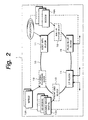
- Fig. 2 is a block diagram for explaining the basic structure of the present invention
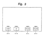
- Fig. 3 is a schematic diagram for explaining generations of commands and a screen display
- Fig. 4 is a schematic diagram for explaining a command sent from a host processor
- Fig. 5 is a schematic diagram for explaining a command sent from the host processor
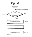
- Fig. 6 is a flow chart for explaining the case that a driver is installed
- Fig. 7 is a block diagram showing an example of a television receiver according to the present invention
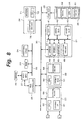
- Fig. 8 is a block diagram showing an example of an encrypting process performed in the television receiver according to the present invention
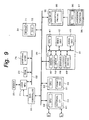
- FIG. 9 is a block diagram showing another example of the encrypting process performed in the television receiver according to the present invention.
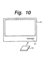
- Fig. 10 is a perspective view for explaining the television receiver according to the present invention.
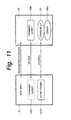
- Fig. 11 is a block diagram for explaining the case that an extension plug-in card is attached to the television receiver according to the present invention;
- Fig. 12 is a schematic diagram for explaining generations of commands and a display screen in the case that a new device is attached;
- Fig. 13 is a flow chart for explaining the case that the extension plug-in card is attached to the television receiver according to the present invention; and
- Fig. 14 is a flow chart for explaining the case that the extension plug-in card is attached to the television receiver according to the present invention.
- a digital television receiver is structured in such a manner that elements necessary for the digital television receiver are structured as blocks and connected through a bus.
- Fig. 2 shows the basic structure of a digital television receiver of which elements necessary for the receiver are structured as blocks and connected through a bus.
- a digital television receiver 1 is structured in such a manner that blocks 11, 12, 13, 14, 15, and 16 necessary for the digital television receiver 1 are connected to a bus 10.
- the blocks 11, 12, 13, 14, 15, and 16 necessary for the digital television receiver are a host MPU block 11, an AV signal processing block 12, a front end block 13, an interface block 14, a plug-in interface block 15, and a built-in feature block 16 that are connected to the bus 10.
- the host MPU block 11 controls the entire receiver.
- the AV signal processing block 12 performs a decompressing process for a video stream and an audio stream and a graphic process.
- the front end block 13 selects a carrier wave signal of a desired channel from a received television broadcast and performs a demodulating process, an error correcting process, and so forth for the selected signal so as to decode the video stream and the audio stream.
- the interface block 14 is an interface such as the IEEE 1394 interface for connecting the receiver with an external device.
- the plug-in interface block 15 is an interface for connecting the receiver with hardware for an extension function.
- the built-in feature block 16 accomplishes a required built-in function.
- Chronological successive streams of video data and audio data, commands, and data are transferred to the bus 10.
- the commands are high level layer commands that are not on real time basis and that do not depend on hardware structure, not low level layer commands for directly controlling hardware.
- a command "Receive a frequency of X channel.” is issued to the front end block 13.
- Those commands are also general-purpose script type commands such as "Enlarge (or reduce) the screen.” or "Draw a circle.” that are issued to the AV signal processing block 12.
- a script of which up - down keys 201A and 201B and enlarge - reduce keys 201C and 201D are displayed and commands CMD1 to CMD4 corresponding to the indications 201A to 201E are embedded is created with hypertext.
- a screen shown in Fig. 3 is displayed on a screen of a browser.
- commands CMD1 to CMD4 corresponding thereto are generated.
- the commands are sent to the relevant blocks 11 to 16.
- the block performs a process corresponding to the command.
- JAVA or the like can be used.
- the physical structure of the bus 10 is standardized.
- the blocks 11, 12, 13, 14, 15, and 16 are designed so that they comply with the standardized bus.
- Basic blocks such as the host MPU block 11, the interface block 14, and the plug-in interface block 15 may be disposed on a mother board.
- the other blocks 12, 13, and 16 may be disposed on a daughter board.
- the blocks 12, 13, and 16 may be connected to the standardized bus.
- the individual blocks 11, 12, 13, 14, 15, and 16 may be structured as integrated circuits or modules.
- the receiver is divided into the host MPU block 11, the AV signal processing block 12, the front end block 13, the interface block 14, the plug-in interface block 15, and the built-in feature block 16.
- the dividing method is not limited to such an example.
- each block is disposed on a board, one block is not always composed of one board.
- two or more functional blocks may be disposed on one board.
- the host MPU block 11 and the interface block 14 may be disposed on one board.
- one block may be composed of a plurality of boards.
- Each of the block 11, 12, 13, 14, 15, and 16 interprets a command received through the bus 10, executes a process corresponding to the command, and processes a stream and data received through the bus 10.
- each of the blocks 12, 13, 14, 15, and 16 Since a command that does not largely depend on hardware is received through the bus 10, each of the blocks 12, 13, 14, 15, and 16 has a CPU (Central Processing Unit) in many cases so as to interpret the received command and process it.
- the CPU of each of the blocks 12, 13, 14, 15, and 16 interprets a received command and executes a process corresponding to the command.
- Each of the blocks 12, 13, 14, 15, and 16 has a driver that operates hardware corresponding to the received command. A portion that largely depends on hardware completes a process in the block thereof.
- the host MPU block 11 side has a high level interface HIF for a process with a high level command that is a general purpose command and that does not depend on hardware.
- each of the blocks 12, 13, 14, and 15 side has a driver DRV that interprets a high level command and performs a process that more depends on hardware and a low level interface LIF that directly controls the hardware.
- the host MPU block 11 side sends a high level command through the high level interface HIF and transfers it to each block through the bus 10.
- the driver DRV of each block interprets a high level command. In that case, portions that depend on hardware are handled by the driver DRV of each of the blocks 12, 13, 14, and 15.
- the host MPU block 11 side may have a driver DRV.
- a new driver DRV should be installed or the existing driver DRV should be changed.
- High speed streams such as streams of video data and audio data and data that is not on real time basis such as commands and data are transferred to the bus 10.
- a bus that can transfer different types of data may have two bands that are a band for a high speed stream such as video data and audio data and a band for data that is not on real time basis such as commands.
- data may be assigned priority in such a manner that streams of video data and audio data are assigned high priority so that the streams of video data and audio data are transmitted at high speed.
- a command that is transmitted to the bus 10 is for example a script type command that is not on real time basis unlike a timing control command.
- the data amount of a command that is sent can be remarkably suppressed. Consequently, the same bus 10 can send both commands and streams of video data and audio data.
- the digital television receiver is structured in such a manner that the individual blocks 11, 12, 13, 14, 15, and 16 are connected through the bus 10 and commands, streams, and data are exchanged through the bus 10.
- the digital television receiver can easily handle various types of television broadcasts. Consequently, the developing environment of the receiver is remarkably improved.
- the carrier frequency, modulating system, error correcting system, transport stream structure, and so forth of the conventional digital satellite broadcasts are different from those of ground wave digital broadcasts
- the AV signal processing block 12 and the front end block 13 for the ground wave digital broadcasts can be developed.
- an AV signal processing block 12A for ground wave digital broadcasts and a front end block 13A for ground wave digital broadcasts are developed.
- the television receiver can handle the ground wave digital broadcasts that will be newly started.
- receivers for digital television broadcasts through satellites in European countries and receivers for digital television broadcasts of US CATV stations can be easily developed without need to newly design those receivers from the beginning.
- a television receiver has a modem that is used for a charging process and that is connected to a management company through a telephone line.
- a modem 16A is disposed as the built-in feature 16.
- a device necessary for receiving such a broadcast service can be easily mounted as the built-in feature block 16.
- a music data downloading service a video-on-demand service, and other services are expected.
- hardware may be added. In that case, the hardware is added as a device attached to the plug-in interface block 15.
- a driver thereof may be required.
- the driver may be stored in a memory of the block or a memory of the device attached to the plug-in interface block 15.
- the driver may be automatically installed. In that case, the operability is improved.
- a service center when a block is replaced or when a device is attached to the plug-in interface block 15, a service center may be called and a relevant driver may be downloaded therefrom.
- step S101 it is determined whether a block has been replaced or a new device has been attached to the plug-in interface block 15 (at step S101).
- the replaced device or the new device is recognized (at step S102).
- the service center is called by a telephone (at step S103).
- software of the driver corresponding to the recognized device is transmitted through the telephone line.
- the software of the driver is downloaded (at step S104).
- software of the driver may be downloaded with a digital satellite broadcast signal or a digital ground wave broadcast signal.
- digital television broadcasts are performed through various transmission mediums such as a satellite, a ground wave, a CATV network, and a television line.
- Carrier waves, modulating systems, and compressing systems used for digital television broadcasts vary depending on transmission mediums, countries and areas, broadcasting companies, and so forth.
- various services such as HDTV broadcast, data delivery service, and video-on-demand service are expected.
- receivers for digital television broadcasts corresponding to various transmission mediums, areas, services, and so forth should be developed.
- blocks that accomplish individual functions of a television receiver are connected to a standardized bus. Streams of video data and audio data and commands are exchanged through the standardized bus. In that case, the developing efficiency of television receivers is improved. In addition, various types of television receivers can easily handle services that will be newly started.
- Fig. 7 shows an example of the real structure of such a television receiver.
- an internal bus 22 extends from a host MPU 21.
- a ROM (Read Only Memory) 23 is connected to the bus 22.
- An additional logic 24 is connected to the internal bus 22 so as to extend a function.
- the ROM 23 stores an application program for operating the entire television receiver.
- An SDRAM 25 is connected to the host CPU 21.
- the SDRAM 25 stores user's personal information and various types of setting information.
- the host CPU 21 is connected to a bus 30 through a bus controller 26.
- the bus 30 is used to transmit streams of video data and audio data that are chronologically successive data and commands and data.
- the commands are high layer commands that do not depend on hardware and that are not on real time basis.
- An AV signal processing block 31, a front end block 32, an external interface block 33, and a built-in feature block 34 are connected to the bus 30.
- the bus 30 has a plug-in interface 35.
- An extension plug-in card 36 can be attached to the plug-in interface 35.
- a portion composed of the host MPU 21 may be disposed on a mother board.
- Each of the blocks 31, 32, 33, and 34 may be disposed on a daughter board.
- the shapes and terminal positions of the mother board and the daughter board may be pre-designated so that the daughter boards of the blocks 31, 32, 33, and 34 may be attached and detached to / from the mother board of the host MPU 21.
- the blocks 31, 32, 33, and 34 may be structured as blocks or integrated circuits.
- Data transferred among the host MPU 21, the blocks 31, 32, 33, and 34, and the extension plug-in card 36 through the bus 30 is managed by the bus controller 26.
- data may be directly transferred among the blocks 31, 32, 33, and 34 and the extension plug-in card 36 not through the host MPU 21 by the DMA (Direct Memory Access) control.
- DMA Direct Memory Access
- Data can be transferred from one-block to one block.
- data can be transferred from one block to a plurality of blocks.
- data can be broadcast.
- the broadcast transferring operation can be used when a transport stream received from the front end block 32 is transmitted to the AV signal processing block 31 and the external interface block 33 at the same time so that while a picture is being reproduced, the transport stream can be transmitted to a device connected to the external interface block 33.
- the AV signal processing block 31 extracts video packets and audio packets from the transport stream and decompresses the video packets and audio packets to original video data and audio data.
- the AV signal processing block 31 can perform a picture process for the decoded video data.
- the AV signal processing block 31 has a CPU 41, a video decoder 42, an audio decoder 43, a demultiplexer 44, a graphics processing circuit 45, and a bridge circuit 46.
- the CPU 41, the video decoder 42, the audio decoder 43, the demultiplexer 44, the graphics processing circuit 45, and the bridge circuit 46 are connected to an in-chip bus 47.
- the front end block 32 selects a desired carrier wave signal from the received signal, demodulates the selected carrier wave signal, performs an error correcting process for the demodulated signal, and outputs a transport stream.
- the front end block 32 has a front end pack 51 and a CPU 52.
- the front end pack 51 has a mixer circuit, a local oscillating circuit, an intermediate frequency amplifying circuit, a demodulating circuit, an error correcting circuit, and so forth that convert the received signal into an intermediate frequency signal.
- the interface block 33 provides an interface with an external device corresponding to for example the IEEE 1394 standard.
- the external interface block 33 has an interface 61 corresponding to for example the IEEE 1394 standard and a CPU 62.
- the built-in feature block 34 is used to provide an addition circuit necessary for receiving a digital broadcast.
- received data is transferred through a telephone line so as to perform a charging process.
- a modem is disposed in the built-in feature block 34.
- the built-in feature block 34 has a circuit 71 that accomplishes an additional function (in this case, a modem) and a CPU 72.
- the plug-in interface 35 provides an extension function for receiving a new service.
- the extension plug-in card 36 is attached to the plug-in interface 35.
- the extension plug-in card 36 has an extension function 81 and a CPU 82.
- the extension function 81 is composed of software and hardware that accomplish an extension function.
- the structure shown in Fig. 7 composes a television receiver 20 that receives for example a digital CS broadcast.
- the front end block 32 that performs the QPSK demodulating process, the Viterbi decoding process, and the Reed-Solomon code error correcting process is used.
- the AV signal processing block 31 that decompresses video packets of transport streams compressed corresponding to the MPEG 2 system and audio packets compressed corresponding to the MPEG system is used.
- a signal of 12 GHz band is used.
- a received signal of 12 GHz band transmitted from a satellite is received by a parabola antenna (not shown).
- the received signal is converted into a signal of around 1 GHz by a low noise converter disposed in the parabola antenna and sent to the front end block 32.
- the front end block 32 selects a carrier wave signal of a desired channel from the received signal.
- the front end block 32 performs the QPSK demodulating process, the Viterbi decoding process, and the Reed-Solomon code error correcting process for the signal so as to decode the received signal to the transport stream.
- the received channel is selected corresponding to a command sent from the host MPU 21 through the bus 30.
- the host MPU 21 sends a high layer command such as "Receive a frequency of X channel.” through the bus 30.
- the command is sent from the bus 30 to the CPU 52 of the front end block 32.
- the CPU 52 interprets the command and generates a control signal for designating the received frequency to a desired carrier wave frequency corresponding to the command.
- the CPU 52 generates a control signal of the PLL that composes the local oscillator. As a result, the frequency of the received channel is designated.
- the front end block 32 outputs a transport stream of packets of video data compressed corresponding to the MPEG 2 system and packets of audio data compressed corresponding to the MPEG system.
- the transport stream is sent to the AV signal processing block 31 through the bus 30. Thereafter, the transport stream is sent from the AV signal processing block 31 to the demultiplexer 44 through the bridge 46 and the in-chip bus 47.
- the demultiplexer 44 separates the transport stream into video packets and audio packets.
- the video packets are sent to the video decoder 42.
- the audio packets are sent to the audio decoder 43.
- the video decoder 42 performs the decompressing process for the video data compressed corresponding to the MPEG 2 system so as to decode the video data.
- the audio decoder 43 performs the decompressing process for the audio data compressed corresponding to the MPEG audio system so as to decode the audio data.
- the video data decoded by the video decoder 42 is sent to the graphics processing circuit 45 through the in-chip bus 47.
- the graphics processing circuit 45 performs the picture process for the video data.
- the picture process performed by the graphics processing circuit 45 depends on a command received from the host MPU 21 through the bus 30.
- a high layer command for example "Reduce (or enlarge) the screen.” is sent from the host MPU 21 through the bus 30.
- the command is sent from the bus 30 to the CPU 41 through the bridge circuit 46.
- the CPU 41 interprets the command and generates a control signal for reducing / enlarging the screen in the designated size corresponding to the command. In reality, the CPU 41 sends a timing signal for reducing or enlarging the screen and a command for directly controlling hardware to the graphics processing circuit 45 corresponding to the received high layer command.
- the individual functions necessary for structuring the television receiver 20 are connected as the blocks 31, 32, 33, 34, and 35 to the bus 30. Commands and streams are transferred through the bus 30.
- the bus 30 is standardized, the developing efficiency of a television receiver is improved.
- a television receiver corresponding to a change of a broadcasting system, a change of a service, or an addition of a service can be easily developed.
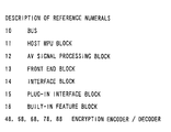
- encryption encoders / decoders 48, 58, 68, 78, and 88 are disposed in the blocks 31, 32, 33, 34, and 35, and the extension plug-in card 36 connected to the bus 30, respectively.
- the encryption encoders / decoders 48, 58, 68, 78, and 88 encode streams of video packets and audio packets transferred from the blocks 31, 32, 33, 34, and 35 through the bus 30. Since streams of video packets and audio packets transferred through the bus 30 are encrypted in such a manner, the contents can be protected.
- the encryption encoders / decoders 48, 58, 68, 78, and 88 are disposed in the blocks 31, 32, 33, and 34, and the extension plug-in card 36, respectively.
- the bus 30 extends from the plug-in interface 35 to the outside. When a device that copies data is connected to the plug-in interface 35 and contents are extracted from the bus 30, the risk of which the contents are leaked out becomes the highest.
- an encoding encoder / decoder 89 may be disposed in the plug-in interface 35 so that data of contents that flow on the bus 30 is not leaked out from the plug-in interface 35.
- the extension plug-in card 36 when the extension plug-in card 36 is attached to the external extension bridge 35, a new function can be added so that the receiver can handle a new service.
- a card attaching portion 91 is disposed on the front of the television receiver 20.
- the extension plug-in card 36 is attached to the card attaching portion 91.
- the extension plug-in card 36 is connected to the bus 30 through the plug-in interface 35.
- extension plug-in card 36 When the extension plug-in card 36 is connected to the bus 30 through the plug-in interface 35, a function corresponding to a new service can be extended.
- controlling software may be required.
- the controlling software may be provided as a record medium such as a magnetic disk or an optical disc.
- the user may install the software to the television receiver. However, in that case, the user should spend time for the installing operation.
- a script is stored in the memory of the extension plug-in card 36.
- the script is uploaded to the main memory of the host MPU 21.
- the extension plug-in card 36 has a command script CMD, a command interface CIF, and a driver DRV.
- the host MPU 21 recognizes that the extension plug-in card 36 has been attached.
- the command script CMD for causing the extension plug-in card 36 to operate is uploaded to the host CPU 21 side.
- the host MPU 21 side can generate a command for causing the extension plug-in card 36 that has been attached to operate.
- a script engine SENG of the host MPU 21 side When the extension plug-in card 36 is operated, a script engine SENG of the host MPU 21 side generates a command. The command is sent to the extension plug-in card 36 through the bus 30.
- the command interface CIF of the extension plug-in card 36 interprets the command.
- the driver DRV controls hardware corresponding to the received command.
- a script is described as hypertext that embeds CMD 11, CMD 12, CMD 13, CMD 14, and CMD 15 for rewind, stop, play, fast forward, and record commands corresponding to a rewind key 202A, a stop key 202B, a play key 202C, a fast forward key 202D, and a record key 202C, respectively.
- a screen as shown in Fig. 12 is displayed by a browser.
- the keys 202A to 202E are clicked, the embedded commands are generated.
- the operation of the device is controlled.
- Fig. 13 and Fig. 14 are flow charts showing such a process.
- the host MPU 21 determines that the extension plug-in card 36 has been attached (at step S2). Thereafter, the host MPU 21 determines whether or not the attached card is the extension plug-in card 36 (at step S3). When the determined result of the host MPU 21 represents that the attached card is not the extension plug-in card 36, the host MPU 21 outputs an alarm (at step S4).
- the command script CMD stored in the extension plug-in card 36 is uploaded (at step S5).
- the host MPU 21 recognizes a command for the attached extension plug-in card 36 and performs a process for the attached extension plug-in card 36.
- Fig. 14 after the command script has been uploaded, when the user performs an operation for the extension plug-in card 36 (at step S11), the script is checked (at step S12). Thereafter, it is determined whether or not the checked result is correct (at step S13). When the checked result is not correct, an alarm is output (at step S14). When the checked result is correct, the script engine SENG interprets the script (at step S15) and issues a command (at step S15). The extension plug-in device is operated corresponding to the command (at step S17).
- a receiver for a digital broadcast was described.
- the present invention can be also applied to other devices such as a digital VTR.
- elements necessary for a digital television receiver are structured as blocks and connected through a general-purpose bus. Streams of video data and audio data and commands are transferred to the bus.
- various types of digital television broadcasts that differ in carrier waves, modulating systems, and compressing systems can be handled. Consequently, the developing efficiency of a television receiver is improved.
- the service can be easily handled.
- the present invention is particularly suitable for accomplishing a television receiver that receives various types of digital broadcasts that differ in carrier waves, modulating systems, compressing systems, and so forth.
Landscapes
- Engineering & Computer Science (AREA)
- Multimedia (AREA)
- Signal Processing (AREA)
- General Engineering & Computer Science (AREA)
- Theoretical Computer Science (AREA)
- Software Systems (AREA)
- Computer Security & Cryptography (AREA)
- Computer Networks & Wireless Communication (AREA)
- Databases & Information Systems (AREA)
- Physics & Mathematics (AREA)
- General Physics & Mathematics (AREA)
- Stored Programmes (AREA)
- Two-Way Televisions, Distribution Of Moving Picture Or The Like (AREA)
- Compression Or Coding Systems Of Tv Signals (AREA)
- Small-Scale Networks (AREA)
- Television Systems (AREA)
Abstract
Elements necessary for a digital television
receiver are structured as a plurality of digital
signal processing blocks and a host operation
processing block. The blocks are connected through a
general-purpose bus. Command for controlling the
operations of the blocks and data of streams are
transferred through the bus. Thus, by replacing only
blocks, various types of digital television broadcasts
that differ in carrier waves, modulating systems, and
compressing systems can be handled. Consequently, the
developing efficiency of a television receiver is
improved. In addition, when a new service is started,
by adding hardware for the service, the service can be
easily handled.
Description
The present invention relates to a digital
signal processing apparatus, a system thereof, and an
extension function providing method that are suitable
for a digital broadcast receiving device that receives
a satellite digital broadcast or a ground wave digital
broadcast, in particular, to those that allow the
receiving device to be effectively designed, easily
design-changed, and easily applied for an added service
and an improved function.
Analog television broadcasts are becoming
changed to digital television broadcasts. So far,
digital satellite broadcast services using CS
(Communication Satellites) have been started. In
addition, digital satellite broadcast services using BS
(Broadcasting Satellites) are being prepared. Moreover,
digital television broadcasts using ground waves are
scheduled to be started.
In digital television broadcasts, since the
frequency efficiency is improved, more channels can be
assigned than analog television broadcasts. In
addition, HDTV (High Definition Television) broadcasts
can be easily performed. Moreover, in digital
television broadcasts, various services such as bidirectional
service, data delivery service, and video-on-demand
that are not available in conventional analog
television broadcasts can be accomplished.
A television receiver that receives such a
digital television broadcast is conventionally
structured as shown in Fig. 1.
In Fig. 1, a received signal is supplied from
an input terminal 101 to a tuner circuit 102. In the
case of a CS digital broadcast, a signal of 12 GHz band
is received by a parabola antenna (not shown). The
received signal is converted into a signal of 1 GHz
band by a low noise converter disposed in the parabola
antenna. The converted signal is supplied to the tuner
circuit 102. The tuner circuit 102 selects a carrier
frequency signal of a desired channel from the received
signal and performs a demodulating process and an error
correcting process for the selected signal. As a
result, the tuner circuit 102 decodes the selected
signal to a transport stream composed of video packets
and audio packets.
An output of the tuner circuit 102 is
supplied to a demultiplexer 103. The demultiplexer 103
separates the transport stream into video packets and
audio packets.
The video packets are supplied to a video
decoder 104. The audio packets are supplied to an
audio decoder 105. The video decoder 104 performs a
decompressing process for the video packets
corresponding to for example the MPEG 2 (Moving Picture
Experts Group) system so as to decode the video packets
to video data. In addition, the audio decoder 105
performs a decompressing process for the audio packets
corresponding to the MPEG system so as to decode the
audio packets to audio data.
The video data decoded by the video decoder
104 is supplied to a graphics processing circuit 106.
The graphics processing circuit 106 performs a picture
process. An output of the graphics processing circuit
106 is output from an output terminal 107. An output
of the audio decoder 105 is output from an output
terminal 108.
The tuner circuit 102, the demultiplexer 103,
the video decoder 104, the audio decoder 105, and the
graphics processing circuit 106 are controlled by an
MPU (Micro Processor Unit) 111. A bus 111 extends from
the MPU 111. The tuner circuit 102, the demultiplexer
103, the video decoder 104, the audio decoder 105, and
the graphics processing circuit 106 are connected to
the bus 110.
In addition, a modem 112 and for example an
IEEE (Institute of Electrical and Electronics
Engineers) 1394 interface 113 are connected to the bus
110. The modem 112 is used to perform a charging
process. The IEEE 1394 interface 113 exchanges a
stream with an external device.
As was described above, in a conventional
receiver for a digital television broadcast, the entire
receiver is controlled by an MPU. The MPU centrally
controls each portion of hardware using commands
thereof in consideration of precise timing levels
thereof.
However, in that method of which the MPU
centrally controls the entire device in consideration
of each portion of the hardware, since the design work
should be performed for each device, if the design of
the device is changed, software should be largely
rewritten and hardware should be largely changed. Thus,
the developing efficiency of such a method is low. In
addition, since parts cannot be used in common or
structured as modules, the cost of the device may rise.
In addition, the size of the device may become large.
Moreover, digital television broadcasts provide various
types of services. Thus, in the method of which the
MPU centrally manages the entire device, it is
difficult to deal with new services.
Thus, functions necessary for a television
receiver may be structured as blocks and connected
through a common bus. For conventional television
receivers, a standardized controlling bus has been
proposed.
However, the conventional controlling bus is
used to exchange control data among the MPU and the
individual blocks. Thus, streams of video data and
audio data are not sent to the bus. In a digital
television broadcast, since streams of video data and
audio data should be processed, the conventional bus
that exchanges only control data cannot be used.
Although a bus for control data and another
bus for streams of video data and audio data may be
separately disposed, streams and control data should be
synchronized. To do that, a timing signal is required.
When the timing signal is sent, the buses depend on
hardware. Thus, a general-purpose designing method
cannot be used.
On the other hand, in personal computers,
there are standardized buses such as PCI (Peripheral
Component Interconnect) and ISA (Industry Standard
Architecture). Like personal computers, in television
receivers for digital television broadcasts, it is
likely that a standardized bus is required.
However, in personal computers, when hardware
for a new function is connected to a bus, software of a
driver for the hardware should be installed. Thus, the
user should perform the installing operation for the
software.
When a digital television broadcast is
processed, streams of video data and audio data that
are transferred at high speed should be processed.
However, when a personal computer handles such streams,
a high speed CPU and a large capacity memory are
required.
Therefore, an object of the present invention
is to provide a digital signal processing apparatus and
a receiving method that allow the developing efficiency
to be improved and the design to be easily changed.
Another object of the present invention is to
provide a digital signal processing apparatus and a
method that allow a new service and a change of a
broadcasting system to be easily handled.
The present invention is a digital signal
processing apparatus, comprising:
The present invention is a digital signal
processing method, comprising the steps of:
Elements necessary for a digital television
receiver are structured as blocks and connected through
a general-purpose bus. Thus, by replacing only blocks,
various types of digital television broadcasts that
differ in carrier waves, modulating systems, and
compressing systems can be handled. Thus, the
developing efficiency is improved. In addition, when a
new service is started, by adding hardware, the service
can be easily handled.
Fig. 1 is a block diagram showing an example
of a conventional receiving device for a digital
television broadcast; Fig. 2 is a block diagram for
explaining the basic structure of the present
invention; Fig. 3 is a schematic diagram for explaining
generations of commands and a screen display; Fig. 4 is
a schematic diagram for explaining a command sent from
a host processor; Fig. 5 is a schematic diagram for
explaining a command sent from the host processor; Fig.
6 is a flow chart for explaining the case that a driver
is installed; Fig. 7 is a block diagram showing an
example of a television receiver according to the
present invention; Fig. 8 is a block diagram showing an
example of an encrypting process performed in the
television receiver according to the present invention;
Fig. 9 is a block diagram showing another example of
the encrypting process performed in the television
receiver according to the present invention; Fig. 10 is
a perspective view for explaining the television
receiver according to the present invention; Fig. 11 is
a block diagram for explaining the case that an
extension plug-in card is attached to the television
receiver according to the present invention; Fig. 12 is
a schematic diagram for explaining generations of
commands and a display screen in the case that a new
device is attached; Fig. 13 is a flow chart for
explaining the case that the extension plug-in card is
attached to the television receiver according to the
present invention; and Fig. 14 is a flow chart for
explaining the case that the extension plug-in card is
attached to the television receiver according to the
present invention.
Next, with reference to the accompanying
drawings, an embodiment of the present invention will
be described. According to the embodiment of the
present invention, a digital television receiver is
structured in such a manner that elements necessary for
the digital television receiver are structured as
blocks and connected through a bus.
When elements necessary for a digital
television receiver are structured as blocks and
connected through a bus, various types of digital
television broadcasts that vary in carrier waves,
modulating systems, and compressing systems can be
handled. Thus, the developing efficiency of digital
television receivers is improved. In addition, when a
new service is started, by adding hardware for the
service, the device can easily handle the service.
Fig. 2 shows the basic structure of a digital
television receiver of which elements necessary for the
receiver are structured as blocks and connected through
a bus.
In Fig. 2, a digital television receiver 1 is
structured in such a manner that blocks 11, 12, 13, 14,
15, and 16 necessary for the digital television
receiver 1 are connected to a bus 10. The blocks 11,
12, 13, 14, 15, and 16 necessary for the digital
television receiver are a host MPU block 11, an AV
signal processing block 12, a front end block 13, an
interface block 14, a plug-in interface block 15, and a
built-in feature block 16 that are connected to the bus
10.
The host MPU block 11 controls the entire
receiver. The AV signal processing block 12 performs a
decompressing process for a video stream and an audio
stream and a graphic process. The front end block 13
selects a carrier wave signal of a desired channel from
a received television broadcast and performs a
demodulating process, an error correcting process, and
so forth for the selected signal so as to decode the
video stream and the audio stream. The interface block
14 is an interface such as the IEEE 1394 interface for
connecting the receiver with an external device. The
plug-in interface block 15 is an interface for
connecting the receiver with hardware for an extension
function. The built-in feature block 16 accomplishes a
required built-in function.
Chronological successive streams of video
data and audio data, commands, and data are transferred
to the bus 10. The commands are high level layer
commands that are not on real time basis and that do
not depend on hardware structure, not low level layer
commands for directly controlling hardware. For
example, a command "Receive a frequency of X channel."
is issued to the front end block 13. Those commands
are also general-purpose script type commands such as
"Enlarge (or reduce) the screen." or "Draw a circle."
that are issued to the AV signal processing block 12.
When a script is described with hypertext,
such operations can be easily accomplished.
In other words, as shown in Fig. 3, a script
of which up - down keys 201A and 201B and enlarge -
reduce keys 201C and 201D are displayed and commands
CMD1 to CMD4 corresponding to the indications 201A to
201E are embedded is created with hypertext. When such
a script is displayed, a screen shown in Fig. 3 is
displayed on a screen of a browser. When the
indications 201A to 201D for the channel up - down
buttons and screen enlarge - reduce buttons are clicked,
commands CMD1 to CMD4 corresponding thereto are
generated. The commands are sent to the relevant
blocks 11 to 16. When a block receives such a command,
the block performs a process corresponding to the
command. To cause each block to perform more
complicated process, JAVA or the like can be used.
Of course, the present invention is not
limited to the use of hypertext and JAVA.
The physical structure of the bus 10 is
standardized. The blocks 11, 12, 13, 14, 15, and 16
are designed so that they comply with the standardized
bus. Basic blocks such as the host MPU block 11, the
interface block 14, and the plug-in interface block 15
may be disposed on a mother board. The other blocks 12,
13, and 16 may be disposed on a daughter board. The
blocks 12, 13, and 16 may be connected to the
standardized bus. Alternatively, the individual blocks
11, 12, 13, 14, 15, and 16 may be structured as
integrated circuits or modules.
In the above example, the receiver is divided
into the host MPU block 11, the AV signal processing
block 12, the front end block 13, the interface block
14, the plug-in interface block 15, and the built-in
feature block 16. However, it should be noted that the
dividing method is not limited to such an example.
Of course, when each block is disposed on a
board, one block is not always composed of one board.
In other words, two or more functional blocks may be
disposed on one board. For example, the host MPU block
11 and the interface block 14 may be disposed on one
board. Of course, one block may be composed of a
plurality of boards.
Each of the block 11, 12, 13, 14, 15, and 16
interprets a command received through the bus 10,
executes a process corresponding to the command, and
processes a stream and data received through the bus 10.
Since a command that does not largely depend
on hardware is received through the bus 10, each of the
blocks 12, 13, 14, 15, and 16 has a CPU (Central
Processing Unit) in many cases so as to interpret the
received command and process it. The CPU of each of
the blocks 12, 13, 14, 15, and 16 interprets a received
command and executes a process corresponding to the
command. Each of the blocks 12, 13, 14, 15, and 16 has
a driver that operates hardware corresponding to the
received command. A portion that largely depends on
hardware completes a process in the block thereof.
In other words, as shown in a conceptual
diagram shown in Fig. 4, the host MPU block 11 side has
a high level interface HIF for a process with a high
level command that is a general purpose command and
that does not depend on hardware. On the other hand,
each of the blocks 12, 13, 14, and 15 side has a driver
DRV that interprets a high level command and performs a
process that more depends on hardware and a low level
interface LIF that directly controls the hardware.
The host MPU block 11 side sends a high level
command through the high level interface HIF and
transfers it to each block through the bus 10. The
driver DRV of each block interprets a high level
command. In that case, portions that depend on
hardware are handled by the driver DRV of each of the
blocks 12, 13, 14, and 15.
On the other hand, as shown in Fig. 5, the
host MPU block 11 side may have a driver DRV. However,
in the case shown in Fig. 5, when new hardware is added
or hardware is changed, a new driver DRV should be
installed or the existing driver DRV should be changed.
High speed streams such as streams of video
data and audio data and data that is not on real time
basis such as commands and data are transferred to the
bus 10. A bus that can transfer different types of
data may have two bands that are a band for a high
speed stream such as video data and audio data and a
band for data that is not on real time basis such as
commands. Alternatively, data may be assigned priority
in such a manner that streams of video data and audio
data are assigned high priority so that the streams of
video data and audio data are transmitted at high speed.
A command that is transmitted to the bus 10
is for example a script type command that is not on
real time basis unlike a timing control command. Thus,
the data amount of a command that is sent can be
remarkably suppressed. Consequently, the same bus 10
can send both commands and streams of video data and
audio data.
In such a manner, the digital television
receiver is structured in such a manner that the
individual blocks 11, 12, 13, 14, 15, and 16 are
connected through the bus 10 and commands, streams, and
data are exchanged through the bus 10. Thus, the
digital television receiver can easily handle various
types of television broadcasts. Consequently, the
developing environment of the receiver is remarkably
improved.
For example, when a ground wave digital
broadcast is started, a television receiver that
receives it should be newly developed. However, when
the receiver is designed from the beginning as the
service the ground wave digital broadcast is started,
the developing efficiency of the receiver becomes low.
Although the carrier frequency, modulating
system, error correcting system, transport stream
structure, and so forth of the conventional digital
satellite broadcasts are different from those of ground
wave digital broadcasts, when other systems of the
conventional digital satellite broadcasts are the same
as those of the ground wave digital broadcasts, only
the AV signal processing block 12 and the front end
block 13 for the ground wave digital broadcasts can be
developed. In that case, as the services of the ground
wave digital broadcasts are started, an AV signal
processing block 12A for ground wave digital broadcasts
and a front end block 13A for ground wave digital
broadcasts are developed. When only the AV signal
processing block 12 and the front end block 13 are
substituted with the AV signal processing block 12A and
the front end block 13A, respectively, the television
receiver can handle the ground wave digital broadcasts
that will be newly started. Thus, it is not necessary
to develop a receiver for ground wave digital
broadcasts from the beginning. Even if particular
portions for ground wave digital broadcasts are
required, only those portions can be newly developed.
In addition, the operation of the receiver can be
changed by changing the application program of the host
MPU block 11.
Likewise, receivers for digital television
broadcasts through satellites in European countries and
receivers for digital television broadcasts of US CATV
stations can be easily developed without need to newly
design those receivers from the beginning.
In CS digital broadcasts, a television
receiver has a modem that is used for a charging
process and that is connected to a management company
through a telephone line. In such a case, a modem 16A
is disposed as the built-in feature 16. Thus, a device
necessary for receiving such a broadcast service can be
easily mounted as the built-in feature block 16.
In addition, a music data downloading service,
a video-on-demand service, and other services are
expected. To receive a new service, hardware may be
added. In that case, the hardware is added as a device
attached to the plug-in interface block 15.
When a block is replaced with another one or
when a new device is attached to the plug-in interface
block 15, a driver thereof may be required. In such a
case, the driver may be stored in a memory of the block
or a memory of the device attached to the plug-in
interface block 15. When the block is replaced or the
device is attached to the plug-in interface block 15,
the driver may be automatically installed. In that
case, the operability is improved.
In addition, as shown in Fig. 6, when a block
is replaced or when a device is attached to the plug-in
interface block 15, a service center may be called and
a relevant driver may be downloaded therefrom.
In other words, as shown in Fig. 6, it is
determined whether a block has been replaced or a new
device has been attached to the plug-in interface block
15 (at step S101). When a block has been replaced or a
new device has been attached to the plug-in interface
block 15, the replaced device or the new device is
recognized (at step S102). Thereafter, the service
center is called by a telephone (at step S103). When
the service center is called, software of the driver
corresponding to the recognized device is transmitted
through the telephone line. As a result, the software
of the driver is downloaded (at step S104).
Alternatively, software of the driver may be
downloaded with a digital satellite broadcast signal or
a digital ground wave broadcast signal.
Of course, only when each block requires a
driver as shown in Fig. 4, the driver should be
installed. Thus, when commands for individual blocks
are high layer commands, it is not necessary to install
a driver. However, in that case, when software of a
portion that depends on hardware is changed, it may be
necessary to install a relevant driver.
As described above, digital television
broadcasts are performed through various transmission
mediums such as a satellite, a ground wave, a CATV
network, and a television line. Carrier waves,
modulating systems, and compressing systems used for
digital television broadcasts vary depending on
transmission mediums, countries and areas, broadcasting
companies, and so forth. In addition, in digital
television broadcasts, various services such as HDTV
broadcast, data delivery service, and video-on-demand
service are expected. Thus, receivers for digital
television broadcasts corresponding to various
transmission mediums, areas, services, and so forth
should be developed.
As described above, blocks that accomplish
individual functions of a television receiver are
connected to a standardized bus. Streams of video data
and audio data and commands are exchanged through the
standardized bus. In that case, the developing
efficiency of television receivers is improved. In
addition, various types of television receivers can
easily handle services that will be newly started.
Fig. 7 shows an example of the real structure
of such a television receiver. In Fig. 7, an internal
bus 22 extends from a host MPU 21. A ROM (Read Only
Memory) 23 is connected to the bus 22. An additional
logic 24 is connected to the internal bus 22 so as to
extend a function.
The ROM 23 stores an application program for
operating the entire television receiver. An SDRAM 25
is connected to the host CPU 21. The SDRAM 25 stores
user's personal information and various types of
setting information. The host CPU 21 is connected to a
bus 30 through a bus controller 26.
The bus 30 is used to transmit streams of
video data and audio data that are chronologically
successive data and commands and data. The commands
are high layer commands that do not depend on hardware
and that are not on real time basis.
An AV signal processing block 31, a front end
block 32, an external interface block 33, and a built-in
feature block 34 are connected to the bus 30. In
addition, the bus 30 has a plug-in interface 35. An
extension plug-in card 36 can be attached to the plug-in
interface 35.
A portion composed of the host MPU 21 may be
disposed on a mother board. Each of the blocks 31, 32,
33, and 34 may be disposed on a daughter board. The
shapes and terminal positions of the mother board and
the daughter board may be pre-designated so that the
daughter boards of the blocks 31, 32, 33, and 34 may be
attached and detached to / from the mother board of the
host MPU 21. Alternatively, the blocks 31, 32, 33, and
34 may be structured as blocks or integrated circuits.
Data transferred among the host MPU 21, the
blocks 31, 32, 33, and 34, and the extension plug-in
card 36 through the bus 30 is managed by the bus
controller 26. Alternatively, data may be directly
transferred among the blocks 31, 32, 33, and 34 and the
extension plug-in card 36 not through the host MPU 21
by the DMA (Direct Memory Access) control.
Data can be transferred from one-block to one
block. Alternatively, data can be transferred from one
block to a plurality of blocks. In other words, data
can be broadcast. The broadcast transferring operation
can be used when a transport stream received from the
front end block 32 is transmitted to the AV signal
processing block 31 and the external interface block 33
at the same time so that while a picture is being
reproduced, the transport stream can be transmitted to
a device connected to the external interface block 33.
The AV signal processing block 31 extracts
video packets and audio packets from the transport
stream and decompresses the video packets and audio
packets to original video data and audio data. The AV
signal processing block 31 can perform a picture
process for the decoded video data.
The AV signal processing block 31 has a CPU
41, a video decoder 42, an audio decoder 43, a
demultiplexer 44, a graphics processing circuit 45, and
a bridge circuit 46. The CPU 41, the video decoder 42,
the audio decoder 43, the demultiplexer 44, the
graphics processing circuit 45, and the bridge circuit
46 are connected to an in-chip bus 47.
The front end block 32 selects a desired
carrier wave signal from the received signal,
demodulates the selected carrier wave signal, performs
an error correcting process for the demodulated signal,
and outputs a transport stream. The front end block 32
has a front end pack 51 and a CPU 52. The front end
pack 51 has a mixer circuit, a local oscillating
circuit, an intermediate frequency amplifying circuit,
a demodulating circuit, an error correcting circuit,
and so forth that convert the received signal into an
intermediate frequency signal.
The interface block 33 provides an interface
with an external device corresponding to for example
the IEEE 1394 standard. The external interface block
33 has an interface 61 corresponding to for example the
IEEE 1394 standard and a CPU 62.
The built-in feature block 34 is used to
provide an addition circuit necessary for receiving a
digital broadcast. In a digital broadcast, received
data is transferred through a telephone line so as to
perform a charging process. To do that, a modem is
disposed in the built-in feature block 34. The built-in
feature block 34 has a circuit 71 that accomplishes
an additional function (in this case, a modem) and a
CPU 72.
The plug-in interface 35 provides an
extension function for receiving a new service. The
extension plug-in card 36 is attached to the plug-in
interface 35. The extension plug-in card 36 has an
extension function 81 and a CPU 82. The extension
function 81 is composed of software and hardware that
accomplish an extension function.
The structure shown in Fig. 7 composes a
television receiver 20 that receives for example a
digital CS broadcast. In that case, the front end
block 32 that performs the QPSK demodulating process,
the Viterbi decoding process, and the Reed-Solomon code
error correcting process is used. The AV signal
processing block 31 that decompresses video packets of
transport streams compressed corresponding to the MPEG
2 system and audio packets compressed corresponding to
the MPEG system is used.
In a digital CS broadcast, for example, a
signal of 12 GHz band is used. A received signal of 12
GHz band transmitted from a satellite is received by a
parabola antenna (not shown). The received signal is
converted into a signal of around 1 GHz by a low noise
converter disposed in the parabola antenna and sent to
the front end block 32. The front end block 32 selects
a carrier wave signal of a desired channel from the
received signal. The front end block 32 performs the
QPSK demodulating process, the Viterbi decoding process,
and the Reed-Solomon code error correcting process for
the signal so as to decode the received signal to the
transport stream.
At that point, the received channel is
selected corresponding to a command sent from the host
MPU 21 through the bus 30. The host MPU 21 sends a
high layer command such as "Receive a frequency of X
channel." through the bus 30. The command is sent from
the bus 30 to the CPU 52 of the front end block 32.
The CPU 52 interprets the command and generates a
control signal for designating the received frequency
to a desired carrier wave frequency corresponding to
the command. In reality, the CPU 52 generates a
control signal of the PLL that composes the local
oscillator. As a result, the frequency of the received
channel is designated.
The front end block 32 outputs a transport
stream of packets of video data compressed
corresponding to the MPEG 2 system and packets of audio
data compressed corresponding to the MPEG system. The
transport stream is sent to the AV signal processing
block 31 through the bus 30. Thereafter, the transport
stream is sent from the AV signal processing block 31
to the demultiplexer 44 through the bridge 46 and the
in-chip bus 47. The demultiplexer 44 separates the
transport stream into video packets and audio packets.
The video packets are sent to the video decoder 42.
The audio packets are sent to the audio decoder 43.
The video decoder 42 performs the decompressing process
for the video data compressed corresponding to the MPEG
2 system so as to decode the video data. The audio
decoder 43 performs the decompressing process for the
audio data compressed corresponding to the MPEG audio
system so as to decode the audio data. The video data
decoded by the video decoder 42 is sent to the graphics
processing circuit 45 through the in-chip bus 47. The
graphics processing circuit 45 performs the picture
process for the video data.
The picture process performed by the graphics
processing circuit 45 depends on a command received
from the host MPU 21 through the bus 30. A high layer
command for example "Reduce (or enlarge) the screen."
is sent from the host MPU 21 through the bus 30. The
command is sent from the bus 30 to the CPU 41 through
the bridge circuit 46. The CPU 41 interprets the
command and generates a control signal for reducing /
enlarging the screen in the designated size
corresponding to the command. In reality, the CPU 41
sends a timing signal for reducing or enlarging the
screen and a command for directly controlling hardware
to the graphics processing circuit 45 corresponding to
the received high layer command.
Thus, in that example, the individual
functions necessary for structuring the television
receiver 20 are connected as the blocks 31, 32, 33, 34,
and 35 to the bus 30. Commands and streams are
transferred through the bus 30. When the bus 30 is
standardized, the developing efficiency of a television
receiver is improved. Thus, a television receiver
corresponding to a change of a broadcasting system, a
change of a service, or an addition of a service can be
easily developed.
However, in that case, since streams composed
of video packets and audio packets are directly
transferred to the bus 30. Thus, an external device
may be connected to the bus 30 so as to extract video
packets and audio packets sent through the bus 30 and
copy them to the device. When the bus 30 is
standardized, there is a risk of which a device that is
connected to the bus 30 and that extracts video packets
and audio packets sent through the bus 30 is easily
accomplished.
To protect contents, as shown in Fig. 8,
encryption encoders / decoders 48, 58, 68, 78, and 88
are disposed in the blocks 31, 32, 33, 34, and 35, and
the extension plug-in card 36 connected to the bus 30,
respectively.
The encryption encoders / decoders 48, 58, 68,
78, and 88 encode streams of video packets and audio
packets transferred from the blocks 31, 32, 33, 34, and
35 through the bus 30. Since streams of video packets
and audio packets transferred through the bus 30 are
encrypted in such a manner, the contents can be
protected.
In that example, to protect contents that
flow on the bus 30, the encryption encoders / decoders
48, 58, 68, 78, and 88 are disposed in the blocks 31,
32, 33, and 34, and the extension plug-in card 36,
respectively. However, since the blocks 31, 32, 33,
and 34 are housed in the set of the receiver, the risk
of which contents are leaked out from the blocks 31, 32,
33, and 34 is relatively low. On the other hand, the
bus 30 extends from the plug-in interface 35 to the
outside. When a device that copies data is connected
to the plug-in interface 35 and contents are extracted
from the bus 30, the risk of which the contents are
leaked out becomes the highest.
To prevent that, as shown in Fig. 9, an
encoding encoder / decoder 89 may be disposed in the
plug-in interface 35 so that data of contents that flow
on the bus 30 is not leaked out from the plug-in
interface 35.
In the television receiver 20 according to
the present invention, when the extension plug-in card
36 is attached to the external extension bridge 35, a
new function can be added so that the receiver can
handle a new service.
In other words, as shown in Fig. 10, in the
television receiver 20 structured as described above, a
card attaching portion 91 is disposed on the front of
the television receiver 20. The extension plug-in card
36 is attached to the card attaching portion 91. When
the extension plug-in card 36 is attached to the card
attaching portion 91, the extension plug-in card 36 is
connected to the bus 30 through the plug-in interface
35.
When the extension plug-in card 36 is
connected to the bus 30 through the plug-in interface
35, a function corresponding to a new service can be
extended.
To allow the function of the extension plug-in
card 36 that is attached to work, controlling
software may be required. The controlling software may
be provided as a record medium such as a magnetic disk
or an optical disc. The user may install the software
to the television receiver. However, in that case, the
user should spend time for the installing operation.
Thus, to prevent that, as shown in Fig. 11, a
script is stored in the memory of the extension plug-in
card 36. When the extension plug-in card 36 is
attached, the script is uploaded to the main memory of
the host MPU 21.
In other words, as shown in a conceptual
diagram shown in Fig. 11, the extension plug-in card 36
has a command script CMD, a command interface CIF, and
a driver DRV. When a new extension plug-in card 36 is
attached, the host MPU 21 recognizes that the extension
plug-in card 36 has been attached. Thereafter, the
command script CMD for causing the extension plug-in
card 36 to operate is uploaded to the host CPU 21 side.
When the command script CMD is uploaded to the host MPU
21 side, the host MPU 21 side can generate a command
for causing the extension plug-in card 36 that has been
attached to operate.
When the extension plug-in card 36 is
operated, a script engine SENG of the host MPU 21 side
generates a command. The command is sent to the
extension plug-in card 36 through the bus 30. The
command interface CIF of the extension plug-in card 36
interprets the command. The driver DRV controls
hardware corresponding to the received command.
When the extension plug-in card 36 is a
device that records and reproduces a program, as shown
in Fig. 12, a script is described as hypertext that
embeds CMD 11, CMD 12, CMD 13, CMD 14, and CMD 15 for
rewind, stop, play, fast forward, and record commands
corresponding to a rewind key 202A, a stop key 202B, a
play key 202C, a fast forward key 202D, and a record
key 202C, respectively. When such a script is read, a
screen as shown in Fig. 12 is displayed by a browser.
When the keys 202A to 202E are clicked, the embedded
commands are generated. Corresponding to the commands,
the operation of the device is controlled.
Fig. 13 and Fig. 14 are flow charts showing
such a process. In Fig. 13, when the extension plug-in
card 36 is attached (at step S1), the host MPU 21
determines that the extension plug-in card 36 has been
attached (at step S2). Thereafter, the host MPU 21
determines whether or not the attached card is the
extension plug-in card 36 (at step S3). When the
determined result of the host MPU 21 represents that
the attached card is not the extension plug-in card 36,
the host MPU 21 outputs an alarm (at step S4).
When the determined result of the host MPU 21
represents that the attached card is the extension
plug-in card 36, the command script CMD stored in the
extension plug-in card 36 is uploaded (at step S5).
When the command script CMD stored in the extension
plug-in card 36 is uploaded, the host MPU 21 recognizes
a command for the attached extension plug-in card 36
and performs a process for the attached extension plug-in
card 36.
In Fig. 14, after the command script has been
uploaded, when the user performs an operation for the
extension plug-in card 36 (at step S11), the script is
checked (at step S12). Thereafter, it is determined
whether or not the checked result is correct (at step
S13). When the checked result is not correct, an alarm
is output (at step S14). When the checked result is
correct, the script engine SENG interprets the script
(at step S15) and issues a command (at step S15). The
extension plug-in device is operated corresponding to
the command (at step S17).
In the above example, the case that the new
extension plug-in card 36 is attached was described.
Likewise, when a new block is added to the bus 30, a
command script for the new block can be uploaded in the
same manner.
In the above example, a receiver for a
digital broadcast was described. The present invention
can be also applied to other devices such as a digital
VTR.
According to the present invention, elements
necessary for a digital television receiver are
structured as blocks and connected through a general-purpose
bus. Streams of video data and audio data and
commands are transferred to the bus. Thus, by
replacing only blocks, various types of digital
television broadcasts that differ in carrier waves,
modulating systems, and compressing systems can be
handled. Consequently, the developing efficiency of a
television receiver is improved. In addition, when a
new service is started, by adding hardware for the
service, the service can be easily handled.
As described above, the present invention is
particularly suitable for accomplishing a television
receiver that receives various types of digital
broadcasts that differ in carrier waves, modulating
systems, compressing systems, and so forth.
Claims (24)
- A digital signal processing apparatus, comprising:a plurality of digital signal processing blocks and a host arithmetic operation processing block as functions necessary for processing a digital signal; anda bus for connecting said host arithmetic operation processing block and said plurality of digital signal processing blocks,wherein commands for controlling the operations of each of the blocks and data of streams are transferred through said bus.
- The digital signal processing apparatus as set forth in claim 1,
wherein said plurality of digital signal processing blocks include at least a front end block for processing a received signal of a digital broadcast. - The digital signal processing apparatus as set forth in claim 1,
wherein said plurality of digital signal processing blocks include at least a signal processing block for decoding data of streams. - The digital signal processing apparatus as set forth in claim 1,
wherein said plurality of digital signal processing blocks include means for interpreting a command received through said bus and executing the command. - The digital signal processing apparatus as set forth in claim 1,
wherein the command is a high layer command that does not depend on hardware and that is not on real time basis. - The digital signal processing apparatus as set forth in claim 1,wherein the command is described and embedded in a script of hypertext,wherein the hypertext is interpreted by a browser and a picture for operating the extension function is displayed, andwherein a command corresponding to the function is embedded and displayed in the picture for operating the extension function.
- The digital signal processing apparatus as set forth in claim 1,
wherein the data of streams contains video data and / or audio data. - The digital signal processing apparatus as set forth in claim 7,
wherein the video data and / or the audio data has been compressed. - The digital signal processing apparatus as set forth in claim 1,
wherein said bus is a general-purpose bus,
and
wherein each block connected to said bus can be added or substituted. - The digital signal processing apparatus as set forth in claim 9,
wherein when each block connected to said bus is added or substituted, software for operating the added or substituted block is automatically installed. - The digital signal processing apparatus as set forth in claim 9,wherein software for operating the added or substituted block is stored in a memory thereof, andwherein when the block is added or substituted, the software stored in the memory is installed.
- The digital signal processing apparatus as set forth in claim 9,
wherein when each block connected to said bus is added or substituted, a service center is accessed through a telephone line, software for operating the added or substituted block is downloaded from the service center through the telephone line, and the downloaded software is installed. - A digital signal processing method, comprising the steps of:structuring functions necessary for processing a digital signal as a plurality of digital signal processing blocks and a host arithmetic operation processing block; andconnecting the host arithmetic operation processing block and the plurality of digital signal processing blocks through a bus,wherein commands for controlling the operations of each of the blocks and data of streams are transferred through the bus.
- The digital signal processing method as set forth in claim 13,
wherein the plurality of digital signal processing blocks include at least a front end block for processing a received signal of a digital broadcast. - The digital signal processing method as set forth in claim 13,
wherein the plurality of digital signal processing blocks include at least a signal processing block for decoding data of streams. - The digital signal processing method as set forth in claim 13,
wherein the plurality of digital signal processing blocks include a step for interpreting a command received through the bus and executing the command. - The digital signal processing method as set forth in claim 13,
wherein the command is a high layer command that does not depend on hardware and that is not on real time basis. - The digital signal processing method as set forth in claim 13,
wherein the command is described and embedded in a script of hypertext. - The digital signal processing method as set forth in claim 13,
wherein the data of streams contains video data and / or audio data. - The digital signal processing method as set forth in claim 19,
wherein the video data and / or the audio data has been compressed. - The digital signal processing method as set forth in claim 13,wherein the bus is a general-purpose bus, andwherein each block connected to the bus can be added or substituted.
- The digital signal processing method as set forth in claim 21,
wherein when each block connected to the bus is added or substituted, software for operating the added or substituted block is automatically installed. - The digital signal processing method as set forth in claim 21,wherein software for operating the added or substituted block is stored in a memory thereof, andwherein when the block is added or substituted, the software stored in the memory is installed.
- The digital signal processing method as set forth in claim 21,
wherein when each block connected to the bus is added or substituted, a service center is accessed through a telephone line, software for operating the added or substituted block is downloaded from the service center through the telephone line, and the downloaded software is installed.
Applications Claiming Priority (3)
| Application Number | Priority Date | Filing Date | Title |
|---|---|---|---|
| JP32716099 | 1999-11-17 | ||
| JP32716099 | 1999-11-17 | ||
| PCT/JP2000/008112 WO2001037554A1 (en) | 1999-11-17 | 2000-11-17 | Method and apparatus for digital signal processing |
Publications (2)
| Publication Number | Publication Date |
|---|---|
| EP1154641A1 true EP1154641A1 (en) | 2001-11-14 |
| EP1154641A4 EP1154641A4 (en) | 2006-11-22 |
Family
ID=18195989
Family Applications (1)
| Application Number | Title | Priority Date | Filing Date |
|---|---|---|---|
| EP00976315A Withdrawn EP1154641A4 (en) | 1999-11-17 | 2000-11-17 | METHOD AND APPARATUS FOR PROCESSING DIGITAL SIGNALS |
Country Status (9)
| Country | Link |
|---|---|
| US (1) | US7844991B1 (en) |
| EP (1) | EP1154641A4 (en) |
| KR (1) | KR100772284B1 (en) |
| CN (1) | CN1187965C (en) |
| AU (1) | AU770149B2 (en) |
| CA (1) | CA2360444C (en) |
| ID (1) | ID30059A (en) |
| MX (1) | MXPA01007204A (en) |
| WO (1) | WO2001037554A1 (en) |
Cited By (1)
| Publication number | Priority date | Publication date | Assignee | Title |
|---|---|---|---|---|
| WO2003081900A1 (en) * | 2002-03-22 | 2003-10-02 | Koninklijke Philips Electronics N.V. | Modular set top box_____________________________________________ |
Families Citing this family (7)
| Publication number | Priority date | Publication date | Assignee | Title |
|---|---|---|---|---|
| JP2005286914A (en) * | 2004-03-30 | 2005-10-13 | Lg Electronics Inc | Display system, display device and functional module |
| JP2007124090A (en) * | 2005-10-26 | 2007-05-17 | Renesas Technology Corp | Information apparatus |
| KR100818924B1 (en) * | 2006-05-03 | 2008-04-04 | 삼성전자주식회사 | Apparatus and method for generating DSP code through combination of software modules |
| US8281338B2 (en) * | 2007-02-27 | 2012-10-02 | Microsoft Corporation | Extensible encoding for interactive user experience elements |
| JP2009055338A (en) * | 2007-08-27 | 2009-03-12 | Funai Electric Co Ltd | Video audio reproducing apparatus |
| WO2013100350A1 (en) | 2011-12-28 | 2013-07-04 | Samsung Electronics Co., Ltd. | Image processing apparatus, upgrade apparatus, display system including the same, and control method thereof |
| CN110071785B (en) | 2014-06-24 | 2021-10-26 | 株式会社索思未来 | Interface method |
Family Cites Families (27)
| Publication number | Priority date | Publication date | Assignee | Title |
|---|---|---|---|---|
| GB2172476A (en) * | 1985-03-12 | 1986-09-17 | Philips Electronic Associated | Receiving digital sound/data information |
| JP3105041B2 (en) * | 1991-10-22 | 2000-10-30 | 株式会社東芝 | Flexible electronic circuit device |
| US5367571A (en) | 1992-12-02 | 1994-11-22 | Scientific-Atlanta, Inc. | Subscriber terminal with plug in expansion card |
| US5600643A (en) | 1993-09-23 | 1997-02-04 | Bell Communications Research, Inc. | Broadband intelligent telecommunications network and method providing enhanced capabilities for customer premises equipment |
| US5669009A (en) * | 1994-06-30 | 1997-09-16 | Hughes Electronics | Signal processing array |
| EP0700205A3 (en) * | 1994-08-31 | 1997-04-02 | Toshiba Kk | Multimedia television receiver and method of booting the same |
| JPH0879641A (en) * | 1994-08-31 | 1996-03-22 | Toshiba Corp | Television receiver |
| US5617541A (en) * | 1994-12-21 | 1997-04-01 | International Computer Science Institute | System for packetizing data encoded corresponding to priority levels where reconstructed data corresponds to fractionalized priority level and received fractionalized packets |
| US5619250A (en) * | 1995-02-19 | 1997-04-08 | Microware Systems Corporation | Operating system for interactive television system set top box utilizing dynamic system upgrades |
| US5600674A (en) | 1995-03-02 | 1997-02-04 | Motorola Inc. | Method and apparatus of an enhanced digital signal processor |
| US5905879A (en) * | 1995-11-20 | 1999-05-18 | Advanced Micro Devices, Inc. | System and method for transferring periodic data streams on a multimedia bus |
| JPH10174007A (en) | 1996-10-11 | 1998-06-26 | Toshiba Corp | Multi-function television device |
| JP3642142B2 (en) * | 1997-02-20 | 2005-04-27 | 松下電器産業株式会社 | Video processing device |
| DE69838439T2 (en) * | 1997-06-25 | 2008-06-12 | Samsung Electronics Co., Ltd., Suwon | Method and device for monitoring devices in a home network |
| US6041035A (en) * | 1997-06-30 | 2000-03-21 | Rockwell Collins, Inc. | Open system modular electronics architecture |
| JP3567696B2 (en) * | 1997-09-24 | 2004-09-22 | 松下電器産業株式会社 | Software download system |
| JP3389843B2 (en) | 1997-10-17 | 2003-03-24 | 日本電気株式会社 | Digital broadcast receiving system in information processing device |
| US8489860B1 (en) | 1997-12-22 | 2013-07-16 | Texas Instruments Incorporated | Mobile electronic device having a host processor system capable of dynamically canging tasks performed by a coprocessor in the device |
| JP4016359B2 (en) * | 1998-03-24 | 2007-12-05 | ソニー株式会社 | Receiving device and program rewriting method |
| US6459427B1 (en) * | 1998-04-01 | 2002-10-01 | Liberate Technologies | Apparatus and method for web-casting over digital broadcast TV network |
| US6340997B1 (en) * | 1998-04-08 | 2002-01-22 | Microsoft Corporation | Worldwide television tuning system with object-based tuning control modules |
| DE69935766T2 (en) * | 1998-09-14 | 2007-12-27 | Sony Corp. | Information processing apparatus, information processing method and storage medium |
| US6990676B1 (en) * | 1999-03-17 | 2006-01-24 | Sony Corporation | Locally stored content previews. Representative of programming content in an electronic programming guide through a graphic image accessed from the hard drive of a set top box |
| US6469742B1 (en) * | 1999-04-12 | 2002-10-22 | Koninklijke Philips Electronics N.V. | Consumer electronic devices with adaptable upgrade capability |
| CA2360550C (en) | 1999-11-17 | 2007-01-23 | Sony Corporation | Method and apparatus for digital signal processing and method of providing extension function |
| US7106388B2 (en) * | 1999-12-15 | 2006-09-12 | Broadcom Corporation | Digital IF demodulator for video applications |
| US6654835B1 (en) * | 2000-03-23 | 2003-11-25 | International Business Machines Corporation | High bandwidth data transfer employing a multi-mode, shared line buffer |
-
2000
- 2000-11-17 EP EP00976315A patent/EP1154641A4/en not_active Withdrawn
- 2000-11-17 CA CA002360444A patent/CA2360444C/en not_active Expired - Fee Related
- 2000-11-17 AU AU14148/01A patent/AU770149B2/en not_active Ceased
- 2000-11-17 US US09/889,380 patent/US7844991B1/en not_active Expired - Fee Related
- 2000-11-17 WO PCT/JP2000/008112 patent/WO2001037554A1/en not_active Ceased
- 2000-11-17 KR KR1020017008966A patent/KR100772284B1/en not_active Expired - Fee Related
- 2000-11-17 MX MXPA01007204A patent/MXPA01007204A/en active IP Right Grant
- 2000-11-17 CN CNB008044864A patent/CN1187965C/en not_active Expired - Fee Related
- 2000-11-27 ID IDW00200101554A patent/ID30059A/en unknown
Cited By (1)
| Publication number | Priority date | Publication date | Assignee | Title |
|---|---|---|---|---|
| WO2003081900A1 (en) * | 2002-03-22 | 2003-10-02 | Koninklijke Philips Electronics N.V. | Modular set top box_____________________________________________ |
Also Published As
| Publication number | Publication date |
|---|---|
| AU1414801A (en) | 2001-05-30 |
| US7844991B1 (en) | 2010-11-30 |
| EP1154641A4 (en) | 2006-11-22 |
| CA2360444C (en) | 2007-01-16 |
| AU770149B2 (en) | 2004-02-12 |
| CA2360444A1 (en) | 2001-05-25 |
| CN1187965C (en) | 2005-02-02 |
| MXPA01007204A (en) | 2004-08-12 |
| WO2001037554A1 (en) | 2001-05-25 |
| KR100772284B1 (en) | 2007-11-01 |
| CN1342364A (en) | 2002-03-27 |
| KR20010101555A (en) | 2001-11-14 |
| ID30059A (en) | 2001-11-01 |
Similar Documents
| Publication | Publication Date | Title |
|---|---|---|
| CA2360550C (en) | Method and apparatus for digital signal processing and method of providing extension function | |
| EP1309182B1 (en) | A method of providing a code upgrade to a host device having a smart card interface | |
| US7526791B2 (en) | System and method for an interactive broadband system-on-chip with a reconfigurable interface | |
| JPWO2001037555A1 (en) | Digital signal processing device and system, and method for providing expanded functions | |
| CA2360444C (en) | Method and apparatus for digital signal processing | |
| EP1146741B1 (en) | Method and apparatus for digital signal processing | |
| TW200524419A (en) | Tuner module utilizing device-specific controller | |
| US8560831B2 (en) | Data broadcasting system, server and program storage medium | |
| JP2002513253A (en) | Receiver / decoder and video data processing method | |
| KR100258474B1 (en) | Personal computer control method and apparatus using set top box | |
| JPWO2001037566A1 (en) | Digital signal processing apparatus and method | |
| CN100385951C (en) | Digital broadcasting signal processing system and method capable of receiving multiple digital broadcasting signals | |
| KR100702530B1 (en) | Method and device for executing mobile content supporting multiple users | |
| JPWO2001037554A1 (en) | Digital signal processing apparatus and method | |
| WO2011127729A1 (en) | Terminal and method for implementing mobile phone television function | |
| KR20040017177A (en) | Set Top Box | |
| JP2004032426A (en) | Digital broadcast receiver |
Legal Events
| Date | Code | Title | Description |
|---|---|---|---|
| PUAI | Public reference made under article 153(3) epc to a published international application that has entered the european phase |
Free format text: ORIGINAL CODE: 0009012 |
|
| 17P | Request for examination filed |
Effective date: 20010806 |
|
| AK | Designated contracting states |
Kind code of ref document: A1 Designated state(s): AT BE CH CY DE DK ES FI FR GB GR IE IT LI LU MC NL PT SE TR |
|
| AX | Request for extension of the european patent |
Free format text: AL;LT;LV;MK;RO;SI |
|
| A4 | Supplementary search report drawn up and despatched |
Effective date: 20061024 |
|
| 17Q | First examination report despatched |
Effective date: 20080122 |
|
| STAA | Information on the status of an ep patent application or granted ep patent |
Free format text: STATUS: THE APPLICATION IS DEEMED TO BE WITHDRAWN |
|
| 18D | Application deemed to be withdrawn |
Effective date: 20130601 |