EP1154592A1 - Channel protection - Google Patents
Channel protection Download PDFInfo
- Publication number
- EP1154592A1 EP1154592A1 EP00850080A EP00850080A EP1154592A1 EP 1154592 A1 EP1154592 A1 EP 1154592A1 EP 00850080 A EP00850080 A EP 00850080A EP 00850080 A EP00850080 A EP 00850080A EP 1154592 A1 EP1154592 A1 EP 1154592A1
- Authority
- EP
- European Patent Office
- Prior art keywords
- site
- information
- ring
- override
- network
- Prior art date
- Legal status (The legal status is an assumption and is not a legal conclusion. Google has not performed a legal analysis and makes no representation as to the accuracy of the status listed.)
- Granted
Links
- 238000000034 method Methods 0.000 claims abstract description 42
- 230000032258 transport Effects 0.000 description 10
- 230000003287 optical effect Effects 0.000 description 9
- 101001100182 Arabidopsis thaliana Disease resistance protein RBA1 Proteins 0.000 description 6
- 108010032363 ERRalpha estrogen-related receptor Proteins 0.000 description 6
- 101000851696 Homo sapiens Steroid hormone receptor ERR2 Proteins 0.000 description 6
- 102100036832 Steroid hormone receptor ERR1 Human genes 0.000 description 6
- 102100036831 Steroid hormone receptor ERR2 Human genes 0.000 description 6
- 230000008859 change Effects 0.000 description 5
- 230000008901 benefit Effects 0.000 description 4
- 230000015607 signal release Effects 0.000 description 4
- 230000007704 transition Effects 0.000 description 3
- 238000002592 echocardiography Methods 0.000 description 2
- 238000009434 installation Methods 0.000 description 2
- 230000011664 signaling Effects 0.000 description 2
- 238000013024 troubleshooting Methods 0.000 description 2
- 230000005540 biological transmission Effects 0.000 description 1
- 238000001514 detection method Methods 0.000 description 1
- 239000000835 fiber Substances 0.000 description 1
- 238000012986 modification Methods 0.000 description 1
- 230000004048 modification Effects 0.000 description 1
- 230000008439 repair process Effects 0.000 description 1
- 230000001629 suppression Effects 0.000 description 1
Images




Classifications
-
- H—ELECTRICITY
- H04—ELECTRIC COMMUNICATION TECHNIQUE
- H04J—MULTIPLEX COMMUNICATION
- H04J14/00—Optical multiplex systems
- H04J14/02—Wavelength-division multiplex systems
- H04J14/0278—WDM optical network architectures
- H04J14/0283—WDM ring architectures
-
- H—ELECTRICITY
- H04—ELECTRIC COMMUNICATION TECHNIQUE
- H04J—MULTIPLEX COMMUNICATION
- H04J14/00—Optical multiplex systems
- H04J14/02—Wavelength-division multiplex systems
- H04J14/0227—Operation, administration, maintenance or provisioning [OAMP] of WDM networks, e.g. media access, routing or wavelength allocation
-
- H—ELECTRICITY
- H04—ELECTRIC COMMUNICATION TECHNIQUE
- H04J—MULTIPLEX COMMUNICATION
- H04J14/00—Optical multiplex systems
- H04J14/02—Wavelength-division multiplex systems
- H04J14/0227—Operation, administration, maintenance or provisioning [OAMP] of WDM networks, e.g. media access, routing or wavelength allocation
- H04J14/0241—Wavelength allocation for communications one-to-one, e.g. unicasting wavelengths
- H04J14/0242—Wavelength allocation for communications one-to-one, e.g. unicasting wavelengths in WDM-PON
- H04J14/0245—Wavelength allocation for communications one-to-one, e.g. unicasting wavelengths in WDM-PON for downstream transmission, e.g. optical line terminal [OLT] to ONU
-
- H—ELECTRICITY
- H04—ELECTRIC COMMUNICATION TECHNIQUE
- H04J—MULTIPLEX COMMUNICATION
- H04J14/00—Optical multiplex systems
- H04J14/02—Wavelength-division multiplex systems
- H04J14/0227—Operation, administration, maintenance or provisioning [OAMP] of WDM networks, e.g. media access, routing or wavelength allocation
- H04J14/0241—Wavelength allocation for communications one-to-one, e.g. unicasting wavelengths
- H04J14/0242—Wavelength allocation for communications one-to-one, e.g. unicasting wavelengths in WDM-PON
- H04J14/0249—Wavelength allocation for communications one-to-one, e.g. unicasting wavelengths in WDM-PON for upstream transmission, e.g. ONU-to-OLT or ONU-to-ONU
-
- H—ELECTRICITY
- H04—ELECTRIC COMMUNICATION TECHNIQUE
- H04L—TRANSMISSION OF DIGITAL INFORMATION, e.g. TELEGRAPHIC COMMUNICATION
- H04L12/00—Data switching networks
- H04L12/28—Data switching networks characterised by path configuration, e.g. LAN [Local Area Networks] or WAN [Wide Area Networks]
- H04L12/42—Loop networks
- H04L12/437—Ring fault isolation or reconfiguration
-
- H—ELECTRICITY
- H04—ELECTRIC COMMUNICATION TECHNIQUE
- H04Q—SELECTING
- H04Q11/00—Selecting arrangements for multiplex systems
- H04Q11/0001—Selecting arrangements for multiplex systems using optical switching
- H04Q11/0062—Network aspects
-
- H—ELECTRICITY
- H04—ELECTRIC COMMUNICATION TECHNIQUE
- H04Q—SELECTING
- H04Q11/00—Selecting arrangements for multiplex systems
- H04Q11/0001—Selecting arrangements for multiplex systems using optical switching
- H04Q11/0062—Network aspects
- H04Q2011/0079—Operation or maintenance aspects
- H04Q2011/0081—Fault tolerance; Redundancy; Recovery; Reconfigurability
-
- H—ELECTRICITY
- H04—ELECTRIC COMMUNICATION TECHNIQUE
- H04Q—SELECTING
- H04Q11/00—Selecting arrangements for multiplex systems
- H04Q11/0001—Selecting arrangements for multiplex systems using optical switching
- H04Q11/0062—Network aspects
- H04Q2011/0088—Signalling aspects
Definitions
- the present invention relates to a method and an arrangement to protect a communication channel in a ring structured transport network.
- a ring-structured architecture is common for communication networks.
- a transport network of ring structure it is useful to include an embedded service telephone channel, which can be accessed at every node connected to the ring, using a common telephone. It is important that the service telephone channel has a high availability, as it is used during installation and when having trouble-shooting problems with the ring structured network. It is essential to protect the telephone channel from breaks in the ordinary transport path.
- WO 99/03230 is disclosed a self-healing ring network and a method for fault handling in said network.
- the international application discloses a ring-structured network comprising bi-directional optical WDM channels (WDM: Wavelength Division Multiplexing).
- An inactive segment between nodes in the network prevents nodes in the ring from receiving traffic from more than one direction at the same time.
- the inactive segment In case of a fault, the inactive segment is moved to the location where the fault is.
- the previous inactive segment is thereafter active and relays traffic information.
- another flexible bi-directional bus architecture is shown, arranged in a ring structure.
- the problem with the solution in the two international applications is that the pre-defined network structure will be disturbed when the inactive segment is moved after an error. Even after repair of the fault causing the error, the new location of the inactive segment is maintained.
- the change of the location of the inactive segment causes inconvenience and disturbances for operators handling the system. A situation where this in particular is obvious is when two simultaneous errors suddenly are the cause of two inactive segments.
- the present invention solves the problem with a self-healing ring structured transport network having a ring breaker whose location has changed from a pre-defined location, after an error.
- the change of the location of the ring breaker causes inconvenience and disturbances for operators handling the system.
- This problem is solved by the invention by affecting a pre-defined default site to always act as ring breaker once again after mending of an error that once caused the ring breaker location to change.
- Another problem that is solved by the invention is the problem with echoes and circulating feedback during state transitions in the network, i.e. during a change of ring breaker location from one node to another. Echoes and circulation feedback arises due to sudden non-existence of ring breakers.
- This problem is solved by the invention by internal communication between sites, making sure that one site always is acting as ring breaker.
- the object of the present invention is to keep a defined default node as ring breaker also after an error. Another object of the invention is to accomplish a transition period without circulating feedback.
- the network comprises network nodes or sites arranged via bi-directional links in a ring structure.
- One of the nodes a so called default node, is acting as ring breaker by preventing relaying of information in at least one of the two directions.
- An error is located in a link connected to one of the nodes.
- the node is intended to receive information via the link - but fails, due to the error.
- This node is called an override node.
- the override node is affected to act as ring breaker by preventing relaying of information in the above said at least one direction.
- the default node is affected to permit relaying of information in said at least one direction.
- the fault causing the error is repaired and the error ceases to exist.
- the default node is affected to act as ring breaker again by preventing relaying of information. After the default node has been set to ring breaker, the override node is affected to permit relaying of information.
- An arrangement according to the invention comprises means to activate and deactivate ring breakers in the system.
- the arrangement also comprises means for detection of errors that occur and when errors cease to exist.
- the arrangement also comprises means to guarantee that one ring breaker always is active in the ring structured network.
- An advantage with the present invention is that the pre-defined location of a ring breaker can be kept also after the fault in the network that caused the location of ring breaker to temporarily change, has been mended.
- Another advantage is the possible suppression of circulating feedback during state transition periods.
- Yet another advantage with the invention the easy way to protect a sensitive communication channel, such as a service telephone channel.
- Yet another advantage is the minimum of signaling that is necessary to perform, to achieve the objects.
- the signaling is causing only a short not audible interruption.
- Figure 1 shows a schematic overview of an optical ring network in a first embodiment of the invention, showing a default ring breaker and an override ring breaker.
- Figure 2 shows a node, acting as ring breaker in the ring network.
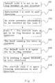
- Figure 3 is a flow chart disclosing the most important steps of the method according to the invention.
- Figure 4 discloses a second embodiment according to the invention, showing a default ring breaker, two faults causing errors and an override ring breaker, all in a non-optical network.
- Figure 5 is a block schematic illustration of an arrangement according to the invention.
- Wavelength Division Multiplexing WDM involves a combination of a set of traffic-bearing optical signals onto a single fiber pair. It is evident that these signals must not interact with each other during transmission and that they must be capable of being separated for reception at the far end. This is achieved by operating each optical signal on a separate wavelength. Many of the channels are so called payload channels and one of the channels is a so-called overhead channel.
- the WDM transport network shown in figure 1 comprises four nodes, called an A-node, a B-node, a C-node and a D-node.
- the nodes A, B, C and D are connected to each other via bi-directional links DC1, DC2, DC3 and DC4.
- the link DC2 for example brings the D-node and the C-node together.
- a first link part DC2a in the schematic figure transports information in a direction from the D-node to the C-node.
- a second link part DC2b of the link DC2 transports information in an opposite direction from the C-node to the D-node.
- Subscriber units 1a, 1b, 1c and 1d are each one connected to one of the nodes A, B, C and D.
- a service telephone channel is embedded in the transport network. The service channel can be accessed at every node A, B, C and D via the subscriber units 1a, 1b, 1c and 1d. It is important that the service telephone channel has a high availability, as it is used during installation and when during trouble shooting of problems with the ring structured network. Therefore it is very useful to protect the telephone channels from breaks in the ordinary transport path.
- Each node comprises two bi-directional ports used to build up the ring-structured network.
- the A-node for example, comprises two bi-directional ports PA1 and PA2.
- the A-node is connected to the B-node by the link DC4, via the bi-directional port PA1.
- the A-node is also connected to the D-node by the link DC1, via the bi-directional port PA2.
- Each one of the nodes A-D is connected to two other nodes A-D via two ports. All nodes A-D are together forming the ring-structured network RING.
- One of the nodes, the A-node is in this embodiment acting as ring breaker in one direction. For the node to act as ring breaker in a direction, relaying of information is prevented in that direction.
- a node only acts as ring breaker in one direction. It is however to be noted that often the node acts as ring breaker in both directions in the ring structure. This will be further discussed in the already mentioned second embodiment where a ring breaker is acting in two directions.
- FIG 1 the fact that the A-node is acting as ring breaker is shown by a ring breaker symbol RBA1 between the A-node and the B-node.
- the ring breaker RBA1 prevents transportation of information between the B-node and the A-node, in direction B to A.
- a ring breaker prevents acoustic feedback in the ring.
- Another ring breaker RBC1 located at the C-node is also shown in figure 1.
- the port PA1 comprises switches SA1 and SA2.
- the location of a switch SC1 belonging to the port PC1 is also shown in the figure and will be explained later.
- the port PA1 will be further discussed together with figure 2a.
- the ring breaker RBA1 is activated and prevents information to be relayed from the B-node to the A-node.
- Information is sent, clockwise in the figure, from the A-node to the B-node. This information can for example be a carrier wave without any other relevant information. Due to an error ERROR, affecting the link DC2a between the D-node and the C-node, the transportation of information is interrupted and the C-node will not receive the sent information.
- the ring network is at this point interrupted in two places, at the A-node and at the link DC2a between the D-node and the C-node.
- a new ring breaker RBC1 will be activated between the D-node and the C-node.
- the new ring breaker RBC1 is located at the C-node and the previous ring breaker RBA1 is removed and information can again be relayed from the B-node to the A-node.
- the new ring breaker is maintained at the C-node.
- the function of the ring breakers RBA1 and RBC1 will be further explained later in the description together with a method according to the invention.
- FIG 2 can be seen an example of a ring breaker. It is to be noted that the ring breaker in figure 2 is preventing information to be relayed in one direction only. As already mentioned however, the ring breakers often work in two directions instead of in only one.
- the switch symbols in the schematic figure 2 is convenient to use when explaining the figures. It is however to be noted that a switch only is a symbol saying that information is relayed or not relayed in a direction. This does not necessarily has to be performed by using a switch, more likely a de-activation of a switch is realized by sending non-relevant information in that direction.
- the node A is connected to the node B and to the node D.
- the subscriber set 1A is connected to the node A.
- the node A is connected to the node B via a first port comprising the two switches SA1 and SA2.
- the node A is connected to the node D via a second port comprising two switches SA3 and SA4.
- the switch SA1 is deactivated.
- the switch SA2 is deactivated when the node breaker is set to prevent transportation of information from node A to node B.
- the switch SA4 is deactivated.
- the switch SA3 is deactivated. Of course, if a node is set to prevent information in two directions, two switches have to be de-activated at the same time.
- the object of the invention is to keep a pre-defined node as ring breaker also after a fault that has occurred, has been amended.
- the most essential steps in the method will be disclosed later in a flow chart in figure 3.
- the method is to be studied together with the already explained figures 1 and 2.
- the node A is at the beginning set to be the node breaker in one direction. This can be seen with the node breaker symbol RBA1 in figure 1.
- the switch SA1 is deactivated as can be seen in figure 2 and information is thereby prevented from being relayed from node B to node A.
- the node A is acting as the so-called default node A.
- the method comprises the following further steps:
- the override node C was affected after an error, to act as ring breaker.
- the ring breaker was thereby positioned at a location close to the error. Since no information can be transferred between D and C in direction D to C as long as the error exists, the error will automatically act as ring breaker. After the fault causing the error has been repaired, the default ring breaker A will again act as ring breaker.
- a release signal RELEASE sent from node-A guarantees that the ring breaker in the override node never is open at the same time as the ring breaker in the default node. This is done by waiting for the release signal before the override node again permits relaying of information.
- a ring structured network TDM in the figure is of a non-optical network type.
- the network is a Time Division Multiplexing network i.e. frames are transported between sites/nodes in the ring structured network. Information that is to be transmitted is divided into time frames and put into a main frame before transportation. Main frames are sent via bi-directional links in both directions in the ring structured network. This is shown by arrow symbols in two directions.
- a number of sites E to N are shown in figure 4.
- all ring breakers work in two directions i.e. prevent information to be relayed in two directions.
- a method according to the invention will now be discussed.
- two errors ERR1 and ERR2 a so called primary error ERR1 and a secondary error ERR2 will arise almost at the same time.
- the site M is acting as ring breaker in both directions and is consequently the default ring breaker M.
- the method comprises the following steps:
- the override site I was affected after an error ERR1, to act as ring breaker and the ring breaker M was released. Thereafter, before ERR1 was mended, a second error ERR2 occurred and affected site F to also act as ring breaker. After the fault causing the errors ERR1 and ERR2 was repaired, the default ring breaker M again will act as ring breaker. Without the return of the ring breaker to the default position - i.e. site M, as shown above, as soon as the errors are mended, would have lead to more than one ring breaker at the same time. This would have caused a situation difficult to handle for operators. It is to be observed that the described embodiment just is an example. Another possible situation, solved by the invention is when more than two errors happen.
- FIG 5 a channel protection arrangement 1 according to the invention is shown.
- the arrangement in this exemplified embodiment comprises the same four nodes A, B, C and D that earlier was explained in the description in the first embodiment.
- the subscriber unit 1A is connected to the A-node.
- the arrangement 1 also comprises a control unit CU. It is to be noted however that this is just an example.
- the control unit CU function can instead be a built in part in each one of the nodes A, B, C, D.
- Each one of the nodes A, B, C and D comprises switches of the type shown earlier in figure 2a. For the sake of clarity of the figure, only two of the switches are disclosed in figure 5.
- the switch SA1 in node A and the switch SC1 in node C are shown in figure 5.
- Each one of the nodes A, B, C and D are connected to the control unit CU.
- the control unit can thereby receive status signals from each node.
- the status signals forward information to the unit CU.
- the control unit is informed of when a node has transmitted information to another node, i.e. which one of the nodes is the target and the destination node.
- the control unit is also informed of when one of the nodes, that the information has to pass, has received the information correctly. If a node is intended to receive but does not receive the information correctly, the control unit gets information about this via the status signals.
- the control unit controls each one of the switches. Each switch can thereby be set in a deactivated or activated position by the control unit.
- a deactivated state is a state when an information signal is not passed on.
- An activated state is the state when the switch is in position to pass on an information signal.
- the switch SA1 is set in its deactivated state while the switch SC1 is set in its activated state.
- the control unit CU waits for signals indicating that one ring breaker is deactivated before it activates another ring breaker.
- control unit CU can be divided and integrated within the sites.
- the number of nodes/sites and links are of course also variable. The invention is thus not restricted to the above described and illustrated exemplifying embodiments, and modifications can be made within the scope of the claims.
Landscapes
- Engineering & Computer Science (AREA)
- Computer Networks & Wireless Communication (AREA)
- Signal Processing (AREA)
- Small-Scale Networks (AREA)
- Emergency Protection Circuit Devices (AREA)
- Channel Selection Circuits, Automatic Tuning Circuits (AREA)
- Use Of Switch Circuits For Exchanges And Methods Of Control Of Multiplex Exchanges (AREA)
Abstract
- Emergence of an error in the ring structured network.
- Locating a site first prevented to receive information (INF) transported in the network, due to the error.
- Influencing the first site, the so called override site, to act as ring breaker, by preventing the site from relaying information in the at least one direction.
- Influencing the default site to permit relaying of information in the at least one direction.
- Mending the error.
- Influencing the default site to act as ring breaker by preventing the site from relaying information in said at least one direction.
- Sending a release signal from the default site to the override site.
- Affecting the override site to permit relaying of information in said at least one direction.
Description
- The default node A is sending an idle signal IDLE in both directions, telling the system that it is the default node. As already said, a schematic switch like SA1 can be realized by the sending of not valid information.
- Information INF is sent in both clockwise and anti-clockwise direction in the traffic channel. The information in the clockwise direction has to pass nodes in the following sequence order: node-A, node-D, node-C and node-B.
- Node D is prepared to receive, and receives the sent information via the link DC1.
- Node C is prepared to receive, but does not receive, the information via the DC2.
- Node C is noted as the first node among the nodes D, C and B not receiving the sent information. This is due to an error which consequently has to be located between node D and node C.
- Node C is pointed out to be a so-called override node. The override node C was intended to receive information - but failed.
- The switch SC1 is deactivated and the override node C acts as ring breaker by preventing the node from relaying information in the above said clockwise direction i.e. from the link DC2a.
- The override node C is sending an override signal OVERRIDE in both directions, telling the system that it is the override node.
- The default node A is affected to permit relaying of information in said direction i.e. from node B to node A. The switch SA1 is activated, i.e. the node A is no longer the ring breaker.
- The fault causing the error between node D and node C is taken care of and the previous error between the nodes D and C ceases to exist.
- The override node C is sending a revert signal REVERT in both directions, telling the system that the fault has been amended.
- The default node A is affected to again act as ring breaker by preventing the site from relaying information in said clockwise direction from node B to node A.
- The default node A is sending a release signal RELEASE in both directions, telling the system that it acts as ring breaker.
- The override node C is affected to permit relaying of information in said direction from node D to node C.
- The override node C is sending an idle signal IDLE in both directions, telling the system that it is in default state.
- The default node A is sending an idle signal IDLE in both directions, telling the system that it is in default state.
- The default node A is set to be ring breaker. A
block 101, in figure 3 illustrates this step. - Information INF is sent in the same direction as the
default node A acts as ring breaker, i.e. in clockwise
direction. A
block 102 illustrates the step. - An error prevents the information from reaching node C.
A
block 103 illustrates the step. - The override node C is set to be the new ring breaker. A
block 104 illustrates the step. - The fault causing the error is taken care of and the
error ceases to exist. A
block 105 illustrates the step. - The default node A is affected to act as ring breaker
again. A
block 106 illustrates the step. - The default node A is sending a release signal RELEASE in both directions, telling the system that it acts as ring breaker.
- The override node C is affected to again permit relaying
of information. A
block 108 illustrates the step.
- The default site M is sending an idle signal IDLE in both directions, telling the system that it is the default site.
- Information INF is sent in the traffic channel in both clockwise and anti-clockwise direction. The information in the clockwise direction has to pass sites in the following oreder M, N, E, F, G, H, I, J, K, L. The information in the anti-clockwise direction has to pass the sites in reversed order i.e. from site L to site M.
- Site F is prepared to receive, and receives also, the sent information via a link between sites E and F that is forwarding information in clockwise direction.
- Site I is prepared to receive, but does not receive, the information via a link that is forwarding information in clockwise direction, between sites H and I.
- Site I is noted to be the first node between M and I, not receiving the sent information. This is due to the primary error ERR1 which consequently has to be located between site H and site I.
- Site I is pointed out to be the so called override site I.
- The override site I acts as ring breaker by preventing information to be relayed in both directions.
- The override site I is sending an override signal OVERRIDE in both directions, telling the system that it is the override site.
- The default site M is affected to permit relaying of information in both directions.
- The secondary error ERR2 occurs in the clockwise direction link between site E and site F.
- Site F is prepared to receive, but does now not receive, information via a link that is forwarding information in the clockwise direction between sites E and F.
- Site F is noted as the first site between M and F, not receiving the sent information due to the secondary error ERR2 which consequently has to be located between site E and site F.
- Site F is pointed out to be the so called second override site F.
- The override site F is affected to act as ring breaker by preventing the site from relaying information in both directions.
- The override site F is sending an override signal OVERRIDE in both directions, telling the system that it is the second override site.
- The fault causing the error between site E and site F is repaired.
- The second override site F is sending a revert signal REVERT in both directions, telling the system that the fault has been amended.
- The fault causing the error between site H and site I is repaired.
- The override site I is sending a revert signal REVERT in both directions, telling the system that the fault has been amended.
- The default site M is affected to again act as ring breaker.
- The default site M is sending a release signal RELEASE in both directions, telling the system that it acts as ring breaker.
- The override site I is affected to permit relaying of information in said direction from site H to site I.
- The override site I is sending an idle signal IDLE in both directions, telling the system that it is in default state.
- The override site F is affected to permit relaying of information in said direction from site H to site I.
- The override site F is sending an idle signal IDLE in both directions, telling the system that it is in default state.
- The default node A is sending an idle signal IDLE in both directions, telling the system that it is in default state.
Claims (20)
- Method to protect a communication channel in a transport network (RING), which network comprises network sites (A,B,C,D) arranged via bi-directional links in a ring structure, whereby one of the sites, a default site (A), is acting as ring breaker by preventing relaying of information in at least one direction, which method comprises the following steps:emergence of an error (ERROR) in the ring structured network (RING);locating an override site (C) first prevented to receive information (INF) transported in the network, due to the error;influencing the override site (C) to act as ring breaker, by preventing the site (C) from relaying information in the at least one direction;influencing the default site (A) to permit relaying of information in the at least one direction.mending of the error, whereby the method is characterised by:influencing the default site (A) to act as ring breaker by preventing the site from relaying information in said at least one direction.
- Method to protect a communication channel in accordance with claim 1, which method comprises the following further step:affecting the override site (C) to permit relaying of information in said at least one direction.
- Method to protect a communication channel in accordance with claim 2, whereby the affecting of the override site (C) to permit relaying is preceded by the following step:sending a release signal (RELEASE) from the default site (A) to the override site (C).
- Method to protect a communication channel in accordance with any of the claims 1 to 3, whereby the communication channel in the transport network (RING) is an embedded service telephone channel.
- Method to protect a communication channel in a transport network (RING), which network comprises network sites (A,B,C,D) arranged via bi-directional links in a ring structure, whereby one of the sites, a default site (A), is acting as ring breaker by preventing relaying of information in one direction, which method comprises the following steps:emergence of an error (ERROR) in the ring structured network (RING), in said direction;locating an override site (C) first prevented to receive information (INF) transported in the network, due to the error;influencing the override site (C), to act as ring breaker, by preventing the site (C) from relaying information in said direction;influencing the default site (A) to permit relaying of information in said direction.mending of the error, whereby the method is characterised by:influencing the default site (A) to act as ring breaker by preventing the site from relaying information in said direction.
- Method to protect a communication channel in accordance with claim 5, which method comprises the following further step:affecting the override site (C) to permit relaying of information in said direction.
- Method to protect a communication channel in accordance with claim 6, whereby the affecting of the override site (C) to permit relaying is preceded by the following step:sending a release signal (RELEASE) from the default site (A) to the override site (C).
- Method to protect a communication channel in accordance with any of the claims 5 to 7, whereby the communication channel in the transport network (RING) is an embedded service telephone channel.
- Method to protect a communication channel in accordance with any of the claims 1 to 8, which method comprises following further steps:Sending an idle signal IDLE from the default node A, telling the system that it is the default node;Sending an override signal OVERRIDE from the override node C, telling the system that it is the override node;Sending a revert signal REVERT, telling the system that the error was mended;Sending an idle signal IDLE by the override node (C) telling the system that it is in a default state;Sending an idle signal IDLE by the default node (A) telling the system that it is in a default state.
- Method in accordance with any of claims 1 to 9, whereby the transport network being a wavelength division multiplexing network.
- Method in accordance with any of claims 1 to 9, whereby the transport network being a time division multiplexing access network.
- Method to protect a communication channel in a transport network (TDM), which network comprises network sites (E-N) arranged via bi-directional links in a ring structure, whereby one of the sites, a default site (M), is acting as ring breaker by preventing relaying of information in at least one direction, which method comprises the following steps:emergence of a primary error (ERR1) in the ring structured network (TDM);locating a site (I), the so called override site (I), first prevented to receive information transported in the network, due to the primary error;influencing the override site (I), to act as ring breaker, by preventing the site (I) from relaying information in the at least one direction;influencing the default site (M) to permit relaying of information in the at least one direction;emergence of a secondary error (ERR2) in the ring structured network (TDM);locating a site (F), first prevented to receive information transported in the network, due to the secondary error (ERR2), the so called second override site (F);influencing the second override site (F) to act as second ring breaker, by preventing the site (F) from relaying information in the at least one direction;mending of the primary error (ERR1) ;affecting the first override site (I) to permit relaying of information.Mending of the secondary error (ERR2), whereby the method is characterised by:influencing the default site (M) to act as ring breaker by preventing the site from relaying information in said at least one direction.
- Method to protect a communication channel in accordance with claim 12, which method comprises the following further step:affecting the override site (F) to permit relaying of information.
- Method to protect a communication channel in accordance with claim 13, whereby the affecting of the override site (F) to permit relaying is preceded by the following step:sending of a release signal (RELEASE) from the default site (M) to the override site (F).
- Method in accordance with any of claims 12 to 14, whereby the transport network being a wavelength division multiplexing network.
- Method in accordance with any of claims 12 to 14, whereby the transport network being a time division multiplexing access network.
- Arrangement to protect a communication channel in a transport network (RING), which network comprises network sites (A,B,C,D) arranged via bi-directional links in a ring structure, whereby one of the sites, a default site (A), is acting as ring breaker by preventing relaying of information in at least one direction, which method comprises the following steps:means for locating a site, an override site (C), first prevented to receive information (INF) in said one direction due to an error;means for affecting the override site (C) to act as ring breaker, by preventing the site (C) from relaying information in the at least one direction;means for affecting the default site (A) to permit relaying of information in the at least one direction.means for registration of ceasing of an error;means for affecting the default site (A) to act as ring breaker by preventing the site from relaying information in said at least one direction.
- Arrangement to protect a communication channel in accordance with claim 17, comprising means for sending a release signal (RELEASE) from the default site (A) to the override site (C) and means for affecting the override site (C) to permit relaying of information in said at least one direction.
- Arrangement in accordance with any of claims 17 to 18, whereby the transport network being a wavelength division multiplexing network.
- Arrangement in accordance with any of claims 17 to 18, whereby the transport network being a time division multiplexing access network.
Priority Applications (3)
| Application Number | Priority Date | Filing Date | Title |
|---|---|---|---|
| AT00850080T ATE371999T1 (en) | 2000-05-10 | 2000-05-10 | CHANNEL PROTECTION |
| DE60036196T DE60036196T2 (en) | 2000-05-10 | 2000-05-10 | channel protection |
| EP00850080A EP1154592B1 (en) | 2000-05-10 | 2000-05-10 | Channel protection |
Applications Claiming Priority (1)
| Application Number | Priority Date | Filing Date | Title |
|---|---|---|---|
| EP00850080A EP1154592B1 (en) | 2000-05-10 | 2000-05-10 | Channel protection |
Publications (2)
| Publication Number | Publication Date |
|---|---|
| EP1154592A1 true EP1154592A1 (en) | 2001-11-14 |
| EP1154592B1 EP1154592B1 (en) | 2007-08-29 |
Family
ID=8175661
Family Applications (1)
| Application Number | Title | Priority Date | Filing Date |
|---|---|---|---|
| EP00850080A Expired - Lifetime EP1154592B1 (en) | 2000-05-10 | 2000-05-10 | Channel protection |
Country Status (3)
| Country | Link |
|---|---|
| EP (1) | EP1154592B1 (en) |
| AT (1) | ATE371999T1 (en) |
| DE (1) | DE60036196T2 (en) |
Cited By (3)
| Publication number | Priority date | Publication date | Assignee | Title |
|---|---|---|---|---|
| CN100555976C (en) * | 2006-02-24 | 2009-10-28 | 阿拉克斯拉网络株式会社 | Ring Network and Masternodes |
| CN102026042A (en) * | 2009-09-18 | 2011-04-20 | 中兴通讯股份有限公司 | Keep-alive and self-healing method and device for advanced telecom computing architecture control surface |
| CN101321031B (en) * | 2008-07-16 | 2011-12-07 | 中兴通讯股份有限公司 | Sharing protection method and system for wavelength division multiplexing looped network |
Citations (4)
| Publication number | Priority date | Publication date | Assignee | Title |
|---|---|---|---|---|
| US5657321A (en) * | 1993-04-19 | 1997-08-12 | Hitachi, Ltd. | Looped bus system for connecting plural nodes or plural circuit cards |
| US5680235A (en) * | 1995-04-13 | 1997-10-21 | Telefonaktiebolaget Lm Ericsson | Optical multichannel system |
| WO1999003230A1 (en) * | 1997-07-11 | 1999-01-21 | Telefonaktiebolaget Lm Ericsson (Publ) | Self-healing ring network and a method for fault detection and rectifying |
| US6052210A (en) * | 1998-01-14 | 2000-04-18 | Mci Communications Corporation | System and method for increasing the robustness of an optical ring network |
-
2000
- 2000-05-10 AT AT00850080T patent/ATE371999T1/en not_active IP Right Cessation
- 2000-05-10 EP EP00850080A patent/EP1154592B1/en not_active Expired - Lifetime
- 2000-05-10 DE DE60036196T patent/DE60036196T2/en not_active Expired - Lifetime
Patent Citations (4)
| Publication number | Priority date | Publication date | Assignee | Title |
|---|---|---|---|---|
| US5657321A (en) * | 1993-04-19 | 1997-08-12 | Hitachi, Ltd. | Looped bus system for connecting plural nodes or plural circuit cards |
| US5680235A (en) * | 1995-04-13 | 1997-10-21 | Telefonaktiebolaget Lm Ericsson | Optical multichannel system |
| WO1999003230A1 (en) * | 1997-07-11 | 1999-01-21 | Telefonaktiebolaget Lm Ericsson (Publ) | Self-healing ring network and a method for fault detection and rectifying |
| US6052210A (en) * | 1998-01-14 | 2000-04-18 | Mci Communications Corporation | System and method for increasing the robustness of an optical ring network |
Cited By (3)
| Publication number | Priority date | Publication date | Assignee | Title |
|---|---|---|---|---|
| CN100555976C (en) * | 2006-02-24 | 2009-10-28 | 阿拉克斯拉网络株式会社 | Ring Network and Masternodes |
| CN101321031B (en) * | 2008-07-16 | 2011-12-07 | 中兴通讯股份有限公司 | Sharing protection method and system for wavelength division multiplexing looped network |
| CN102026042A (en) * | 2009-09-18 | 2011-04-20 | 中兴通讯股份有限公司 | Keep-alive and self-healing method and device for advanced telecom computing architecture control surface |
Also Published As
| Publication number | Publication date |
|---|---|
| ATE371999T1 (en) | 2007-09-15 |
| EP1154592B1 (en) | 2007-08-29 |
| DE60036196T2 (en) | 2008-05-21 |
| DE60036196D1 (en) | 2007-10-11 |
Similar Documents
| Publication | Publication Date | Title |
|---|---|---|
| RU2157595C2 (en) | Device, system and method for remote communication to upgraded signal transmission center | |
| EP0605795B1 (en) | Ring network overhead handling method | |
| US5341364A (en) | Distributed switching in bidirectional multiplex section-switched ringtransmission systems | |
| US5903370A (en) | System for an optical domain | |
| JP3734618B2 (en) | Communication network and protection switching method thereof | |
| US6327260B1 (en) | Controlled routing to a plurality of signaling interfaces at a single telephonic switch | |
| US20110063971A1 (en) | Data relay apparatus, and ring-type communication system | |
| US20040076114A1 (en) | Method and apparatus for shared protection in an optical transport network ring based on the ODU management | |
| US7756416B2 (en) | Optical communication node and optical network system | |
| EP2312792B1 (en) | Protection protocol device for network node and method for processing protection switching thereof | |
| WO1999003230A1 (en) | Self-healing ring network and a method for fault detection and rectifying | |
| US7187649B1 (en) | Method and apparatus for providing network protection at input/output interfaces of a cross-connect switch | |
| EP1154592B1 (en) | Channel protection | |
| US20030009599A1 (en) | Protecting ring network data | |
| KR100340725B1 (en) | Method for management and auto protection switching of signal path in optical transmission system for subscriber service | |
| JP5006342B2 (en) | Exchange system | |
| US6622258B1 (en) | Data protection in a ring network | |
| US8724984B1 (en) | Automated notification of upcoming network disruptive maintenance events to allow traffic to be rerouted | |
| US20030039433A1 (en) | Optical communication circuit | |
| WO2000031927A1 (en) | Method for establishing alternative routes in a telecommunication network | |
| EP1133853A1 (en) | Method for establishing alternative routes in a telecommunication network | |
| JP2000312169A (en) | Communication system, method therefor and communication station unit | |
| JP2005354592A (en) | Optical transmission device, optical transmission method, and optical transmission system | |
| JPH0342930A (en) | Line switching device | |
| WO2002007348A1 (en) | Hybrid optical shared protection ring |
Legal Events
| Date | Code | Title | Description |
|---|---|---|---|
| PUAI | Public reference made under article 153(3) epc to a published international application that has entered the european phase |
Free format text: ORIGINAL CODE: 0009012 |
|
| AK | Designated contracting states |
Kind code of ref document: A1 Designated state(s): AT BE CH CY DE DK ES FI FR GB GR IE IT LI LU MC NL PT SE |
|
| AX | Request for extension of the european patent |
Free format text: AL;LT;LV;MK;RO;SI |
|
| 17P | Request for examination filed |
Effective date: 20020412 |
|
| AKX | Designation fees paid |
Free format text: AT BE CH CY DE DK ES FI FR GB GR IE IT LI LU MC NL PT SE |
|
| RAP1 | Party data changed (applicant data changed or rights of an application transferred) |
Owner name: TELEFONAKTIEBOLAGET LM ERICSSON (PUBL) |
|
| 17Q | First examination report despatched |
Effective date: 20061005 |
|
| GRAP | Despatch of communication of intention to grant a patent |
Free format text: ORIGINAL CODE: EPIDOSNIGR1 |
|
| GRAS | Grant fee paid |
Free format text: ORIGINAL CODE: EPIDOSNIGR3 |
|
| GRAA | (expected) grant |
Free format text: ORIGINAL CODE: 0009210 |
|
| AK | Designated contracting states |
Kind code of ref document: B1 Designated state(s): AT BE CH CY DE DK ES FI FR GB GR IE IT LI LU MC NL PT SE |
|
| REG | Reference to a national code |
Ref country code: GB Ref legal event code: FG4D |
|
| REG | Reference to a national code |
Ref country code: CH Ref legal event code: EP |
|
| REG | Reference to a national code |
Ref country code: IE Ref legal event code: FG4D |
|
| REF | Corresponds to: |
Ref document number: 60036196 Country of ref document: DE Date of ref document: 20071011 Kind code of ref document: P |
|
| PG25 | Lapsed in a contracting state [announced via postgrant information from national office to epo] |
Ref country code: FI Free format text: LAPSE BECAUSE OF FAILURE TO SUBMIT A TRANSLATION OF THE DESCRIPTION OR TO PAY THE FEE WITHIN THE PRESCRIBED TIME-LIMIT Effective date: 20070829 Ref country code: NL Free format text: LAPSE BECAUSE OF FAILURE TO SUBMIT A TRANSLATION OF THE DESCRIPTION OR TO PAY THE FEE WITHIN THE PRESCRIBED TIME-LIMIT Effective date: 20070829 Ref country code: ES Free format text: LAPSE BECAUSE OF FAILURE TO SUBMIT A TRANSLATION OF THE DESCRIPTION OR TO PAY THE FEE WITHIN THE PRESCRIBED TIME-LIMIT Effective date: 20071210 |
|
| NLV1 | Nl: lapsed or annulled due to failure to fulfill the requirements of art. 29p and 29m of the patents act | ||
| ET | Fr: translation filed | ||
| PG25 | Lapsed in a contracting state [announced via postgrant information from national office to epo] |
Ref country code: CH Free format text: LAPSE BECAUSE OF FAILURE TO SUBMIT A TRANSLATION OF THE DESCRIPTION OR TO PAY THE FEE WITHIN THE PRESCRIBED TIME-LIMIT Effective date: 20070829 Ref country code: LI Free format text: LAPSE BECAUSE OF FAILURE TO SUBMIT A TRANSLATION OF THE DESCRIPTION OR TO PAY THE FEE WITHIN THE PRESCRIBED TIME-LIMIT Effective date: 20070829 Ref country code: AT Free format text: LAPSE BECAUSE OF FAILURE TO SUBMIT A TRANSLATION OF THE DESCRIPTION OR TO PAY THE FEE WITHIN THE PRESCRIBED TIME-LIMIT Effective date: 20070829 |
|
| REG | Reference to a national code |
Ref country code: CH Ref legal event code: PL |
|
| PG25 | Lapsed in a contracting state [announced via postgrant information from national office to epo] |
Ref country code: BE Free format text: LAPSE BECAUSE OF FAILURE TO SUBMIT A TRANSLATION OF THE DESCRIPTION OR TO PAY THE FEE WITHIN THE PRESCRIBED TIME-LIMIT Effective date: 20070829 |
|
| PG25 | Lapsed in a contracting state [announced via postgrant information from national office to epo] |
Ref country code: GR Free format text: LAPSE BECAUSE OF FAILURE TO SUBMIT A TRANSLATION OF THE DESCRIPTION OR TO PAY THE FEE WITHIN THE PRESCRIBED TIME-LIMIT Effective date: 20071130 Ref country code: DK Free format text: LAPSE BECAUSE OF FAILURE TO SUBMIT A TRANSLATION OF THE DESCRIPTION OR TO PAY THE FEE WITHIN THE PRESCRIBED TIME-LIMIT Effective date: 20070829 |
|
| PG25 | Lapsed in a contracting state [announced via postgrant information from national office to epo] |
Ref country code: PT Free format text: LAPSE BECAUSE OF FAILURE TO SUBMIT A TRANSLATION OF THE DESCRIPTION OR TO PAY THE FEE WITHIN THE PRESCRIBED TIME-LIMIT Effective date: 20080129 |
|
| PG25 | Lapsed in a contracting state [announced via postgrant information from national office to epo] |
Ref country code: SE Free format text: LAPSE BECAUSE OF FAILURE TO SUBMIT A TRANSLATION OF THE DESCRIPTION OR TO PAY THE FEE WITHIN THE PRESCRIBED TIME-LIMIT Effective date: 20071129 |
|
| PLBE | No opposition filed within time limit |
Free format text: ORIGINAL CODE: 0009261 |
|
| STAA | Information on the status of an ep patent application or granted ep patent |
Free format text: STATUS: NO OPPOSITION FILED WITHIN TIME LIMIT |
|
| 26N | No opposition filed |
Effective date: 20080530 |
|
| PG25 | Lapsed in a contracting state [announced via postgrant information from national office to epo] |
Ref country code: MC Free format text: LAPSE BECAUSE OF NON-PAYMENT OF DUE FEES Effective date: 20080531 |
|
| PG25 | Lapsed in a contracting state [announced via postgrant information from national office to epo] |
Ref country code: IE Free format text: LAPSE BECAUSE OF NON-PAYMENT OF DUE FEES Effective date: 20080512 |
|
| PG25 | Lapsed in a contracting state [announced via postgrant information from national office to epo] |
Ref country code: CY Free format text: LAPSE BECAUSE OF FAILURE TO SUBMIT A TRANSLATION OF THE DESCRIPTION OR TO PAY THE FEE WITHIN THE PRESCRIBED TIME-LIMIT Effective date: 20070829 |
|
| PG25 | Lapsed in a contracting state [announced via postgrant information from national office to epo] |
Ref country code: LU Free format text: LAPSE BECAUSE OF NON-PAYMENT OF DUE FEES Effective date: 20080510 |
|
| REG | Reference to a national code |
Ref country code: FR Ref legal event code: PLFP Year of fee payment: 16 |
|
| PGFP | Annual fee paid to national office [announced via postgrant information from national office to epo] |
Ref country code: DE Payment date: 20150528 Year of fee payment: 16 Ref country code: GB Payment date: 20150527 Year of fee payment: 16 |
|
| PGFP | Annual fee paid to national office [announced via postgrant information from national office to epo] |
Ref country code: FR Payment date: 20150519 Year of fee payment: 16 Ref country code: IT Payment date: 20150527 Year of fee payment: 16 |
|
| REG | Reference to a national code |
Ref country code: DE Ref legal event code: R119 Ref document number: 60036196 Country of ref document: DE |
|
| GBPC | Gb: european patent ceased through non-payment of renewal fee |
Effective date: 20160510 |
|
| PG25 | Lapsed in a contracting state [announced via postgrant information from national office to epo] |
Ref country code: IT Free format text: LAPSE BECAUSE OF NON-PAYMENT OF DUE FEES Effective date: 20160510 |
|
| REG | Reference to a national code |
Ref country code: FR Ref legal event code: ST Effective date: 20170131 |
|
| PG25 | Lapsed in a contracting state [announced via postgrant information from national office to epo] |
Ref country code: DE Free format text: LAPSE BECAUSE OF NON-PAYMENT OF DUE FEES Effective date: 20161201 Ref country code: FR Free format text: LAPSE BECAUSE OF NON-PAYMENT OF DUE FEES Effective date: 20160531 |
|
| PG25 | Lapsed in a contracting state [announced via postgrant information from national office to epo] |
Ref country code: GB Free format text: LAPSE BECAUSE OF NON-PAYMENT OF DUE FEES Effective date: 20160510 |