EP1154501A2 - Method for manufacturing electrode plate for battery - Google Patents
Method for manufacturing electrode plate for battery Download PDFInfo
- Publication number
- EP1154501A2 EP1154501A2 EP01111346A EP01111346A EP1154501A2 EP 1154501 A2 EP1154501 A2 EP 1154501A2 EP 01111346 A EP01111346 A EP 01111346A EP 01111346 A EP01111346 A EP 01111346A EP 1154501 A2 EP1154501 A2 EP 1154501A2
- Authority
- EP
- European Patent Office
- Prior art keywords
- cut
- electrode sheet
- electrode
- sides
- regions
- Prior art date
- Legal status (The legal status is an assumption and is not a legal conclusion. Google has not performed a legal analysis and makes no representation as to the accuracy of the status listed.)
- Granted
Links
Images


Classifications
-
- H—ELECTRICITY
- H01—ELECTRIC ELEMENTS
- H01M—PROCESSES OR MEANS, e.g. BATTERIES, FOR THE DIRECT CONVERSION OF CHEMICAL ENERGY INTO ELECTRICAL ENERGY
- H01M4/00—Electrodes
- H01M4/02—Electrodes composed of, or comprising, active material
- H01M4/24—Electrodes for alkaline accumulators
- H01M4/26—Processes of manufacture
-
- H—ELECTRICITY
- H01—ELECTRIC ELEMENTS
- H01M—PROCESSES OR MEANS, e.g. BATTERIES, FOR THE DIRECT CONVERSION OF CHEMICAL ENERGY INTO ELECTRICAL ENERGY
- H01M4/00—Electrodes
- H01M4/02—Electrodes composed of, or comprising, active material
- H01M4/04—Processes of manufacture in general
-
- Y—GENERAL TAGGING OF NEW TECHNOLOGICAL DEVELOPMENTS; GENERAL TAGGING OF CROSS-SECTIONAL TECHNOLOGIES SPANNING OVER SEVERAL SECTIONS OF THE IPC; TECHNICAL SUBJECTS COVERED BY FORMER USPC CROSS-REFERENCE ART COLLECTIONS [XRACs] AND DIGESTS
- Y02—TECHNOLOGIES OR APPLICATIONS FOR MITIGATION OR ADAPTATION AGAINST CLIMATE CHANGE
- Y02E—REDUCTION OF GREENHOUSE GAS [GHG] EMISSIONS, RELATED TO ENERGY GENERATION, TRANSMISSION OR DISTRIBUTION
- Y02E60/00—Enabling technologies; Technologies with a potential or indirect contribution to GHG emissions mitigation
- Y02E60/10—Energy storage using batteries
-
- Y—GENERAL TAGGING OF NEW TECHNOLOGICAL DEVELOPMENTS; GENERAL TAGGING OF CROSS-SECTIONAL TECHNOLOGIES SPANNING OVER SEVERAL SECTIONS OF THE IPC; TECHNICAL SUBJECTS COVERED BY FORMER USPC CROSS-REFERENCE ART COLLECTIONS [XRACs] AND DIGESTS
- Y10—TECHNICAL SUBJECTS COVERED BY FORMER USPC
- Y10T—TECHNICAL SUBJECTS COVERED BY FORMER US CLASSIFICATION
- Y10T29/00—Metal working
- Y10T29/49—Method of mechanical manufacture
- Y10T29/49002—Electrical device making
- Y10T29/49108—Electric battery cell making
- Y10T29/49115—Electric battery cell making including coating or impregnating
-
- Y—GENERAL TAGGING OF NEW TECHNOLOGICAL DEVELOPMENTS; GENERAL TAGGING OF CROSS-SECTIONAL TECHNOLOGIES SPANNING OVER SEVERAL SECTIONS OF THE IPC; TECHNICAL SUBJECTS COVERED BY FORMER USPC CROSS-REFERENCE ART COLLECTIONS [XRACs] AND DIGESTS
- Y10—TECHNICAL SUBJECTS COVERED BY FORMER USPC
- Y10T—TECHNICAL SUBJECTS COVERED BY FORMER US CLASSIFICATION
- Y10T83/00—Cutting
- Y10T83/929—Tool or tool with support
- Y10T83/9411—Cutting couple type
Definitions
- the present invention relates to a method for manufacturing an electrode plate for a battery. More specifically, the present invention relates to a method for manufacturing an electrode plate for a battery that can reduce the short-circuit failure between electrode plates after incorporation into a battery.
- An electrode plate used in these batteries is provided by cutting a flat electrode sheet to a predetermined size.
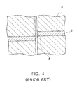
- the following is a conventional method for cutting an electrode plate for a battery: as shown in FIGS. 4 and 5, the entire regions on both sides of a portion to be cut 4 of an electrode sheet 3 are each fixed between a pair of upper and lower flat cutting dies 6 having the same area as an electrode plate; two adjacent pairs of upper and lower cutting dies 6 on both sides of the portion to be cut 4 are moved perpendicularly to the electrode sheet 3 in opposite directions (upward and downward), and thus the electrode sheet 3 is cut to a predetermined size.
- a method for reducing the thickness of the portion of the electrode sheet to be cut has been proposed as well.
- the above conventional cutting method causes the adhesion of foreign materials to the electrode plate surface and an edge burr, which are largely responsible for the short-circuit failure between electrode plates after incorporation into a battery.
- the adhesion of foreign materials to the electrode plate surface occurs because fragments are pressed on the electrode plate surface by the cutting dies when the electrode sheet is cut with the adjacent flat cutting dies being in contact with the entire regions on both sides of the portion to be cut.
- the edge burr is generated when the flat electrode sheet is cut.
- the edge burr occurs because the thin portion is bent during cutting and the burrs are not suppressed completely.
- an object of the present invention to provide a method for manufacturing an electrode plate for a battery that can reduce the short-circuit failure between electrode plates after incorporation into a battery by suppressing the adhesion of fragments to the electrode plate surface and the generation of burrs.
- a method for manufacturing an electrode plate for a battery of the present invention includes cutting an electrode sheet containing an active material to a predetermined size with cutting dies.
- the regions on both sides of and close to a portion of the electrode sheet to be cut are each fixed between a pair of cutting dies.
- Two adjacent pairs of cutting dies on both sides of the portion to be cut are moved perpendicularly to the electrode sheet in opposite directions to each other, and thus the electrode sheet is cut.
- This method can lower the frequency with which fragments produced in cutting the electrode sheet are pressed on the electrode plate surface by the cutting dies, thus reducing the adhesion of foreign materials to the electrode plate surface.
- the short-circuit failure between electrode plates can be reduced after the electrode group produced in the above manner has been incorporated into a battery.
- the region close to a portion to be cut refers to the region within about one-tenth of the width and one-twentieth of the length of the electrode plate cut (hereinafter, used in the same way).
- the portion of the electrode sheet to be cut and the regions on both sides of and close to that portion are formed previously so as to have a thickness smaller than that of the electrode sheet body, and when the electrode sheet is cut, the thin regions on both sides of the portion to be cut are each fixed between a pair of cutting dies.
- This preferred example can reduce the adhesion of foreign materials on the electrode plate surface and prevent burrs from being generated on the electrode surface as well. The reason for this is as follows: since a three-dimensional porous metal substrate is in sponge form, it is hardened by reducing the thickness; in addition, a surface burr (the height of a burr from the electrode plate surface) tends to be higher with increasing thickness of the substrate.
- the short-circuit failure between electrode plates can be reduced further after the electrode group produced in the above manner has been incorporated into a battery.
- the thickness of the thin region is one-half to one-fifth of that of the electrode sheet body. Though the burrs are not generated readily with reducing the thickness of the substrate, an excessive reduction in thickness makes cutting difficult.
- the portion of the electrode sheet to be cut and the regions on both sides of and close to that portion are formed to be thin by pressing.
- the electrode sheet is formed by filling a substrate of three-dimensional porous metal body with the active material.
- the electrode sheet is formed by filling a substrate of three-dimensional porous metal body with the active material, and that the regions on both sides of and close to the portion of the electrode sheet to be cut are coated with resin or impregnated with a liquid containing a resin component before cutting the electrode sheet.
- This preferred example can reduce the adhesion of foreign materials to the electrode plate surface and prevent burrs from being generated on the electrode plate surface as well.
- the method includes the following steps in no special order before cutting the electrode sheet: a step of coating the regions on both sides of and close to the portion of the electrode sheet to be cut with resin or a step of impregnating the regions with a liquid containing a resin component, and a step of forming the portion of the electrode sheet to be cut and the regions on both sides of and close to that portion so as to have a thickness smaller than that of the electrode sheet body.
- This preferred example further can reduce the adhesion of foreign materials to the electrode plate surface and prevent burrs from being generated on the electrode plate surface as well.
- the electrode sheet is formed by applying the active material to a core material of punching metal, that a region to which no active material is applied is provided previously in the portion of the electrode sheet to be cut and the regions on both sides of and close to that portion, and when the electrode sheet is cut, the regions with no active material on both sides of the portion to be cut are each fixed between a pair of cutting dies.
- This preferred example can reduce the adhesion of foreign materials to the electrode plate surface.
- burrs generated on the electrode plate surface can be prevented as well.
- the short-circuit failure between electrode plates further can be reduced after the electrode group produced in the above manner has been incorporated into a battery.
- the present invention can prevent fragments of the electrode sheet from being pressed on the electrode plate surface to form foreign materials thereon and burrs from being generated on the electrode plate surface.
- the short circuits of the electrode group for a battery can be suppressed.
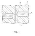
- FIG. 1 is a schematic cross-sectional view showing an electrode sheet and cutting dies used in an embodiment of the present invention.
- FIG. 2 is a schematic plan view showing an electrode sheet and cutting dies used in an embodiment of the present invention.
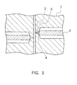
- FIG. 3 is a schematic cross-sectional view showing another electrode sheet and cutting dies used in an embodiment of the present invention.
- FIG. 4 is a schematic cross-sectional view showing an electrode sheet and cutting dies used in the prior art.
- FIG. 5 is a schematic plan view showing an electrode sheet and cutting dies used in the prior art.
- a method for manufacturing an electrode plate for a battery of the present invention is such that an electrode sheet containing an active material is cut to a predetermined size with cutting dies, resulting in an electrode plate for a battery.
- the regions on both sides of and close to a portion of the electrode sheet to be cut are each fixed between the cutting edges of a pair of upper and lower cutting dies.
- two adjacent pairs of upper and lower cutting dies on both sides of the portion to be cut are moved perpendicularly to the electrode sheet in opposite directions (upward and downward).
- the electrode sheet is cut.
- This cutting method can lower the frequency with which fragments produced in cutting the electrode sheet are pressed on the electrode plate surface by the cutting dies, thus reducing the adhesion of foreign materials to the electrode plate surface. As a result, the short-circuit failure between electrode plates can be reduced after the electrode group produced in the above manner has been incorporated into a battery.
- the portion of the electrode sheet to be cut and the regions on both sides of and close to that portion are formed previously so as to have a thickness smaller than that of the electrode sheet body, and when the electrode sheet is cut, the thin regions on both sides of the portion to be cut are each fixed between a pair of cutting dies.
- This cutting method can reduce the adhesion of foreign materials to the electrode plate surface and prevent burrs from being generated on the electrode plate surface as well.
- the short-circuit failure between electrode plates further can be reduced after the electrode group produced in the above manner has been incorporated into a battery.
- the burrs generated in cutting the electrode sheet are increased in proportion to the thickness of the electrode sheet around the portion to be cut, it is desirable that the portion of the electrode sheet to be cut and the regions on both sides of and close to that portion have a thickness smaller than that of the electrode sheet body, and more desirably, the thickness is about one-half to one-fifth of that of the electrode sheet body.
- the regions on both sides of and close to the portion of the electrode sheet to be cut are coated with resin beforehand. This can prevent needle-shaped burrs from being generated at the ends of a cutting plane. Even if such burrs are caused, the short-circuit failure between electrode plates can be reduced after the electrode group has been incorporated into a battery because the ends of the burrs are covered with insulating resin.
- the regions on both sides of and close to the portion of the electrode sheet to be cut are impregnated with a liquid containing a resin component beforehand.
- a liquid containing a resin component a liquid in which a resin component is dissolved or dispersed, having a relatively low viscosity, may be applied or sprayed.
- This method allows the skeleton metal, which is located on both sides of and close to the portion to be cut, to be bonded more firmly and shaped to be thinner by pressing.
- this portion is coated with insulating resin.
- the electrode sheet is formed by applying the active material to a core material of punching metal, that a region to which no active material is applied (a plain region) is provided previously in the portion of the electrode sheet to be cut and the regions on both sides of and close to that portion, and when the electrode sheet is cut, the plain regions on both sides of the portion to be cut are each fixed between a pair of upper and lower cutting dies.
- This cutting method can reduce the adhesion of foreign materials to the electrode plate surface.
- the plain region is cut, the burrs generated on the electrode plate surface can be prevented as well. Consequently, the short-circuit failure between electrode plates further can be reduced after the electrode group produced in the above manner has been incorporated into a battery.
- FIG. 1 is a schematic cross-sectional view showing an electrode sheet and cutting dies used in this example;
- FIG. 2 is a schematic plan view showing the same.
- numeral 1 indicates a pair of upper and lower cutting dies.
- Numeral 3 is an electrode sheet, and a pair of upper and lower cutting dies 1 is placed on both sides of a portion to be cut 4 of the electrode sheet 3.
- Each of the upper and lower cutting dies 1 has a cutting edge 2 that is provided around the periphery of an electrode plate.
- the regions on both sides of and close to the portion to be cut 4 of the electrode sheet 3 are each fixed between a pair of upper and lower cutting edges 2.
- a width of the cutting edge 2 of the cutting die 1 is 1.0 ⁇ 0.5 mm.
- nickel hydroxide 100 parts by weight was mixed with 10 parts by weight of nickel metal powder and 5 parts by weight of cobalt oxide powder. To this was added water as a dispersion medium so as to account for 30 weight % of the total paste, which then was kneaded into an active material in paste form.
- the paste active material thus prepared was placed in a tank.
- a filling nozzle connected to the tank was opposed to a spongy three-dimensional porous nickel metal body to be filled with the paste active material.
- the spongy three-dimensional porous nickel metal body was belt-shaped, having a width of 110 mm, length of 210 mm, thickness of 1.0 mm, porosity of 98 %, and average pore size of 100 ⁇ m.
- the filling nozzle delivered a certain amount of active material, 9 to 10 g/sheet, to fill the spongy porous nickel metal body. Thereafter, the spongy porous nickel metal body was pressed so that the whole thickness was 0.50 mm, resulting in the electrode sheet 3 (see FIG. 1).
- the regions on both sides of and close to the portion to be cut 4 of the electrode sheet 3 were each fixed between the cutting edges 2 of a pair of upper and lower cutting dies 1, i.e., the cutting edges 2 of the adjacent cutting dies 1 were in contact with only the regions on both sides of and close to the portion to be cut 4.
- two adjacent pairs of upper and lower cutting dies 1 on both sides of the portion to be cut 4 were moved perpendicularly to the electrode sheet 3 in opposite directions (upward and downward).
- the electrode sheet 3 was cut at the portion to be cut 4, resulting in nickel electrode plates having a width of 50 mm and length of 100 mm.
- Short-circuit tests were conducted on the electrode group by measuring its resistance under a load of 300 kg ⁇ f (2,940 N), which was substantially equal to the pressure to which the electrode group was subjected when it was incorporated into a battery.
- the same short-circuit tests were conducted on an electrode group having the same configuration as that in this example, except for the use of nickel electrode plates provided in the following manner: the entire regions on both sides of a portion to be cut 4 of an electrode sheet 3 were each fixed between a pair of upper and lower flat cutting dies 6 having the same area as an electrode plate, i.e., the adjacent flat cutting dies were in contact with the entire regions on both sides of the portion to be cut 4; two adjacent pairs of upper and lower cutting dies on both sides of the portion to be cut 4 were moved perpendicularly to the electrode sheet 3 in opposite directions (upward and downward), and thus the electrode sheet 3 was cut.
- Table 1 shows the difference in frequency of short circuits between the electrode group including the nickel electrode plates manufactured by a method of this example and that including the nickel electrode plates manufactured by a method of Comparative Example 1. Number of electrode groups tested Number of electrode groups short-circuited Proportion of short circuits (%) Example 1 10,000 40 0.4 Comparative Example 1 10,000 120 1.2
- the short-circuit frequency of the electrode group including the nickel electrode plates of Comparative Example 1 was 1.2 %.
- the short-circuit frequency of the electrode group including the nickel electrode plates of this example was reduced to 0.4 %.
- the reason for this was to be considered as follows: When the electrode sheet 3 was cut with the adjacent cutting dies being in contact with the entire regions on both sides of the portion to be cut 4, like Comparative Example 1, fragments produced in cutting the electrode sheet 3 were pressed on the surface of a nickel electrode plate by the cutting dies. This led to foreign materials on the electrode plate surface, causing the short circuits between the electrode plates.
- the electrode sheet 3 was cut with the cutting edges 2 of the adjacent cutting dies 1 being in contact with only the regions on both sides of and close to the portion to be cut 4, like this example, the frequency with which fragments were pressed on the surface of a nickel electrode plate by the cutting dies 1 was lowered, thus reducing the adhesion of foreign materials to the nickel electrode plate surface.
- FIG. 3 is a schematic cross-sectional view showing an electrode sheet and cutting dies used in this example.
- numeral 1 indicates a pair of upper and lower cutting dies.
- Numeral 3 is an electrode sheet, and a pair of upper and lower cutting dies 1 is placed on both sides of a portion to be cut 4 of the electrode sheet 3.
- the portion to be cut 4 of the electrode sheet 3 and its periphery is formed into a thin region 5, having a thickness smaller than that of the electrode sheet body.
- Each of the upper and lower cutting dies 1 has a cutting edge 2 that is provided around the periphery of an electrode plate.
- a spongy porous nickel metal body with the same size as that in Example 1 was formed so as to have the thin region 5 corresponding to the portion to be cut 4 of the electrode sheet 3 and its periphery by a rolling die.
- the thin region 5 was 2.0 mm wide and 0.20 mm thick.
- the spongy porous nickel metal body was filled with a paste active material, which then was pressed so that the whole thickness (except the thin region) was 0.50 mm, resulting in the electrode sheet 3.
- the thin regions 5 on both sides of the portion to be cut 4 of the electrode sheet 3 were each fixed between the cutting edges 2 of a pair of upper and lower cutting dies 1, i.e., the cutting edges 2 of the adjacent cutting dies 1 were in contact with only the thin regions 5 on both sides of the portion to be cut 4.
- two adjacent pairs of upper and lower cutting dies 1 on both sides of the portion to be cut 4 were moved perpendicularly to the electrode sheet 3 in opposite directions (upward and downward).
- the electrode sheet 3 was cut at the portion to be cut 4, resulting in nickel electrode plates having a width of 50 mm and length of 100 mm.
- the nickel electrode plates thus provided, a known separator, and known negative electrode plates made of misch metal-nickel based hydrogen storage alloy were used to produce an electrode group.
- Electrode group was prepared using a spongy porous nickel metal body with a thin region 5; the entire regions on both sides of a portion to be cut 4 of the electrode sheet 3 were each fixed between a pair of upper and lower flat cutting dies, i.e., the adjacent flat cutting dies were in contact with the entire regions on both sides of the portion to be cut 4; two adjacent pairs of upper and lower cutting dies on both sides of the portion to be cut 4 were moved perpendicularly to the electrode sheet 3 in opposite directions (upward and downward), and thus the electrode sheet 3 was cut.
- an electrode sheet 3 was prepared using a spongy porous nickel metal body without a thin region 5; the entire regions on both sides of a portion to be cut 4 of the electrode sheet 3 were each fixed between a pair of upper and lower flat cutting dies having the same area as an electrode plate, i.e., the adjacent flat cutting dies were in contact with the entire regions on both sides of the portion to be cut 4; two adjacent pairs of upper and lower cutting dies on both sides of the portion to be cut 4 were moved perpendicularly to the electrode sheet 3 in opposite directions (upward and downward), and thus the electrode sheet 3 was cut.
- Table 2 shows the difference in frequency of short circuits between the electrode group including the nickel electrode plates manufactured by a method of this example, that including the nickel electrode plates manufactured by a method of Comparative Example 2, and that including the nickel electrode plates manufactured by a method of Comparative Example 3.
- Cutting portion thickness mm
- Electrode sheet thickness mm
- Number of electrode groups tested Number of electrode groups short-circuited Proportion of short circuits (%)
- Example 2 0.20 0.50 10,000 10 0.1 Comparative Example 2 0.20 0.50 10,000 80 0.8 Comparative Example 3 0.50 0.50 10,000 120 1.2
- the short-circuit frequency of the electrode group including the nickel electrode plates of Comparative Example 3 was 1.2 %, and that of Comparative Example 2 was 0.8 %.
- the short-circuit frequency of the electrode group including the nickel electrode plates of this example was reduced to 0.1 %.
- the reason for this was considered to be as follows: When the electrode sheet 3 was cut with the adjacent cutting dies being in contact with the entire regions on both sides of the portion to be cut 4, like Comparative Example 3, fragments produced in cutting the electrode sheet 3 were pressed on the surface of a nickel electrode plate by the cutting dies. This led to foreign materials on the electrode plate surface, causing the short circuits of the electrode group.
- the spongy porous nickel metal body with the thin region 5 was used for the electrode sheet 3, like Comparative Example 2, the same phenomena occurred: when the electrode sheet 3 was cut with the adjacent cutting dies being in contact with the entire regions on both sides of the portion to be cut 4, though the burrs on the surface of a nickel electrode plate were reduced, fragments produced in cutting the electrode sheet 3 were pressed on the nickel electrode plate surface by the cutting dies.
- the spongy porous nickel metal body with the thin region 5 was used for the electrode sheet 3, and the electrode sheet 3 was cut with the cutting edges 2 of the adjacent cutting dies 1 being in contact with only the regions on both sides of and close to the portion to be cut 4.
- the frequency with which fragments were pressed on the nickel electrode plate surface by the cutting dies 1 was lowered, thereby reducing the adhesion of foreign materials to the nickel electrode plate surface as well as preventing burrs from being generated thereon.
- the spongy porous nickel metal body was formed so as to have the thin region 5 corresponding to the portion to be cut 4 of the electrode sheet 3 and its periphery beforehand, and then filled with the paste active material.
- the electrode sheet 3 that was provided in such a manner that the spongy porous nickel metal body was filled with the paste active material, and then formed so as to have the thin region 5 by pressing.
- Example 2 the same spongy three-dimensional porous nickel metal body as that in Example 1 was used as a substrate, which was filled with an active material in the same manner as Example 1. Then, a resin film made of polyethylene-polyvinyl alcohol copolymer, having a width of 5 mm and thickness of 0.2 mm, was welded on the portions on both faces of the substrate to be cut at a temperature of 90 °C. The substrate was pressed so that the whole thickness was 0.5 mm, resulting in an electrode sheet 3.
- a resin film made of polyethylene-polyvinyl alcohol copolymer having a width of 5 mm and thickness of 0.2 mm
- the regions on both sides of and close to a portion to be cut 4 of the electrode sheet 3 were each fixed between the cutting edges 2 of a pair of upper and lower cutting dies 1, i.e., the cutting edges 2 of the adjacent cutting dies 1 were in contact with only the regions on both sides of and close to the portion to be cut 4.
- two adjacent pairs of upper and lower cutting dies 1 on both sides of the portion to be cut 4 were moved perpendicularly to the electrode sheet 3 in opposite directions (upward and downward).
- the electrode sheet 3 was cut at the portion to be cut 4, resulting in nickel electrode plates having a width of 50 mm and length of 100 mm.
- Example 2 the same spongy three-dimensional porous nickel metal body as that in Example 1 was used as a substrate, which was filled with an active material in the same manner as Example 1. Then, a 5 mm wide coating of resin solution was applied to the portions on both faces of the substrate to be cut. After the resin solution was impregnated into the substrate, it was heated at a temperature of 90 °C and dried. The resin solution applied was prepared by dissolving 10 weight % of polyethylene-polyvinyl alcohol copolymer in the mixture of 58 weight % of n-propanol and 32 weight % of water. The viscosity of the resin solution was about 100 mPa ⁇ s. The substrate was pressed so that the whole thickness was 0.5 mm, resulting in an electrode sheet 3.
- Example 3 the regions on both sides of and close to a portion to be cut 4 of the electrode sheet 3 were each fixed between the cutting edges 2 of a pair of upper and lower cutting dies 1.
- the electrode sheet 3 was cut, resulting in nickel electrode plates having a width of 50 mm and length of 100 mm.
- Example 2 the same spongy three-dimensional porous nickel metal body as that in Example 1 was used as a substrate, which was formed so as to have a thin region 5 in the same manner as Example 2. Then, the substrate was filled with a paste active material. The resin film used in Example 3 was welded on both faces of the thin region 5. The substrate was pressed so that the whole thickness was 0.5 mm, resulting in an electrode sheet 3. The electrode sheet 3 was cut in the same manner as Example 3, resulting in nickel electrode plates having a width of 50 mm and length of 100 mm.
- Example 2 the same spongy three-dimensional porous nickel metal body as that in Example 1 was used as a substrate, which was filled with an active material in the same manner as Example 1. Then, a resin solution was applied to the portions on both faces of the substrate to be cut and dried, like Example 4. The portions coated with the resin solution were pressed together into a thin region having a thickness of 0.2 mm. The substrate was pressed so that the whole thickness was 0.5 mm, resulting in an electrode sheet 3. The electrode sheet 3 was cut in the same manner as Example 3, resulting in nickel electrode plates having a width of 50 mm and length of 100 mm.
- the nickel electrode plates provided in each of Examples 3 to 6, a known separator, and known negative electrode plates made of misch metal-nickel based hydrogen storage alloy were used to produce an electrode group in the same manner as Example 1.
- Table 3 shows the difference in frequency of short circuits between the electrode groups including the nickel electrode plates manufactured by methods of Examples 3 to 6 and those including the nickel electrode plates manufactured by methods of Comparative Examples 4 to 7.
- Cutting portion thickness mm
- Electrode sheet thickness mm
- Number of electrode groups tested Number of electrode groups short-circuited Proportion of short circuits (%)
- Example 3 0.50 0.50 10,000 10 0.1
- Example 5 0.20 0.50 10,000 5 0.05
- Comparative Example 7 0.20 0.50 10,000 70 0.7
- the short-circuit frequency of the electrode groups including the nickel electrode plates of Examples 3 and 4 was low, 0.1 % and 0.3 %, respectively. Moreover, the short-circuit frequency of the electrode groups including the nickel electrode plates of Examples 5 and 6, each of which employed the combination of forming a thin region and coating a resin film or impregnating a resin solution, was further reduced, 0.05 % and 0.09 %, respectively.
- the paste active material thus prepared was placed in a tank.
- a filling nozzle connected to the tank was opposed to a nickel core material, which was in the form of punching metal, having a width of 110 mm, length of 210 mm, thickness of 0.1 mm, porosity of 30 %, and average pore size of 1 mm.
- the filling nozzle applied a certain amount of active material, 13 to 15 g/sheet, to the nickel core material.
- the nickel core material had a 5.0 mm wide plain region corresponding to a portion to be cut 4 of an electrode sheet 3 and its periphery, where no active material was applied. Thereafter, the nickel core material was pressed so that the whole thickness was 0.40 mm, resulting in the electrode sheet 3.
- the regions on both sides of and close to the portion to be cut 4 of the electrode sheet 3 were each fixed between the cutting edges 2 of a pair of upper and lower cutting dies 1, i.e., the cutting edges 2 of the adjacent cutting dies 1 were in contact with only the regions on both sides of and close to the portion to be cut 4.
- two adjacent pairs of upper and lower cutting dies 1 on both sides of the portion to be cut 4 were moved perpendicularly to the electrode sheet 3 in opposite directions (upward and downward).
- the electrode sheet 3 was cut at the portion to be cut 4, resulting in electrode plates of hydrogen storage alloy having a width of 50 mm and length of 100 mm.
- Example 1 the electrode plate of hydrogen storage alloy, the nickel electrode plate provided in the same manner as Example 1, and a known separator were used to produce an electrode group in the same manner as Example 1.
- Short-circuit tests were conducted on the electrode group by measuring its resistance under a load of 300 kg ⁇ f (2,940 N).
- the same short-circuit tests were conducted on an electrode group having the same configuration as that in this example, except for the use of hydrogen storage alloy electrode plates provided in the following manner: the entire regions on both sides of a portion to be cut 4 of an electrode sheet 3 were each fixed between a pair of upper and lower flat cutting dies having the same area as an electrode plate, i.e., the adjacent flat cutting dies were in contact with the entire regions on both sides of the portion to be cut 4; two adjacent pairs of upper and lower cutting dies on both sides of the portion to be cut 4 were moved perpendicularly to the electrode sheet 3 in opposite directions (upward and downward), and thus the electrode sheet 3 was cut.
- Table 4 shows the difference in frequency of short circuits between the electrode group including the hydrogen storage alloy electrode plates manufactured by a method of this example and that including the hydrogen storage alloy electrode plates manufactured by a method of Comparative Example 8. Number of electrode groups tested Number of electrode groups short-circuited Proportion of short circuits (%) Example 7 10,000 10 0.1 Comparative Example 8 10,000 120 1.2
- the short-circuit frequency of the electrode group including the hydrogen storage alloy electrode plates of Comparative Example 8 was 1.2 %.
- the short-circuit frequency of the electrode group including the hydrogen storage alloy electrode plates of this example was reduced to 0.1 %.
- the reason for this was considered to be as follows: Even if the punching metal core material was used for the electrode sheet 3, the adhesion of foreign materials to the electrode plate surface occurred when the electrode sheet 3 was cut with the adjacent cutting dies being in contact with the entire regions on both sides of the portion to be cut 4, like Comparative Example 8.
- the plain region corresponding to the portion to be cut 4 of the electrode sheet 3 and its periphery, where no active material was applied, was provided, and the electrode sheet 3 was cut with the cutting edges 2 of the adjacent cutting dies 1 being in contact with only the plain regions on both sides of and close to the portion to be cut 4.
- the electrode sheet 3 was cut with the cutting edges 2 of the adjacent cutting dies 1 being in contact with only the plain regions on both sides of and close to the portion to be cut 4.
- a method for manufacturing an electrode plate for a battery includes the following: the regions on both sides of and close to a portion to be cut 4 of an electrode sheet 3 are each fixed between the cutting edges 2 of a pair of upper and lower cutting dies 1, i.e., the cutting edges 2 of the adjacent cutting dies 1 are in contact with only the regions on both sides of and close to the portion to be cut 4; two adjacent pairs of upper and lower cutting dies 1 on both sides of the portion to be cut 4 are moved in opposite directions (upward and downward), and thus the electrode sheet 3 is cut at the portion to be cut 4, resulting in nickel electrode plates having a width of 50 mm and length of 100 mm.
- This method can suppress the adhesion of fragments to the electrode plate surface and the generation of burrs, thereby reducing the short-circuit failure between the electrode plates incorporated into a battery.
Landscapes
- Engineering & Computer Science (AREA)
- Manufacturing & Machinery (AREA)
- Chemical & Material Sciences (AREA)
- Chemical Kinetics & Catalysis (AREA)
- Electrochemistry (AREA)
- General Chemical & Material Sciences (AREA)
- Battery Electrode And Active Subsutance (AREA)
Abstract
Description
three-dimensional porous nickel metal body to be filled with the paste active material. The spongy three-dimensional porous nickel metal body was belt-shaped, having a width of 110 mm, length of 210 mm, thickness of 1.0 mm, porosity of 98 %, and average pore size of 100 µm. In this case, the filling nozzle delivered a certain amount of active material, 9 to 10 g/sheet, to fill the spongy porous nickel metal body. Thereafter, the spongy porous nickel metal body was pressed so that the whole thickness was 0.50 mm, resulting in the electrode sheet 3 (see FIG. 1).
| Number of electrode groups tested | Number of electrode groups short-circuited | Proportion of short circuits (%) | |
| Example 1 | 10,000 | 40 | 0.4 |
| Comparative Example 1 | 10,000 | 120 | 1.2 |
| Cutting portion thickness (mm) | Electrode sheet thickness (mm) | Number of electrode groups tested | Number of electrode groups short-circuited | Proportion of short circuits (%) | |
| Example 2 | 0.20 | 0.50 | 10,000 | 10 | 0.1 |
| Comparative Example 2 | 0.20 | 0.50 | 10,000 | 80 | 0.8 |
| Comparative Example 3 | 0.50 | 0.50 | 10,000 | 120 | 1.2 |
| Cutting portion thickness (mm) | Electrode sheet thickness (mm) | Number of electrode groups tested | Number of electrode groups short-circuited | Proportion of short circuits (%) | |
| Example 3 | 0.50 | 0.50 | 10,000 | 10 | 0.1 |
| Example 4 | 0.50 | 0.50 | 10,000 | 30 | 0.3 |
| Example 5 | 0.20 | 0.50 | 10,000 | 5 | 0.05 |
| Example 6 | 0.20 | 0.50 | 10,000 | 10 | 0.09 |
| Comparative Example 4 | 0.50 | 0.50 | 10,000 | 70 | 0.7 |
| Comparative Example 5 | 0.50 | 0.50 | 10,000 | 90 | 0.9 |
| Comparative Example 6 | 0.20 | 0.50 | 10,000 | 60 | 0.6 |
| Comparative Example 7 | 0.20 | 0.50 | 10,000 | 70 | 0.7 |
| Number of electrode groups tested | Number of electrode groups short-circuited | Proportion of short circuits (%) | |
| Example 7 | 10,000 | 10 | 0.1 |
| Comparative Example 8 | 10,000 | 120 | 1.2 |
Claims (8)
- A method for manufacturing an electrode plate for a battery comprising:cutting an electrode sheet containing an active material to a predetermined size with cutting dies,wherein regions on both sides of and close to a portion of the electrode sheet to be cut are each fixed between a pair of cutting dies, two adjacent pairs of cutting dies on both sides of the portion to be cut are moved perpendicularly to the electrode sheet in opposite directions to each other, and thus the electrode sheet is cut.
- The method according to claim 1, wherein the portion of the electrode sheet to be cut and the regions on both sides of and close to that portion are formed previously so as to have a thickness smaller than that of the electrode sheet body, and when the electrode sheet is cut, the thin regions on both sides of the portion to be cut are each fixed between the pair of cutting dies.
- The method according to claim 2, wherein the thickness of the thin region is one-half to one-fifth of that of the electrode sheet body.
- The method according to claim 2 or 3, wherein the portion of the electrode sheet to be cut and the regions on both sides of and close to that portion are formed to be thin by pressing.
- The method according to claims 1 to 4, wherein the electrode sheet is formed by filling a substrate of three-dimensional porous metal body with the active material.
- The method according to claim 1, wherein the electrode sheet is formed by filling a substrate of three-dimensional porous metal body with the active material, and the regions on both sides of and close to the portion of the electrode sheet to be cut are coated with resin or impregnated with a liquid containing a resin component before cutting the electrode sheet.
- The method according to claim 6, comprising the following steps in no special order before cutting the electrode sheet:a step of coating the regions on both sides of and close to the portion of the electrode sheet to be cut with resin or a step of impregnating the regions with a liquid containing a resin component, anda step of forming the portion of the electrode sheet to be cut and the regions on both sides of and close to that portion so as to have a thickness smaller than that of the electrode sheet body.
- The method according to claim 1, wherein the electrode sheet is formed by applying the active material to a core material of punching metal, a region to which no active material is applied is provided previously in the portion of the electrode sheet to be cut and the regions on both sides of and close to that portion, and when the electrode sheet is cut, the regions with no active material on both sides of the portion to be cut are each fixed between the pair of cutting dies.
Applications Claiming Priority (2)
| Application Number | Priority Date | Filing Date | Title |
|---|---|---|---|
| JP2000137294 | 2000-05-10 | ||
| JP2000137294A JP4527844B2 (en) | 2000-05-10 | 2000-05-10 | Manufacturing method of battery electrode plate |
Publications (3)
| Publication Number | Publication Date |
|---|---|
| EP1154501A2 true EP1154501A2 (en) | 2001-11-14 |
| EP1154501A3 EP1154501A3 (en) | 2004-05-26 |
| EP1154501B1 EP1154501B1 (en) | 2007-08-01 |
Family
ID=18645086
Family Applications (1)
| Application Number | Title | Priority Date | Filing Date |
|---|---|---|---|
| EP20010111346 Expired - Lifetime EP1154501B1 (en) | 2000-05-10 | 2001-05-09 | Method for manufacturing electrode plate for battery |
Country Status (4)
| Country | Link |
|---|---|
| US (1) | US6620213B2 (en) |
| EP (1) | EP1154501B1 (en) |
| JP (1) | JP4527844B2 (en) |
| DE (1) | DE60129631T2 (en) |
Cited By (3)
| Publication number | Priority date | Publication date | Assignee | Title |
|---|---|---|---|---|
| US7033698B2 (en) | 2002-11-08 | 2006-04-25 | The Gillette Company | Flexible cathodes |
| CN100517811C (en) * | 2005-04-12 | 2009-07-22 | 松下电器产业株式会社 | Manufacturing method for electrode plate for battery |
| CN112604155A (en) * | 2020-12-31 | 2021-04-06 | 北京品驰医疗设备有限公司 | Manufacturing method of directional electrode development mark and directional electrode development mark |
Families Citing this family (11)
| Publication number | Priority date | Publication date | Assignee | Title |
|---|---|---|---|---|
| JP4794184B2 (en) * | 2005-03-08 | 2011-10-19 | 古河電池株式会社 | Method for producing electrode plate for alkaline storage battery |
| JP4995462B2 (en) * | 2005-04-12 | 2012-08-08 | パナソニック株式会社 | Manufacturing method of battery electrode plate |
| JP5461267B2 (en) * | 2010-03-26 | 2014-04-02 | 三菱重工業株式会社 | Electrode plate manufacturing apparatus and electrode plate manufacturing method |
| JP5383571B2 (en) * | 2010-03-26 | 2014-01-08 | 三菱重工業株式会社 | Electrode plate manufacturing equipment |
| JP2011204612A (en) * | 2010-03-26 | 2011-10-13 | Mitsubishi Heavy Ind Ltd | Electrode plate manufacturing apparatus |
| JP2011216510A (en) * | 2010-03-31 | 2011-10-27 | Sumitomo Electric Ind Ltd | Electrode for capacitor and capacitor |
| JP2015106434A (en) * | 2013-11-28 | 2015-06-08 | 株式会社豊田自動織機 | Method for manufacturing electrode for power storage device |
| JP6476840B2 (en) * | 2014-12-24 | 2019-03-06 | 株式会社豊田自動織機 | Electrode manufacturing method and electrode manufacturing apparatus |
| JP6409608B2 (en) * | 2015-02-19 | 2018-10-24 | 株式会社豊田自動織機 | Electrode manufacturing method |
| JP6288020B2 (en) * | 2015-09-21 | 2018-03-07 | トヨタ自動車株式会社 | Electrode body manufacturing method and manufacturing apparatus |
| KR102341464B1 (en) * | 2018-05-04 | 2021-12-22 | 주식회사 엘지에너지솔루션 | Cutting device and method for electrode sheet |
Family Cites Families (11)
| Publication number | Priority date | Publication date | Assignee | Title |
|---|---|---|---|---|
| JPS4983980A (en) * | 1972-12-18 | 1974-08-13 | ||
| JPS5789515A (en) * | 1980-11-19 | 1982-06-03 | Nissan Motor Co Ltd | Shearing mold |
| JPS58100359A (en) * | 1981-12-07 | 1983-06-15 | Matsushita Electric Ind Co Ltd | Manufacturing method for batteries and their electrodes |
| JPS59201713A (en) * | 1983-04-28 | 1984-11-15 | Kobe Steel Ltd | Shearing method and apparatus thereof |
| US5005456A (en) * | 1988-09-29 | 1991-04-09 | General Electric Company | Hot shear cutting of amorphous alloy ribbon |
| JPH05234598A (en) * | 1992-02-21 | 1993-09-10 | Matsushita Electric Ind Co Ltd | Spiral electrode plate group for storage battery |
| JP3282275B2 (en) | 1993-03-10 | 2002-05-13 | 松下電器産業株式会社 | Stamping dies for thin plates |
| JP3349268B2 (en) | 1994-07-29 | 2002-11-20 | 三洋電機株式会社 | Electrode manufacturing method |
| JPH08162118A (en) * | 1994-12-07 | 1996-06-21 | Sumitomo Electric Ind Ltd | Non-aqueous electrolyte secondary battery and manufacturing method thereof |
| US6555272B2 (en) * | 1998-09-11 | 2003-04-29 | Nippon Steel Corporation | Lithium secondary battery and active material for negative electrode in lithium secondary battery |
| JP3553417B2 (en) * | 1999-05-14 | 2004-08-11 | 松下電器産業株式会社 | Manufacturing method of battery electrode |
-
2000
- 2000-05-10 JP JP2000137294A patent/JP4527844B2/en not_active Expired - Fee Related
-
2001
- 2001-05-08 US US09/850,791 patent/US6620213B2/en not_active Expired - Lifetime
- 2001-05-09 EP EP20010111346 patent/EP1154501B1/en not_active Expired - Lifetime
- 2001-05-09 DE DE2001629631 patent/DE60129631T2/en not_active Expired - Lifetime
Cited By (8)
| Publication number | Priority date | Publication date | Assignee | Title |
|---|---|---|---|---|
| US7033698B2 (en) | 2002-11-08 | 2006-04-25 | The Gillette Company | Flexible cathodes |
| US7527895B2 (en) | 2002-11-08 | 2009-05-05 | The Gillette Company | Flexible cathodes |
| US7753968B2 (en) | 2002-11-08 | 2010-07-13 | The Gillette Company | Flexible cathodes |
| US7967875B2 (en) | 2002-11-08 | 2011-06-28 | The Gillette Company | Flexible cathodes |
| US8142918B2 (en) | 2002-11-08 | 2012-03-27 | The Gillette Company | Flexible cathodes |
| CN100517811C (en) * | 2005-04-12 | 2009-07-22 | 松下电器产业株式会社 | Manufacturing method for electrode plate for battery |
| CN112604155A (en) * | 2020-12-31 | 2021-04-06 | 北京品驰医疗设备有限公司 | Manufacturing method of directional electrode development mark and directional electrode development mark |
| CN112604155B (en) * | 2020-12-31 | 2024-05-28 | 北京品驰医疗设备有限公司 | Method for manufacturing direction electrode developing mark and direction electrode developing mark |
Also Published As
| Publication number | Publication date |
|---|---|
| US20020013998A1 (en) | 2002-02-07 |
| JP2001319644A (en) | 2001-11-16 |
| EP1154501A3 (en) | 2004-05-26 |
| EP1154501B1 (en) | 2007-08-01 |
| JP4527844B2 (en) | 2010-08-18 |
| DE60129631T2 (en) | 2008-05-21 |
| US6620213B2 (en) | 2003-09-16 |
| DE60129631D1 (en) | 2007-09-13 |
Similar Documents
| Publication | Publication Date | Title |
|---|---|---|
| US6620213B2 (en) | Method for manufacturing electrode plate for battery | |
| KR102517364B1 (en) | All-solid-state battery and production method of the same | |
| US10601051B2 (en) | Method for manufacturing all-solid battery and all-solid battery manufactured by the same | |
| EP1052715B1 (en) | Method for manufacturing electrodes for battery | |
| JP7369189B2 (en) | Agents useful in balancing power density and energy density in battery assemblies | |
| JP5198134B2 (en) | Method for manufacturing cylindrical battery | |
| KR102893043B1 (en) | All-solid-state battery and manufacturing method for all-solid-state battery | |
| US8883348B2 (en) | Electrode for lithium ion secondary battery | |
| JPWO2001006582A1 (en) | Electrode plate for alkaline storage battery, method for manufacturing electrode plate for alkaline storage battery, and alkaline storage battery | |
| JP3649909B2 (en) | battery | |
| JP2019117700A (en) | Manufacturing method of laminated electrode body | |
| US20250141051A1 (en) | Secondary battery and method for producing secondary battery | |
| JP2960548B2 (en) | Two-layer tape for molten carbonate fuel cells | |
| JP2023099997A (en) | Composite negative electrode active material sphere | |
| JP2010165689A (en) | Cylindrical battery and method for manufacturing the same | |
| JP3350359B2 (en) | Manufacturing method of positive electrode plate for alkaline storage battery | |
| JP2002075433A (en) | Battery | |
| CN223092894U (en) | Electrodes, cells and batteries | |
| US7074455B2 (en) | Method of manufacturing porous metal plates and electrodes for alkaline storage batteries | |
| US12469840B2 (en) | Methods and apparatuses for paste production and application on electrode substrates for lead acid batteries | |
| JP7431072B2 (en) | Square batteries and electrode groups for square batteries | |
| CN118658959A (en) | Electrodes, cells and batteries | |
| JP2002093460A (en) | Manufacturing method of alkaline secondary battery | |
| JPH0553128U (en) | Positive plate for secondary battery |
Legal Events
| Date | Code | Title | Description |
|---|---|---|---|
| PUAI | Public reference made under article 153(3) epc to a published international application that has entered the european phase |
Free format text: ORIGINAL CODE: 0009012 |
|
| AK | Designated contracting states |
Kind code of ref document: A2 Designated state(s): AT BE CH CY DE DK ES FI FR GB GR IE IT LI LU MC NL PT SE TR |
|
| AX | Request for extension of the european patent |
Free format text: AL;LT;LV;MK;RO;SI |
|
| PUAL | Search report despatched |
Free format text: ORIGINAL CODE: 0009013 |
|
| AK | Designated contracting states |
Kind code of ref document: A3 Designated state(s): AT BE CH CY DE DK ES FI FR GB GR IE IT LI LU MC NL PT SE TR |
|
| AX | Request for extension of the european patent |
Extension state: AL LT LV MK RO SI |
|
| RIC1 | Information provided on ipc code assigned before grant |
Ipc: 7H 01M 4/26 A Ipc: 7H 01M 4/04 B |
|
| 17P | Request for examination filed |
Effective date: 20041105 |
|
| AKX | Designation fees paid |
Designated state(s): DE FR GB |
|
| 17Q | First examination report despatched |
Effective date: 20050303 |
|
| GRAP | Despatch of communication of intention to grant a patent |
Free format text: ORIGINAL CODE: EPIDOSNIGR1 |
|
| GRAS | Grant fee paid |
Free format text: ORIGINAL CODE: EPIDOSNIGR3 |
|
| RAP1 | Party data changed (applicant data changed or rights of an application transferred) |
Owner name: MATSUSHITA ELECTRIC INDUSTRIAL CO., LTD. Owner name: TOYOTA JIDOSHA KABUSHIKI KAISHA |
|
| GRAA | (expected) grant |
Free format text: ORIGINAL CODE: 0009210 |
|
| AK | Designated contracting states |
Kind code of ref document: B1 Designated state(s): DE FR GB |
|
| REG | Reference to a national code |
Ref country code: GB Ref legal event code: FG4D |
|
| REF | Corresponds to: |
Ref document number: 60129631 Country of ref document: DE Date of ref document: 20070913 Kind code of ref document: P |
|
| ET | Fr: translation filed | ||
| PLBE | No opposition filed within time limit |
Free format text: ORIGINAL CODE: 0009261 |
|
| STAA | Information on the status of an ep patent application or granted ep patent |
Free format text: STATUS: NO OPPOSITION FILED WITHIN TIME LIMIT |
|
| 26N | No opposition filed |
Effective date: 20080506 |
|
| REG | Reference to a national code |
Ref country code: DE Ref legal event code: R084 Ref document number: 60129631 Country of ref document: DE |
|
| REG | Reference to a national code |
Ref country code: GB Ref legal event code: 746 Effective date: 20160222 |
|
| REG | Reference to a national code |
Ref country code: FR Ref legal event code: PLFP Year of fee payment: 16 |
|
| REG | Reference to a national code |
Ref country code: FR Ref legal event code: PLFP Year of fee payment: 17 |
|
| REG | Reference to a national code |
Ref country code: FR Ref legal event code: PLFP Year of fee payment: 18 |
|
| PGFP | Annual fee paid to national office [announced via postgrant information from national office to epo] |
Ref country code: FR Payment date: 20200414 Year of fee payment: 20 Ref country code: DE Payment date: 20200428 Year of fee payment: 20 |
|
| PGFP | Annual fee paid to national office [announced via postgrant information from national office to epo] |
Ref country code: GB Payment date: 20200430 Year of fee payment: 20 |
|
| REG | Reference to a national code |
Ref country code: DE Ref legal event code: R071 Ref document number: 60129631 Country of ref document: DE |
|
| REG | Reference to a national code |
Ref country code: GB Ref legal event code: PE20 Expiry date: 20210508 |
|
| PG25 | Lapsed in a contracting state [announced via postgrant information from national office to epo] |
Ref country code: GB Free format text: LAPSE BECAUSE OF EXPIRATION OF PROTECTION Effective date: 20210508 |