EP1154317A2 - Rear projection screen - Google Patents
Rear projection screen Download PDFInfo
- Publication number
- EP1154317A2 EP1154317A2 EP01111118A EP01111118A EP1154317A2 EP 1154317 A2 EP1154317 A2 EP 1154317A2 EP 01111118 A EP01111118 A EP 01111118A EP 01111118 A EP01111118 A EP 01111118A EP 1154317 A2 EP1154317 A2 EP 1154317A2
- Authority
- EP
- European Patent Office
- Prior art keywords
- sheet
- projection type
- protrusion
- members
- type screen
- Prior art date
- Legal status (The legal status is an assumption and is not a legal conclusion. Google has not performed a legal analysis and makes no representation as to the accuracy of the status listed.)
- Withdrawn
Links
Images




Classifications
-
- G—PHYSICS
- G03—PHOTOGRAPHY; CINEMATOGRAPHY; ANALOGOUS TECHNIQUES USING WAVES OTHER THAN OPTICAL WAVES; ELECTROGRAPHY; HOLOGRAPHY
- G03B—APPARATUS OR ARRANGEMENTS FOR TAKING PHOTOGRAPHS OR FOR PROJECTING OR VIEWING THEM; APPARATUS OR ARRANGEMENTS EMPLOYING ANALOGOUS TECHNIQUES USING WAVES OTHER THAN OPTICAL WAVES; ACCESSORIES THEREFOR
- G03B21/00—Projectors or projection-type viewers; Accessories therefor
- G03B21/54—Accessories
- G03B21/56—Projection screens
- G03B21/60—Projection screens characterised by the nature of the surface
- G03B21/62—Translucent screens
- G03B21/625—Lenticular translucent screens
-
- G—PHYSICS
- G02—OPTICS
- G02B—OPTICAL ELEMENTS, SYSTEMS OR APPARATUS
- G02B3/00—Simple or compound lenses
- G02B3/0006—Arrays
- G02B3/0037—Arrays characterized by the distribution or form of lenses
- G02B3/005—Arrays characterized by the distribution or form of lenses arranged along a single direction only, e.g. lenticular sheets
-
- G—PHYSICS
- G02—OPTICS
- G02B—OPTICAL ELEMENTS, SYSTEMS OR APPARATUS
- G02B3/00—Simple or compound lenses
- G02B3/02—Simple or compound lenses with non-spherical faces
- G02B3/08—Simple or compound lenses with non-spherical faces with discontinuous faces, e.g. Fresnel lens
-
- G—PHYSICS
- G02—OPTICS
- G02B—OPTICAL ELEMENTS, SYSTEMS OR APPARATUS
- G02B5/00—Optical elements other than lenses
- G02B5/02—Diffusing elements; Afocal elements
- G02B5/0205—Diffusing elements; Afocal elements characterised by the diffusing properties
- G02B5/021—Diffusing elements; Afocal elements characterised by the diffusing properties the diffusion taking place at the element's surface, e.g. by means of surface roughening or microprismatic structures
Definitions
- the present invention relates to a rear-projection type screen employed in a rear-projection type television set.
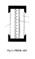
- Examples of well-known rear-projection type screens of the prior art employed in rear-projection type television sets include, as shown in figure 10, a 2-sheet type in which a Lenticular lens sheet 1 and Fresnel lens sheet 2 are combined, and as shown in figure 11, a 3-sheet-type in which a Lenticular lens sheet 1, Fresnel lens sheet 2 and front plate 3 are combined.
- these rear-projection type screens of the prior art in which 2 or more plastic lenses of different thickness and material quality are combined - gaps, which have their origin in the difference in magnitude of the elongation and shrinking of the constituent members (lens sheets or front plate) with respect to changes in temperature and humidity of the surrounds, are generated between the constituent members.
- rear-projection type screens JP-U-1-142901
- JP-U-1-142901 have been configured in which, in the manufacturing stage of the lens sheets, warp is imparted in advance by the mounting of a flat surface lens sheet in a mold and the heating thereof in this state, the elastic forces of the lens sheets are utilized to closely attach the lens sheets, and the lens sheets are fixed in the screen frame in such a way that no gaps are formed.
- a rear-projection type screen configured from two or more overlapping sheet-like members, including a fixing protrusion integrally formed in the sheet-like member in such way that neither of the two sheet-like members is displaced from the state in which the two sheet-like members overlap.
- the rear-projection type screen is configured from, by way of example, (1) two sheet-like members comprising a Lenticular lens sheet and a Fresnel lens sheet, or (2) three sheet-like members comprising a Lenticular lens sheet, a Fresnel lens sheet and front plate.
- the sheet-like members from which rear-projection screen is configured further include a protrusion which is integrally formed in the sheet-like members, used to attach the rear-projection screen to the main body of a rear-projection image display apparatus or to a screen frame.
- the above-mentioned attachment protrusion may be integrally formed independently without the provision of the above-mentioned fixing protrusion in the sheet-like member from which the rear-projection screen is configured.
- a protrusion may be integrally formed in the sheet-like member for the purpose of generating a gap between the front end section of the lens in one of the sheet-like members and the other sheet member when the two sheet-like members overlap. This gap may be of a magnitude to allow the front end section of the lens in one of the sheet-like members comes into partial contact with the other sheet-like member.
- the above-mentioned three protrusions are provided outside the effective region of the image range.
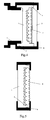
- FIG. 1 A schematic diagram of one example of a rear-projection type screen according to the present invention is shown in figure 1 and figure 2.
- the rear-projection type screen shown in figure 1 comprises a Fresnel lens sheet 1 and a Lenticular lens sheet 2, and a protrusion 4 is integrally formed in the Fresnel lens sheet 1 at the Lenticular lens sheet 2 side of a region outside the image range.
- a hollow place correspondent to the protrusion 4 is formed in the Lenticular lens sheet 2 at the Fresnel lens sheet 1 side.
- the rear-projection type screen shown in figure 2 comprises a Fresnel lens sheet 1, a Lenticular lens sheet 2 and a protrusion 4, which is integrally formed in the Fresnel lens sheet 1 at the Lenticular lens sheet 2 side of a region outside the image range, for fixing both lens sheets.
- the rear-projection type screen shown in figure 2 further comprises a protrusion 5, which is provided in the Fresnel lens sheet 1 at the rear side of region outside the image range, for fixing in a screen frame 6 and an attachment part 7 for the main body of rear-projection type image display apparatus.
- the fixing protrusion 5 may be fixed to just either the screen frame 6 or the attachment part 7 for the main body of the rear-projection type image display apparatus. It is preferable that the above-noted two protrusions 4,5 shown in figure 2 be formed of a material which is the same as the material for the main body section of the lens sheets. In the case in which different materials are employed for the protrusion and the main body section, there is a possibility that a peeling will occur at the interface of the different materials and, by the differences in thermal expansion and water absorption a waviness or wrinkles will be occurred.
- FIG. 3 and figure 4 Schematic diagrams of another example of a rear-projection type screen based on the present invention are shown in figure 3 and figure 4.
- the rear-projection type screen shown in figure 3 and figure 4 comprises a Fresnel lens sheet 1, Lenticular lens sheet 2 and front plate 3.
- a fixing protrusion 4 is integrally formed in the Fresnel lens sheet 1 in such a way that the Fresnel lens sheet 1, Lenticular lens sheet 2 and front plate 3 are not displaced.
- a fixing protrusion 4 such that the Fresnel lens sheet 1, Lenticular lens sheet 2 and front plate 3 are not displaced, and a protrusion 5, used for attachment to screen frame 6 and an attachment part 7 of the rear-projection type image display apparatus main body, are integrally formed in the Fresnel lens sheet 1.
- the whole of the Lenticular lens sheet 2 may be fitted in the Fresnel lens sheet 1 without a hollow place being used in the Lenticular lens sheet 2.
- the whole of the Lenticular lens sheet 2 may be inserted in a front plate 3 in which a protrusion 4 is provided at the both edges of the front plate 3 as shown in figure 6.
- FIG. 7 Schematic diagrams of another example of a rear-projection type screen based on the present invention are shown in figure 7 and figure 8.
- a protrusion 8 which produces a gap between the top of the lens of both lens sheets in a state in which the Fresnel lens sheet 1 and Lenticular lens sheet 2 overlap, is provided in the Fresnel lens sheet 1.
- a protrusion 8 which produces a gap between the top of the lens of the Lenticular lens sheet 2 and the front plate 3 in a state in which the Lenticular lens sheet 2 and front plate 3 overlap, is provided in the front plate 3.
- the gap be 0.1 mm or above.
- the gap be 2.0 mm or less.
- the Fresnel lens sheet can be formed by injection-molding using, for example, an acrylic resin, polycarbonate resin, a polyolefine resin, a polystylene resin, and a thermoplastic elastomer resin or a copolymer resin of these.
- the Fresnel lens sheet can be molded by a press-molding method and a photopolymerization (2P) method in which an ultraviolet cured resin is employed.
- the Lenticular lens sheet can be molded by, for example, extrusion-molding in which an acrylic resin is employed.
- the above-mentioned 3 types of protrusions can be molded by the advance-processing, in a metal mold employed in injection-molding or a stamper which is used together with the metal mold, of an inverse mold for the protrusion.
- FIG. 9 An example of an injection molder used for the molding of the Fresnel lens sheet 1 by an injection-molding method is shown in figure 9.
- a stamper 9 is attached to a fixed mirror 10 side and movable mirror 11 side.
- the stamper 9 is attached using a stamper holder 12 to the fixed mirror surface 10 side.
- the shape of the protrusion formed in the Fresnel lens sheet 1 is determined by the shape of the stamper holder 12, and the shape of the stamper holder 12 should be changed in accordance with the protrusion which is to be formed in the Fresnel lens sheet 1.
- a rear-projection type screen can be provided in which, without the need for a tape attachment operation on the outer circumferential part of the lens sheets and so on, the paring of the top of the Fresnel lens and so on due to the abrasion caused by the vibration during transportation can be prevented.
Landscapes
- Physics & Mathematics (AREA)
- General Physics & Mathematics (AREA)
- Optics & Photonics (AREA)
- Overhead Projectors And Projection Screens (AREA)
Abstract
Description
Claims (10)
- A rear-projection type screen configured from two or more overlapping sheet-like members, wherein a fixing protrusion is integrally formed in the sheet-like member in such way that neither of the two sheet-like members is displaced from the state in which the two sheet-like members overlap.
- A rear-projection type screen configured from two or more overlapping sheet-like members, wherein a protrusion, used to attach the rear-projection type screen to the main body of a rear-projection-type image display apparatus or to the screen frame, is integrally formed in the sheet-like member.
- A rear-projection type screen configured from two or more overlapping sheet-like members, wherein a protrusion, which produces a gap between the front end of a lens in one of the sheet-like members and the other sheet-like member in a state in which the two sheet-like members overlap, is integrally formed in the sheet-like member.
- A rear-projection type screen as claimed in any of claims 1 to 3, which is configured from a Lenticular lens sheet and a Fresnel lens sheet.
- A rear-projection type screen as claimed in any of claims 1 to 3, which is configured from a Lenticular lens sheet, a Fresnel lens sheet and a front plate.
- A rear-projection type screen as claimed in any of claims 1 to 5, wherein the material of the protrusion is same as that of the sheet-like member in which said protrusion is formed.
- A rear-projection type screen as claimed in any of claims 1 to 6, wherein the protrusion is formed in the sheet-like member at the region outside the image range.
- A rear-projection type screen according to claims 1, 2 or 3, which is configured from a Fresnel lens sheet having a protrusion and a Lenticular lens sheet having a hollow place which is fitted by said protrusion.
- A rear-projection type screen according to claim 8, further comprising a front plate having a hollow place which is fitted by said protrusion.
- A rear-projection type screen according to claim 2, which is configured from a Fresnel lens sheet having a first protrusion formed to fix the Fresnel lens sheet to the Lenticular lens sheet and a second protrusion formed to attach the rear-projection screen to the main body of a rear-projection type image display apparatus or to the screen frame and a Lenticular lens sheet having a hollow place which is fitted by said first protrusion.
Applications Claiming Priority (2)
| Application Number | Priority Date | Filing Date | Title |
|---|---|---|---|
| JP2000137287 | 2000-05-10 | ||
| JP2000137287A JP2001318430A (en) | 2000-05-10 | 2000-05-10 | Rear projection screen |
Publications (2)
| Publication Number | Publication Date |
|---|---|
| EP1154317A2 true EP1154317A2 (en) | 2001-11-14 |
| EP1154317A3 EP1154317A3 (en) | 2005-02-16 |
Family
ID=18645080
Family Applications (1)
| Application Number | Title | Priority Date | Filing Date |
|---|---|---|---|
| EP01111118A Withdrawn EP1154317A3 (en) | 2000-05-10 | 2001-05-08 | Rear projection screen |
Country Status (5)
| Country | Link |
|---|---|
| US (2) | US6618196B2 (en) |
| EP (1) | EP1154317A3 (en) |
| JP (1) | JP2001318430A (en) |
| KR (1) | KR20010106190A (en) |
| CN (1) | CN1191495C (en) |
Cited By (3)
| Publication number | Priority date | Publication date | Assignee | Title |
|---|---|---|---|---|
| EP1395053A1 (en) * | 2002-08-30 | 2004-03-03 | Seiko Epson Corporation | Light transmissive screen and rear projector |
| KR100740256B1 (en) * | 2005-09-08 | 2007-07-16 | (주)아이에스콤 | Screen for projector |
| US9143765B2 (en) | 2010-09-28 | 2015-09-22 | Samsung Display Co., Ltd. | Three dimensional image display |
Families Citing this family (15)
| Publication number | Priority date | Publication date | Assignee | Title |
|---|---|---|---|---|
| JP3700617B2 (en) * | 2001-07-04 | 2005-09-28 | 株式会社村田製作所 | Lens antenna |
| JP3678217B2 (en) * | 2002-07-16 | 2005-08-03 | ソニー株式会社 | Rear projection screen, rear projection screen manufacturing method, and rear projection image display apparatus |
| JP3724487B2 (en) * | 2002-12-19 | 2005-12-07 | ソニー株式会社 | Projector device |
| US7259912B2 (en) * | 2004-01-06 | 2007-08-21 | Infocus Corporation | Fresnel lens having reduced distortions |
| US7050228B2 (en) * | 2004-02-25 | 2006-05-23 | Infocus Corporation | Environmentally-adaptive frame assembly |
| CN1797054A (en) * | 2004-12-24 | 2006-07-05 | 鸿富锦精密工业(深圳)有限公司 | Portable lens die set in use for electronic equipment |
| JP2006208611A (en) * | 2005-01-26 | 2006-08-10 | Dainippon Printing Co Ltd | Translucent substrate and transmissive optical member |
| JP2006317755A (en) * | 2005-05-13 | 2006-11-24 | Mitsubishi Electric Corp | Display device, multi-screen display device, and manufacturing method of display device |
| JP4686400B2 (en) * | 2005-07-21 | 2011-05-25 | パナソニック株式会社 | Optical device, optical device apparatus, camera module, and optical device manufacturing method |
| JP2009255320A (en) * | 2008-04-14 | 2009-11-05 | Dainippon Printing Co Ltd | Identification card |
| JP4751922B2 (en) * | 2008-09-22 | 2011-08-17 | 株式会社沖データ | Lens array unit, optical head, and information device |
| US8434878B2 (en) | 2008-12-26 | 2013-05-07 | Seiko Epson Corporation | Proximity projector with a transmissive cover with modified reflectance properties |
| US9395470B2 (en) * | 2012-04-05 | 2016-07-19 | Canon Kabushiki Kaisha | Molded-article manufacturing method, mold, and optical element including fresnel lens |
| KR101985215B1 (en) * | 2015-05-29 | 2019-06-03 | 후지필름 가부시키가이샤 | Polyimide precursor composition, photosensitive resin composition, cured film, process for producing cured film, semiconductor device and process for producing polyimide precursor composition |
| CN112558399B (en) * | 2020-12-08 | 2022-03-22 | 威创集团股份有限公司 | A rear projection screen frame, a rear projection splicing wall and a method for gluing a rear projection screen frame |
Family Cites Families (16)
| Publication number | Priority date | Publication date | Assignee | Title |
|---|---|---|---|---|
| IT1137756B (en) * | 1981-07-23 | 1986-09-10 | Atb Spa | FRESNEL LENS PREFECTED AND PROCESS AND MOLD FOR OBTAINING THE SAME |
| JPH0197327A (en) | 1987-10-09 | 1989-04-14 | Hitachi Cable Ltd | Manufacturing method of twisted pair electric wire |
| JPH01142901A (en) | 1987-11-30 | 1989-06-05 | Meidensha Corp | Fuzzy inference method |
| JPH0293531A (en) | 1988-09-30 | 1990-04-04 | Dainippon Printing Co Ltd | Transparent screen |
| US4984871A (en) * | 1989-12-07 | 1991-01-15 | Eugene Martinez | Optical rear projection screen hanger assembly |
| JPH0638151A (en) * | 1992-07-14 | 1994-02-10 | Pioneer Electron Corp | Screen device for projection television receiver |
| KR0147606B1 (en) * | 1994-11-25 | 1998-09-15 | 김광호 | Projector Screen |
| JPH08211496A (en) * | 1995-02-08 | 1996-08-20 | Matsushita Electric Ind Co Ltd | Transmissive screen |
| JPH0996872A (en) * | 1995-09-28 | 1997-04-08 | Matsushita Electric Ind Co Ltd | Transmissive screen and manufacturing method thereof |
| JP3371654B2 (en) * | 1995-10-30 | 2003-01-27 | ソニー株式会社 | Projection display device |
| CN1195313A (en) * | 1996-05-10 | 1998-10-07 | 索尼株式会社 | Mold for making disc substrate, process for producing mold and disc substrate |
| JPH1197327A (en) | 1997-09-17 | 1999-04-09 | Rohm Co Ltd | Mask attaching mechanism of aligner |
| JP3587676B2 (en) * | 1998-03-23 | 2004-11-10 | 三菱電機株式会社 | Transmissive screen and projection display |
| US6407859B1 (en) * | 1999-01-13 | 2002-06-18 | 3M Innovative Properties Company | Fresnel lens for projection screen |
| US6317263B1 (en) * | 1999-06-18 | 2001-11-13 | 3M Innovative Properties Company | Projection screen using dispersing lens array for asymmetric viewing angle |
| JP3922338B2 (en) * | 2000-09-20 | 2007-05-30 | セイコーエプソン株式会社 | Substrate manufacturing method and manufacturing apparatus |
-
2000
- 2000-05-10 JP JP2000137287A patent/JP2001318430A/en active Pending
-
2001
- 2001-04-23 KR KR1020010021731A patent/KR20010106190A/en not_active Ceased
- 2001-04-30 CN CNB011174927A patent/CN1191495C/en not_active Expired - Fee Related
- 2001-05-02 US US09/846,306 patent/US6618196B2/en not_active Expired - Fee Related
- 2001-05-08 EP EP01111118A patent/EP1154317A3/en not_active Withdrawn
-
2003
- 2003-07-16 US US10/619,414 patent/US7050229B2/en not_active Expired - Fee Related
Cited By (4)
| Publication number | Priority date | Publication date | Assignee | Title |
|---|---|---|---|---|
| EP1395053A1 (en) * | 2002-08-30 | 2004-03-03 | Seiko Epson Corporation | Light transmissive screen and rear projector |
| US6947212B2 (en) | 2002-08-30 | 2005-09-20 | Seiko Epson Corporation | Transmissive screen and rear projector |
| KR100740256B1 (en) * | 2005-09-08 | 2007-07-16 | (주)아이에스콤 | Screen for projector |
| US9143765B2 (en) | 2010-09-28 | 2015-09-22 | Samsung Display Co., Ltd. | Three dimensional image display |
Also Published As
| Publication number | Publication date |
|---|---|
| EP1154317A3 (en) | 2005-02-16 |
| US20010040729A1 (en) | 2001-11-15 |
| KR20010106190A (en) | 2001-11-29 |
| CN1322964A (en) | 2001-11-21 |
| US20040085637A1 (en) | 2004-05-06 |
| US7050229B2 (en) | 2006-05-23 |
| US6618196B2 (en) | 2003-09-09 |
| JP2001318430A (en) | 2001-11-16 |
| CN1191495C (en) | 2005-03-02 |
Similar Documents
| Publication | Publication Date | Title |
|---|---|---|
| US6618196B2 (en) | Rear-projection type screen | |
| JP3587676B2 (en) | Transmissive screen and projection display | |
| EP1359463A3 (en) | Lenticular sheet, rear-projection screen or television using the same, and fabrication method for said lenticular sheet | |
| WO2003083575A1 (en) | Fresnel lens sheet | |
| JPH09133971A (en) | Rear projection TV set projection screen | |
| JP2006267778A (en) | Light diffusion sheet and transmissive screen | |
| JP4737798B2 (en) | Rear projection display | |
| JP2000292863A (en) | Transmission screen | |
| JP2873573B2 (en) | Screen plate for projection television | |
| JP3055611B2 (en) | Rear projection screen device | |
| JP3529984B2 (en) | Transmission screen | |
| JPH08129229A (en) | Plastic sheet for projection screen | |
| JP3804720B2 (en) | Projection television and screen frame | |
| JP3695302B2 (en) | Transmission screen | |
| JP2506156Y2 (en) | Screen retention structure for projection TV | |
| JP3594742B2 (en) | Extension support jig for films and sheets | |
| JPH03137625A (en) | Installation structure of projection screen | |
| JPH0915727A (en) | Transmission screen | |
| DK200200083U3 (en) | rear projection | |
| JPH05127256A (en) | Transmissive projection screen | |
| JPH05142657A (en) | Transmissive projection screen | |
| JPS6017434A (en) | Rear projection screen and its manufacturing method | |
| JP2866890B2 (en) | Projection screen | |
| JP2000347298A (en) | Rear projection screen | |
| JPH05100317A (en) | Multi-sided Fresnel lens sheet |
Legal Events
| Date | Code | Title | Description |
|---|---|---|---|
| PUAI | Public reference made under article 153(3) epc to a published international application that has entered the european phase |
Free format text: ORIGINAL CODE: 0009012 |
|
| AK | Designated contracting states |
Kind code of ref document: A2 Designated state(s): AT BE CH CY DE DK ES FI FR GB GR IE IT LI LU MC NL PT SE TR |
|
| AX | Request for extension of the european patent |
Free format text: AL;LT;LV;MK;RO;SI |
|
| PUAL | Search report despatched |
Free format text: ORIGINAL CODE: 0009013 |
|
| AK | Designated contracting states |
Kind code of ref document: A3 Designated state(s): AT BE CH CY DE DK ES FI FR GB GR IE IT LI LU MC NL PT SE TR |
|
| AX | Request for extension of the european patent |
Extension state: AL LT LV MK RO SI |
|
| 17P | Request for examination filed |
Effective date: 20050725 |
|
| AKX | Designation fees paid |
Designated state(s): DE FR GB NL |
|
| STAA | Information on the status of an ep patent application or granted ep patent |
Free format text: STATUS: THE APPLICATION IS DEEMED TO BE WITHDRAWN |
|
| 18D | Application deemed to be withdrawn |
Effective date: 20060126 |