EP1154294A1 - Optical fiber and method of manufacture thereof - Google Patents
Optical fiber and method of manufacture thereof Download PDFInfo
- Publication number
- EP1154294A1 EP1154294A1 EP99959842A EP99959842A EP1154294A1 EP 1154294 A1 EP1154294 A1 EP 1154294A1 EP 99959842 A EP99959842 A EP 99959842A EP 99959842 A EP99959842 A EP 99959842A EP 1154294 A1 EP1154294 A1 EP 1154294A1
- Authority
- EP
- European Patent Office
- Prior art keywords
- optical fiber
- core region
- refractive index
- region
- cladding
- Prior art date
- Legal status (The legal status is an assumption and is not a legal conclusion. Google has not performed a legal analysis and makes no representation as to the accuracy of the status listed.)
- Granted
Links
- 239000013307 optical fiber Substances 0.000 title claims abstract description 122
- 238000004519 manufacturing process Methods 0.000 title claims description 17
- 238000000034 method Methods 0.000 title description 17
- 238000005253 cladding Methods 0.000 claims abstract description 101
- 235000012239 silicon dioxide Nutrition 0.000 claims abstract description 65
- 230000005540 biological transmission Effects 0.000 claims abstract description 49
- ZAMOUSCENKQFHK-UHFFFAOYSA-N Chlorine atom Chemical compound [Cl] ZAMOUSCENKQFHK-UHFFFAOYSA-N 0.000 claims abstract description 37
- 229910052801 chlorine Inorganic materials 0.000 claims abstract description 37
- 239000000460 chlorine Substances 0.000 claims abstract description 37
- VYPSYNLAJGMNEJ-UHFFFAOYSA-N Silicium dioxide Chemical compound O=[Si]=O VYPSYNLAJGMNEJ-UHFFFAOYSA-N 0.000 claims abstract description 31
- 229910052731 fluorine Inorganic materials 0.000 claims abstract description 25
- 239000011737 fluorine Substances 0.000 claims abstract description 25
- 239000000377 silicon dioxide Substances 0.000 claims abstract description 3
- PXGOKWXKJXAPGV-UHFFFAOYSA-N Fluorine Chemical compound FF PXGOKWXKJXAPGV-UHFFFAOYSA-N 0.000 claims abstract 2
- 239000005373 porous glass Substances 0.000 claims description 31
- 239000006185 dispersion Substances 0.000 claims description 27
- 238000000151 deposition Methods 0.000 claims description 25
- 230000008021 deposition Effects 0.000 claims description 23
- 239000011521 glass Substances 0.000 claims description 20
- 230000018044 dehydration Effects 0.000 claims description 18
- 238000006297 dehydration reaction Methods 0.000 claims description 18
- 238000005245 sintering Methods 0.000 claims description 18
- 238000010438 heat treatment Methods 0.000 claims description 10
- 230000002093 peripheral effect Effects 0.000 claims description 8
- 238000005452 bending Methods 0.000 abstract description 42
- YCKRFDGAMUMZLT-UHFFFAOYSA-N Fluorine atom Chemical compound [F] YCKRFDGAMUMZLT-UHFFFAOYSA-N 0.000 description 23
- 239000000523 sample Substances 0.000 description 20
- 239000007789 gas Substances 0.000 description 17
- 230000000052 comparative effect Effects 0.000 description 13
- 230000003287 optical effect Effects 0.000 description 11
- 239000013067 intermediate product Substances 0.000 description 10
- 230000007423 decrease Effects 0.000 description 7
- 229910052732 germanium Inorganic materials 0.000 description 7
- GNPVGFCGXDBREM-UHFFFAOYSA-N germanium atom Chemical compound [Ge] GNPVGFCGXDBREM-UHFFFAOYSA-N 0.000 description 7
- 238000004088 simulation Methods 0.000 description 6
- 239000004071 soot Substances 0.000 description 6
- 230000000704 physical effect Effects 0.000 description 5
- 238000001947 vapour-phase growth Methods 0.000 description 5
- 229910003910 SiCl4 Inorganic materials 0.000 description 4
- 238000004891 communication Methods 0.000 description 4
- 230000000994 depressogenic effect Effects 0.000 description 4
- 239000000835 fiber Substances 0.000 description 4
- 238000005259 measurement Methods 0.000 description 4
- FDNAPBUWERUEDA-UHFFFAOYSA-N silicon tetrachloride Chemical compound Cl[Si](Cl)(Cl)Cl FDNAPBUWERUEDA-UHFFFAOYSA-N 0.000 description 4
- 229910052736 halogen Inorganic materials 0.000 description 3
- 150000002367 halogens Chemical class 0.000 description 3
- 239000000463 material Substances 0.000 description 3
- 230000001902 propagating effect Effects 0.000 description 3
- KZBUYRJDOAKODT-UHFFFAOYSA-N Chlorine Chemical compound ClCl KZBUYRJDOAKODT-UHFFFAOYSA-N 0.000 description 2
- 238000006243 chemical reaction Methods 0.000 description 2
- 230000014509 gene expression Effects 0.000 description 2
- 230000003301 hydrolyzing effect Effects 0.000 description 2
- 239000012808 vapor phase Substances 0.000 description 2
- 229910006113 GeCl4 Inorganic materials 0.000 description 1
- 229910004014 SiF4 Inorganic materials 0.000 description 1
- 239000012159 carrier gas Substances 0.000 description 1
- 239000012141 concentrate Substances 0.000 description 1
- 230000003247 decreasing effect Effects 0.000 description 1
- 239000002019 doping agent Substances 0.000 description 1
- 230000000694 effects Effects 0.000 description 1
- 230000005684 electric field Effects 0.000 description 1
- 238000011156 evaluation Methods 0.000 description 1
- 239000002737 fuel gas Substances 0.000 description 1
- 230000003252 repetitive effect Effects 0.000 description 1
- 238000012552 review Methods 0.000 description 1
- ABTOQLMXBSRXSM-UHFFFAOYSA-N silicon tetrafluoride Chemical compound F[Si](F)(F)F ABTOQLMXBSRXSM-UHFFFAOYSA-N 0.000 description 1
- IEXRMSFAVATTJX-UHFFFAOYSA-N tetrachlorogermane Chemical compound Cl[Ge](Cl)(Cl)Cl IEXRMSFAVATTJX-UHFFFAOYSA-N 0.000 description 1
Images
Classifications
-
- C—CHEMISTRY; METALLURGY
- C03—GLASS; MINERAL OR SLAG WOOL
- C03C—CHEMICAL COMPOSITION OF GLASSES, GLAZES OR VITREOUS ENAMELS; SURFACE TREATMENT OF GLASS; SURFACE TREATMENT OF FIBRES OR FILAMENTS MADE FROM GLASS, MINERALS OR SLAGS; JOINING GLASS TO GLASS OR OTHER MATERIALS
- C03C13/00—Fibre or filament compositions
- C03C13/04—Fibre optics, e.g. core and clad fibre compositions
- C03C13/045—Silica-containing oxide glass compositions
- C03C13/046—Multicomponent glass compositions
-
- C—CHEMISTRY; METALLURGY
- C03—GLASS; MINERAL OR SLAG WOOL
- C03B—MANUFACTURE, SHAPING, OR SUPPLEMENTARY PROCESSES
- C03B37/00—Manufacture or treatment of flakes, fibres, or filaments from softened glass, minerals, or slags
- C03B37/01—Manufacture of glass fibres or filaments
- C03B37/012—Manufacture of preforms for drawing fibres or filaments
- C03B37/014—Manufacture of preforms for drawing fibres or filaments made entirely or partially by chemical means, e.g. vapour phase deposition of bulk porous glass either by outside vapour deposition [OVD], or by outside vapour phase oxidation [OVPO] or by vapour axial deposition [VAD]
- C03B37/01446—Thermal after-treatment of preforms, e.g. dehydrating, consolidating, sintering
-
- C—CHEMISTRY; METALLURGY
- C03—GLASS; MINERAL OR SLAG WOOL
- C03C—CHEMICAL COMPOSITION OF GLASSES, GLAZES OR VITREOUS ENAMELS; SURFACE TREATMENT OF GLASS; SURFACE TREATMENT OF FIBRES OR FILAMENTS MADE FROM GLASS, MINERALS OR SLAGS; JOINING GLASS TO GLASS OR OTHER MATERIALS
- C03C13/00—Fibre or filament compositions
- C03C13/04—Fibre optics, e.g. core and clad fibre compositions
- C03C13/045—Silica-containing oxide glass compositions
-
- C—CHEMISTRY; METALLURGY
- C03—GLASS; MINERAL OR SLAG WOOL
- C03C—CHEMICAL COMPOSITION OF GLASSES, GLAZES OR VITREOUS ENAMELS; SURFACE TREATMENT OF GLASS; SURFACE TREATMENT OF FIBRES OR FILAMENTS MADE FROM GLASS, MINERALS OR SLAGS; JOINING GLASS TO GLASS OR OTHER MATERIALS
- C03C3/00—Glass compositions
- C03C3/04—Glass compositions containing silica
- C03C3/06—Glass compositions containing silica with more than 90% silica by weight, e.g. quartz
-
- G—PHYSICS
- G02—OPTICS
- G02B—OPTICAL ELEMENTS, SYSTEMS OR APPARATUS
- G02B6/00—Light guides; Structural details of arrangements comprising light guides and other optical elements, e.g. couplings
- G02B6/02—Optical fibres with cladding with or without a coating
- G02B6/02004—Optical fibres with cladding with or without a coating characterised by the core effective area or mode field radius
- G02B6/02009—Large effective area or mode field radius, e.g. to reduce nonlinear effects in single mode fibres
- G02B6/02014—Effective area greater than 60 square microns in the C band, i.e. 1530-1565 nm
- G02B6/02019—Effective area greater than 90 square microns in the C band, i.e. 1530-1565 nm
-
- G—PHYSICS
- G02—OPTICS
- G02B—OPTICAL ELEMENTS, SYSTEMS OR APPARATUS
- G02B6/00—Light guides; Structural details of arrangements comprising light guides and other optical elements, e.g. couplings
- G02B6/02—Optical fibres with cladding with or without a coating
- G02B6/02214—Optical fibres with cladding with or without a coating tailored to obtain the desired dispersion, e.g. dispersion shifted, dispersion flattened
- G02B6/02219—Characterised by the wavelength dispersion properties in the silica low loss window around 1550 nm, i.e. S, C, L and U bands from 1460-1675 nm
- G02B6/02252—Negative dispersion fibres at 1550 nm
- G02B6/02257—Non-zero dispersion shifted fibres, i.e. having a small negative dispersion at 1550 nm, e.g. ITU-T G.655 dispersion between - 1.0 to - 10 ps/nm.km for avoiding nonlinear effects
-
- G—PHYSICS
- G02—OPTICS
- G02B—OPTICAL ELEMENTS, SYSTEMS OR APPARATUS
- G02B6/00—Light guides; Structural details of arrangements comprising light guides and other optical elements, e.g. couplings
- G02B6/02—Optical fibres with cladding with or without a coating
- G02B6/02214—Optical fibres with cladding with or without a coating tailored to obtain the desired dispersion, e.g. dispersion shifted, dispersion flattened
- G02B6/02219—Characterised by the wavelength dispersion properties in the silica low loss window around 1550 nm, i.e. S, C, L and U bands from 1460-1675 nm
- G02B6/02266—Positive dispersion fibres at 1550 nm
-
- G—PHYSICS
- G02—OPTICS
- G02B—OPTICAL ELEMENTS, SYSTEMS OR APPARATUS
- G02B6/00—Light guides; Structural details of arrangements comprising light guides and other optical elements, e.g. couplings
- G02B6/02—Optical fibres with cladding with or without a coating
- G02B6/036—Optical fibres with cladding with or without a coating core or cladding comprising multiple layers
- G02B6/03616—Optical fibres characterised both by the number of different refractive index layers around the central core segment, i.e. around the innermost high index core layer, and their relative refractive index difference
- G02B6/03622—Optical fibres characterised both by the number of different refractive index layers around the central core segment, i.e. around the innermost high index core layer, and their relative refractive index difference having 2 layers only
- G02B6/03627—Optical fibres characterised both by the number of different refractive index layers around the central core segment, i.e. around the innermost high index core layer, and their relative refractive index difference having 2 layers only arranged - +
-
- C—CHEMISTRY; METALLURGY
- C03—GLASS; MINERAL OR SLAG WOOL
- C03B—MANUFACTURE, SHAPING, OR SUPPLEMENTARY PROCESSES
- C03B2201/00—Type of glass produced
- C03B2201/06—Doped silica-based glasses
- C03B2201/08—Doped silica-based glasses doped with boron or fluorine or other refractive index decreasing dopant
- C03B2201/12—Doped silica-based glasses doped with boron or fluorine or other refractive index decreasing dopant doped with fluorine
-
- C—CHEMISTRY; METALLURGY
- C03—GLASS; MINERAL OR SLAG WOOL
- C03B—MANUFACTURE, SHAPING, OR SUPPLEMENTARY PROCESSES
- C03B2201/00—Type of glass produced
- C03B2201/06—Doped silica-based glasses
- C03B2201/20—Doped silica-based glasses doped with non-metals other than boron or fluorine
-
- C—CHEMISTRY; METALLURGY
- C03—GLASS; MINERAL OR SLAG WOOL
- C03B—MANUFACTURE, SHAPING, OR SUPPLEMENTARY PROCESSES
- C03B2203/00—Fibre product details, e.g. structure, shape
- C03B2203/10—Internal structure or shape details
- C03B2203/22—Radial profile of refractive index, composition or softening point
-
- C—CHEMISTRY; METALLURGY
- C03—GLASS; MINERAL OR SLAG WOOL
- C03C—CHEMICAL COMPOSITION OF GLASSES, GLAZES OR VITREOUS ENAMELS; SURFACE TREATMENT OF GLASS; SURFACE TREATMENT OF FIBRES OR FILAMENTS MADE FROM GLASS, MINERALS OR SLAGS; JOINING GLASS TO GLASS OR OTHER MATERIALS
- C03C2201/00—Glass compositions
- C03C2201/06—Doped silica-based glasses
- C03C2201/08—Doped silica-based glasses containing boron or halide
- C03C2201/11—Doped silica-based glasses containing boron or halide containing chlorine
-
- C—CHEMISTRY; METALLURGY
- C03—GLASS; MINERAL OR SLAG WOOL
- C03C—CHEMICAL COMPOSITION OF GLASSES, GLAZES OR VITREOUS ENAMELS; SURFACE TREATMENT OF GLASS; SURFACE TREATMENT OF FIBRES OR FILAMENTS MADE FROM GLASS, MINERALS OR SLAGS; JOINING GLASS TO GLASS OR OTHER MATERIALS
- C03C2201/00—Glass compositions
- C03C2201/06—Doped silica-based glasses
- C03C2201/08—Doped silica-based glasses containing boron or halide
- C03C2201/12—Doped silica-based glasses containing boron or halide containing fluorine
Definitions
- the present invention relates to an optical fiber suitable for an optical transmission line in a long-haul optical communication system.
- a silica glass based fiber having a core region doped with germanium (to be referred to as a Ge-doped core optical fiber hereinafter) has been used.
- a silica glass based fiber having a core region doped with no germanium and a cladding region formed around the core region and doped with fluorine (to be referred to as a pure silica core optical fiber hereinafter) has been used.
- a silica glass based optical fiber is disclosed in Tanaka, et al., "High Silica Core Single-Mode Fibers for 1.55 ⁇ m Transmission", Fujikura Technical Review, 1990, in which the core region is doped with chlorine to reduce residual stress (to be referred to as a chlorine-doped core optical fiber hereinafter) so as to effectively suppress deformation of the refractive index profile of the optical fiber obtained after drawing.
- An optical fiber for communication is required to have a small transmission loss.
- the bending loss be small.
- the relative refractive index difference of a core region with respect to the refractive index of a cladding region must be increased to increase light confinement efficiency.
- the pure silica core optical fiber as the second prior art, a reduction in bending loss can be attained by increasing the contents of fluorine in the cladding region and increasing the relative refractive index difference between the core region composed of pure silica and the cladding region.
- the transmission loss due to Rayleigh scattering is small because the core region is composed of pure silica.
- the level of bending loss upon bending with a diameter of 20 mm needs to be 3 to 1 dB/m or less.
- Such a description states only a required value of bending loss.
- there is no description in this reference about how to realize an optical fiber that can satisfy this required value of bending loss.
- the present invention has been made to solve the above problems, and has as its object to provided an optical fiber having a structure that effectively reduces both transmission loss and bending loss, and a method of manufacturing the optical fiber.
- An optical fiber according to the present invention contains silica as a main component and includes a core region containing a predetermined amount of chlorine and a cladding region which is provided on the periphery of the core region and which contains a predetermined amount of fluorine.
- a characteristic feature of the optical fiber is that the peak value of the relative refractive index difference of the core region with respect to the refractive index of pure silica is 0.05% or more.
- the transmission loss due to Rayleigh scattering is small.
- chlorine is added as a dopant in the core region, the differences in physical property value between the core region and the cladding region decrease, and the transmission loss due to structure mismatching at the interface between the core region and the cladding region decreases.
- the peak value of the relative refractive index difference of the core region with respect to the refractive index of pure silica is 0.05% or more, the bending loss is sufficiently reduced.
- the concentration of chlorine added in the core region preferably increases from a peripheral portion of the core region toward its center.
- concentration of chlorine in a peripheral portion of the core region is lower than that in the center of the core region, the differences in physical property value between the core region and the cladding region further decrease. This further decrease the transmission loss due to structure mismatching at the interface between the core region and the cladding region.
- the chlorine added in the core region diffuses into the cladding region in the process of manufacturing the optical fiber according to the present invention, and hence chlorine is contained in at least part of the cladding region.
- an increase in transmission loss due to an OH-radical at a wavelength of 1.38 ⁇ m is 0.5 dB/km or less.
- Such a reduction in transmission loss can be attained by sufficiently performing dehydration using a halogen gas in the process of manufacturing the optical fiber. Chlorine to be contained in the core region is also introduced in this dehydration step.
- an increase in transmission loss due to an OH-radical at a wavelength of 1.38 ⁇ m exceeds 0.6 dB/km. That is, dehydration is not performed or not sufficiently performed.
- the optical fiber according to the present invention has a zero dispersion wavelength at 1.34 ⁇ m or more.
- chromatic dispersion at a wavelength of 1.55 ⁇ m is reduced. This eliminates the necessity of dispersion compensation or allows optical transmission at a wavelength of 1.55 ⁇ mwith a small amount of dispersion compensation.
- the transmission loss due to an OH-radical at a wavelength of 1.38 ⁇ m can be suppressed to 0.5 dB/km or less. This allows the use of a 1.38 ⁇ m band as a signal wavelength band.
- the diameter of the core region In order to shift the zero dispersion wavelength to a long wavelength side while the relative refractive index difference between the core region and the cladding region is maintained constant, the diameter of the core region must be decreased. If, however, the diameter of the core region decreases, the bending loss increases. The bending loss can effectively be reduced by increasing the relative refractive index difference between the core region and the cladding region. However, as the relative refractive index difference is increased by increasing the contents of germanium in the core region, the transmission loss increases. In consideration of these points, according to this optical fiber, a sufficient relative refractive index difference is obtained by adding fluorine in the cladding region without containing germanium in the core region.
- the optical fiber according to the present invention has an effective area of 100 ⁇ m 2 or more with respect to a wavelength band in use. If the effective area is 100 ⁇ m 2 or more, the non-linearity of the optical fiber is reduced. This makes it possible to effectively use this optical fiber in a case wherein a high-power optical input can be obtained as in WDM (Wavelength Division Multiplexing) transmission using an optical fiber amplifier.
- WDM Widelength Division Multiplexing
- the cladding region may have a structure including an inner cladding provided on the periphery of the core region and having an average refractive index lower than that of the core region, and an outer cladding provided on the periphery of the inner cladding and having an average refractive index lower than that of the core region but higher than that of the inner cladding.
- An optical fiber manufacturing method includes the first deposition step of obtaining a porous glass body serving as the core region, the dehydration step, and the first sintering step of making the porous glass body, obtained in the first deposition step, into a transparent glass body.
- the above porous glass body is obtained by a vapor phase deposition method such as a VAD (Vapor phase Axial Deposition) method or OVD (Outside Vapor phase Deposition) method.
- the dehydration step is performed by heating the porous glass body obtained in the first deposition step in an atmosphere containing a chlorine element. At least the concentration of chlorine in the atmosphere must be adjusted such that the peak value of the relative refractive index difference of the core region with respect to pure silica in the obtained optical fiber becomes 0.05% or more.
- This manufacturing method further includes the second deposition step of sequentially depositing one or more porous glass layers serving as a cladding region on the transparent glass body obtained in the first sintering step, and the second sintering step of making one or more porous glass layers, obtained in the second deposition step, into one or more transparent glass layers.
- dehydration may be performed by heating the glass body in an atmosphere containing chlorine between the second deposition step and the second sintering step.
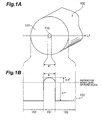
- Fig. 1A shows a sectional structure of the first embodiment (ditto for the second to fourth embodiments) of the optical fiber according to the present invention.
- Fig. 1B shows the refractive index profile of an optical fiber 100 according to the first embodiment.
- the optical fiber 100 comprises a core region 110 having a diameter a1 and extending along a predetermined axis, and a cladding region 120 provided on the periphery of the core region 110.
- the core region 110 is doped with a predetermined amount of chlorine to have a refractive index higher than that of pure silica.
- the cladding region 120 is doped with a predetermined amount of fluorine to have a refractive index lower than that of pure silica.
- the concentration of chlorine added in the core region 110 is set such that the peak value of a relative refractive index difference ⁇ n + of the core region 110 with respective to the refractive index of pure silica becomes 0.05% or more.
- the cladding region 120 has a relative refractive index difference ⁇ n - with respect to pure silica.
- the concentration of chlorine added in the core region 110 increases from a peripheral portion of the core region 110 toward the center of the core region 110.
- the abscissa of a refractive index profile 150 in Fig. 1B corresponds to the respective portions of a cross section (a surface perpendicular to the traveling direction of light signals propagating) of the optical fiber 100 according to the first embodiment (ditto for the second to fourth embodiments) in Fig. 1A on a line L1.
- a region 151 of the refractive index profile 150 corresponds to the refractive indexes of the respective portions of the core region 110 on the line L1
- a region 152 of the profile corresponds to the refractive indexes of the respective portions of the cladding region 120 on the line L1.
- a relative refractive index difference ⁇ is represented in percentage, and the refractive indexes of the respective regions in the respective definition expressions are arranged in the fixed order. When the value of ⁇ is negative, therefore, the refractive index of the corresponding region is lower than that of pure silica.
- chlorine is contained in at least part of the cladding region.
- An increase in transmission loss due to an OH-radical at a wavelength of 1.38 ⁇ m is 0.5 dB/km or less.
- a zero dispersion wavelength is set at 1.34 ⁇ m or longer. Setting a zero dispersion wavelength at 1.34 ⁇ m or longer reduces chromatic dispersion at a wavelength of 1.55 ⁇ m, and eliminates the necessity of dispersion compensation or allows optical transmission at a wavelength of 1.55 ⁇ m with a small dispersion compensation amount.
- a 1.38- ⁇ m band can be used as a signal wavelength band by setting a zero dispersion wavelength in this manner and suppressing transmission loss at a wavelength of 1.38 ⁇ m due to an OH-radical to 0.5 dB/km or less.
- the optical fiber according to the present invention has an effective area A eff of 100 ⁇ m 2 or more with respect to a wavelength band in use. If the effective area A eff is 100 ⁇ m 2 or more, non-linearity of the optical fiber is reduced. This makes it possible to effectively use this optical fiber in a case wherein a high-power optical input can be obtained as in WDM transmission using an optical fiber amplifier.
- the effective area A eff is given by where E is the electric field accompanying propagating light, and r is the distance from the center of the core in the radial direction.
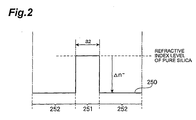
- Fig. 2 shows the refractive index profile of a pure silica core optical fiber as a comparative example.
- the pure silica core optical fiber as the comparative example has the same cross-sectional structure as that in the first embodiment shown in Fig. 1A, but differs from the first embodiment in that the core region comprised of pure silica.
- This comparative example comprises a core region having a diameter a2 and comprised of pure silica, and a cladding region provided on the periphery of the core region.
- the abscissa of a refractive index profile 250 corresponds to the respective portions on the line L1 in Fig. 1A like the refractive index profile in Fig. 1B.
- a region 251 corresponds to the refractive indexes of the respective portions on the line L1 in the core region, and a region 252 corresponds to the refractive indexes of the respective portions on a line L2 in the cladding region.
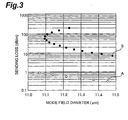
- Fig. 3 is a graph showing the result obtained by performing a simulation concerning the relationship between the mode field diameter and bending loss of each of the optical fiber 100 according to the first embodiment, which has the above structure, and the pure silica core optical fiber as a comparative example.
- White circles A plotted on Fig. 3 represent a simulation result on the optical fiber 100 according to the first embodiment, and black circles B represent a simulation result on the pure silica core optical fiber.
- the relative refractive index difference ⁇ n - of the cladding region with respect to the refractive index of pure silica is -0.3%, and each measurement value of bending loss (dB/m) is obtained at a wavelength of 1.55 ⁇ m when the fiber is bent with a diameter of 20 mm.
- the peak value of the relative refractive index difference ⁇ n + of the core region with respect to the refractive index of pure silica is 0.05%.
- the bending loss of the optical fiber 100 according to the first embodiment decreases by one or more orders of magnitudes as compared with the pure silica core optical fiber.
- the bending loss of the pure silica core optical fiber is about 20 dB/m, whereas the bending loss of the optical fiber 100 is about 0.6 dB/m.
- the first sample manufactured is the optical fiber 100 according to the first embodiment
- the second sample manufactured is the pure silica core optical fiber as a comparative example.
- the diameter a1 of the core region 110 was 11.0 ⁇ m; the peak value of the relative refractive index difference ⁇ n + of the core region 110 with respect to the refractive index of pure silica, 0.05%; the relative refractive index difference ⁇ n - of the cladding region 120 with respect to the refractive index of pure silica, - 0.3%; and the transmission loss at a wavelength of 1.55 ⁇ m, 0.175 dB/km.
- the cutoff wavelength at a length of 2 m was 1.53 ⁇ m; the mode field diameter at a wavelength of 1.55 ⁇ m, 11.2 ⁇ m; and the bending loss at a wavelength of 1.55 ⁇ m upon bending with a diameter of 20 mm, 0.5 dB/m.
- an increase in transmission loss due to an OH-radical at a wavelength of 1.38 ⁇ m was 0.3 dB/km.
- the diameter a2 of the core region was 9.2 ⁇ m; the relative refractive index difference ⁇ n - of the cladding region with respect to the refractive index of the core region (pure silica), -0.3%; the transmission loss at a wavelength of 1.55 ⁇ m, 0.176 dB/km; the cutoff wavelength at a length of 2m, 1.25 ⁇ m; the mode field diameter at a wavelength of 1.55 ⁇ m, 11.2 ⁇ m; and the bending loss at a wavelength of 1.55 ⁇ m upon bending with a diameter of 20 mm, 20.3 dB/m.
- An optical fiber 100 according to the second embodiment comprises a chlorine-doped core region 110 and a fluorine-doped cladding region 120 as in the first embodiment shown in Fig. 1A.
- the optical fiber 100 of the second embodiment therefore has a refractive index profile similar to that shown in Fig. 1B.
- a diameter a1 of the core region 110 was 13.0 ⁇ m; and the transmission loss at a wavelength of 1.55 ⁇ m, 0.171 dB/km.
- the cutoff wavelength at a length of 2 m was 1.60 ⁇ m; the mode field diameter at a wavelength of 1.55 ⁇ m, 12.1 ⁇ m; and the bending loss at a wavelength of 1.55 ⁇ m upon bending with a diameter 20 mm, 0.2 dB/m.
- an increase in transmission loss due to an OH-radical at a wavelength of 1.38 ⁇ m was 0.3 dB/km.
- a diameter a2 of the core region was 9.4 ⁇ m; the relative refractive index difference ⁇ n - of the cladding region with respect to the refractive index of the core region (pure silica); -0.25%; and the transmission loss at a wavelength of 1.55 ⁇ m, 0.170 dB/km.
- the cutoff wavelength at a length of 2 m was 1.16 ⁇ m; the mode field diameter at a wavelength of 1.55 ⁇ m, 12.1 ⁇ m; and the bending loss at a wavelength of 1.55 ⁇ m upon bending with a diameter of 20 mm, 77.5 dB/m.
- An optical fiber 100 according to the third embodiment comprises a chlorine-doped core region 110 and a fluorine-doped cladding region 120 as in the first embodiment shown in Fig. 1A.
- the optical fiber 100 of the third embodiment therefore has a refractive index profile similar to that shown in Fig. 1B.
- a diameter a1 of the core region is set to 6.8 ⁇ m to set a zero dispersion wavelength to 1.35 ⁇ m.
- the characteristics at a wavelength of 1.55 ⁇ m were: transmission loss (dB/km): :0.173 chromatic dispersion (ps/nm/km) :11.7 dispersion slope (ps/nm 2 /km) :0.052 mode field diameter ( ⁇ m) :9.29 bending loss at diameter of 20 mm (dB/m) :13.3
- the cutoff wavelength at a length of 2 m was 1.10 ⁇ m; and an increase in transmission loss due to an OH-radical at a wavelength of 1.38 ⁇ m, 0.3 dB/km.
- a dispersion slope is given as the slope of a plot representing the wavelength dependence of dispersion.
- the cladding region is doped with fluorine such that the relative refractive index difference ⁇ n - of the cladding region with respect to the refractive index of the core region (pure silica) becomes -0.35%, and a diameter a2 of the core region is set to 7.0 ⁇ m so as to set the zero dispersion wavelength to 1.35 ⁇ m.
- the characteristics at a wavelength of 1.55 ⁇ m were: transmission loss (dB/km): :0.172 chromatic dispersion (ps/nm/km) :12.5 dispersion slope (ps/nm 2 /km) :0.054 mode field diameter ( ⁇ m) :10.3 bending loss at diameter of 20 mm (dB/m) :73.5
- the cutoff wavelength at a length of 2 m was 1.00 ⁇ m.
- the optical fiber 100 according to the third embodiment can greatly reduce the bending loss while maintaining a zero dispersion wavelength and transmission characteristics such as transmission loss characteristics equivalent to those in the conventional pure silica core optical fiber.
- the fourth embodiment of the optical fiber according to the present invention also comprises a chlorine-doped core region 110 and a fluorine-doped cladding region 120 as in the first embodiment shown in Fig. 1A.
- An optical fiber 100 of the fourth embodiment therefore has a refractive index profile similar to that shown in Fig. 1B.
- a diameter a1 of the core region is set to 11.4 ⁇ m such that an effective area A eff at a wavelength of 1.55 ⁇ m becomes 103 ⁇ m 2 .
- the characteristics at a wavelength of 1.55 ⁇ m were: transmission loss (dB/km) : :0.172 chromatic dispersion (ps/nm/km) :20.5 dispersion slope (ps/nm 2 /km) :0.059 mode field diameter ( ⁇ m) : 11.4 bending loss at diameter of 20 mm (dB/m) :0.4
- the cutoff wavelength at a length of 2 m was 1.58 ⁇ m; and an increase in transmission loss due to an OH-radical at a wavelength of 1.38 ⁇ m, 0.3 dB/km.
- the cutoff wavelength at a length of 2 m is longer than the wavelength in use (1.58 ⁇ m).
- the cable cutoff wavelength (measured at a length of 22 m) defined by ITU is 1.50 ⁇ m.
- the cladding region is doped with fluorine such that the relative refractive index difference ⁇ n - of the cladding region with respect to the refractive index of the core region (pure silica) becomes -0.30%, and a diameter a2 of the core region is set to 10.2 ⁇ m such that the effective area A eff at a wavelength of 1.55 ⁇ m becomes 103 ⁇ m 2 .
- the characteristics at a wavelength of 1.55 ⁇ m were: transmission loss (dB/km): :0.172 chromatic dispersion (ps/nm/km) :19.1 dispersion slope (ps/nm 2 /km) :0.057 mode field diameter ( ⁇ m) :11.5 bending loss at diameter of 20 mm (dB/m) :6.7
- the cutoff wavelength at a length of 2 m was 1.38 ⁇ m.
- the optical fiber 100 according to the fourth embodiment can greatly reduce the bending loss while maintaining the effective area A eff and transmission characteristics such as transmission loss characteristics equivalent to those in the conventional pure silica core optical fiber.
- Each of the first to fourth embodiments described above has a matched type refractive index profile with a single cladding region.
- a depressed cladding type refractive index profile is effective in effectively suppressing an increase in bending loss and obtaining a large effective area A eff .
- An optical fiber according to the fifth embodiment therefore has a depressed cladding structure in which the above cladding is made up of an inner cladding provided on the periphery of the core region and having an average refractive index lower than that of the core region, and an outer cladding provided on the periphery of the inner cladding and having an average refractive index lower than that of the core region but higher than that of the inner cladding.
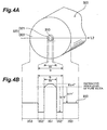
- Fig. 4A shows the cross-sectional structure of the fifth embodiment of the optical fiber according to the present invention.
- Fig. 4B shows the refractive index profile of an optical fiber 300 according to the fifth embodiment.
- the optical fiber 300 has a core region 310 having a diameter a3 and extending along a predetermined axis and a cladding region 320 provided on the periphery of the core region 310.
- the cladding region 320 comprises an inner cladding 321 provided on the periphery of the core region 310 and having an average refractive index lower than that of the core region, and an outer cladding 322 provided on the periphery of the inner cladding 321 and having an average refractive index higher than that of the inner cladding but lower than that of the core region.
- the core region 310 is doped with a predetermined amount of chlorine to have a refractive index higher than that of pure silica.
- each of the inner and outer claddings 321 and 322 is doped with a predetermined amount of fluorine to have a refractive index lower than that of pure silica.
- the concentration of chlorine added in the core region 310 is set such that the peak value of a relative refractive index difference ⁇ n + of the core region 310 with respect to the refractive index of pure silica becomes 0.05% or more.
- the inner and outer claddings respectively have a relative refractive index difference ⁇ n 2 - and a relative refractive index difference ⁇ n 1 - with respect to pure silica.
- the concentration of chlorine added in the core region 310 increases from a peripheral portion of the 310 toward the center of the core region 310.
- the abscissa of a refractive index profile 350 in Fig. 4B corresponds to the respective portions of a cross section (a surface perpendicular to the traveling direction of light signals propagating) of the optical fiber 300 according to the fifth embodiment in Fig. 4A on a line L2.
- a region 351 corresponds to the refractive indexes of the respective portions of the core region 310 on the line L2; a region 352, the refractive indexes of the respective portions of the inner cladding 321 on the line L2; and a region 353, the refractive indexes of the respective portions of the outer cladding 322 on the line L2.
- a relative refractive index difference ⁇ is represented in percentage, and the refractive indexes of the respective regions in the respective definition expressions are arranged in the fixed order. If the value of ⁇ is negative, therefore, the refractive index of the corresponding region is lower than that of pure silica.
- a diameter a3 of the core region 310 is 14.8 ⁇ m, and a diameter b of the inner cladding 321 is 59.0 ⁇ m.
- the sample of the fifth embodiment manufactured in this manner has the following characteristics at a wavelength of 1.55 ⁇ m: effective area A eff ( ⁇ m 2 ) :153 transmission loss (dB/km) :0.170 chromatic dispersion (ps/nm/km) :0.063 bending loss (dB/m) at diameter 20 mm :0.2
- the cutoff wavelength at a length of 2 m was 1.45 ⁇ m, and an increase in transmission loss due to an OH-radical at a wavelength of 1.38 ⁇ m was 0.3 dB/km.
- the use of the depressed cladding structure can greatly increase the effective area A eff while suppressing an increase in bending loss.
- the optical fiber according to the present invention can greatly reduce bending loss as compared with the pure silica core optical fiber while maintaining the same transmission loss and mode field diameter as those of the pure silica core optical fiber.
- a porous glass body 50 serving as the core region 110 is formed first by a vapor phase deposition method such as VAD (Vapor phase Axial Deposition) method or OVD (Outside Vapor phase Deposition) (the first deposition step).
- VAD Vapor phase Axial Deposition
- OVD Outside Vapor phase Deposition
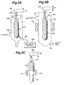
- Figs. 5A to 5C are views showing the steps to be executed until a glass preform serving as the core region 110 (310) is obtained by the above VAD method.
- Fig. 5A shows the first deposition step
- Fig. 5B the dehydration step
- Fig. 5C the first sintering step.
- the porous glass body 50 is manufactured by a soot forming device in Fig. 5A.
- This soot forming device includes a vessel 500 having at least an exhaust port 504, and a support mechanism 503 for supporting the growing porous glass body 50 (soot body).
- the support mechanism 503 has a rotatable rod 502.
- a starting rod 501 for growing the porous glass body 50 is attached to the distal end of the support rod 502.
- the soot forming device in Fig. 5A includes a burner 551 for depositing the porous glass body 50 serving as the core region 110 (310).
- a gas supply system 600 supplies a desired material gas (e.g., GeCl 4 , SiCl 4 , or the like) and fuel gases (H 2 and O 2 ), and a carrier gas such as Ar or He to the burner 551.
- a desired material gas e.g., GeCl 4 , SiCl 4 , or the like
- fuel gases H 2 and O 2
- a carrier gas such as Ar or He
- the support mechanism 503 raises the support rod 502 mounted on the distal end along the direction indicated by an arrow S2 (the longitudinal direction of the porous glass body 50) while rotating the support rod in the direction indicated by an arrow S1. With this operation, a porous glass body grows downward from the starting rod 501, thus obtaining the porous glass body 50.
- the porous glass body 50 obtained in the first deposition step described above is placed in a heating vessel 700 in Fig. 5B to undergo dehydration in an atmosphere containing a predetermined amount of chlorine.
- the heating vessel 700 has an inlet port 702 for supplying a dehydration gas and an exhaust port 701.
- the support mechanism 503 operates to move the porous glass body 50 along the direction indicated by an arrow S4 while rotating it in the direction indicated by an arrow S3 (with this operation, the entire porous glass body 50 is heated).
- a halogen gas such as SiCl 4 , other than chlorine gas, is used as a dehydration gas, a similar effect can be obtained.
- SiCl 4 in particular, can be a means of increasing the contents of chlorine and increasing the refractive index of the core region 110 (310).
- the porous glass body 50 obtained through the above process is sintered in the heating vessel 700.
- Fig. 5C shows only the main part of the heating vessel in Fig. 5B.
- the support mechanism 503 operates to move the porous glass body 50 along the direction indicated by an arrow S6 while rotating the porous glass body 50 in the direction indicated by an arrow S5. With this operation, the porous glass body 50 is transferred into a heater 750 from its leading end, and a transparent core glass preform 51 is obtained.
- the above manufacturing, dehydration, and sintering processes for the porous glass body 50 can be performed in the same vessel.
- the first deposition step is performed by the VAD method according to the above description, the first deposition step may be performed by another vapor phase deposition method such as the OVD method.
- a drawn core glass preform 52 can be obtained by drawing the core glass preform 51 obtained in the above manner to a desired diameter in a drawing step.
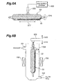
- a porous glass layer serving as the cladding region 120 (320) is deposited on the outer surface of this drawn core glass preform 52.
- a burner 900 while a burner 900 is producing a flame, glass particulates are generated by a hydrolytic reaction of a material gas supplied from the gas supply system 600 and deposited on the periphery of the outer surface of the drawn core glass preform 52. Meanwhile, the drawn core glass preform 52 moves along the direction indicated by an arrow S17 while rotating in the direction indicated by an arrow S16. With this operation, a porous glass layer (soot body) is deposited on the periphery of the outer surface of the drawn core glass preform 52 to obtain a porous intermediate product 53 (soot preform).
- the second deposition step (Fig. 6A) is performed by a required number of times while the concentration of a supplied gas is changed.
- the porous intermediate product 53 obtained through the above second deposition step is heated temporarily in an atmosphere containing a halogen gas for the purpose of dehydration to be performed before the second sintering step (see Fig. 6B). Meanwhile, the support mechanism 503 operates to move the porous intermediate product 53 along the direction indicated by an arrow S20 while rotating it in the direction indicated by an arrow S19. With this operation, the entire porous intermediate product 53 is heated. Note that Cl 2 or SiCl 4 may be used as this dehydration gas.
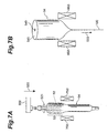
- the dehydrated porous intermediate product 53 is sintered, as shown in Fig. 7A.
- chlorine in the drawn core glass preform 52 diffuses into a peripheral glass body.
- chlorine is contained in part of the cladding region of the obtained optical fiber, and the concentration of chlorine of the core region increases from a peripheral portion of the core region to its center.
- This sintering process is continuously performed in the heating vessel 700.
- the support mechanism 503 operates to move the porous intermediate product 53 along the direction indicated by an arrow S22 while rotating it in the direction indicated by an arrow S21. With this operation, the porous intermediate product 53 is transferred into the heater 750.
- a fluorine-based gas to be supplied into the heating vessel 700 SF 6 , SiF 4 , or the like can be used.
- a porous glass layer serving as the cladding region 120 (320) is impregnated with fluorine.
- the optical fiber preform 54 can be obtained by sintering the porous intermediate product 53 upon raising the temperature in the vessel.
- the contents of fluorine is adjusted by adjusting the concentration of a fluorine-based gas supplied.
- the concentration of fluorine added can be adjusted to a desired concentration by properly adjusting the concentration of a fluorine-based gas in the process of impregnating the porous intermediate product 53 with fluorine and the sintering process.
- the deposition and sintering steps shown in Figs. 6A and 7A may be further performed. In this case, dehydration may be omitted.
- the optical fiber preform 54 obtained through the plurality of steps described above comprises a region 540 serving as a core and a region 541 serving as a cladding region after drawing.
- An end of the optical fiber preform 54 is introduced into a heater 950 and taken up while being stretched in the direction indicated by an arrow S23 in Fig. 7B, thus obtaining the optical fiber 10 (300) according to the present invention.
- the transmission loss due to Rayleigh scattering is small.
- the differences in physical property value between the core region and the cladding region decrease as the core region is doped with chlorine, and hence the transmission loss due to structural mismatching or the like at the interface between the core region and the cladding region is small.
- the peak value of the relative refractive index difference of the core region with respect to the refractive index of pure silica is 0.05% or more, the bending loss is greatly reduced.
- the concentration of chlorine added in the core region increases from a peripheral portion of the core region to its center, the differences in physical property value between the core region and the cladding region can be further reduced. This further reduce the transmission loss due to structure mismatching or the like at the interface between the core region and the cladding region.
- the above optical fiber is suited for a cable and can be suitably used as an optical transmission line in a long-haul optical communication system.
Landscapes
- Chemical & Material Sciences (AREA)
- Physics & Mathematics (AREA)
- Dispersion Chemistry (AREA)
- Optics & Photonics (AREA)
- Engineering & Computer Science (AREA)
- Materials Engineering (AREA)
- General Chemical & Material Sciences (AREA)
- Geochemistry & Mineralogy (AREA)
- Chemical Kinetics & Catalysis (AREA)
- Organic Chemistry (AREA)
- General Physics & Mathematics (AREA)
- Life Sciences & Earth Sciences (AREA)
- Thermal Sciences (AREA)
- General Life Sciences & Earth Sciences (AREA)
- Manufacturing & Machinery (AREA)
- Glass Compositions (AREA)
Abstract
Description

| transmission loss (dB/km): | :0.173 |
| chromatic dispersion (ps/nm/km) | :11.7 |
| dispersion slope (ps/nm2/km) | :0.052 |
| mode field diameter (µm) | :9.29 |
| bending loss at diameter of 20 mm (dB/m) | :13.3 |
| transmission loss (dB/km): | :0.172 |
| chromatic dispersion (ps/nm/km) | :12.5 |
| dispersion slope (ps/nm2/km) | :0.054 |
| mode field diameter (µm) | :10.3 |
| bending loss at diameter of 20 mm (dB/m) | :73.5 |
| transmission loss (dB/km) : | :0.172 |
| chromatic dispersion (ps/nm/km) | :20.5 |
| dispersion slope (ps/nm2/km) | :0.059 |
| mode field diameter (µm) | : 11.4 |
| bending loss at diameter of 20 mm (dB/m) | :0.4 |
| transmission loss (dB/km): | :0.172 |
| chromatic dispersion (ps/nm/km) | :19.1 |
| dispersion slope (ps/nm2/km) | :0.057 |
| mode field diameter (µm) | :11.5 |
| bending loss at diameter of 20 mm (dB/m) | :6.7 |
| effective area Aeff (µm2) | :153 |
| transmission loss (dB/km) | :0.170 |
| chromatic dispersion (ps/nm/km) | :0.063 |
| bending loss (dB/m) at diameter 20 mm | :0.2 |
Claims (9)
- An optical fiber mainly composed of silica and comprising:a core region extending along a predetermined axis and containing a predetermined amount of chlorine; anda cladding region provided on the outer periphery of said core region and containing a predetermined amount of fluorine,wherein a peak value of a relative refractive index difference of said core region with respect to pure silica is 0.05% or more.
- An optical fiber according to claim 1, wherein a concentration of chlorine contained in said core region increases from a peripheral portion of said core region to a center thereof.
- An optical fiber according to claim 1, wherein chlorine is contained in at least part of said cladding region.
- An optical fiber according to claim 1, wherein an increase in transmission loss due to an OH-radical at a wavelength of 1.38 µm is 0.5 dB/km or less.
- An optical fiber according to claim 1, wherein said optical fiber has a zero dispersion wavelength of 1.34 µm or longer.
- An optical fiber according to claim 1, wherein said optical fiber has an effective area of 100 µm2 or more with respect to light in a wavelength band in use.
- An optical fiber according to claim 1, wherein said cladding region comprises an inner cladding provided on the outer periphery of said core region and having an average refractive index lower than that of said core region, and an outer cladding provided on the periphery of said inner cladding and having an average refractive index lower than that of said core region but higher than that of said inner cladding.
- A method of manufacturing said optical fiber as claimed in claim 1, comprising:a first deposition step of forming a porous glass body to be served as said core region;a dehydration step of heating said porous glass body in an atmosphere containing a chlorine element to such a degree that a peak value of a relative refractive index difference of said core region with respect to pure silica becomes 0.05% or more; anda first sintering step of making said porous glass body doped with the chlorine element into a transparent glass body.
- Amethod according to claim 8, further comprising:a second deposition step of sequentially deposing one or more porous glass layers to be served as a cladding region on the outer periphery of said transparent glass body obtained in said first sintering step; anda second sintering step of making said one or more porous glass layers obtained in said second deposition step into one or more transparent glass layers.
Applications Claiming Priority (3)
| Application Number | Priority Date | Filing Date | Title |
|---|---|---|---|
| JP924499 | 1999-01-18 | ||
| JP924499 | 1999-01-18 | ||
| PCT/JP1999/007060 WO2000042458A1 (en) | 1999-01-18 | 1999-12-16 | Optical fiber and method of manufacture thereof |
Publications (3)
| Publication Number | Publication Date |
|---|---|
| EP1154294A1 true EP1154294A1 (en) | 2001-11-14 |
| EP1154294A4 EP1154294A4 (en) | 2011-04-13 |
| EP1154294B1 EP1154294B1 (en) | 2012-08-29 |
Family
ID=11715005
Family Applications (1)
| Application Number | Title | Priority Date | Filing Date |
|---|---|---|---|
| EP99959842A Expired - Lifetime EP1154294B1 (en) | 1999-01-18 | 1999-12-16 | Optical fiber and method of manufacture thereof |
Country Status (5)
| Country | Link |
|---|---|
| US (2) | US6343175B1 (en) |
| EP (1) | EP1154294B1 (en) |
| AU (1) | AU762729B2 (en) |
| TW (1) | TW425481B (en) |
| WO (1) | WO2000042458A1 (en) |
Cited By (14)
| Publication number | Priority date | Publication date | Assignee | Title |
|---|---|---|---|---|
| US6611647B2 (en) | 2000-12-12 | 2003-08-26 | Corning Incorporated | Large effective area optical fiber |
| EP1291688A3 (en) * | 2001-08-29 | 2004-05-06 | Sumitomo Electric Industries, Ltd. | Optical transmission line and optical communication system |
| EP1353202A3 (en) * | 2002-04-03 | 2004-08-18 | Samsung Electronics Co., Ltd. | Optical fibre with optimised dispersion |
| EP1438268A4 (en) * | 2001-10-26 | 2005-06-01 | Corning Inc | Methods and apparatus for forming a chlorine-doped optical waveguide preform |
| EP1500959A4 (en) * | 2002-04-30 | 2005-09-07 | Sumitomo Electric Industries | OPTICAL FIBER AND FIBER NETWORK FILTER COMPRISING SUCH A FIBER |
| EP1030200B1 (en) * | 1999-02-18 | 2008-11-19 | Draka Comteq B.V. | Optical fibre with large effective area and strong chromatic dispersion |
| CN102730961A (en) * | 2012-07-16 | 2012-10-17 | 江苏亨通光电股份有限公司 | Device and method for preparing large-size bend insensitive fiber preform |
| EP3012235A3 (en) * | 2014-10-21 | 2016-06-15 | OFS Fitel, LLC (a Delaware Limited Liability Company) | Low loss optical fiber and method of making the same |
| CN105866879A (en) * | 2016-06-14 | 2016-08-17 | 长飞光纤光缆股份有限公司 | Ultralow-attenuation large-effective-area single mode fiber |
| CN106054330A (en) * | 2015-04-01 | 2016-10-26 | 住友电气工业株式会社 | fiber optic cable |
| WO2017003982A3 (en) * | 2015-06-30 | 2017-02-23 | Corning Incorporated | Optical fiber with large effective area and low bending loss |
| US9645340B2 (en) | 2015-04-01 | 2017-05-09 | Sumitomo Electric Industries, Ltd. | Optical fiber cable |
| CN110462474A (en) * | 2017-03-27 | 2019-11-15 | 古河电气工业株式会社 | Optical fiber and method for manufacturing optical fiber |
| US11237321B2 (en) | 2014-07-10 | 2022-02-01 | Corning Incorporated | High chlorine content low attenuation optical fiber |
Families Citing this family (50)
| Publication number | Priority date | Publication date | Assignee | Title |
|---|---|---|---|---|
| US6205268B1 (en) | 1993-05-28 | 2001-03-20 | Lucent Technologies Inc. | Arrangement of optical fiber segments for minimizing effect of nonlinearities |
| WO2000042458A1 (en) * | 1999-01-18 | 2000-07-20 | Sumitomo Electric Industries, Ltd. | Optical fiber and method of manufacture thereof |
| US6556756B2 (en) * | 1999-03-17 | 2003-04-29 | Corning Incorporated | Dispersion shifted optical waveguide fiber |
| JP4080164B2 (en) * | 1999-04-13 | 2008-04-23 | 住友電気工業株式会社 | Optical fiber and optical communication system including the same |
| DE10027263B4 (en) * | 2000-05-31 | 2011-11-24 | Jenoptik Laser Gmbh | A method of making an SiO2-based optical fiber for transmitting a high power density |
| JP2002148465A (en) * | 2000-08-28 | 2002-05-22 | Sumitomo Electric Ind Ltd | Optical fiber, method for manufacturing optical fiber preform, and method for manufacturing optical fiber |
| AU773229B2 (en) * | 2000-08-28 | 2004-05-20 | Sumitomo Electric Industries, Ltd. | Optical fiber and method of making the same |
| JP2002148466A (en) * | 2000-08-28 | 2002-05-22 | Sumitomo Electric Ind Ltd | Optical fiber and method for manufacturing the same |
| JP3764040B2 (en) * | 2000-10-03 | 2006-04-05 | 株式会社フジクラ | Optical fiber |
| JP2002202428A (en) * | 2000-10-31 | 2002-07-19 | Sumitomo Electric Ind Ltd | Optical fiber |
| TWI226464B (en) * | 2000-11-13 | 2005-01-11 | Sumitomo Electric Industries | Optical fiber, non-linear optical fiber, optical amplifier using the same optical fiber, wavelength converter and optical fiber manufacture method |
| JP2003084163A (en) * | 2001-09-07 | 2003-03-19 | Sumitomo Electric Ind Ltd | Optical fiber, optical transmission line and optical communication system |
| CN1310045C (en) * | 2002-10-01 | 2007-04-11 | 古河电气工业株式会社 | Optical fiber, optical transmission line and method for manufacturing optical fiber |
| US6826341B2 (en) * | 2002-11-04 | 2004-11-30 | Fitel Usa Corp. | Systems and methods for reducing splice loss in optical fibers |
| US6901197B2 (en) * | 2003-01-13 | 2005-05-31 | Sumitomo Electric Industries, Ltd. | Microstructured optical fiber |
| JP5176274B2 (en) * | 2003-05-19 | 2013-04-03 | 住友電気工業株式会社 | Optical fiber and manufacturing method thereof |
| US6917740B2 (en) * | 2003-05-30 | 2005-07-12 | Corning Incorporated | Optical fiber having reduced viscosity mismatch |
| WO2005012967A1 (en) | 2003-08-04 | 2005-02-10 | Sumitomo Electric Industries, Ltd. | Fiber optics |
| JP2007504080A (en) | 2003-08-29 | 2007-03-01 | コーニング インコーポレイテッド | Optical fiber containing alkali metal oxide and method and apparatus for manufacturing the same |
| EP1547981A3 (en) * | 2003-12-25 | 2011-07-06 | Sumitomo Electric Industries, Ltd. | Method of manufacturing fluorine doped silica glass article, preform and optical fiber and optical fiber made by the method |
| KR100693638B1 (en) | 2004-04-28 | 2007-03-14 | 엘에스전선 주식회사 | Bending Robust Fiber Optics |
| CN100476469C (en) * | 2004-04-28 | 2009-04-08 | Ls电线有限公司 | Optical fiber with improved bending performance |
| US7187833B2 (en) * | 2004-04-29 | 2007-03-06 | Corning Incorporated | Low attenuation large effective area optical fiber |
| US20060037039A1 (en) * | 2004-08-13 | 2006-02-16 | Nokia Corporation | Delivering data to radio or television during commercials |
| US7336877B2 (en) * | 2004-08-31 | 2008-02-26 | Corning Incorporated | Broadband optical fiber |
| US7272289B2 (en) * | 2005-09-30 | 2007-09-18 | Corning Incorporated | Low bend loss optical fiber |
| US11324553B2 (en) * | 2005-11-10 | 2022-05-10 | Biolitec Unternehmensbeteilgungs II AG | Side fire optical fiber for high power applications |
| CN101583891A (en) * | 2005-11-23 | 2009-11-18 | 康宁股份有限公司 | Low attenuation non-zero dispersion shifted optical fiber |
| CN101046873A (en) * | 2006-03-29 | 2007-10-03 | 腾讯科技(深圳)有限公司 | Method and device for issuing network advertisement in network game |
| EP2120073B1 (en) | 2007-03-05 | 2011-09-28 | Fujikura, Ltd. | Photonic band gap fiber |
| JP4452756B2 (en) | 2007-03-05 | 2010-04-21 | 株式会社フジクラ | Photonic bandgap fiber |
| US7805039B2 (en) * | 2007-05-04 | 2010-09-28 | Weatherford/Lamb, Inc. | Single mode optical fiber with improved bend performance |
| JP5307114B2 (en) | 2008-02-29 | 2013-10-02 | 古河電気工業株式会社 | Optical fiber |
| CN101373238B (en) * | 2008-08-20 | 2010-09-08 | 富通集团有限公司 | Bending Loss Insensitive Single Mode Fiber |
| JP2010064915A (en) | 2008-09-09 | 2010-03-25 | Shin-Etsu Chemical Co Ltd | Method for producing optical fiber preform |
| US8315495B2 (en) * | 2009-01-30 | 2012-11-20 | Corning Incorporated | Large effective area fiber with Ge-free core |
| US7689085B1 (en) | 2009-01-30 | 2010-03-30 | Corning Incorporated | Large effective area fiber with GE-free core |
| CN101598834B (en) * | 2009-06-26 | 2011-01-19 | 长飞光纤光缆有限公司 | A kind of single-mode optical fiber and its manufacturing method |
| JP2011039109A (en) * | 2009-08-06 | 2011-02-24 | Sumitomo Electric Ind Ltd | Optical communication system |
| CN102156323B (en) | 2011-05-05 | 2012-06-06 | 长飞光纤光缆有限公司 | Single mode fiber |
| US8565567B2 (en) * | 2011-11-23 | 2013-10-22 | Sumitomo Electric Industries, Ltd. | Multi-mode optical fiber |
| JP6268758B2 (en) * | 2013-06-10 | 2018-01-31 | 住友電気工業株式会社 | Optical fiber |
| JP2017024917A (en) * | 2015-07-15 | 2017-02-02 | 株式会社フジクラ | Optical fiber preform, optical fiber, and optical fiber manufacturing method |
| CN107357004B (en) * | 2017-07-04 | 2020-04-21 | 长飞光纤光缆股份有限公司 | Low-attenuation single-mode optical fiber and preparation method thereof |
| US10947149B2 (en) * | 2017-10-30 | 2021-03-16 | Corning Incorporated | Halogen-doped silica for optical fiber preforms |
| JP7608438B2 (en) | 2020-03-27 | 2025-01-06 | 古河電気工業株式会社 | Optical Fiber |
| CN111781673B (en) * | 2020-07-08 | 2022-06-28 | 普天线缆集团有限公司 | Novel ultra-low loss G.654E optical fiber and method of making the same |
| JPWO2022215603A1 (en) * | 2021-04-08 | 2022-10-13 | ||
| CN118202282A (en) * | 2021-07-26 | 2024-06-14 | Ofs菲特尔有限责任公司 | Optical fiber including a triangular groove profile |
| CN113461322B (en) * | 2021-07-30 | 2023-05-09 | 浙江富通光纤技术有限公司 | Optical fiber and method for manufacturing optical fiber preform |
Family Cites Families (26)
| Publication number | Priority date | Publication date | Assignee | Title |
|---|---|---|---|---|
| US4372647A (en) * | 1979-10-08 | 1983-02-08 | Nippon Telegraph & Telephone Public Corporation | Single mode optical fibers |
| US4435040A (en) * | 1981-09-03 | 1984-03-06 | Bell Telephone Laboratories, Incorporated | Double-clad optical fiberguide |
| JPS6140843A (en) * | 1984-07-31 | 1986-02-27 | Furukawa Electric Co Ltd:The | Optical fiber |
| DE181595T1 (en) * | 1984-11-15 | 1986-09-04 | Polaroid Corp., Cambridge, Mass. | DIELECTRIC WAVE GUIDE WITH CHLORINE DOPING. |
| JPH0776104B2 (en) | 1985-07-08 | 1995-08-16 | 住友電気工業株式会社 | Method of manufacturing constant polarization optical fiber |
| JPS62176941A (en) * | 1986-01-28 | 1987-08-03 | Sumitomo Electric Ind Ltd | Optical fiber |
| JPH0742130B2 (en) | 1986-07-07 | 1995-05-10 | 古河電気工業株式会社 | Method for manufacturing rod-shaped base material for optical transmission line |
| JPS63182233A (en) | 1987-01-21 | 1988-07-27 | Hitachi Cable Ltd | Manufacturing method of optical fiber base material |
| JPH0196039A (en) * | 1987-10-07 | 1989-04-14 | Sumitomo Electric Ind Ltd | Production of optical fiber preform |
| JPH03218947A (en) * | 1990-01-23 | 1991-09-26 | Shin Etsu Chem Co Ltd | Rare-earth element and halogen element-doped quartz glass-based optical fiber preform and its production |
| JP3106564B2 (en) | 1991-07-24 | 2000-11-06 | 住友電気工業株式会社 | Manufacturing method of optical fiber and silica-based optical fiber |
| JPH06171978A (en) | 1992-12-04 | 1994-06-21 | Furukawa Electric Co Ltd:The | Quartz optical fiber |
| US5397372A (en) * | 1993-11-30 | 1995-03-14 | At&T Corp. | MCVD method of making a low OH fiber preform with a hydrogen-free heat source |
| US5835655A (en) | 1995-01-26 | 1998-11-10 | Corning Incorporated | Large effective area waveguide fiber |
| JP3218947B2 (en) | 1995-10-27 | 2001-10-15 | 株式会社神戸製鋼所 | Manufacturing method of oxide superconducting wire |
| UA42008C2 (en) * | 1996-02-12 | 2001-10-15 | Корнінг Інкорпорейтид | Single-mode optical fiber (versions) |
| JP3675579B2 (en) * | 1996-08-08 | 2005-07-27 | 住友電気工業株式会社 | Manufacturing method of optical fiber preform |
| JP3845906B2 (en) | 1996-08-09 | 2006-11-15 | 住友電気工業株式会社 | Method for producing synthetic silica glass |
| JP3300233B2 (en) * | 1996-09-12 | 2002-07-08 | 昭和電線電纜株式会社 | Optical fiber |
| US5781684A (en) * | 1996-12-20 | 1998-07-14 | Corning Incorporated | Single mode optical waveguide having large effective area |
| JPH10206654A (en) | 1997-01-16 | 1998-08-07 | Sumitomo Electric Ind Ltd | Optical fiber and method for manufacturing the same |
| JP3738510B2 (en) | 1997-01-16 | 2006-01-25 | 住友電気工業株式会社 | Optical fiber and manufacturing method thereof |
| JP3337954B2 (en) * | 1997-09-17 | 2002-10-28 | 株式会社フジクラ | Dispersion compensating optical fiber |
| JP3928355B2 (en) * | 1998-11-26 | 2007-06-13 | 住友電気工業株式会社 | Optical fiber and optical transmission system including the same |
| WO2000042458A1 (en) * | 1999-01-18 | 2000-07-20 | Sumitomo Electric Industries, Ltd. | Optical fiber and method of manufacture thereof |
| JP4080164B2 (en) * | 1999-04-13 | 2008-04-23 | 住友電気工業株式会社 | Optical fiber and optical communication system including the same |
-
1999
- 1999-12-16 WO PCT/JP1999/007060 patent/WO2000042458A1/en not_active Ceased
- 1999-12-16 EP EP99959842A patent/EP1154294B1/en not_active Expired - Lifetime
- 1999-12-16 AU AU16870/00A patent/AU762729B2/en not_active Ceased
-
2000
- 2000-01-13 TW TW089100468A patent/TW425481B/en not_active IP Right Cessation
- 2000-07-12 US US09/615,072 patent/US6343175B1/en not_active Expired - Lifetime
-
2002
- 2002-01-22 US US10/051,143 patent/US6449415B1/en not_active Expired - Lifetime
Cited By (26)
| Publication number | Priority date | Publication date | Assignee | Title |
|---|---|---|---|---|
| EP1030200B1 (en) * | 1999-02-18 | 2008-11-19 | Draka Comteq B.V. | Optical fibre with large effective area and strong chromatic dispersion |
| US6611647B2 (en) | 2000-12-12 | 2003-08-26 | Corning Incorporated | Large effective area optical fiber |
| EP1291688A3 (en) * | 2001-08-29 | 2004-05-06 | Sumitomo Electric Industries, Ltd. | Optical transmission line and optical communication system |
| EP1438268A4 (en) * | 2001-10-26 | 2005-06-01 | Corning Inc | Methods and apparatus for forming a chlorine-doped optical waveguide preform |
| EP1353202A3 (en) * | 2002-04-03 | 2004-08-18 | Samsung Electronics Co., Ltd. | Optical fibre with optimised dispersion |
| US6999667B2 (en) | 2002-04-03 | 2006-02-14 | Samsung Electronics Co., Ltd. | Dispersion-controlled optical fiber |
| US7203399B2 (en) | 2002-04-30 | 2007-04-10 | Sumitomo Electric Industries, Ltd. | Optical fiber and fiber grating type filter including the same |
| EP1500959A4 (en) * | 2002-04-30 | 2005-09-07 | Sumitomo Electric Industries | OPTICAL FIBER AND FIBER NETWORK FILTER COMPRISING SUCH A FIBER |
| CN102730961A (en) * | 2012-07-16 | 2012-10-17 | 江苏亨通光电股份有限公司 | Device and method for preparing large-size bend insensitive fiber preform |
| CN102730961B (en) * | 2012-07-16 | 2015-01-14 | 江苏亨通光电股份有限公司 | Device and method for preparing large-size bend insensitive fiber preform |
| US11237321B2 (en) | 2014-07-10 | 2022-02-01 | Corning Incorporated | High chlorine content low attenuation optical fiber |
| US9658395B2 (en) | 2014-10-21 | 2017-05-23 | Ofs Fitel, Llc | Low loss optical fiber and method of making the same |
| EP3012235A3 (en) * | 2014-10-21 | 2016-06-15 | OFS Fitel, LLC (a Delaware Limited Liability Company) | Low loss optical fiber and method of making the same |
| US10197728B2 (en) | 2014-10-21 | 2019-02-05 | Ofs Fitel, Llc | Low loss optical fiber and method of making the same |
| CN106054330A (en) * | 2015-04-01 | 2016-10-26 | 住友电气工业株式会社 | fiber optic cable |
| US9645340B2 (en) | 2015-04-01 | 2017-05-09 | Sumitomo Electric Industries, Ltd. | Optical fiber cable |
| US9696508B2 (en) | 2015-04-01 | 2017-07-04 | Sumitomo Electric Industries, Ltd. | Optical fiber cable |
| EP3088930A1 (en) * | 2015-04-01 | 2016-11-02 | Sumitomo Electric Industries, Ltd. | Optical fiber cable |
| CN106054330B (en) * | 2015-04-01 | 2019-10-22 | 住友电气工业株式会社 | fiber optic cable |
| WO2017003982A3 (en) * | 2015-06-30 | 2017-02-23 | Corning Incorporated | Optical fiber with large effective area and low bending loss |
| US9851499B2 (en) | 2015-06-30 | 2017-12-26 | Corning Incorporated | Optical fiber with large effective area and low bending loss |
| CN107850728A (en) * | 2015-06-30 | 2018-03-27 | 康宁股份有限公司 | Optical fiber with large effective area and low bend loss |
| CN107850728B (en) * | 2015-06-30 | 2020-07-28 | 康宁股份有限公司 | Fibers with large effective area and low bending loss |
| CN105866879A (en) * | 2016-06-14 | 2016-08-17 | 长飞光纤光缆股份有限公司 | Ultralow-attenuation large-effective-area single mode fiber |
| CN110462474A (en) * | 2017-03-27 | 2019-11-15 | 古河电气工业株式会社 | Optical fiber and method for manufacturing optical fiber |
| US11079537B2 (en) | 2017-03-27 | 2021-08-03 | Furukawa Electric Co., Ltd. | Optical fiber and manufacturing method of optical fiber |
Also Published As
| Publication number | Publication date |
|---|---|
| WO2000042458A1 (en) | 2000-07-20 |
| EP1154294B1 (en) | 2012-08-29 |
| AU762729B2 (en) | 2003-07-03 |
| US6449415B1 (en) | 2002-09-10 |
| EP1154294A4 (en) | 2011-04-13 |
| US20020097970A1 (en) | 2002-07-25 |
| AU1687000A (en) | 2000-08-01 |
| US6343175B1 (en) | 2002-01-29 |
| TW425481B (en) | 2001-03-11 |
Similar Documents
| Publication | Publication Date | Title |
|---|---|---|
| EP1154294B1 (en) | Optical fiber and method of manufacture thereof | |
| EP1813581B1 (en) | Method for manufacturing an optical fiber preform, optical fiber preform and optical fiber | |
| US5995695A (en) | Dispersion compensating optical fiber | |
| EP1740986B1 (en) | Low attenuation large effective area optical fiber | |
| US7095940B2 (en) | Optical fiber, method for manufacturing same and optical transmission channel | |
| EP1488261B1 (en) | Low bend loss optical fiber and components made therefrom | |
| US6535679B2 (en) | Optical fiber and method of manufacturing the same | |
| US20030063878A1 (en) | Optical fiber, optical fiber preform, and method for manufacturing optical fiber preform | |
| CN111308609B (en) | Large-effective-area low-loss single-mode optical fiber | |
| CA2565879C (en) | Long wavelength, pure silica core single mode fiber and method of forming the same | |
| US6925239B2 (en) | High performance dispersion compensating optical fibers and manufacturing method for the same | |
| JP2005534963A (en) | Non-zero dispersion shifted optical fiber with large effective area, low tilt and low zero dispersion | |
| US20170219770A1 (en) | Low attenuation fiber with viscosity matched core and inner clad | |
| AU719695B2 (en) | Optical fiber and method of manufacturing the same | |
| CN111239891B (en) | Low-loss cut-off wavelength displacement single-mode fiber | |
| JP2006512615A (en) | Dispersion flat NZDS fiber | |
| JP2007536580A5 (en) | ||
| EP1195628A1 (en) | Optical fibre with improved hydrogen resistance | |
| US6904213B2 (en) | Step index optical fiber with doped cladding and core, a preform, and a method of fabricating such a fiber | |
| US5683486A (en) | Method of forming a fiber preform to minimize shifts of the zero-dispersion wavelength | |
| KR102944739B1 (en) | Optical fiber | |
| CN114195379A (en) | Drawing method of low-loss cut-off wavelength displacement single-mode optical fiber | |
| AU2003203793B2 (en) | Optical fiber and method of manufacture thereof | |
| KR101627830B1 (en) | A non-zero dispersion shifted optical fiber and optical transmission line using the same, and optical transmission system | |
| JPWO2000042458A1 (en) | Optical fiber and its manufacturing method |
Legal Events
| Date | Code | Title | Description |
|---|---|---|---|
| PUAI | Public reference made under article 153(3) epc to a published international application that has entered the european phase |
Free format text: ORIGINAL CODE: 0009012 |
|
| 17P | Request for examination filed |
Effective date: 20010808 |
|
| AK | Designated contracting states |
Kind code of ref document: A1 Designated state(s): AT BE CH CY DE DK ES FI FR GB GR IE IT LI LU MC NL PT SE |
|
| RBV | Designated contracting states (corrected) |
Designated state(s): DE FR IT |
|
| A4 | Supplementary search report drawn up and despatched |
Effective date: 20110311 |
|
| 17Q | First examination report despatched |
Effective date: 20110803 |
|
| GRAP | Despatch of communication of intention to grant a patent |
Free format text: ORIGINAL CODE: EPIDOSNIGR1 |
|
| REG | Reference to a national code |
Ref country code: DE Ref legal event code: R079 Ref document number: 69944378 Country of ref document: DE Free format text: PREVIOUS MAIN CLASS: G02B0006160000 Ipc: G02B0006000000 |
|
| RIC1 | Information provided on ipc code assigned before grant |
Ipc: C03B 37/018 20060101ALI20120316BHEP Ipc: G02B 6/00 20060101AFI20120316BHEP |
|
| RIN1 | Information on inventor provided before grant (corrected) |
Inventor name: SASAOKA, EISUKE, |
|
| GRAS | Grant fee paid |
Free format text: ORIGINAL CODE: EPIDOSNIGR3 |
|
| GRAA | (expected) grant |
Free format text: ORIGINAL CODE: 0009210 |
|
| AK | Designated contracting states |
Kind code of ref document: B1 Designated state(s): DE FR IT |
|
| REG | Reference to a national code |
Ref country code: DE Ref legal event code: R096 Ref document number: 69944378 Country of ref document: DE Effective date: 20121025 |
|
| PLBE | No opposition filed within time limit |
Free format text: ORIGINAL CODE: 0009261 |
|
| STAA | Information on the status of an ep patent application or granted ep patent |
Free format text: STATUS: NO OPPOSITION FILED WITHIN TIME LIMIT |
|
| 26N | No opposition filed |
Effective date: 20130530 |
|
| REG | Reference to a national code |
Ref country code: DE Ref legal event code: R097 Ref document number: 69944378 Country of ref document: DE Effective date: 20130530 |
|
| REG | Reference to a national code |
Ref country code: FR Ref legal event code: PLFP Year of fee payment: 17 |
|
| REG | Reference to a national code |
Ref country code: FR Ref legal event code: PLFP Year of fee payment: 18 |
|
| REG | Reference to a national code |
Ref country code: FR Ref legal event code: PLFP Year of fee payment: 19 |
|
| PGFP | Annual fee paid to national office [announced via postgrant information from national office to epo] |
Ref country code: DE Payment date: 20181204 Year of fee payment: 20 |
|
| PGFP | Annual fee paid to national office [announced via postgrant information from national office to epo] |
Ref country code: FR Payment date: 20181122 Year of fee payment: 20 |
|
| PGFP | Annual fee paid to national office [announced via postgrant information from national office to epo] |
Ref country code: IT Payment date: 20181220 Year of fee payment: 20 |
|
| REG | Reference to a national code |
Ref country code: DE Ref legal event code: R071 Ref document number: 69944378 Country of ref document: DE |