EP1154246A2 - Füllstandsanzeige mit Lichtquelle - Google Patents
Füllstandsanzeige mit Lichtquelle Download PDFInfo
- Publication number
- EP1154246A2 EP1154246A2 EP01110683A EP01110683A EP1154246A2 EP 1154246 A2 EP1154246 A2 EP 1154246A2 EP 01110683 A EP01110683 A EP 01110683A EP 01110683 A EP01110683 A EP 01110683A EP 1154246 A2 EP1154246 A2 EP 1154246A2
- Authority
- EP
- European Patent Office
- Prior art keywords
- light
- level indicator
- light guide
- indicator according
- display means
- Prior art date
- Legal status (The legal status is an assumption and is not a legal conclusion. Google has not performed a legal analysis and makes no representation as to the accuracy of the status listed.)
- Withdrawn
Links
Images

Classifications
-
- G—PHYSICS
- G01—MEASURING; TESTING
- G01F—MEASURING VOLUME, VOLUME FLOW, MASS FLOW OR LIQUID LEVEL; METERING BY VOLUME
- G01F23/00—Indicating or measuring liquid level or level of fluent solid material, e.g. indicating in terms of volume or indicating by means of an alarm
- G01F23/02—Indicating or measuring liquid level or level of fluent solid material, e.g. indicating in terms of volume or indicating by means of an alarm by gauge glasses or other apparatus involving a window or transparent tube for directly observing the level to be measured or the level of a liquid column in free communication with the main body of the liquid
-
- G—PHYSICS
- G01—MEASURING; TESTING
- G01F—MEASURING VOLUME, VOLUME FLOW, MASS FLOW OR LIQUID LEVEL; METERING BY VOLUME
- G01F23/00—Indicating or measuring liquid level or level of fluent solid material, e.g. indicating in terms of volume or indicating by means of an alarm
- G01F23/22—Indicating or measuring liquid level or level of fluent solid material, e.g. indicating in terms of volume or indicating by means of an alarm by measuring physical variables, other than linear dimensions, pressure or weight, dependent on the level to be measured, e.g. by difference of heat transfer of steam or water
- G01F23/28—Indicating or measuring liquid level or level of fluent solid material, e.g. indicating in terms of volume or indicating by means of an alarm by measuring physical variables, other than linear dimensions, pressure or weight, dependent on the level to be measured, e.g. by difference of heat transfer of steam or water by measuring the variations of parameters of electromagnetic or acoustic waves applied directly to the liquid or fluent solid material
- G01F23/284—Electromagnetic waves
- G01F23/292—Light, e.g. infrared or ultraviolet
- G01F23/2921—Light, e.g. infrared or ultraviolet for discrete levels
- G01F23/2922—Light, e.g. infrared or ultraviolet for discrete levels with light-conducting sensing elements, e.g. prisms
- G01F23/2924—Light, e.g. infrared or ultraviolet for discrete levels with light-conducting sensing elements, e.g. prisms for several discrete levels, e.g. with more than one light-conducting sensing element
-
- G—PHYSICS
- G01—MEASURING; TESTING
- G01F—MEASURING VOLUME, VOLUME FLOW, MASS FLOW OR LIQUID LEVEL; METERING BY VOLUME
- G01F23/00—Indicating or measuring liquid level or level of fluent solid material, e.g. indicating in terms of volume or indicating by means of an alarm
- G01F23/30—Indicating or measuring liquid level or level of fluent solid material, e.g. indicating in terms of volume or indicating by means of an alarm by floats
- G01F23/64—Indicating or measuring liquid level or level of fluent solid material, e.g. indicating in terms of volume or indicating by means of an alarm by floats of the free float type without mechanical transmission elements
-
- G—PHYSICS
- G01—MEASURING; TESTING
- G01F—MEASURING VOLUME, VOLUME FLOW, MASS FLOW OR LIQUID LEVEL; METERING BY VOLUME
- G01F23/00—Indicating or measuring liquid level or level of fluent solid material, e.g. indicating in terms of volume or indicating by means of an alarm
- G01F23/30—Indicating or measuring liquid level or level of fluent solid material, e.g. indicating in terms of volume or indicating by means of an alarm by floats
- G01F23/64—Indicating or measuring liquid level or level of fluent solid material, e.g. indicating in terms of volume or indicating by means of an alarm by floats of the free float type without mechanical transmission elements
- G01F23/68—Indicating or measuring liquid level or level of fluent solid material, e.g. indicating in terms of volume or indicating by means of an alarm by floats of the free float type without mechanical transmission elements using electrically actuated indicating means
- G01F23/686—Indicating or measuring liquid level or level of fluent solid material, e.g. indicating in terms of volume or indicating by means of an alarm by floats of the free float type without mechanical transmission elements using electrically actuated indicating means using opto-electrically actuated indicating means
Definitions
- the invention relates to a level indicator, according to the preamble of claim 1.
- Level indicators are used, for example, in kettles or coffee machines used to visually check the fill level of a liquid container to be able to control.
- DE-OS 20 38 850 is a cover glass for a liquid level indicator known, in the form of a translucent sight glass for observing a Level of a container is formed.
- the liquid level indicator is as Reflection indicator formed on the one facing the medium to be measured Side has grooves. In the steam or gas-filled area of the sight glass, this becomes incident light reflected on the grooves. The grooves therefore appear in this area silvery or white. In the liquid-filled area, however, the incident light due to the higher refractive index of the liquid in the Liquid space broke in and partially absorbed there. This area appears dark. In this way the interface between liquid and vapor is relatively good recognizable.
- the object of the invention is to make the interface between to improve a first and a second medium in a level indicator.
- An advantage The invention is that to improve the visibility of the interface a light source is provided which the display means in addition to the natural light supplied with light. In this way, the optical effect on the interface occurs, intensified.
- An advantageous embodiment of the invention is provided with a Display means achieved, which is in the form of a tube with an inner channel.
- the light source is coupled to the inner channel.
- the Pipe By the Pipe, the light energy introduced by the light source is guided in the inner channel, see above that a high light energy is available at the interface, which the optical Effect intensified.
- a further enhancement of the optical effect is preferably by use reached a float, which is arranged in the inner channel.
- the floating body is illuminated by the light source and is clearly recognizable as an interface.
- a preferred embodiment of the float is the To form translucent floats on the top and bottom, the Float is also built in such a way that from the top or bottom light is emitted laterally to the outside. That way it will Light emitted by the light source is laterally reflected in the direction of an observer.
- the floating body Floating bodies at least partially constructed from a light-collecting material.
- the float thus provides an interface for that from the light source emitted light, so that the light beam in the inner channel abruptly on the float ends and is therefore clearly recognizable as an interface.
- Another preferred embodiment consists in the use of an optical fiber, whose outer surface is constructed in such a way that a different Refractive index exists in the transition between liquid and air. In this way becomes the light guided in the light guide in the area in which liquid is on the light guide is reflected differently to the outside than in the area where there is no liquid is present. The interface between liquid and air is clearly visible.
- a preferred embodiment of the light guide is the surface of the Light guide with a coating, depending on whether liquid or air, has a different refractive index and therefore also Emits light differently to the outside.
- the Surface of the light guide has mechanical structures which, depending on whether liquid or air is adjacent, a different reflection behavior at the Has inside of the light guide. In this way, in the area of the liquid led light in the light guide with different efficiency, so that from Outside there is a difference in brightness between the area where liquid is at Light guide adjoins and the area in which air adjoins the light guide can be seen.
- the liquid container 1 schematically shows a liquid container 1.
- the liquid container 1 can for example, be installed in a coffee machine or a water heater.
- a tube 3 is arranged, which from a bottom surface 13 to the upper edge of the liquid container 1 is guided.
- the tube 3 consists of a transparent, translucent material.
- the tube 3 has openings 4 in the area of the bottom surface 13, via which the liquid in can tile an inner channel 12.
- the tube 3 is essentially cylindrical Sleeve constructed with an inner channel 12.
- the cross section of the tube 3 is in the The illustrated embodiment is cylindrical, but depending on the embodiment also be rectangular or have other cross sections.
- the tube 3 is for example made of clear plexiglass or plastic.
- a light source 2 is either in the region of the Bottom surface 13 arranged in the tube 3 or at least in the area of the bottom surface 13 the inner channel 12 optically coupled.
- the light source 2 can also be located away from the tube 3 and optically to the coupling lines Inner channel 12 can be coupled.
- the light source 2 has electrical lines 6 that lead to a power supply.
- the light source 2 is, for example, a light emitting diode or glow lamp.
- the light source 2 is arranged in such a way that the light emitted by the light source 2 is radiated upward in the inner channel 12.
- the Light emitted by the light source 2 is emitted by the liquid that is in the inner channel 12 is led upwards.
- the tube 3 limits the light in the spread and leads the light in the inner channel 12 upwards. At the interface between liquid and Air is a part of the light guided in the inner channel 12 laterally reflected outwards, so that an optical effect occurs in the area of the interface, which is from the outside Sight glass 17 is clearly visible.
- the sight glass 17 is in the area of the tube 3 in the Wall of the liquid container 1 introduced.
- a floating body 5 in the inner channel 12 which floats on the liquid 11.
- the float 5 is in the way trained that the light that strikes the floating body 5 is influenced, so that an optical effect occurs in the area of the floating body 5.
- the optical effect can be, for example, that the light from the floating body 5 in its Spread is stopped and therefore outside light in the tube 3 only below the Floating body is visible.
- the floating body 5 is translucent from the underside trained and mirrored on the top, for example. To this It is achieved that light enters the float 5 from below and on the mirrored top 14 is reflected, so that by further reflections in Float 5 a large proportion of the light through the side edge 16 to the outside is delivered. In this way, the side edge 16 of the float 5 is bright enlightened.
- the floating body 5 can also be made from a highly light-scattering material be so that even without a mirrored top 14 a large part of the Bottom 15 recorded light is released laterally via the side edge 16.
- the floating body can be made of a light-collecting material, absorbs the light on one side and focuses it in a given direction delivers.
- a third embodiment consists of a light source 2 in the upper region of the Pipe 3 to be arranged so that the light emitted by the light source 2 in Inner channel 12 is emitted downwards. Due to the reflective properties of the Reflections and surface occur in the area of the liquid surface Reflections that are clearly recognizable from the outside. That way, too In this embodiment, the fill level can be clearly recognized by an optical effect.
- a floating body 5 be provided according to the different embodiments of the reflection and / or scattering of light in the area of the liquid surface is supported.
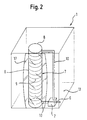
- Figure 2 shows a fourth embodiment, in which the display means in the form of a Light guide 7 is formed.
- the light guide 7 is from the bottom surface 13 to one out the upper region of the liquid container 1, and has essentially one Cylindrical shape.
- the light guide 7 is connected to a light source 2, either is connected directly to the light guide 7, or via a coupling guide 10 is optically coupled to the light guide 7.
- the arrangement of the light source 2 and the The light source 2 is preferably coupled in the upper / lower end of the light guide 7.
- the light guide 7 has an outer surface, which depends on whether liquid the outer surface is adjacent or not, a different reflection behavior in relation on the light guided in the light guide 7.
- the different reflection behavior of the Light guide 7 increased in that a coating 8 on the surface of the light guide 7 is applied, which depends on a strong change in the reflection behavior of whether liquid or air is present on the coating.
- the outer surface of the Optical fiber has mechanical structures that are different Reflection behavior during the transition of the light guide 7 from liquid to air additionally emphasizes.
- these mechanical structures are transverse grooves that in the Light guides 7 are introduced.
- the mechanical structures 9 are arranged in the region of the light guide 7, which one Sight glass is assigned.
- a sight glass 17 is in the container wall of the Liquid container 1 arranged in the region of the light guide 7 or the tube 3. On in this way the container wall is made transparent in this area.
- the Level indicator is preferred for coffee machines or kettles used.
Landscapes
- Physics & Mathematics (AREA)
- Fluid Mechanics (AREA)
- General Physics & Mathematics (AREA)
- Electromagnetism (AREA)
- Thermal Sciences (AREA)
- Cookers (AREA)
- Devices For Indicating Variable Information By Combining Individual Elements (AREA)
Abstract
Description
- Fig. 1
- ein Anzeigemittel in Form eines Rohres und
- Fig. 2
- ein Anzeigemittel in Form eines Lichtleiters.
- 1
- Flüssigkeitsbehälter
- 2
- Lichtquelle
- 3
- Rohr
- 4
- Öffnung
- 5
- Schwimmkörper
- 6
- elektrische Leitung
- 7
- Lichtleiter
- 8
- Beschichtung
- 9
- Struktur
- 10
- Kopplungsleitung
- 11
- Flüssigkeit
- 12
- Innenkanal
- 13
- Bodenfläche
- 14
- Oberseite
- 15
- Unterseite
- 16
- Seitenrand
- 17
- Schauglas
Claims (9)
- Füllstandsanzeige für ein Medium, insbesondere Flüssigkeit, mit einem lichtdurchlässigen Anzeigemittel, wobei das Anzeigemittel in Abhängigkeit davon, welches Medium an das Anzeigemittel angrenzt unterschiedliche optische Eigenschaften aufweist, so daß im Grenzbereich zwischen zwei Medien ein optischer Effekt auftritt, der den Füllstand eines Mediums anzeigt, dadurch gekennzeichnet, daß eine Lichtquelle (2) vorgesehen ist, die an das Anzeigemittel (7, 3, 12) angeschlossen ist.
- Füllstandsanzeige nach Anspruch 1, dadurch gekennzeichnet, daß das Anzeigemittel als Rohr (3) mit einem Innenkanal (12) ausgebildet ist, daß das Rohr (3) lichtdurchlässig ist, daß das Rohr (3) mindestens teilweise seitlich geöffnet ist, und daß die Lichtquelle (2) an den Innenkanal (12) angeschlossen ist.
- Füllstandsanzeige nach Anspruch 2, dadurch gekennzeichnet, daß das Rohr (3) aus Plexiglas oder einem durchsichtigen Kunststoff gebildet ist.
- Füllstandsanzeige nach einem der Ansprüche 2 oder 3, dadurch gekennzeichnet, daß im Innenkanal (12) ein Schwimmkörper (5) angeordnet ist, daß der Schwimmkörper (5) die Ausbreitung des Lichtes im Innenkanal (12) beeinflusst.
- Füllstandsanzeige nach einem der Ansprüche 2 bis 4, dadurch gekennzeichnet, daß der Schwimmkörper (5) auf der Unter- bzw. Oberseite (15, 14) lichtdurchlässig ist, und daß der Schwimmkörper (5) Licht, das von der Unter- oder Oberseite (15, 14) aufgenommen wird, seitlich nach außen mindestens teilweise abgibt.
- Füllstandsanzeige nach Anspruch 1, dadurch gekennzeichnet, daß das Anzeigemittel als Lichtleiter (7) ausgebildet ist.
- Füllstandsanzeige nach Anspruch 6, dadurch gekennzeichnet, daß die Oberfläche des Lichtleiters (7) eine Beschichtung (8) aufweist, die unterschiedliche Brechungsindizes in Bezug auf das im Lichtleiter (7) geführte Licht aufweist, in Abhängigkeit von dem Medium, das an die Beschichtung (8) angrenzt.
- Füllstandsanzeige nach Anspruch 6, dadurch gekennzeichnet, daß die Oberfläche des Lichtleiters (7) eine mechanische Struktur (9) aufweist, die unterschiedliche Brechungsindizes in Bezug auf das im Lichtleiter (7) geführte Licht aufweist, in Abhängigkeit von dem Medium, das an die Struktur (9) angrenzt.
- Elektrisches Haushaltsgerät mit einer Füllstandsanzeige nach einem der vorhergehenden Ansprüche.
Applications Claiming Priority (2)
| Application Number | Priority Date | Filing Date | Title |
|---|---|---|---|
| DE2000122591 DE10022591C2 (de) | 2000-05-09 | 2000-05-09 | Füllstandsanzeiger mit Lichtquelle |
| DE10022591 | 2000-05-09 |
Publications (2)
| Publication Number | Publication Date |
|---|---|
| EP1154246A2 true EP1154246A2 (de) | 2001-11-14 |
| EP1154246A3 EP1154246A3 (de) | 2003-10-15 |
Family
ID=7641325
Family Applications (1)
| Application Number | Title | Priority Date | Filing Date |
|---|---|---|---|
| EP01110683A Withdrawn EP1154246A3 (de) | 2000-05-09 | 2001-05-02 | Füllstandsanzeige mit Lichtquelle |
Country Status (2)
| Country | Link |
|---|---|
| EP (1) | EP1154246A3 (de) |
| DE (1) | DE10022591C2 (de) |
Cited By (4)
| Publication number | Priority date | Publication date | Assignee | Title |
|---|---|---|---|---|
| EP2087819A1 (de) * | 2008-02-05 | 2009-08-12 | MELITTA HAUSHALTSPRODUKTE GmbH & Co. Kommanditgesellschaft | Maschine zur Zubereitung eines Getränks |
| EP2412282A1 (de) * | 2010-07-28 | 2012-02-01 | Eugster/Frismag AG | Kaffeezubereitungsgerät mit wenigstens einem Zubereitungsgutbehälter mit einer Füllstandsanzeige |
| EP2719311A1 (de) * | 2012-10-15 | 2014-04-16 | Melitta Europa GmbH & Co. KG | Wassertank für ein Haushaltsgerät und Haushaltsgerät |
| RU178306U1 (ru) * | 2016-10-12 | 2018-03-29 | Альберт Галиуллович Абдуллин | Лазерный уровнемер жидкости |
Families Citing this family (3)
| Publication number | Priority date | Publication date | Assignee | Title |
|---|---|---|---|---|
| DE10017550A1 (de) * | 2000-04-08 | 2001-10-18 | Fluidtech Gmbh | Vorrichtung zum Anzeigen und Kontrollieren von Fluidzuständen |
| CN106382971B (zh) * | 2016-11-10 | 2017-12-19 | 中国矿业大学(北京) | 多功能微光地下水位监测装置及其系统 |
| DE102018118178A1 (de) * | 2018-07-27 | 2020-01-30 | Miele & Cie. Kg | Behälter zur Aufnahme und Abgabe eines Duftstoffs in den Behandlungsraum eines Haushaltsgeräts sowie Haushaltsgerät mit einem derartigen Behälter |
Family Cites Families (9)
| Publication number | Priority date | Publication date | Assignee | Title |
|---|---|---|---|---|
| AT263405B (de) * | 1965-04-29 | 1968-07-25 | Hectronic Ag | Lichtelektrischer Flüssigkeitsdetektor |
| DE2038860A1 (de) * | 1970-08-05 | 1972-02-10 | Otto & Co Gmbh Dr C | Gegenstromkolonne |
| GB1603389A (en) * | 1978-05-31 | 1981-11-25 | Eaton S | Liquid level detector |
| DE3328141A1 (de) * | 1983-08-04 | 1985-02-21 | kabelmetal electro GmbH, 3000 Hannover | Vorrichtung zur ueberwachung eines fluessigkeitsspiegels |
| US4745293A (en) * | 1987-03-23 | 1988-05-17 | Cv Technology, Inc. | Method and apparatus for optically measuring fluid levels |
| DE4011651A1 (de) * | 1990-04-11 | 1991-10-17 | Braun Ag | Pegelstandanzeigeeinrichtung fuer einen wasservorratsbehaelter von haushaltsgeraeten |
| DE4217669A1 (de) * | 1992-05-28 | 1993-04-01 | Daimler Benz Ag | Vorrichtung zur fuellstandsmessung einer fluessigkeit in einem fluessigkeitsbehaelter |
| IT1283694B1 (it) * | 1996-08-06 | 1998-04-23 | Fitre S P A | Sensore ad azionamento magnetico per livello liquidi o parti in movimento |
| GB2332522A (en) * | 1997-11-27 | 1999-06-23 | Otter Controls Ltd | Liquid level indication device |
-
2000
- 2000-05-09 DE DE2000122591 patent/DE10022591C2/de not_active Expired - Fee Related
-
2001
- 2001-05-02 EP EP01110683A patent/EP1154246A3/de not_active Withdrawn
Cited By (6)
| Publication number | Priority date | Publication date | Assignee | Title |
|---|---|---|---|---|
| EP2087819A1 (de) * | 2008-02-05 | 2009-08-12 | MELITTA HAUSHALTSPRODUKTE GmbH & Co. Kommanditgesellschaft | Maschine zur Zubereitung eines Getränks |
| EP2412282A1 (de) * | 2010-07-28 | 2012-02-01 | Eugster/Frismag AG | Kaffeezubereitungsgerät mit wenigstens einem Zubereitungsgutbehälter mit einer Füllstandsanzeige |
| CN102342755A (zh) * | 2010-07-28 | 2012-02-08 | 优格斯特/弗里斯马格股份公司 | 具有至少一个带有填充料位指示的烹调物容器的咖啡烹调器 |
| CN102342755B (zh) * | 2010-07-28 | 2014-07-30 | 优格斯特/弗里斯马格股份公司 | 具有至少一个带有填充料位指示的烹调物容器的咖啡烹调器 |
| EP2719311A1 (de) * | 2012-10-15 | 2014-04-16 | Melitta Europa GmbH & Co. KG | Wassertank für ein Haushaltsgerät und Haushaltsgerät |
| RU178306U1 (ru) * | 2016-10-12 | 2018-03-29 | Альберт Галиуллович Абдуллин | Лазерный уровнемер жидкости |
Also Published As
| Publication number | Publication date |
|---|---|
| DE10022591C2 (de) | 2002-09-12 |
| EP1154246A3 (de) | 2003-10-15 |
| DE10022591A1 (de) | 2001-11-29 |
Similar Documents
| Publication | Publication Date | Title |
|---|---|---|
| DE3526511C2 (de) | ||
| DE68918999T2 (de) | Lichtquelle. | |
| EP0078939B1 (de) | Stabähnliche Vorrichtung zum Erfassen des jeweiligen Niveaus von Flüssigkeiten in Behältern, Kanälen o. dgl. | |
| DE3513693A1 (de) | Fluessigkeitspegel-anzeigevorrichtung, insbesondere fuer raumluftbefeuchter | |
| EP0850799B1 (de) | Anzeigeeinheit mit durchleuchtbarem Anzeigeelement | |
| DE102006008191B4 (de) | Leuchteneinheit für Fahrzeuge | |
| DE10022591A1 (de) | Füllstandsanzeige mit Lichtquelle | |
| DE3712699A1 (de) | Sensor | |
| DE1549000B2 (de) | Optischer Flüssigkeitsstandanzeiger | |
| DE10210161A1 (de) | Getränkebereiter, insbesondere Kaffeemaschine | |
| WO2004056256A1 (de) | Haushaltgerät, insbesondere einbau-haushaltgerät | |
| EP1943930B1 (de) | Getränkemaschine | |
| DE102017129978A1 (de) | Linienförmige Lichtquelle | |
| DE1548983C3 (de) | Lichtelektrischer Flüssigkeitsdetektor für die Flüssigkeitsstandanzeige | |
| DE102017125212B4 (de) | Linse und leuchtmodul | |
| CH669615A5 (de) | ||
| DE202008016449U1 (de) | Behälter mit einem Raum zum Fassen einer Flüssigkeit, mit Mitteln zur Anzeige eines Pegels der Flüssigkeit | |
| DE102017201125A1 (de) | Anzeigevorrichtung und damit ausgestattetes elektronisches Gerät | |
| DE10306870A1 (de) | Leuchtanzeigeeinrichtung | |
| DE10008062B4 (de) | LED-Display-Modul | |
| DE2804639B2 (de) | Füllstandsanzeiger | |
| DE3417023C2 (de) | Sensor zum Messen des Füllstandes einer Flüssigkeit | |
| DE3703629A1 (de) | Fuellstandsanzeiger | |
| DE202004013837U1 (de) | Beleuchtung eines LCD-Displays | |
| EP0438768A1 (de) | Leuchtbox |
Legal Events
| Date | Code | Title | Description |
|---|---|---|---|
| PUAI | Public reference made under article 153(3) epc to a published international application that has entered the european phase |
Free format text: ORIGINAL CODE: 0009012 |
|
| AK | Designated contracting states |
Kind code of ref document: A2 Designated state(s): AT BE CH CY DE DK ES FI FR GB GR IE IT LI LU MC NL PT SE TR |
|
| AX | Request for extension of the european patent |
Free format text: AL;LT;LV;MK;RO;SI |
|
| PUAL | Search report despatched |
Free format text: ORIGINAL CODE: 0009013 |
|
| AK | Designated contracting states |
Kind code of ref document: A3 Designated state(s): AT BE CH CY DE DK ES FI FR GB GR IE IT LI LU MC NL PT SE TR |
|
| AX | Request for extension of the european patent |
Extension state: AL LT LV MK RO SI |
|
| RAP1 | Party data changed (applicant data changed or rights of an application transferred) |
Owner name: BSH BOSCH UND SIEMENS HAUSGERAETE GMBH |
|
| 17P | Request for examination filed |
Effective date: 20040415 |
|
| AKX | Designation fees paid |
Designated state(s): AT BE CH CY DE DK ES FI FR GB GR IE IT LI LU MC NL PT SE TR |
|
| STAA | Information on the status of an ep patent application or granted ep patent |
Free format text: STATUS: THE APPLICATION IS DEEMED TO BE WITHDRAWN |
|
| 18D | Application deemed to be withdrawn |
Effective date: 20091201 |