EP1154169A1 - Connector assembly with a lock of the bayonet type - Google Patents
Connector assembly with a lock of the bayonet type Download PDFInfo
- Publication number
- EP1154169A1 EP1154169A1 EP01401151A EP01401151A EP1154169A1 EP 1154169 A1 EP1154169 A1 EP 1154169A1 EP 01401151 A EP01401151 A EP 01401151A EP 01401151 A EP01401151 A EP 01401151A EP 1154169 A1 EP1154169 A1 EP 1154169A1
- Authority
- EP
- European Patent Office
- Prior art keywords
- lug
- connector assembly
- set forth
- ramp
- ring
- Prior art date
- Legal status (The legal status is an assumption and is not a legal conclusion. Google has not performed a legal analysis and makes no representation as to the accuracy of the status listed.)
- Granted
Links
- 238000006073 displacement reaction Methods 0.000 claims description 4
- 230000000295 complement effect Effects 0.000 claims description 3
- 238000009434 installation Methods 0.000 claims description 2
- 230000000712 assembly Effects 0.000 description 3
- 238000000429 assembly Methods 0.000 description 3
- 238000003780 insertion Methods 0.000 description 2
- 230000037431 insertion Effects 0.000 description 2
- 230000014759 maintenance of location Effects 0.000 description 1
- 230000002035 prolonged effect Effects 0.000 description 1
Images

Classifications
-
- F—MECHANICAL ENGINEERING; LIGHTING; HEATING; WEAPONS; BLASTING
- F16—ENGINEERING ELEMENTS AND UNITS; GENERAL MEASURES FOR PRODUCING AND MAINTAINING EFFECTIVE FUNCTIONING OF MACHINES OR INSTALLATIONS; THERMAL INSULATION IN GENERAL
- F16B—DEVICES FOR FASTENING OR SECURING CONSTRUCTIONAL ELEMENTS OR MACHINE PARTS TOGETHER, e.g. NAILS, BOLTS, CIRCLIPS, CLAMPS, CLIPS OR WEDGES; JOINTS OR JOINTING
- F16B21/00—Means for preventing relative axial movement of a pin, spigot, shaft or the like and a member surrounding it; Stud-and-socket releasable fastenings
- F16B21/02—Releasable fastening devices locking by rotation
- F16B21/04—Releasable fastening devices locking by rotation with bayonet catch
-
- H—ELECTRICITY
- H01—ELECTRIC ELEMENTS
- H01R—ELECTRICALLY-CONDUCTIVE CONNECTIONS; STRUCTURAL ASSOCIATIONS OF A PLURALITY OF MUTUALLY-INSULATED ELECTRICAL CONNECTING ELEMENTS; COUPLING DEVICES; CURRENT COLLECTORS
- H01R13/00—Details of coupling devices of the kinds covered by groups H01R12/70 or H01R24/00 - H01R33/00
- H01R13/62—Means for facilitating engagement or disengagement of coupling parts or for holding them in engagement
- H01R13/625—Casing or ring with bayonet engagement
Definitions
- the present invention bas for object a connector assembly with a lock of the bayonet type. It is applied more specially in the field of the connection assemblies comprising at least a base and a complementary pin, the pin being mounted in the base and being held on the base by means of a locking ring co-operating with a locking lug on the base.
- the interest of the invention is to propose a connector assembly the locking of which is guaranteed even when the connector assembly is placed in difficult mechanical conditions.
- a connector assembly with a lock of the bayonet type is known from the state of the art, particularly from the teachings of the document US 5 397 196.
- a connector assembly according to this document consists of a base having locking lugs, and a pin comprising a pin body and a locking ring.
- the locking ring has ramps, each ramp being able to cooperate with one lug.
- a movement of one lug in a ramp is generally limited by an end stop on the ramp.
- a ramp of the locking ring is characterized by a width. Adjacent a zone for inserting the lug in the ramp, the width of the ramp is larger than a diameter of the lug. Toward an end of the ramp located close to the end stop, the width of the ramp is progressively reduced below the diameter of the lug. Nevertheless, the movement of the lug can however be completed at the end stop because the width of the ramp can be increased elastically adjacent the end of the ramp.
- the ramp adjacent the end which is close to the end stop, the ramp comprises an elastic beam.
- the elastic beam is positioned transversally in relation to the ramp in order to decrease the 'width thereof. But the elastic beam can be pushed in a recess of the ring, in order to provide a ramp with a width allowing the passage of the lug toward the end stop. For instance, the beam is pushed by the lug itself when the lug is locked on the ramp of the ring.
- the lug has a cylindrical shape.
- the cutout at the free end of the beam is then shaped as an arc of a circle matching a portion of an outer periphery of the lug.
- the elastic beam is shaped as a prolonged parallelepiped, such that the first end having the cutout is presented opposite a second end, such second end being embedded for instance in the locking ring.
- the elastic beam comprises a step between an upper sliding surface of the beam and the cutout.
- the sliding surface is a surface of the elastic beam on which the lug is forced when it is moved toward the end stop.
- the step allows to guarantee the retention of the lug against the end stop.
- the force necessary to unlock the connector assembly becomes higher with a steeper ramp. Namely, in order t. unlock the connector assembly, a sufficient rotation force has to be exerted so that t-he lug is moved out of the cutout and moves the cutout of the ramp toward a displaced position.
- the known connector assembly Since the known connector assembly is designed to be manipulated by band, the force which has to be applied to allow the lug to be moved from its position against the end stop is moderate.
- the step generally has an obtuse shape. Therefore, since the necessary unlocking force is lesser, when the connector assembly is exposed to strong vibrations, these vibrations can play the role of an unlocking force and move the lug from its position against the end stop.
- connection assemblies with a lock of the bayonet type of the state of the art have a. problem when they are placed in difficult mechanical conditions. Thus, for instance, in strong vibratory conditions, the connection assemblies may unlock by themselves. There is a risk of disconnection of the base and the base.
- An object of the invention is to remedy such problem by means of the provision of a connector assembly with a lock comprising a wedge to maintain the position of the elastic beam against the lug when the lug is located against the end stop.
- the wedge prevents the lug to be moved from its position against the end stop whatever be the force applied on the unlocking ring and whatever be the mechanical and notably vibratory conditions in which the connector assembly is placed.
- the locking ring according to the invention comprises an opening able to be accessed from an outer surface.
- the elastic beam defines in the opening an upper slot and a. lower lot.
- the upper slot is able to receive the lug until it reaches its position against the end stop, and the lower slot corresponds to the space between the beam and the recess in which the beam is able to be forced.
- the wedge is arranged preferably in the lower slot so that the elastic beam cannot be forced further and to prevent a movement of the lug thus lying completely in the upper slot.
- the wedge can be a pin with a handle which is pushed in forcibly in order to prevent the movement of the elastic beam after the locking. The pin must be withdrawn to allow the connector assembly to be unlocked.
- An object of the invention is a connector assembly comprising a base and a pin, the base comprising at base and a pin, the base comprising one locking lug; and the pin comprising a pin body and a locking ring, the ring comprising at least one ramp to receive the lug, the ramp being hindered by an elastic element, the elastic element; defining in the ramp an upper slot in which the lug is able to be moved, and a lower slot toward which the elastic element can be pushed, characterized in that it comprises a removable locking member, the locking member being able to be arranged in the lower slot to block the displacement of the plastic element.
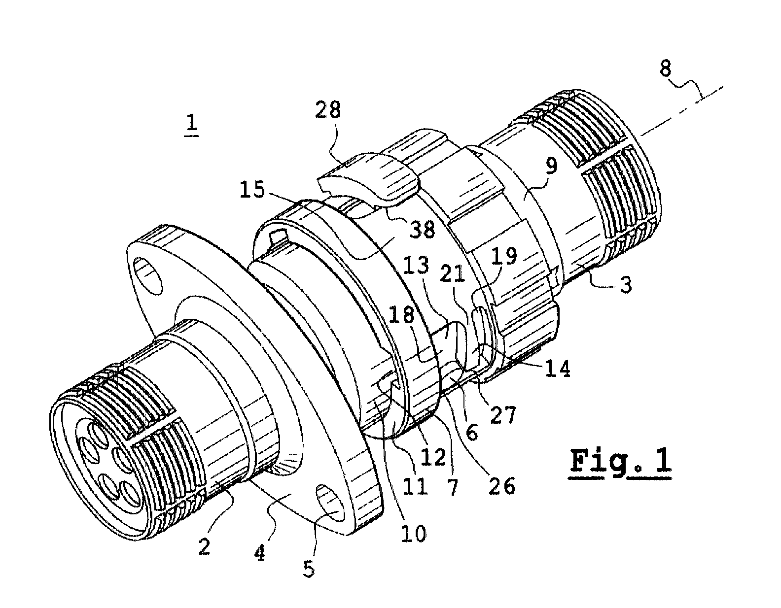
- FIG. 1 shows a connector assembly I according to the invention.
- the connector assembly I comprises a base 2 and a pin 3.
- the pin 3 is complementary to the base 2.
- the base 2 and the pin 3 are designed preferably to receive cables.
- the base 2 is able to be mounted rigidly on a support by means of a flange 4.
- the flange 4 has openings 5 allowing it to be for instance screwed in the support.
- the base 2 comprises a locking lug 6.
- the pin 3 comprises a locking ring 7 to cooperate with the lug 6.
- the ring 7 can slide longitudinally along the connector assembly I along an axis 8. Otherwise, the ring 7 is able to rotate freely about a pin body 9 of the pin 3.
- the lug 6 extends beyond an outer periphery 10 of the base 2.
- the outer periphery 10 has a cylindrical shape.
- the lug 6 is cylindrical and comprises an axis of revolution oriented radially in relation to the outer periphery 10.
- the ring 7 comprises a front face 11.
- the front face 11 is perpendicular to the axis 8.
- the front. face 11 comprises an inlet 12.
- the inlet 12 corresponds to an internal cutout of the locking ring 7, so that the lug 6 is able pass in the direction of a ramp 13 on the locking ring 7. Namely, when the locking ring 7 is longitudinally transferred along the axis a toward the flange 4, the locking ring 7 is rotated previously in order to position the opening 12 opposite the lug 6.
- the transfer of the locking ring 7 is limited by an element 14 positioned perpendicularly to the axis of transfer, and preferably positioned in an extension of an outer surface 15 of the ring 7.
- the outer surface 15 bas preferably a cylindrical form, and therefore the element 14 is also contained in the cylindrical profile.
- the element corresponds to a cutout in the outer surface 15. limit the transfer of the locking ring 7 when the opening 12 is positioned opposite the lug 6.
- the lug 6 abuts an edge 16 of the element 14, the edge 16 able to be aligned with the opening 12.
- the element 14 is for instance a beam which is fitted in the outer surface 15, preferably adjacent the edge 16.
- the outer surface 15 comprises an opening 17 in which the element 14 extends, so that the element 14 defines an upper slot 18 and a lower slot 19 in the opening 17.
- the upper slot 18 is in communication with the inlet 12.
- the element 14 comprises a free end 20, the free end 20 being located opposite a fixed end 21 of the beam 14, the fixed end 21 corresponding to the attachment point of the beam 14, for instance adjacent the edge 16.
- the free end 20 can be slightly mobile inside the opening 17. When the element 14 is displaced inside the opening 17, the dimensions of the slots 18 and 19 are each modified.
- the upper slot 18 Adjacent the edge 16, the upper slot 18 has a width 22. Adjacent a step 23 of the free end 20, the upper slot 18 has a width 24.
- the width 24 is variable according to the position of the free end 20 inside the opening 17.
- the width 22 is larger than a diameter 25 of the lug 6.
- the width 24 is smaller than the diameter 25 when the lug 6 is displaced in the upper slot 18.
- the elastic element. 14 can be displaced in the opening 17 so that the width 24 becomes equal to the diameter 25.
- the lug 6 When the lug 6 passes beyond the step 23 while pushing the beam 14 in a flexible manner toward the lower slot 19, the lug 6 abuts an edge 26, the edge 26 being diametrically opposed to the edge 16.
- a cutout 27 of the free end 20 rests on a periphery of the lug 6. In this position, the elastic element 14 is at rest. A distance between the edge 26 and the cutout 27 is then equal to the diameter 25. In this position, the width 24 is smaller than the diameter 25. Therefore, in this position, the lug 6 is held by a constriction formed by the step 23.
- the connector assembly 1 comprises a locking member 28, showed in figure 3, such that the locking member 28 can be inserted in the lower slot 19 in order to prevent the displacement of the elastic element 14 in the lower slot 19 and also to prevent the width 24 to be increased in order to allow the lug 6 to pass when the lug is blocked between the cutout 27 and the edge 26.
- the locking member 28 is mounted preferably on the ring 7 from the outer surface 15
- the locking member 28 comprises a step 29.
- the step 29 is dimensioned so as to match the shape of the lower slot 19 when the elastic beam 14 is at rest.
- the step 29 has a parallelepipedal shape.
- the step 29 since the step 29 is designed to be forcibly inserted in the lower slot 19, the step 29 comprises preferably a bevel 30, such that the bevel 30 forms an large angle in order to facilitate the insertion of the step 29 in the lower slot 19.in the lower slot 19.
- an insertion face 31 of the step 29 is dimensioned distinctly smaller than the shape of the lower slot 19, whereas an upper periphery 32 of the step is dimensioned slightly larger than the shape of the lower slot 19.
- the looking member 28 comprises an upper plate 33.
- the upper plat-e 33 has a dimension which is larger than dimensions of the lower slot 19.
- the locking member 28 still has the outer plate 33 extending from the outer periphery 15 of the ring 7.
- the outer plate 33 is designed to facilitate the installation and/or the disassembly of the locking member 28. Particularly when considering the large size of the outer plate 33, the locking member 28 is easy to manipulate.
- the upper plate 33 has prehension means. Namely, the upper plate 33 comprises a small wing 34, the small wing 34 having such a thickness 35 that the thickness 35 is smaller. than a. thickness 36 of a region of the upper plate 33 located adjacent the step 29.
- the small wing 34 has a face 37 facing the outer surface 15 of the ring 7 when the locking member 28 is mounted in the lower slot 19.
- the locking member 28 has a space 38 between the face 37 of t-he small wing 34 and the outer face 15 of the ring 7.
- a screwdriver can be inserted in this space 38 to act as a lever and so to dislodge the locking member 28 from its position in the lower slot 19-
- the locking member 28 is withdrawn, the mobility of the elastic element 14 is returned, and so, when the ring 7 is rotated about the axis 8, the lug 6 can be unlocked from its position between the edge 26 and the cutout. 27 while clearing the constriction adjacent. the step 23 and pushing the elastic element 14 toward the lower slot 19.
- the base 2 comprises three lugs like lug 6 and in correspondence, the ring 7 of the pin 3 comprises three ramps like ramp 13, whereas the lugs and respectively the ramps being arranged at 120 degrees from each other.
- the connector base 1 may require the use of three locking members 27.
Abstract
Description
- The present invention bas for object a connector assembly with a lock of the bayonet type. It is applied more specially in the field of the connection assemblies comprising at least a base and a complementary pin, the pin being mounted in the base and being held on the base by means of a locking ring co-operating with a locking lug on the base. The interest of the invention is to propose a connector assembly the locking of which is guaranteed even when the connector assembly is placed in difficult mechanical conditions.
- A connector assembly with a lock of the bayonet type is known from the state of the art, particularly from the teachings of the document US 5 397 196. A connector assembly according to this document consists of a base having locking lugs, and a pin comprising a pin body and a locking ring. The locking ring has ramps, each ramp being able to cooperate with one lug. A movement of one lug in a ramp is generally limited by an end stop on the ramp.
- A ramp of the locking ring is characterized by a width. Adjacent a zone for inserting the lug in the ramp, the width of the ramp is larger than a diameter of the lug. Toward an end of the ramp located close to the end stop, the width of the ramp is progressively reduced below the diameter of the lug. Nevertheless, the movement of the lug can however be completed at the end stop because the width of the ramp can be increased elastically adjacent the end of the ramp.
- Namely, adjacent the end which is close to the end stop, the ramp comprises an elastic beam. The elastic beam is positioned transversally in relation to the ramp in order to decrease the 'width thereof. But the elastic beam can be pushed in a recess of the ring, in order to provide a ramp with a width allowing the passage of the lug toward the end stop. For instance, the beam is pushed by the lug itself when the lug is locked on the ramp of the ring.
- Therefore, 'When an user displaces the lug on the ramp, preferably during a rotation of the ring in relation to the base on which the lug is located, a resistance to the rotation is felt by the user. 'The lug is forced against the elastic beam in order to push the elastic beam in its recess and thus to allow the passage of the lug toward the end stop. Moreover, when the lug reaches the end stop, the elastic beam returns in an unstressed rest position, in which a free end of the elastic beam comprises a cutout to keep the lug in its position against the end stop.
- In a preferred example, the lug has a cylindrical shape. Preferably, the cutout at the free end of the beam is then shaped as an arc of a circle matching a portion of an outer periphery of the lug. Preferably, the elastic beam is shaped as a prolonged parallelepiped, such that the first end having the cutout is presented opposite a second end, such second end being embedded for instance in the locking ring.
- The elastic beam comprises a step between an upper sliding surface of the beam and the cutout. The sliding surface is a surface of the elastic beam on which the lug is forced when it is moved toward the end stop. The step allows to guarantee the retention of the lug against the end stop. The force necessary to unlock the connector assembly becomes higher with a steeper ramp. Namely, in order t. unlock the connector assembly, a sufficient rotation force has to be exerted so that t-he lug is moved out of the cutout and moves the cutout of the ramp toward a displaced position.
- Since the known connector assembly is designed to be manipulated by band, the force which has to be applied to allow the lug to be moved from its position against the end stop is moderate. The step generally has an obtuse shape. Therefore, since the necessary unlocking force is lesser, when the connector assembly is exposed to strong vibrations, these vibrations can play the role of an unlocking force and move the lug from its position against the end stop.
- The connection assemblies with a lock of the bayonet type of the state of the art have a. problem when they are placed in difficult mechanical conditions. Thus, for instance, in strong vibratory conditions, the connection assemblies may unlock by themselves. There is a risk of disconnection of the base and the base.
- An object of the invention is to remedy such problem by means of the provision of a connector assembly with a lock comprising a wedge to maintain the position of the elastic beam against the lug when the lug is located against the end stop. The wedge prevents the lug to be moved from its position against the end stop whatever be the force applied on the unlocking ring and whatever be the mechanical and notably vibratory conditions in which the connector assembly is placed. When the lug is unlocked, the elastic beam is pushed in a recess. To facilitate the positioning of the wedge, the locking ring according to the invention comprises an opening able to be accessed from an outer surface.
- The elastic beam defines in the opening an upper slot and a. lower lot. The upper slot is able to receive the lug until it reaches its position against the end stop, and the lower slot corresponds to the space between the beam and the recess in which the beam is able to be forced. The wedge is arranged preferably in the lower slot so that the elastic beam cannot be forced further and to prevent a movement of the lug thus lying completely in the upper slot. The wedge can be a pin with a handle which is pushed in forcibly in order to prevent the movement of the elastic beam after the locking. The pin must be withdrawn to allow the connector assembly to be unlocked.
- An object of the invention is a connector assembly comprising a base and a pin, the base comprising at base and a pin, the base comprising one locking lug; and the pin comprising a pin body and a locking ring, the ring comprising at least one ramp to receive the lug, the ramp being hindered by an elastic element, the elastic element; defining in the ramp an upper slot in which the lug is able to be moved, and a lower slot toward which the elastic element can be pushed, characterized in that it comprises a removable locking member, the locking member being able to be arranged in the lower slot to block the displacement of the plastic element.
- The invention will be better understood when reading the following description with reference to the attached figures. These figures are merely illustrative and should not be considered as restricting the invention in any way. Among the figures:
- Figure 1: shows a schematic view of a connector assembly locked according to the invention;
- Figure 2: shows an enlarged portion of a connector assembly according to the invention;
- Figure 3: shows a locking member of assembly according to the invention.
- Figure 1 shows a connector assembly I according to the invention. The connector assembly I comprises a
base 2 and a pin 3. The pin 3 is complementary to thebase 2. Thebase 2 and the pin 3 are designed preferably to receive cables. Moreover, thebase 2 is able to be mounted rigidly on a support by means of aflange 4. To this end, theflange 4 hasopenings 5 allowing it to be for instance screwed in the support. - The
base 2 comprises alocking lug 6. The pin 3 comprises alocking ring 7 to cooperate with thelug 6. Thering 7 can slide longitudinally along the connector assembly I along an axis 8. Otherwise, thering 7 is able to rotate freely about a pin body 9 of the pin 3. - The
lug 6 extends beyond anouter periphery 10 of thebase 2. Preferably, theouter periphery 10 has a cylindrical shape. In a preferred example, thelug 6 is cylindrical and comprises an axis of revolution oriented radially in relation to theouter periphery 10. - The
ring 7 comprises afront face 11. Thefront face 11 is perpendicular to the axis 8. The front.face 11 comprises aninlet 12. Theinlet 12 corresponds to an internal cutout of thelocking ring 7, so that thelug 6 is able pass in the direction of aramp 13 on thelocking ring 7. Namely, when thelocking ring 7 is longitudinally transferred along the axis a toward theflange 4, thelocking ring 7 is rotated previously in order to position theopening 12 opposite thelug 6. - The transfer of the
locking ring 7 is limited by anelement 14 positioned perpendicularly to the axis of transfer, and preferably positioned in an extension of anouter surface 15 of thering 7. However, theouter surface 15 bas preferably a cylindrical form, and therefore theelement 14 is also contained in the cylindrical profile. Preferably, the element corresponds to a cutout in theouter surface 15. limit the transfer of thelocking ring 7 when theopening 12 is positioned opposite thelug 6. Thelug 6 abuts anedge 16 of theelement 14, theedge 16 able to be aligned with theopening 12. - The
element 14 is for instance a beam which is fitted in theouter surface 15, preferably adjacent theedge 16. Theouter surface 15 comprises anopening 17 in which theelement 14 extends, so that theelement 14 defines anupper slot 18 and alower slot 19 in theopening 17. Theupper slot 18 is in communication with theinlet 12. - The
element 14 comprises afree end 20, thefree end 20 being located opposite afixed end 21 of thebeam 14, thefixed end 21 corresponding to the attachment point of thebeam 14, for instance adjacent theedge 16. Thefree end 20 can be slightly mobile inside theopening 17. When theelement 14 is displaced inside theopening 17, the dimensions of theslots - Adjacent the
edge 16, theupper slot 18 has awidth 22. Adjacent astep 23 of thefree end 20, theupper slot 18 has a width 24. The width 24 is variable according to the position of thefree end 20 inside theopening 17. Thewidth 22 is larger than adiameter 25 of thelug 6. On the other hand.. in a rest position of the elastic element. 14, the width 24 is smaller than thediameter 25 when thelug 6 is displaced in theupper slot 18. The elastic element. 14 can be displaced in theopening 17 so that the width 24 becomes equal to thediameter 25. - When the
lug 6 passes beyond thestep 23 while pushing thebeam 14 in a flexible manner toward thelower slot 19, thelug 6 abuts anedge 26, theedge 26 being diametrically opposed to theedge 16. When thelug 6 is received against theedge 26, acutout 27 of thefree end 20 rests on a periphery of thelug 6. In this position, theelastic element 14 is at rest. A distance between theedge 26 and thecutout 27 is then equal to thediameter 25. In this position, the width 24 is smaller than thediameter 25. Therefore, in this position, thelug 6 is held by a constriction formed by thestep 23. - The
connector assembly 1 according to the invention comprises a lockingmember 28, showed in figure 3, such that the lockingmember 28 can be inserted in thelower slot 19 in order to prevent the displacement of theelastic element 14 in thelower slot 19 and also to prevent the width 24 to be increased in order to allow thelug 6 to pass when the lug is blocked between thecutout 27 and theedge 26. - The locking
member 28 is mounted preferably on thering 7 from theouter surface 15 The lockingmember 28 comprises astep 29. In a preferred example, thestep 29 is dimensioned so as to match the shape of thelower slot 19 when theelastic beam 14 is at rest. Then, thestep 29 has a parallelepipedal shape. Besides, since thestep 29 is designed to be forcibly inserted in thelower slot 19, thestep 29 comprises preferably abevel 30, such that thebevel 30 forms an large angle in order to facilitate the insertion of thestep 29 in the lower slot 19.in thelower slot 19. Namely, aninsertion face 31 of thestep 29 is dimensioned distinctly smaller than the shape of thelower slot 19, whereas anupper periphery 32 of the step is dimensioned slightly larger than the shape of thelower slot 19. - Moreover, the looking
member 28 comprises anupper plate 33. The upper plat-e 33 has a dimension which is larger than dimensions of thelower slot 19. Thus, when thestep 29 is inserted in thelower slot 19, the lockingmember 28 still has theouter plate 33 extending from theouter periphery 15 of thering 7. Theouter plate 33 is designed to facilitate the installation and/or the disassembly of the lockingmember 28. Particularly when considering the large size of theouter plate 33, the lockingmember 28 is easy to manipulate. - Moreover, the
upper plate 33 has prehension means. Namely, theupper plate 33 comprises asmall wing 34, thesmall wing 34 having such athickness 35 that thethickness 35 is smaller. than a.thickness 36 of a region of theupper plate 33 located adjacent thestep 29. Thesmall wing 34 has aface 37 facing theouter surface 15 of thering 7 when the lockingmember 28 is mounted in thelower slot 19. Thus mounted, the lockingmember 28 has aspace 38 between theface 37 of t-hesmall wing 34 and theouter face 15 of thering 7. - For instance, a screwdriver can be inserted in this
space 38 to act as a lever and so to dislodge the lockingmember 28 from its position in the lower slot 19- When the lockingmember 28 is withdrawn, the mobility of theelastic element 14 is returned, and so, when thering 7 is rotated about the axis 8, thelug 6 can be unlocked from its position between theedge 26 and the cutout. 27 while clearing the constriction adjacent. thestep 23 and pushing theelastic element 14 toward thelower slot 19. - In a preferred embodiment of the invention, the
base 2 comprises three lugs likelug 6 and in correspondence, thering 7 of the pin 3 comprises three ramps likeramp 13, whereas the lugs and respectively the ramps being arranged at 120 degrees from each other. In such an embodiment., it can be foreseen that only one lockingmember 28 will be necessary to lock theconnector base 1. Nevertheless, theconnector base 1 may require the use of three lockingmembers 27.
Claims (12)
- A connector assembly (1) comprising a base (2) and a pin (3), the base comprising at least one locking lug (6) and the pin comprising a pin body (9) and a locking ring (7), the ring comprising at least one ramp (13) to receive the lug, the ramp being hindered by an elastic element (14), the elastic element defining in the ramp an upper slot (18) in which the lug is able to move, and a lower slot (19) toward which the elastic element can be pushed, characterized in that it comprises a removable locking member (28), the locking member being able to be arranged in the lower slot to block the displacement: of the plastic element
- A connector assembly as set forth in claim 1, characterized in that the lower slot is able to be accessed from an outer surface (15) of the ring.
- A connector assembly as set forth in claim characterized in that the locking member is mounted in the lower slot from the outer surface of the ring.
- A connector assembly as set forth in one of claims 1 to 3, characterized in that the locking member comprises a step (29) with a bevel (30), the bevelled step being designed to be forcibly pushed with a handle in the lower slot.
- A connector assembly as set forth in one of claims I to 4, characterized in that the locking member comprises an upper plate (33) having a dimension larger than the lower slot, and designed to facilitate the installation or the disassembly of the locking member.
- A connector assembly as set forth in claim 5, characterized in that the upper plate comprises at least one small wing (34), such that a space (38) is defined between the small wing and an outer surface of the ring.
- A connector assembly as set forth in one of claims I to 6, characterized in that the ramp inlet (12) adjacent front face (11) of allow the passage of the lug in the ramp.
- A connector assembly as set forth in one of claims I to 7, characterized in that the elastic element is a flexible tan, the flexible tab comprising a free end (20) to prevent a displacement of the lug toward the lower slot.
- A connector assembly as set forth in claim 8, characterized in that the free end comprises complementary cutout (27) to receive the lug.
- A connector assembly as set forth in one of claims 1 to 9, characterized in that the elastic element comprises a step (23) forming a neck.
- A connector assembly as set forth in one of claims I to 10, characterized in that a width (24) of the upper slot is smaller than a diameter (25) of the lug.
- A connector assembly as set forth in one of claims 1 to 11, characterized in that the base comprises three lugs and the ring comprises three ramps arranged at 120° from each other, respectively.
Applications Claiming Priority (2)
| Application Number | Priority Date | Filing Date | Title |
|---|---|---|---|
| FR0005748A FR2808570B1 (en) | 2000-05-04 | 2000-05-04 | BAYONET TYPE LOCKING CONNECTION ASSEMBLY |
| FR0005748 | 2000-05-04 |
Publications (2)
| Publication Number | Publication Date |
|---|---|
| EP1154169A1 true EP1154169A1 (en) | 2001-11-14 |
| EP1154169B1 EP1154169B1 (en) | 2003-05-02 |
Family
ID=8849920
Family Applications (1)
| Application Number | Title | Priority Date | Filing Date |
|---|---|---|---|
| EP01401151A Expired - Lifetime EP1154169B1 (en) | 2000-05-04 | 2001-05-03 | Connector assembly with a lock of the bayonet type |
Country Status (5)
| Country | Link |
|---|---|
| EP (1) | EP1154169B1 (en) |
| AT (1) | ATE239178T1 (en) |
| DE (1) | DE60100223T2 (en) |
| ES (1) | ES2198387T3 (en) |
| FR (1) | FR2808570B1 (en) |
Cited By (1)
| Publication number | Priority date | Publication date | Assignee | Title |
|---|---|---|---|---|
| EP2407643A1 (en) * | 2010-07-15 | 2012-01-18 | Siemens Aktiengesellschaft | Bore-scope sealing apparatus |
Families Citing this family (2)
| Publication number | Priority date | Publication date | Assignee | Title |
|---|---|---|---|---|
| FR3031245B1 (en) | 2014-12-24 | 2016-12-23 | Radiall Sa | CONNECTION ASSEMBLY WITH BAY-CONNECTION LATCH CONNECTION ELEMENTS |
| FR3068092B1 (en) * | 2017-06-26 | 2019-08-23 | Souriau | BAIONNETTE LOCKING AND UNLOCKING SYSTEM FOR CIRCULAR CONNECTOR WITH SOUND INDICATOR |
Citations (3)
| Publication number | Priority date | Publication date | Assignee | Title |
|---|---|---|---|---|
| US4464001A (en) * | 1982-09-30 | 1984-08-07 | The Bendix Corporation | Coupling nut having an anti-decoupling device |
| FR2656050A1 (en) * | 1989-12-14 | 1991-06-21 | Sandvik Tobler | Locking system |
| US5397196A (en) | 1992-07-24 | 1995-03-14 | Framatome Connectors International | Connector system |
-
2000
- 2000-05-04 FR FR0005748A patent/FR2808570B1/en not_active Expired - Fee Related
-
2001
- 2001-05-03 ES ES01401151T patent/ES2198387T3/en not_active Expired - Lifetime
- 2001-05-03 DE DE60100223T patent/DE60100223T2/en not_active Expired - Fee Related
- 2001-05-03 AT AT01401151T patent/ATE239178T1/en not_active IP Right Cessation
- 2001-05-03 EP EP01401151A patent/EP1154169B1/en not_active Expired - Lifetime
Patent Citations (3)
| Publication number | Priority date | Publication date | Assignee | Title |
|---|---|---|---|---|
| US4464001A (en) * | 1982-09-30 | 1984-08-07 | The Bendix Corporation | Coupling nut having an anti-decoupling device |
| FR2656050A1 (en) * | 1989-12-14 | 1991-06-21 | Sandvik Tobler | Locking system |
| US5397196A (en) | 1992-07-24 | 1995-03-14 | Framatome Connectors International | Connector system |
Cited By (3)
| Publication number | Priority date | Publication date | Assignee | Title |
|---|---|---|---|---|
| EP2407643A1 (en) * | 2010-07-15 | 2012-01-18 | Siemens Aktiengesellschaft | Bore-scope sealing apparatus |
| WO2012007248A3 (en) * | 2010-07-15 | 2013-06-06 | Siemens Aktiengesellschaft | Bore-scope sealing apparatus and plug therefor |
| US9046003B2 (en) | 2010-07-15 | 2015-06-02 | Siemens Aktiengesellschaft | Bore-scope sealing apparatus and plug therefor |
Also Published As
| Publication number | Publication date |
|---|---|
| EP1154169B1 (en) | 2003-05-02 |
| DE60100223T2 (en) | 2004-03-25 |
| DE60100223D1 (en) | 2003-06-05 |
| FR2808570B1 (en) | 2002-07-26 |
| ATE239178T1 (en) | 2003-05-15 |
| FR2808570A1 (en) | 2001-11-09 |
| ES2198387T3 (en) | 2004-02-01 |
Similar Documents
| Publication | Publication Date | Title |
|---|---|---|
| US7448236B2 (en) | Coupler latch lock and method of use | |
| US7909625B2 (en) | Plug locking assembly and system | |
| EP2272137B1 (en) | Locking mechanism | |
| CN105522527A (en) | Swivelling Lever Arrangement for Housing Arrangement | |
| WO2019222189A1 (en) | Optical fiber connector | |
| EP1154169A1 (en) | Connector assembly with a lock of the bayonet type | |
| CN1332111C (en) | Snap-in lock retention system for a safe | |
| CN111535677B (en) | Padlock with integrated key port | |
| CN111535675B (en) | Lock with integrated tumbler | |
| CN111535678B (en) | Padlock with locking mechanism biasing means | |
| EP3388606B1 (en) | A door locking device for a household apparatus | |
| EP0942129A2 (en) | Card locking device | |
| EP3171462B1 (en) | Electric connector with secondary locking member and electric connector assembly | |
| US20050022618A1 (en) | Receiver lock | |
| CN112709497B (en) | Lock core |
Legal Events
| Date | Code | Title | Description |
|---|---|---|---|
| PUAI | Public reference made under article 153(3) epc to a published international application that has entered the european phase |
Free format text: ORIGINAL CODE: 0009012 |
|
| AK | Designated contracting states |
Kind code of ref document: A1 Designated state(s): AT BE CH CY DE DK ES FI FR GB GR IE IT LI LU MC NL PT SE TR |
|
| AX | Request for extension of the european patent |
Free format text: AL;LT;LV;MK;RO;SI |
|
| 17P | Request for examination filed |
Effective date: 20020503 |
|
| AKX | Designation fees paid |
Free format text: AT BE CH CY DE DK ES FI FR GB GR IE IT LI LU MC NL PT SE TR |
|
| RAP1 | Party data changed (applicant data changed or rights of an application transferred) |
Owner name: FCI |
|
| GRAH | Despatch of communication of intention to grant a patent |
Free format text: ORIGINAL CODE: EPIDOS IGRA |
|
| 17Q | First examination report despatched |
Effective date: 20020822 |
|
| GRAH | Despatch of communication of intention to grant a patent |
Free format text: ORIGINAL CODE: EPIDOS IGRA |
|
| GRAA | (expected) grant |
Free format text: ORIGINAL CODE: 0009210 |
|
| AK | Designated contracting states |
Designated state(s): AT BE CH CY DE DK ES FI FR GB GR IE IT LI LU MC NL PT SE TR |
|
| PG25 | Lapsed in a contracting state [announced via postgrant information from national office to epo] |
Ref country code: TR Free format text: LAPSE BECAUSE OF FAILURE TO SUBMIT A TRANSLATION OF THE DESCRIPTION OR TO PAY THE FEE WITHIN THE PRESCRIBED TIME-LIMIT Effective date: 20030502 Ref country code: LI Free format text: LAPSE BECAUSE OF FAILURE TO SUBMIT A TRANSLATION OF THE DESCRIPTION OR TO PAY THE FEE WITHIN THE PRESCRIBED TIME-LIMIT Effective date: 20030502 Ref country code: FI Free format text: LAPSE BECAUSE OF FAILURE TO SUBMIT A TRANSLATION OF THE DESCRIPTION OR TO PAY THE FEE WITHIN THE PRESCRIBED TIME-LIMIT Effective date: 20030502 Ref country code: CH Free format text: LAPSE BECAUSE OF FAILURE TO SUBMIT A TRANSLATION OF THE DESCRIPTION OR TO PAY THE FEE WITHIN THE PRESCRIBED TIME-LIMIT Effective date: 20030502 Ref country code: AT Free format text: LAPSE BECAUSE OF FAILURE TO SUBMIT A TRANSLATION OF THE DESCRIPTION OR TO PAY THE FEE WITHIN THE PRESCRIBED TIME-LIMIT Effective date: 20030502 |
|
| PG25 | Lapsed in a contracting state [announced via postgrant information from national office to epo] |
Ref country code: LU Free format text: LAPSE BECAUSE OF NON-PAYMENT OF DUE FEES Effective date: 20030503 Ref country code: CY Free format text: LAPSE BECAUSE OF FAILURE TO SUBMIT A TRANSLATION OF THE DESCRIPTION OR TO PAY THE FEE WITHIN THE PRESCRIBED TIME-LIMIT Effective date: 20030503 |
|
| PG25 | Lapsed in a contracting state [announced via postgrant information from national office to epo] |
Ref country code: IE Free format text: LAPSE BECAUSE OF NON-PAYMENT OF DUE FEES Effective date: 20030505 |
|
| PGFP | Annual fee paid to national office [announced via postgrant information from national office to epo] |
Ref country code: ES Payment date: 20030505 Year of fee payment: 3 |
|
| REG | Reference to a national code |
Ref country code: GB Ref legal event code: FG4D |
|
| REG | Reference to a national code |
Ref country code: CH Ref legal event code: EP |
|
| PGFP | Annual fee paid to national office [announced via postgrant information from national office to epo] |
Ref country code: FR Payment date: 20030526 Year of fee payment: 3 |
|
| PG25 | Lapsed in a contracting state [announced via postgrant information from national office to epo] |
Ref country code: MC Free format text: LAPSE BECAUSE OF NON-PAYMENT OF DUE FEES Effective date: 20030531 |
|
| REF | Corresponds to: |
Ref document number: 60100223 Country of ref document: DE Date of ref document: 20030605 Kind code of ref document: P |
|
| REG | Reference to a national code |
Ref country code: IE Ref legal event code: FG4D |
|
| REG | Reference to a national code |
Ref country code: SE Ref legal event code: TRGR |
|
| PGFP | Annual fee paid to national office [announced via postgrant information from national office to epo] |
Ref country code: DE Payment date: 20030731 Year of fee payment: 3 Ref country code: BE Payment date: 20030731 Year of fee payment: 3 |
|
| PG25 | Lapsed in a contracting state [announced via postgrant information from national office to epo] |
Ref country code: GR Free format text: LAPSE BECAUSE OF FAILURE TO SUBMIT A TRANSLATION OF THE DESCRIPTION OR TO PAY THE FEE WITHIN THE PRESCRIBED TIME-LIMIT Effective date: 20030802 Ref country code: DK Free format text: LAPSE BECAUSE OF FAILURE TO SUBMIT A TRANSLATION OF THE DESCRIPTION OR TO PAY THE FEE WITHIN THE PRESCRIBED TIME-LIMIT Effective date: 20030802 |
|
| PG25 | Lapsed in a contracting state [announced via postgrant information from national office to epo] |
Ref country code: PT Free format text: LAPSE BECAUSE OF FAILURE TO SUBMIT A TRANSLATION OF THE DESCRIPTION OR TO PAY THE FEE WITHIN THE PRESCRIBED TIME-LIMIT Effective date: 20030804 |
|
| ET | Fr: translation filed | ||
| REG | Reference to a national code |
Ref country code: CH Ref legal event code: PL |
|
| REG | Reference to a national code |
Ref country code: ES Ref legal event code: FG2A Ref document number: 2198387 Country of ref document: ES Kind code of ref document: T3 |
|
| PLBE | No opposition filed within time limit |
Free format text: ORIGINAL CODE: 0009261 |
|
| STAA | Information on the status of an ep patent application or granted ep patent |
Free format text: STATUS: NO OPPOSITION FILED WITHIN TIME LIMIT |
|
| REG | Reference to a national code |
Ref country code: IE Ref legal event code: MM4A |
|
| 26N | No opposition filed |
Effective date: 20040203 |
|
| PG25 | Lapsed in a contracting state [announced via postgrant information from national office to epo] |
Ref country code: SE Free format text: LAPSE BECAUSE OF NON-PAYMENT OF DUE FEES Effective date: 20040504 Ref country code: ES Free format text: LAPSE BECAUSE OF NON-PAYMENT OF DUE FEES Effective date: 20040504 |
|
| PG25 | Lapsed in a contracting state [announced via postgrant information from national office to epo] |
Ref country code: BE Free format text: LAPSE BECAUSE OF NON-PAYMENT OF DUE FEES Effective date: 20040531 |
|
| BERE | Be: lapsed |
Owner name: *FCI Effective date: 20040531 |
|
| PG25 | Lapsed in a contracting state [announced via postgrant information from national office to epo] |
Ref country code: DE Free format text: LAPSE BECAUSE OF NON-PAYMENT OF DUE FEES Effective date: 20041201 |
|
| EUG | Se: european patent has lapsed | ||
| PG25 | Lapsed in a contracting state [announced via postgrant information from national office to epo] |
Ref country code: FR Free format text: LAPSE BECAUSE OF NON-PAYMENT OF DUE FEES Effective date: 20050131 |
|
| REG | Reference to a national code |
Ref country code: FR Ref legal event code: ST |
|
| PG25 | Lapsed in a contracting state [announced via postgrant information from national office to epo] |
Ref country code: IT Free format text: LAPSE BECAUSE OF NON-PAYMENT OF DUE FEES Effective date: 20050503 Ref country code: GB Free format text: LAPSE BECAUSE OF NON-PAYMENT OF DUE FEES Effective date: 20050503 |
|
| REG | Reference to a national code |
Ref country code: ES Ref legal event code: FD2A Effective date: 20040504 |
|
| PG25 | Lapsed in a contracting state [announced via postgrant information from national office to epo] |
Ref country code: NL Free format text: LAPSE BECAUSE OF NON-PAYMENT OF DUE FEES Effective date: 20051201 |
|
| GBPC | Gb: european patent ceased through non-payment of renewal fee |
Effective date: 20050503 |
|
| NLV4 | Nl: lapsed or anulled due to non-payment of the annual fee |
Effective date: 20051201 |
|
| PGFP | Annual fee paid to national office [announced via postgrant information from national office to epo] |
Ref country code: SE Payment date: 20030613 Year of fee payment: 3 |