EP1154145A2 - Canister - Google Patents
Canister Download PDFInfo
- Publication number
- EP1154145A2 EP1154145A2 EP01304197A EP01304197A EP1154145A2 EP 1154145 A2 EP1154145 A2 EP 1154145A2 EP 01304197 A EP01304197 A EP 01304197A EP 01304197 A EP01304197 A EP 01304197A EP 1154145 A2 EP1154145 A2 EP 1154145A2
- Authority
- EP
- European Patent Office
- Prior art keywords
- filter
- dust
- chamber
- canister
- adsorbent
- Prior art date
- Legal status (The legal status is an assumption and is not a legal conclusion. Google has not performed a legal analysis and makes no representation as to the accuracy of the status listed.)
- Withdrawn
Links
- 239000000428 dust Substances 0.000 claims abstract description 113
- 239000003463 adsorbent Substances 0.000 claims abstract description 74
- 238000010926 purge Methods 0.000 claims abstract description 14
- 238000004891 communication Methods 0.000 claims description 12
- 238000005192 partition Methods 0.000 claims description 6
- 239000000446 fuel Substances 0.000 abstract description 17
- 238000009423 ventilation Methods 0.000 abstract description 10
- 230000001965 increasing effect Effects 0.000 abstract description 8
- 230000000452 restraining effect Effects 0.000 abstract description 3
- 230000002708 enhancing effect Effects 0.000 abstract description 2
- 230000008020 evaporation Effects 0.000 abstract 1
- 238000001704 evaporation Methods 0.000 abstract 1
- 230000002093 peripheral effect Effects 0.000 description 21
- 239000002828 fuel tank Substances 0.000 description 5
- 238000000034 method Methods 0.000 description 5
- 239000002250 absorbent Substances 0.000 description 4
- 230000002745 absorbent Effects 0.000 description 4
- 238000000926 separation method Methods 0.000 description 3
- 238000003466 welding Methods 0.000 description 3
- 229920005989 resin Polymers 0.000 description 2
- 239000011347 resin Substances 0.000 description 2
- 238000007789 sealing Methods 0.000 description 2
- 230000000087 stabilizing effect Effects 0.000 description 2
- OKTJSMMVPCPJKN-UHFFFAOYSA-N Carbon Chemical compound [C] OKTJSMMVPCPJKN-UHFFFAOYSA-N 0.000 description 1
- 238000005452 bending Methods 0.000 description 1
- 230000000903 blocking effect Effects 0.000 description 1
- 229910052799 carbon Inorganic materials 0.000 description 1
- 239000012141 concentrate Substances 0.000 description 1
- 230000002542 deteriorative effect Effects 0.000 description 1
- 238000005516 engineering process Methods 0.000 description 1
- 238000001914 filtration Methods 0.000 description 1
- 238000003825 pressing Methods 0.000 description 1
- 238000001179 sorption measurement Methods 0.000 description 1
- 229920003002 synthetic resin Polymers 0.000 description 1
- 239000000057 synthetic resin Substances 0.000 description 1
Images








Classifications
-
- F—MECHANICAL ENGINEERING; LIGHTING; HEATING; WEAPONS; BLASTING
- F02—COMBUSTION ENGINES; HOT-GAS OR COMBUSTION-PRODUCT ENGINE PLANTS
- F02M—SUPPLYING COMBUSTION ENGINES IN GENERAL WITH COMBUSTIBLE MIXTURES OR CONSTITUENTS THEREOF
- F02M25/00—Engine-pertinent apparatus for adding non-fuel substances or small quantities of secondary fuel to combustion-air, main fuel or fuel-air mixture
- F02M25/08—Engine-pertinent apparatus for adding non-fuel substances or small quantities of secondary fuel to combustion-air, main fuel or fuel-air mixture adding fuel vapours drawn from engine fuel reservoir
- F02M25/0854—Details of the absorption canister
Definitions
- the present invention relates to a canister for processing evaporated fuel generated in a fuel system in an automobile, so as to adsorb and separate the evaporated fuel, and in particular to a canister having a structure such that dust entering from the atmosphere into the canister is removed during separation of evaporated fuel from the canister, and that the ventilation resistance of a dust filter is restrained from increasing, and that the ability of attachment of the dust filter is enhanced during assembly.
- an evaporated fuel disposal device for preventing emission of evaporated fuel from a fuel system including a fuel tank into the atmosphere, and there has been well-known a canister as means for adsorbing the evaporated fuel.
- such a conventional canister generally includes a filter 104 provided between an adsorbent layer 102 and an atmospheric port 103 within the canister 101, and during operation of an engine, an intake pipe vacuum is applied to the adsorbent layer 102 to suck the atmospheric air into an atmospheric chamber 105 through the atmospheric port 103, and then, the atmospheric air is introduced into the adsorbent layer 102 through the filter 104 so as to purge evaporated fuel which is adsorbed to the adsorbent layer 102 together with the atmospheric air into an intake pipe of the engine.
- a canister 101 is disclosed in, for example, JP-A-11-200962.
- a canister that the filter can be restrained from clogging, in which an adsorbent 212 is charged in a casing 211 so as to define an adsorbent chamber 213 while the adsorbent chamber 213 is partitioned by means of a partition wall 211a extending from the upper part of the casing 211 into a first adsorbent chamber 213a and a second adsorbent chamber 213b which are communicated in series with each other.
- the first adsorbent chamber 213a is provided at its upper part with two check valves 214a, 214b, the first check valve 214b being opened so as to pass therethrough evaporated fuel flowing from a fuel tank, which is not shown, by way of a tank port 211b while the second check valve 214a is closed for blocking.
- a purge port 211f communicated with a downstream side of a throttle valve of an engine intake pipe, which is not shown, is opened in the upper space of the first adsorbent chamber 213a.
- the adsorbent 212 is held by a retaining plate 216 and filters 217a, 217b, 217c which are subjected to a pressing force by a spring 215.
- the second adsorbent chamber 213b defines in the upper part thereof a filter chamber 211c in which a rectangular planar dust filter 218 is mounted.
- the dust filter 218 is formed in one end part thereof with a pipe hole 218a which is fitted on a cylindrical pipe 211d extending from the upper part of the casing 211.
- the dust filter 218 is formed in the other end part thereof with a pin hole 218b having the same size as that of the pipe hole 218, at a position having the same distance from the other end thereof, as that of the pipe holes 218a from the one end thereof.
- This pin hole 218b is adapted to be fitted on an assembly reference pin 211g extending downward from a filter cap 219.
- the dust filter is fixed to the upper part of the casing, and a cap-like cover is fitted thereon and formed therein with a suction port through which the atmospheric air is fed into the cover from the lower part of the filter, and accordingly, the sealing ability and the productivity are inferior, thereby it has been desired to improve the canister in this regard.
- An object of preferred embodiments of the present invention is to provide a filter structure in which dust and the like contained in the atmospheric air are prevented from sticking to the filter over the entire surface thereof, and accordingly, the filter becomes less clogged, thereby it is possible to avoid the purge volume of the canister from being lowered due to an increase in the ventilation resistance.
- a canister comprising an adsorbent chamber defined in a casing, filled therein with adsorbent, and partitioned by a partition wall into a first adsorbent chamber and a second adsorbent chamber which are communicated in series with each other, a tank port and a purge port opened to an upper space of the first adsorbent chamber, an atmospheric port opened to an upper space of the second adsorbent chamber, and a dust filter interposed between the atmospheric port and the second adsorbent chamber, characterised in that the dust filter has a crescent-like shape, having a pipe hole which is located in its substantially center part and is adapted to be fitted on a pipe extending in a filter chamber, and the filter chamber accommodating the dust filter has a crescent-like shape substantially identical with the shape of the dust filter, and the atmospheric port is opened to the lower surface side of the dust filter.
- the dust filter has a crescent-like shape, having the pipe hole located at substantially the center thereof and fitted on the pipe extending from the upper part of the casing, and since the filter chamber accommodating the dust filter has the crescent shape substantially identical with the shape of the dust filter while the atmospheric port is opened to the lower surface as viewed in the gravitational direction, the atmospheric air flows around the pipe by a large volume so that dust or the like is likely to be accumulated around the pipe, but the opposite end parts of the dust filter having the crescent-like shape are narrowed outward so that the flow of the atmospheric air is small, thereby the dust can hardly be accumulated as a whole.
- the ventilation resistance of the dust filter can be restrained from being increased, thereby it is possible to prevent the purge volume of the canister from lowering.
- a structure of a canister that is considered to solve the problems, that is, the conventional canister is inferior in sealing ability and productivity so as to require improvement thereof.
- the atmospheric air sucked through an atmospheric port 302 formed in the upper part of a canister casing 301 is introduced into an adsorbent layer 308 by way of a lower chamber 303, a dust preventing filter 304, an upper chamber 305, a communication pipe 306 and an adsorbent side filter 307 so as to cause dust which is sucked through the atmospheric port 302 with the atmospheric air to stick to the lower surface of the dust preventing filter 304, and thereafter, to allow the dust to drop into the lower chamber 303 due to vibration during running of a vehicle or the like in order to restrain clogging of the dust preventing filter 304.
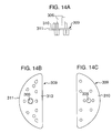
- a filter holding member 309 for holding the dust preventing filter 304 and defining the above-mentioned communication pipe 306 is formed as shown in Fig. 14, and the peripheral surface 311 of an attaching flange part 310 thereof is fitted in the inner peripheral surface 312 of the canister casing 301, as shown in Fig. 13, while the adsorbent side filter 307 is located underneath the filter holding member and welded to the canister casing 301 so as to support the dust preventing filter 304 by the adsorbent side filter 307.
- an object of the present invention is to provide a canister which can aim at restraining clogging of the filter by dust as mentioned above, and at preventing the filter holding member 309 from dropping as mentioned above, in order to enhance the assembling ability thereof.
- a canister comprising a canister casing having at an upper part therein an atmospheric port, the atmospheric port being communicated with an adsorbent filled chamber in the canister casing through the intermediary of a filter mounting chamber containing a filter holding member holding a dust preventing filter and formed therein with a communication hole formed therein being mounted so that the atmospheric air from the atmospheric port passes through the dust preventing filter from the lower surface to the upper surface, and thereafter flows into the adsorbent filled chamber through the communication hole, and an adsorbent side filter being located and secured underneath the filter holding member thus mounted, characterised by a temporary holding means for temporarily holding in a mounted condition the filter holding member before the adsorbent side filter is assembled.
- the filter holding member for holding the dust preventing filter
- the atmospheric air from the atmospheric port passes through the dust preventing filter from the lower surface to the upper surface, and dust sucked with the atmospheric air, sticks to the lower surface of the dust preventing filter. Accordingly, during vibration of the canister, the dust sticking to the lower surface of the dust preventing canister drops as mentioned above so as to restrain clogging of the dust preventing filter, thereby it is possible to restrain the ventilation resistance of the dust preventing filter from being increased due to sticking of dust.
- the filter holding member can be prevented from being dropped by its dead weight even though the posture of the canister casing is changed after the filter holding member is mounted and before the adsorbent side filter is secured.
- the temporary holding means may be composed of a snap fit portion formed in the filter holding member and a protrusion formed on the inner surface of the filter mounting chamber and adapted to be engaged with the snap fit portion.
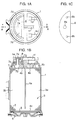
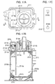
- Fig. 1A is a top view which shows a canister in a first embodiment according to the present invention
- Fig. 1B is a front longitudinal sectional view (in a section A-A) which shows the canister shown in Fig. 1A
- Fig. 1C is a top view which shows a dust filter.
- a cylindrical resin casing 1 defines therein an adsorbent chamber 3 in which adsorbent 2 is filled.
- the adsorbent 2 is held vertically between a first filter 4a, a second filter 4b and a third filter 4c which are welded to the casing 1, and is clamped and pressed by a spring 6 through the intermediary of a retainer plate 5.
- the adsorbent chamber 3 is partitioned into a first adsorbent chamber 3a and a second adsorbent chamber 3b by a partition wall 1a extending downward from the upper part of the casing 1, which are communicated with each other in the lower part of the casing 1.
- a tank port 1c for introducing evaporated fuel from a fuel tank (not shown) during adsorption and a purge port 1d adapted to be communicated with a downstream portion of a throttle valve in an intake pipe of an engine (not shown), for separating evaporated fuel during separation, are opened to an upper space 1b in the first adsorbent chamber 3a. It is noted that the tank port 1c is communicated with the fuel tank by way of a check valve (not shown).
- the first adsorbing chamber 3a is provided in an upper space 1b with a plurality of support parts 1h for supporting the first filter 4a.
- An upper space in the second adsorbent chamber 3b defines therein a filter chamber 1e accommodating and securing therein an adapter 7 formed with a cylindrical pipe 7a standing upright, support portions 7b for supporting the second filter 4b, and support portions 7c for supporting a dust filter 8 which will be hereinbelow described.
- the filter chamber 1e is partitioned by means of a partition wall 1g such that a lower part thereof communicates with the atmosphere via the atmospheric port 1f.
- the dust filter 8 having a crescent-like shape is held in the filter chamber 1e by means of support portions 7c at a substantially vertical center in the filter chamber 1e. It is noted that the reason why the dust filter 8 has a crescent-like shape is based upon such a technical concept that the area of filtering is set in accordance with a flow rate of the atmospheric air so as to cause effective sticking of dust.
- the dust filter 8 is provided substantially at its center with a pipe hole 8a fitted on the pipe 7a, and at opposite ends of the crescent-like shape with pin holes 8b, respectively, fitted on assembly reference pins 7d (two positions). With this arrangement, the filter can be assembled on either the front or rear side thereof.
- the filter chamber 1e is formed in the same shape as that of the dust filter 8 which is therefore fitted therein with no gap.
- the atmospheric air flows and concentrates around the pipe 7a on the lower surface of the dust filter 8, and accordingly, dust or the like in the atmospheric air is not widely distributed over the entire lower surface of the dust filter, and sticks starting from the center part of the filter, thereby it easily drops due to vibration during running of a vehicle, or a gravitational force exerted to the dust or the like.
- the dust filter 218 in the canister shown in Figs. 17A, 17B and 17C has a rectangular shape.
- the dust filter 18' having a pipe hole at substantially a center thereof and a crescent-like shape is used, instead of the rectangular dust filter, and a filter chamber 11c', a cylindrical pipe 11d' expending from the casing 211 and an atmospheric opening port 11e' are used correspondingly to the shape of the filter 18', respectively, so as to prevent the purge volume from deteriorating.
- the explanation thereof is omitted.
- FIG. 3 to 9 there is shown a canister according to the second embodiment of the present invention.
- Fig. 3 is a longitudinal sectional view which shows the canister in such an assembly condition that a filter holding member 35 holding a dust preventing filter 34 is held between an adsorbent filling chamber 32 of the canister casing 31 and an atmospheric chamber 33, and further, an adsorbent side filter 36 is welded
- Fig. 4 is an enlarged sectional view which shows the canister in which mounting parts of the filter holding member 35 and the adsorbent side filter 36 onto the canister casing 31.
- a canister casing 31 which is formed in a cylindrical shape, and is partitioned therein into two adsorbent filling chambers 32, 38 by a partition wall 37 as shown in Figs. 3 and 5, and the adsorbent filling chamber 32, 38 are filled therein with adsorbent made of actived carbon or the like.
- the canister casing 31 is formed in its upper part with an atmospheric port 33, and the upper part of one of the adsorbent chambers 32 defines therein a filter mounting chamber 39.
- the filter mounting chamber 39 being composed of a lower chamber 39a having an inner diameter smaller than that of the adsorbent filling chamber 32 and having a substantially semi-circular shape as viewed in its plan view, and an upper chamber 39b having an inner diameter which is in turn smaller than that of the lower chamber 39a. Further, step portions 39c, 39d are formed between the respective chambers. Furthermore, a vertical wall 40 is formed between an inner opening part 33a of the atmospheric port 33 and the filter mounting chamber 39, and the inner opening part 33a of the atmospheric port 33 is communicated with the filter mounting chamber 39 through a space below the vertical wall 40.
- the canister casing 31 having the above-mentioned components is made of synthetic resin.
- the canister casing 31 is formed with a charge port through which evaporated fuel is sucked from the fuel tank or the like, and a purge port which is communicated with the intake pipe of the engine, and is provided with a bottom cover for covering the lower part of the canister casing 31, as are well-known, but which are omitted.
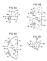
- the above-mentioned filter holding part 35 is composed of a base portion 41 formed of a substantially semicircular plate, an outer peripheral rib 42 downward bent at the outer periphery of the base portion 41, a plurality of leg parts 43 suspended downward from the lower surface of the base portion 41, a plurality of filter holding pillars 44 standing upright on the upper surface of the base portion 41, and a communication pipe 45 standing upright at a substantial center of the based part 41 and formed therein with a communication hole 45a piercing through the base portion 41 from the front surface to the rear surface thereof, which are integrally incorporated with one another and made of resin.
- the lower surface of the outer peripheral rib 42 and the lower surfaces of the leg parts 43 are formed substantially of the same height.
- the outer peripheral surface 41a of the base portion 41 that is, the shape of the outer peripheral surface 41a of the outer peripheral rib 42 is formed in such a way that it can be snugly fitted in the inner peripheral surface 39e of the lower chamber 39a in the filter mounting chamber 39, and the height of the outer peripheral rib 42 is set so as to be substantially equal to the height of the inner peripheral surface 39e.
- a snap fit portion 46 constituting a holding means A is formed in a part of the outer periphery of the base portion 41, being integrally incorporated with the base portion 41.
- the snap fit portion 46 is formed in a U-like shape being projected upward from the lower part of a concave portion 47 which is formed by inwardly bending a part of the outer peripheral rib 42 in a concave shape, and the snap fit portion 46 is resilient so that it is outward projected from the outer peripheral surface 41a of the base portion 41 in a normal configuration thereof, but is retracted into the concave portion 47 by an external force exerted from the outside.
- a locking pawl portion 48 is formed outward at the upper end of the outer surface of the snap fit portion 46.
- the above-mentioned filter holding member 35 supports a dust preventing filter 34 provided at the center thereof with a through-hole 34a which is fitted on the communication pipe 45.
- the dust preventing filter 34 is set at its lower surface on the filter holding pillars 44, and accordingly, a space is defined underneath the dust preventing filter 34.
- the upper end of the communication pipe 45 is slightly projected upward from the upper surface of the dust preventing filter 34.
- the dust preventing filter 34 has a diameter which is set so that the outer peripheral surface of the dust preventing filter 34 is snugly fitted in the inner peripheral surface 39f of the upper chamber 39b in the canister casing 31.
- a protrusion 49 is integrally incorporated with the inner peripheral surface 39e of the lower chamber 39a in the canister casing 31, as shown in Figs. 4 and 5, and the position of the protrusion 49 is set so that the locking pawl portion 48 of the snap fit portion 46 is locked to the upper side of the protrusion 49 when the filter holding member 35 is fitted in the filter mounting chamber 39.
- a filter positioning post 44A adapted to be fitted in another through-hole (which is not shown) in the dust preventing filter 34.
- the dust preventing filter 34 is inserted and held, as shown in Figs. 7A to 7B, in the communication pipe 45 of the filter holding member 35, as shown in Figs. 6A to 6B.
- the canister casing 31 is set in a posture which is vertically reverse to the posture shown in Fig. 5, and the filter holding member 35 which holds the dust preventing filter 34 is inserted as indicated by the arrow shown in Fig. 5, from the opening side of the canister casing 31, and is then fitted in the filter mounting chamber 39 as shown in Fig. 8. Due to this fitting, the locking pawl portion 48 of the snap fit portion 46 which is formed in the filter holding member 35 is locked to the upper side surface of the protrusion 49 due to its stabilizing force after it rides over the protrusion 49 on the canister casing 31, and accordingly, the filter holding member 35 is temporarily held so that it is prevented from dropping by its dead weight.
- the filter holding member 35 can be prevented from dropping by its dead weight even though the canister casing 31 is taken in such a posture, as shown in Fig. 8, that the opening side of the canister casing 31 is directed downward due to convenience for the subsequent process.
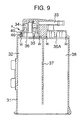
- the adsorbent side filter 36 is made to abut against the step portion 39c of the canister casing 31, and then, the adsorbent side filter 36 is secured to the step portion 39c by means of ultrasonic welding or the like. Accordingly, the filter holding member 35 is fixedly held by the adsorbent side filter 36.
- the above-mentioned welded portion is denoted by W in Fig. 4.
- an adsorbent side filter 36A is secured to the other adsorbent filling chamber 38 by means of ultrasonic welding, similar to that as mentioned above.
- both adsorbent filling chambers 32, 38 are filled therein with adsorbent, and the other components are assembled so as to build up the canister through the well-known process steps.
- the atmospheric air when the atmospheric air is sucked through the atmospheric port 33 during purging, the atmospheric air passes through the dust preventing filter 34 from the lower chamber 39g defined by the dust preventing filter 34, as shown in Fig. 3, and then, flows into the absorbent layer filled in the adsorbent filling chamber 32 after passing through the upper chamber 39h, the through-hole 45a in the communication pipe 45 and the adsorbent side filter 36.
- Fig. 10 shows a third embodiment, in which the snap fit portion 46 in the second embodiment is modified into a locking piece 50 having no locking pawl part 48, and constituting temporarily holding means A. Further, no protrusion 49 is formed in the canister casing 31.
- the outer surface of the locking piece 50 has a diameter which is larger than the inner diameter of the inner peripheral surface 39e in the lower chamber 39a of the canister casing 31, as indicated by the chain line 50a in Fig. 10, and is adapted to be resiliently deformed, as indicated by the solid line in Fig. 10, by a force exerted from the outside.
- the locking piece 50 of the filter holding member 35 is pressed inward so as to be deformed, as indicated by the solid line, by the inner peripheral surface 39e of the lower chamber 39a, and accordingly, the outer surface thereof is made into press-contact with the inner peripheral surface 39e by the stabilizing force of the locking piece 50.
- the filter holding member 35 is temporarily held in the canister casing 31 so as to be prevented from dropping. Accordingly, similar to the above-mentioned second embodiment, it is possible to prevent the filter holding member 35 from dropping.
- Fig. 11 shows a fourth embodiment.
- a protrusion 49 similar to that in the above-mentioned second embodiment is formed on the canister casing 31, but no snap fit portion 46 explained in the second embodiment is formed on the filter holding member 35. That is, the relationship between the outer surface of the outer peripheral rib 42 of the filter folding member 35 and the protrusion 49 in the second embodiment is set so that the outer peripheral rib 42 and the protrusion 49 are made into press-contact with each other in a manner that the filter holding member 35 is prevented from dropping by its dead weight when the filter holding member 35 is inserted in the filter mounting chamber 39. With this arrangement, the temporary holding means A can be obtained. Even in this arrangement, similar to the second embodiment, it is possible to prevent the filter holding member 35 from dropping.
- the other structure, the attachment of the adsorbent side filter 36 and so forth in the fourth embodiment are similar to those in the second embodiment.
- Fig. 12 shows a fifth embodiment.
- a filter holding member 35 having no outer peripheral rib 42 as explained in the second embodiment, that is, the filter holding member shown in Figs. 13 to 15 is used so as to prevent dropping thereof.
- a protrusion 49 similar to that explained in the second embodiment is formed on the canister casing 31.
- the other structure, the attachment of the adsorbent side filter 36 and so forth in the fifth embodiment are similar to those in the second embodiment.
- the dust preventing filter may have a crescent-like shape as explained in the first embodiment.
- the present invention is devised as mentioned above, and therefore, according to the first aspect of the present invention, the ventilation resistance of the dust preventing filter can be prevented from being increased, thereby preventing the purge volume of the canister from being lowered.
- the filter holding member can be prevented from being dropped by its dead weight even though the posture of the canister casing is changed before the process step of securing the adsorbent side filter after the filter holding member is fitted in the canister casing. Thereby, it is possible to aim at enhancing the assembling ability of the canister.
- the temporary holding member is composed of the snap fit portion formed in the filter holding member and a protrusion formed on the inner surface of the filter mounting chamber and adapted to be locked thereto with the snap fit portion, thereby it is possible to ensure temporary holding of the above-mentioned filter holding member.
Landscapes
- Engineering & Computer Science (AREA)
- Chemical & Material Sciences (AREA)
- Combustion & Propulsion (AREA)
- Mechanical Engineering (AREA)
- General Engineering & Computer Science (AREA)
- Supplying Secondary Fuel Or The Like To Fuel, Air Or Fuel-Air Mixtures (AREA)
Abstract
Description
- The present invention relates to a canister for processing evaporated fuel generated in a fuel system in an automobile, so as to adsorb and separate the evaporated fuel, and in particular to a canister having a structure such that dust entering from the atmosphere into the canister is removed during separation of evaporated fuel from the canister, and that the ventilation resistance of a dust filter is restrained from increasing, and that the ability of attachment of the dust filter is enhanced during assembly.
- Heretofore, in an automobile, there has been used an evaporated fuel disposal device for preventing emission of evaporated fuel from a fuel system including a fuel tank into the atmosphere, and there has been well-known a canister as means for adsorbing the evaporated fuel.
- As shown in Fig. 16, such a conventional canister generally includes a
filter 104 provided between anadsorbent layer 102 and anatmospheric port 103 within thecanister 101, and during operation of an engine, an intake pipe vacuum is applied to theadsorbent layer 102 to suck the atmospheric air into anatmospheric chamber 105 through theatmospheric port 103, and then, the atmospheric air is introduced into theadsorbent layer 102 through thefilter 104 so as to purge evaporated fuel which is adsorbed to theadsorbent layer 102 together with the atmospheric air into an intake pipe of the engine. Such acanister 101 is disclosed in, for example, JP-A-11-200962. - By the way, in these years, there has been presented such a tendency that the purge volume of a canister is increased in relation to various regulations. Thus, in view of this fact, a large volume of the atmospheric air is introduced into the above-mentioned
canister 101 through theatmospheric port 103, and accordingly, the quantity of dust entering into thecanister 101 becomes larger so that a large quantity of the dust sticks to the upper surface side of thefilter 104, causing thefilter 104 to clog. As a result, there has been raised such a problem that the function of the canister deteriorates largely. - As shown in Figs. 17A to 17C, there has been known such a canister that the filter can be restrained from clogging, in which an adsorbent 212 is charged in a
casing 211 so as to define anadsorbent chamber 213 while theadsorbent chamber 213 is partitioned by means of apartition wall 211a extending from the upper part of thecasing 211 into a firstadsorbent chamber 213a and a secondadsorbent chamber 213b which are communicated in series with each other. - With this arrangement, the first
adsorbent chamber 213a is provided at its upper part with twocheck valves first check valve 214b being opened so as to pass therethrough evaporated fuel flowing from a fuel tank, which is not shown, by way of atank port 211b while thesecond check valve 214a is closed for blocking. Further, apurge port 211f communicated with a downstream side of a throttle valve of an engine intake pipe, which is not shown, is opened in the upper space of the firstadsorbent chamber 213a. - In the lower part of the
casing 211, the adsorbent 212 is held by aretaining plate 216 andfilters spring 215. The secondadsorbent chamber 213b defines in the upper part thereof afilter chamber 211c in which a rectangularplanar dust filter 218 is mounted. Thedust filter 218 is formed in one end part thereof with apipe hole 218a which is fitted on acylindrical pipe 211d extending from the upper part of thecasing 211. - The
dust filter 218 is formed in the other end part thereof with apin hole 218b having the same size as that of thepipe hole 218, at a position having the same distance from the other end thereof, as that of thepipe holes 218a from the one end thereof. Thispin hole 218b is adapted to be fitted on anassembly reference pin 211g extending downward from afilter cap 219. When the evaporated fuel adsorbed to the absorbent 213 is separated, the atmospheric air sucked under vacuum in the intake pipe of the engine, is introduced into thefilter chamber 211c through anatmospheric opening port 211e thereof, and passes through thedust filter 218 from the bottom to the top thereof, and then is sucked into the secondabsorbent chamber 213b after passing through thepipe 211d. At this time, dust and the like contained in the atmospheric air is filtered out by thedust filter 218, thereby it is possible to feed only the cleaned atmospheric air into the secondabsorbent chamber 213b. - However, in the above-mentioned conventional canister, since the
dust filter 218 is rectangular, dust and the like contained in the atmospheric air sticks to the outer surface of thedust filter 218, over the entire surface of thedust filter 218. Accordingly, it is likely to clog thedust filter 218 in the entirety of the latter. Thus, the ventilation resistance of thedust filter 218 becomes larger, resulting in risk of lowering the purge volume when the evaporated fuel is separated from the canister. - Further, in the above-mentioned conventional canister, as shown in Figs. 17A to 17B, the dust filter is fixed to the upper part of the casing, and a cap-like cover is fitted thereon and formed therein with a suction port through which the atmospheric air is fed into the cover from the lower part of the filter, and accordingly, the sealing ability and the productivity are inferior, thereby it has been desired to improve the canister in this regard.
- An object of preferred embodiments of the present invention is to provide a filter structure in which dust and the like contained in the atmospheric air are prevented from sticking to the filter over the entire surface thereof, and accordingly, the filter becomes less clogged, thereby it is possible to avoid the purge volume of the canister from being lowered due to an increase in the ventilation resistance.
- To the end, according to a first aspect of the present invention, there is provided a canister comprising an adsorbent chamber defined in a casing, filled therein with adsorbent, and partitioned by a partition wall into a first adsorbent chamber and a second adsorbent chamber which are communicated in series with each other, a tank port and a purge port opened to an upper space of the first adsorbent chamber, an atmospheric port opened to an upper space of the second adsorbent chamber, and a dust filter interposed between the atmospheric port and the second adsorbent chamber, characterised in that the dust filter has a crescent-like shape, having a pipe hole which is located in its substantially center part and is adapted to be fitted on a pipe extending in a filter chamber, and the filter chamber accommodating the dust filter has a crescent-like shape substantially identical with the shape of the dust filter, and the atmospheric port is opened to the lower surface side of the dust filter.
- As mentioned above, in the first aspect of the present invention, since the dust filter has a crescent-like shape, having the pipe hole located at substantially the center thereof and fitted on the pipe extending from the upper part of the casing, and since the filter chamber accommodating the dust filter has the crescent shape substantially identical with the shape of the dust filter while the atmospheric port is opened to the lower surface as viewed in the gravitational direction, the atmospheric air flows around the pipe by a large volume so that dust or the like is likely to be accumulated around the pipe, but the opposite end parts of the dust filter having the crescent-like shape are narrowed outward so that the flow of the atmospheric air is small, thereby the dust can hardly be accumulated as a whole. Thus, the ventilation resistance of the dust filter can be restrained from being increased, thereby it is possible to prevent the purge volume of the canister from lowering.
- Next, referring to Figs. 13 and 14, we show a structure of a canister that is considered to solve the problems, that is, the conventional canister is inferior in sealing ability and productivity so as to require improvement thereof.
- In the structure shown in Figs. 13 and 14, the atmospheric air sucked through an
atmospheric port 302 formed in the upper part of acanister casing 301, is introduced into anadsorbent layer 308 by way of alower chamber 303, adust preventing filter 304, anupper chamber 305, acommunication pipe 306 and an adsorbent side filter 307 so as to cause dust which is sucked through theatmospheric port 302 with the atmospheric air to stick to the lower surface of thedust preventing filter 304, and thereafter, to allow the dust to drop into thelower chamber 303 due to vibration during running of a vehicle or the like in order to restrain clogging of thedust preventing filter 304. - In such a structure, it may be considered that a
filter holding member 309 for holding thedust preventing filter 304 and defining the above-mentionedcommunication pipe 306 is formed as shown in Fig. 14, and theperipheral surface 311 of an attachingflange part 310 thereof is fitted in the inner peripheral surface 312 of thecanister casing 301, as shown in Fig. 13, while the adsorbent side filter 307 is located underneath the filter holding member and welded to thecanister casing 301 so as to support thedust preventing filter 304 by the adsorbent side filter 307. - However, after this
filter holding member 309 is fitted and before the adsorbent side filter 307 is secured by welding, if the posture of thecanister 301 is taken as shown in Fig. 13 due to convenience for processing, thefilter holding member 309 would drop by its dead weight as shown in Fig. 15 so that the assembly thereof would be impossible. - Accordingly, an object of the present invention is to provide a canister which can aim at restraining clogging of the filter by dust as mentioned above, and at preventing the
filter holding member 309 from dropping as mentioned above, in order to enhance the assembling ability thereof. - Thus, according to a second aspect of the present invention, there is provided a canister comprising a canister casing having at an upper part therein an atmospheric port, the atmospheric port being communicated with an adsorbent filled chamber in the canister casing through the intermediary of a filter mounting chamber containing a filter holding member holding a dust preventing filter and formed therein with a communication hole formed therein being mounted so that the atmospheric air from the atmospheric port passes through the dust preventing filter from the lower surface to the upper surface, and thereafter flows into the adsorbent filled chamber through the communication hole, and an adsorbent side filter being located and secured underneath the filter holding member thus mounted, characterised by a temporary holding means for temporarily holding in a mounted condition the filter holding member before the adsorbent side filter is assembled.
- In the second aspect of the present invention, with the provision of the filter holding member for holding the dust preventing filter, the atmospheric air from the atmospheric port passes through the dust preventing filter from the lower surface to the upper surface, and dust sucked with the atmospheric air, sticks to the lower surface of the dust preventing filter. Accordingly, during vibration of the canister, the dust sticking to the lower surface of the dust preventing canister drops as mentioned above so as to restrain clogging of the dust preventing filter, thereby it is possible to restrain the ventilation resistance of the dust preventing filter from being increased due to sticking of dust.
- Further, during assembling the filter holding member for holding the above-mentioned dust preventing filter, since the filter holding member is temporarily held to the canister casing by the temporary holding means, the filter holding member can be prevented from being dropped by its dead weight even though the posture of the canister casing is changed after the filter holding member is mounted and before the adsorbent side filter is secured.
- In the second aspect of the present invention, the temporary holding means may be composed of a snap fit portion formed in the filter holding member and a protrusion formed on the inner surface of the filter mounting chamber and adapted to be engaged with the snap fit portion.
- With the above-mentioned arrangement, the temporary attachment of the filter holding member can be highly ensured.
- The present invention will now be described, by way of example only, with reference to the following drawings in which:
- Fig. 1A is a top view illustrating a canister according to a first embodiment of the present invention;
- Fig. 1B is a front longitudinal sectional view (in a Section A-A) of a canister according to the first embodiment of the present invention;
- Fig. 1C is a top view illustrating a filter in the canister according to the first embodiment of the present invention;
- Fig. 2A is a plan view illustrating an example of a canister according to the present invention, in which a filter has a crescent-like shape;
- Fig. 2B is a sectional view taken along a line C-C in Fig. 2A;
- Fig. 3 is a longitudinal sectional view illustrating a second embodiment according to the present invention;
- Fig. 4 is an enlarged longitudinal sectional view illustrating a temporary holding part shown in Fig. 3;
- Fig. 5 is a longitudinal sectional view illustrating a filter holding member before it is mounted to a canister casing shown in Fig. 3;
- Figs. 6A to 6D are views illustrating the filter holding member shown in Fig. 3, among which Fig. 6A is a side view, Fig. 6B is a plan view, Fig. 6C is a bottom view and Fig. 6D is an enlarged sectional view taken along a line D-D in Fig. 6B;
- Fig. 7A is a side view illustrating a dust preventing filter before it is held by the filter holding member shown in Fig. 3;
- Fig. 7B is a side view illustrating the filter after it is held by the filter holding member;
- Fig. 8 is a longitudinal section view illustrating the canister in the second embodiment shown in Fig. 3, in which the filter holding member holding the dust preventing filter is mounted but an adsorbent side filter has not yet mounted;
- Fig. 9 is a longitudinal sectional view illustrating the canister in which the adsorbent side filter is mounted in the condition shown in Fig. 8;
- Fig. 10 is an enlarged sectional view illustrating temporary holding means according to a third embodiment of the present invention;
- Fig. 11 is an enlarged sectional view illustrating temporary holding means according to a fourth embodiment of the present invention;
- Fig. 12 is an enlarged sectional view illustrating temporary holding means according to a fifth embodiment of the present invention;
- Fig. 13 is a longitudinal sectional view illustrating a canister having a structure as an example in comparison with the present invention;
- Figs. 14A to 14C are views illustrating a filter holding member shown in Fig. 13, among which Fig. 14A is a side view, Fig. 14B is a plan view and Fig. 14C is a bottom view;
- Fig. 15 is a longitudinal sectional view illustrating a canister shown in Fig. 13, in which the filter holding member drops after it is mounted to the filter holding member;
- Fig. 16 is a longitudinal sectional view illustrating a conventional canister in which an atmospheric port is formed above a filter so as to filter the atmospheric air passing through the filter from the upper part to the bottom part;
- Fig. 17A is a top view illustrating another conventional canister;
- Fig. 17B is a front longitudinal sectional view (in a section B-B) illustrating the canister shown in Fig. 17A; and
- Fig. 17C is a top view illustrating the canister shown in Fig. 17A.
-
- Fig. 1A is a top view which shows a canister in a first embodiment according to the present invention, Fig. 1B is a front longitudinal sectional view (in a section A-A) which shows the canister shown in Fig. 1A, and Fig. 1C is a top view which shows a dust filter. Referring to Figs. 1A to 1C, a cylindrical resin casing 1 defines therein an
adsorbent chamber 3 in which adsorbent 2 is filled. Theadsorbent 2 is held vertically between afirst filter 4a, asecond filter 4b and athird filter 4c which are welded to the casing 1, and is clamped and pressed by aspring 6 through the intermediary of aretainer plate 5. Theadsorbent chamber 3 is partitioned into afirst adsorbent chamber 3a and asecond adsorbent chamber 3b by apartition wall 1a extending downward from the upper part of the casing 1, which are communicated with each other in the lower part of the casing 1. - A
tank port 1c for introducing evaporated fuel from a fuel tank (not shown) during adsorption and apurge port 1d adapted to be communicated with a downstream portion of a throttle valve in an intake pipe of an engine (not shown), for separating evaporated fuel during separation, are opened to an upper space 1b in thefirst adsorbent chamber 3a. It is noted that thetank port 1c is communicated with the fuel tank by way of a check valve (not shown). Thefirst adsorbing chamber 3a is provided in an upper space 1b with a plurality ofsupport parts 1h for supporting thefirst filter 4a. - An upper space in the
second adsorbent chamber 3b defines therein afilter chamber 1e accommodating and securing therein anadapter 7 formed with acylindrical pipe 7a standing upright,support portions 7b for supporting thesecond filter 4b, andsupport portions 7c for supporting adust filter 8 which will be hereinbelow described. Thefilter chamber 1e is partitioned by means of apartition wall 1g such that a lower part thereof communicates with the atmosphere via theatmospheric port 1f. Thedust filter 8 having a crescent-like shape is held in thefilter chamber 1e by means ofsupport portions 7c at a substantially vertical center in thefilter chamber 1e. It is noted that the reason why thedust filter 8 has a crescent-like shape is based upon such a technical concept that the area of filtering is set in accordance with a flow rate of the atmospheric air so as to cause effective sticking of dust. - The
dust filter 8 is provided substantially at its center with apipe hole 8a fitted on thepipe 7a, and at opposite ends of the crescent-like shape withpin holes 8b, respectively, fitted on assembly reference pins 7d (two positions). With this arrangement, the filter can be assembled on either the front or rear side thereof. Thefilter chamber 1e is formed in the same shape as that of thedust filter 8 which is therefore fitted therein with no gap. Accordingly, during separation of evaporated fuel, the atmospheric air flows and concentrates around thepipe 7a on the lower surface of thedust filter 8, and accordingly, dust or the like in the atmospheric air is not widely distributed over the entire lower surface of the dust filter, and sticks starting from the center part of the filter, thereby it easily drops due to vibration during running of a vehicle, or a gravitational force exerted to the dust or the like. - Further, in the conventional technology, the
dust filter 218 in the canister shown in Figs. 17A, 17B and 17C, has a rectangular shape. On the contrary, in the present invention, as shown in Figs. 2A, 2B, the dust filter 18' having a pipe hole at substantially a center thereof and a crescent-like shape is used, instead of the rectangular dust filter, and afilter chamber 11c', acylindrical pipe 11d' expending from thecasing 211 and anatmospheric opening port 11e' are used correspondingly to the shape of the filter 18', respectively, so as to prevent the purge volume from deteriorating. Incidentally, since other components in the modified example are similar to those in the conventional canister, the explanation thereof is omitted. - Next, explanation will be made of a second embodiment with reference to Figs. 3 to 12.
- Referring to Figs. 3 to 9, there is shown a canister according to the second embodiment of the present invention.
- Fig. 3 is a longitudinal sectional view which shows the canister in such an assembly condition that a
filter holding member 35 holding adust preventing filter 34 is held between anadsorbent filling chamber 32 of thecanister casing 31 and anatmospheric chamber 33, and further, anadsorbent side filter 36 is welded, and Fig. 4 is an enlarged sectional view which shows the canister in which mounting parts of thefilter holding member 35 and theadsorbent side filter 36 onto thecanister casing 31. - The structures of the above-mentioned components and a method of assembling thereof will be explained hereinafter.
- A
canister casing 31 which is formed in a cylindrical shape, and is partitioned therein into twoadsorbent filling chambers partition wall 37 as shown in Figs. 3 and 5, and theadsorbent filling chamber canister casing 31 is formed in its upper part with anatmospheric port 33, and the upper part of one of theadsorbent chambers 32 defines therein afilter mounting chamber 39. Thefilter mounting chamber 39 being composed of alower chamber 39a having an inner diameter smaller than that of theadsorbent filling chamber 32 and having a substantially semi-circular shape as viewed in its plan view, and anupper chamber 39b having an inner diameter which is in turn smaller than that of thelower chamber 39a. Further,step portions vertical wall 40 is formed between aninner opening part 33a of theatmospheric port 33 and thefilter mounting chamber 39, and theinner opening part 33a of theatmospheric port 33 is communicated with thefilter mounting chamber 39 through a space below thevertical wall 40. Thecanister casing 31 having the above-mentioned components is made of synthetic resin. - It is noted that the
canister casing 31 is formed with a charge port through which evaporated fuel is sucked from the fuel tank or the like, and a purge port which is communicated with the intake pipe of the engine, and is provided with a bottom cover for covering the lower part of thecanister casing 31, as are well-known, but which are omitted. - The above-mentioned
filter holding part 35, as shown in Fig. 6, is composed of abase portion 41 formed of a substantially semicircular plate, an outerperipheral rib 42 downward bent at the outer periphery of thebase portion 41, a plurality ofleg parts 43 suspended downward from the lower surface of thebase portion 41, a plurality offilter holding pillars 44 standing upright on the upper surface of thebase portion 41, and acommunication pipe 45 standing upright at a substantial center of the basedpart 41 and formed therein with acommunication hole 45a piercing through thebase portion 41 from the front surface to the rear surface thereof, which are integrally incorporated with one another and made of resin. The lower surface of the outerperipheral rib 42 and the lower surfaces of theleg parts 43 are formed substantially of the same height. - Further, the outer
peripheral surface 41a of thebase portion 41, that is, the shape of the outerperipheral surface 41a of the outerperipheral rib 42 is formed in such a way that it can be snugly fitted in the innerperipheral surface 39e of thelower chamber 39a in thefilter mounting chamber 39, and the height of the outerperipheral rib 42 is set so as to be substantially equal to the height of the innerperipheral surface 39e. - Further, a snap
fit portion 46 constituting a holding means A is formed in a part of the outer periphery of thebase portion 41, being integrally incorporated with thebase portion 41. The snapfit portion 46 is formed in a U-like shape being projected upward from the lower part of aconcave portion 47 which is formed by inwardly bending a part of the outerperipheral rib 42 in a concave shape, and the snapfit portion 46 is resilient so that it is outward projected from the outerperipheral surface 41a of thebase portion 41 in a normal configuration thereof, but is retracted into theconcave portion 47 by an external force exerted from the outside. Further, a lockingpawl portion 48 is formed outward at the upper end of the outer surface of the snapfit portion 46. - As shown in Figs. 7A to 7B, the above-mentioned
filter holding member 35 supports adust preventing filter 34 provided at the center thereof with a through-hole 34a which is fitted on thecommunication pipe 45. Thedust preventing filter 34 is set at its lower surface on thefilter holding pillars 44, and accordingly, a space is defined underneath thedust preventing filter 34. Further, the upper end of thecommunication pipe 45 is slightly projected upward from the upper surface of thedust preventing filter 34. Moreover, thedust preventing filter 34 has a diameter which is set so that the outer peripheral surface of thedust preventing filter 34 is snugly fitted in the innerperipheral surface 39f of theupper chamber 39b in thecanister casing 31. - A
protrusion 49 is integrally incorporated with the innerperipheral surface 39e of thelower chamber 39a in thecanister casing 31, as shown in Figs. 4 and 5, and the position of theprotrusion 49 is set so that the lockingpawl portion 48 of the snapfit portion 46 is locked to the upper side of theprotrusion 49 when thefilter holding member 35 is fitted in thefilter mounting chamber 39. - Referring to Figs. 6A to 7B, there is shown a
filter positioning post 44A adapted to be fitted in another through-hole (which is not shown) in thedust preventing filter 34. - Next, explanation will be made of the method of assembling the above-mentioned embodiment.
- At first, the
dust preventing filter 34 is inserted and held, as shown in Figs. 7A to 7B, in thecommunication pipe 45 of thefilter holding member 35, as shown in Figs. 6A to 6B. - Next, the
canister casing 31 is set in a posture which is vertically reverse to the posture shown in Fig. 5, and thefilter holding member 35 which holds thedust preventing filter 34 is inserted as indicated by the arrow shown in Fig. 5, from the opening side of thecanister casing 31, and is then fitted in thefilter mounting chamber 39 as shown in Fig. 8. Due to this fitting, the lockingpawl portion 48 of the snapfit portion 46 which is formed in thefilter holding member 35 is locked to the upper side surface of theprotrusion 49 due to its stabilizing force after it rides over theprotrusion 49 on thecanister casing 31, and accordingly, thefilter holding member 35 is temporarily held so that it is prevented from dropping by its dead weight. Due to this locking, thefilter holding member 35 can be prevented from dropping by its dead weight even though thecanister casing 31 is taken in such a posture, as shown in Fig. 8, that the opening side of thecanister casing 31 is directed downward due to convenience for the subsequent process. - Next, as shown in Fig. 9, the
adsorbent side filter 36 is made to abut against thestep portion 39c of thecanister casing 31, and then, theadsorbent side filter 36 is secured to thestep portion 39c by means of ultrasonic welding or the like. Accordingly, thefilter holding member 35 is fixedly held by theadsorbent side filter 36. The above-mentioned welded portion is denoted by W in Fig. 4. Further, anadsorbent side filter 36A is secured to the otheradsorbent filling chamber 38 by means of ultrasonic welding, similar to that as mentioned above. - Next, both adsorbent filling
chambers - In the canister assembled as mentioned above, when the atmospheric air is sucked through the
atmospheric port 33 during purging, the atmospheric air passes through thedust preventing filter 34 from thelower chamber 39g defined by thedust preventing filter 34, as shown in Fig. 3, and then, flows into the absorbent layer filled in theadsorbent filling chamber 32 after passing through theupper chamber 39h, the through-hole 45a in thecommunication pipe 45 and theadsorbent side filter 36. - At this time, dust sucked with the atmospheric air sticks to the lower surface of the
dust preventing filter 34. Further, the dust thus sticking drops into thelower chamber 39g during vibration, thereby it is possible to prevent clogging of thedust preventing filter 34. - Fig. 10 shows a third embodiment, in which the snap
fit portion 46 in the second embodiment is modified into alocking piece 50 having no lockingpawl part 48, and constituting temporarily holding means A. Further, noprotrusion 49 is formed in thecanister casing 31. - The outer surface of the locking
piece 50 has a diameter which is larger than the inner diameter of the innerperipheral surface 39e in thelower chamber 39a of thecanister casing 31, as indicated by thechain line 50a in Fig. 10, and is adapted to be resiliently deformed, as indicated by the solid line in Fig. 10, by a force exerted from the outside. - Accordingly, similar to the second embodiment, when the
filter holding member 35 which holds thedust preventing filter 34 is inserted in thefilter mounting chamber 39, the lockingpiece 50 of thefilter holding member 35 is pressed inward so as to be deformed, as indicated by the solid line, by the innerperipheral surface 39e of thelower chamber 39a, and accordingly, the outer surface thereof is made into press-contact with the innerperipheral surface 39e by the stabilizing force of the lockingpiece 50. Thus, thefilter holding member 35 is temporarily held in thecanister casing 31 so as to be prevented from dropping. Accordingly, similar to the above-mentioned second embodiment, it is possible to prevent thefilter holding member 35 from dropping. - The other structure, the attachment of the
adsorbent side filter 36 and so forth in the third embodiment are similar to those in the second embodiment. - Fig. 11 shows a fourth embodiment.
- In the fourth embodiment, a
protrusion 49 similar to that in the above-mentioned second embodiment is formed on thecanister casing 31, but no snapfit portion 46 explained in the second embodiment is formed on thefilter holding member 35. That is, the relationship between the outer surface of the outerperipheral rib 42 of thefilter folding member 35 and theprotrusion 49 in the second embodiment is set so that the outerperipheral rib 42 and theprotrusion 49 are made into press-contact with each other in a manner that thefilter holding member 35 is prevented from dropping by its dead weight when thefilter holding member 35 is inserted in thefilter mounting chamber 39. With this arrangement, the temporary holding means A can be obtained. Even in this arrangement, similar to the second embodiment, it is possible to prevent thefilter holding member 35 from dropping. - The other structure, the attachment of the
adsorbent side filter 36 and so forth in the fourth embodiment are similar to those in the second embodiment. - Fig. 12 shows a fifth embodiment.
- In the fifth embodiment, a
filter holding member 35 having no outerperipheral rib 42 as explained in the second embodiment, that is, the filter holding member shown in Figs. 13 to 15 is used so as to prevent dropping thereof. Referring to Fig. 12, aprotrusion 49 similar to that explained in the second embodiment, is formed on thecanister casing 31. With this arrangement, when thefilter holding member 35 is inserted in thefilter mounting chamber 39, an attachingflange 51 of thefilter holding member 35 rides over theprotrusion 49, and is then locked to the upper surface of theprotrusion 49 as shown in Fig. 12 so as to serve as the temporary holding member A which can temporarily hold thefilter holding member 35, thereby preventing thefilter holding member 35 from dropping by its dead weight. - The other structure, the attachment of the
adsorbent side filter 36 and so forth in the fifth embodiment are similar to those in the second embodiment. - It is noted that in the embodiments subsequent to the second embodiment, the dust preventing filter may have a crescent-like shape as explained in the first embodiment.
- The present invention is devised as mentioned above, and therefore, according to the first aspect of the present invention, the ventilation resistance of the dust preventing filter can be prevented from being increased, thereby preventing the purge volume of the canister from being lowered.
- Further, according to the second aspect of the present invention, it is possible to prevent dust sucked through the atmospheric port from increasing the ventilation resistance of the dust preventing filter. Further, with the provision of the temporary holding means for the filter holding member which holds the dust preventing filter, as mentioned above, the filter holding member can be prevented from being dropped by its dead weight even though the posture of the canister casing is changed before the process step of securing the adsorbent side filter after the filter holding member is fitted in the canister casing. Thereby, it is possible to aim at enhancing the assembling ability of the canister.
- Further, according to the second aspect of the present invention, the temporary holding member is composed of the snap fit portion formed in the filter holding member and a protrusion formed on the inner surface of the filter mounting chamber and adapted to be locked thereto with the snap fit portion, thereby it is possible to ensure temporary holding of the above-mentioned filter holding member.
Claims (4)
- A canister comprising a casing, an adsorbent chamber defined in the casing, filled therein with adsorbent, and partitioned by a partition wall into a first adsorbent chamber and a second adsorbent chamber which are communicated in series with each other, a tank port and a purge port opened to an upper space in the first adsorbent chamber, an atmospheric port opened to an upper space in the second adsorbent chamber, and a dust filter located between the atmospheric port and the second adsorbent chamber, characterised in that the dust filter is formed in a crescent-like shape, having a pipe hole adapted to be fitted on a pipe extended to a filter chamber, at a substantial center thereof, the filter chamber accommodating therein the dust filter is formed in a crescent-like shape substantilly equal to the crescent-like shape of the dust filter, and the atmospheric port is opened to a lower surface side of the dust filter.
- A canister comprising a canister casing having at an upper portion therein an atmospheric port and defining therein with an adsorbent filled chamber, a filter mounting chamber communicating the adsorbent chamber defined in the canister casing with the atmospheric port, and a filter holding member formed therein, for holding a dust preventing filter, with a communication hole and fitted in the filter mounting chamber, the atmospheric air introduced through the atmospheric port flowing into the adsorbent chamber through the communication hole after passing through the dust preventing filter from the lower surface to the upper surface, and an adsorbent side filter is arranged and secured on the bottom side of the fitted filter holding member, characterised by temporary holding means for temporarily holding the filter holding member in a mounted condition before the adsorbent side filter is assembled, between the filter holding member and an inner surface of the filter mounting chamber in which the filter holding member is fitted.
- A canister as set forth in claim 2, characterised in that the temporary holding means is composed of a snap fit portion formed in the filter holding member and a protrusion formed on the inner surface of the filter mounting chamber, in a manner to lock the snap fit portion with the protrusion.
- A canister as set forth in claim 2, characterised in that the dust preventing filter is formed in a crescent-like shape, having a pipe hole fitted on a pipe extended to the filter chamber, at a substantially center thereof, and the filter chamber accommodating therein the dust filter is formed in a crescent-like shape substantially identical with that of the dust filter.
Applications Claiming Priority (4)
| Application Number | Priority Date | Filing Date | Title |
|---|---|---|---|
| JP2000137911 | 2000-05-11 | ||
| JP2000137911A JP2001317418A (en) | 2000-05-11 | 2000-05-11 | Canister |
| JP2000180576 | 2000-05-12 | ||
| JP2000180576A JP2001323846A (en) | 2000-05-12 | 2000-05-12 | Canister |
Publications (2)
| Publication Number | Publication Date |
|---|---|
| EP1154145A2 true EP1154145A2 (en) | 2001-11-14 |
| EP1154145A3 EP1154145A3 (en) | 2003-02-26 |
Family
ID=26591647
Family Applications (1)
| Application Number | Title | Priority Date | Filing Date |
|---|---|---|---|
| EP01304197A Withdrawn EP1154145A3 (en) | 2000-05-11 | 2001-05-10 | Canister |
Country Status (1)
| Country | Link |
|---|---|
| EP (1) | EP1154145A3 (en) |
Cited By (2)
| Publication number | Priority date | Publication date | Assignee | Title |
|---|---|---|---|---|
| US6959698B2 (en) | 2001-06-26 | 2005-11-01 | Toyo Roki Seizo Kabushiki Kaisha | Fuel treating canister |
| CN115217679A (en) * | 2021-04-16 | 2022-10-21 | 双叶产业株式会社 | Filtering tank |
Citations (1)
| Publication number | Priority date | Publication date | Assignee | Title |
|---|---|---|---|---|
| JPH11200962A (en) | 1998-01-06 | 1999-07-27 | Nissan Motor Co Ltd | Canister |
Family Cites Families (13)
| Publication number | Priority date | Publication date | Assignee | Title |
|---|---|---|---|---|
| US3683597A (en) * | 1970-09-17 | 1972-08-15 | Gen Motors Corp | Evaporation loss control |
| US4058380A (en) * | 1973-03-02 | 1977-11-15 | Ford Motor Company | Carbon cell |
| JPS55127123A (en) * | 1979-03-22 | 1980-10-01 | Hitachi Ltd | Evaporated fuel trapper |
| US4598686A (en) * | 1985-03-28 | 1986-07-08 | Casco Products Inc. | Fuel vapor recovery system for automotive vehicles |
| US4852761A (en) * | 1988-07-25 | 1989-08-01 | General Motors Corporation | In tank vapor storage canister |
| JPH02102358A (en) * | 1988-10-11 | 1990-04-13 | Aisan Ind Co Ltd | Canister for fuel evaporated absorption |
| US5641344A (en) * | 1994-12-05 | 1997-06-24 | Tsuchiya Mfg., Co., Ltd. | Fuel vapor treatment device |
| JPH094525A (en) * | 1995-06-22 | 1997-01-07 | Aisan Ind Co Ltd | Evaporative fuel treatment system for vehicles |
| JPH09209849A (en) * | 1996-02-09 | 1997-08-12 | Aisan Ind Co Ltd | Evaporative fuel collection device when refueling a vehicle |
| DE19644610A1 (en) * | 1996-10-26 | 1998-04-30 | Bosch Gmbh Robert | Tank ventilation device for motor vehicles |
| JP3337935B2 (en) * | 1997-02-13 | 2002-10-28 | 愛三工業株式会社 | Canister |
| DE19709781A1 (en) * | 1997-03-10 | 1998-09-17 | Bosch Gmbh Robert | Automotive fuel filter |
| JP3610757B2 (en) * | 1998-01-06 | 2005-01-19 | 日産自動車株式会社 | Canister |
-
2001
- 2001-05-10 EP EP01304197A patent/EP1154145A3/en not_active Withdrawn
Patent Citations (1)
| Publication number | Priority date | Publication date | Assignee | Title |
|---|---|---|---|---|
| JPH11200962A (en) | 1998-01-06 | 1999-07-27 | Nissan Motor Co Ltd | Canister |
Cited By (2)
| Publication number | Priority date | Publication date | Assignee | Title |
|---|---|---|---|---|
| US6959698B2 (en) | 2001-06-26 | 2005-11-01 | Toyo Roki Seizo Kabushiki Kaisha | Fuel treating canister |
| CN115217679A (en) * | 2021-04-16 | 2022-10-21 | 双叶产业株式会社 | Filtering tank |
Also Published As
| Publication number | Publication date |
|---|---|
| EP1154145A3 (en) | 2003-02-26 |
Similar Documents
| Publication | Publication Date | Title |
|---|---|---|
| EP0142095B1 (en) | Accumulator-dehydrator assembly for an air conditioning system | |
| US5119791A (en) | Vapor storage canister with liquid trap | |
| JP4142914B2 (en) | Evaporative fuel processing equipment | |
| US5641344A (en) | Fuel vapor treatment device | |
| JPH07139442A (en) | Canister | |
| JPH07139441A (en) | Canister | |
| US4758255A (en) | Canister for adsorbing fuel vapors | |
| US20030066427A1 (en) | Air cleaner | |
| CN112240256B (en) | Adsorption tank | |
| JPH08114159A (en) | Canister | |
| CN115217679B (en) | Filter pot | |
| CN114109663A (en) | Filtering tank | |
| US7455054B2 (en) | Canister with fuel gas reducing device | |
| JPH08270513A (en) | Canister | |
| EP0935990B1 (en) | Filter apparatus for canister | |
| JP2003003915A (en) | Evaporative fuel treatment canister | |
| KR102582474B1 (en) | A lower cap for dust collector filter and cartridge filter having that lower cap | |
| EP1108883A2 (en) | Fuel supply system | |
| US7717476B2 (en) | End structure for an air intake pipe | |
| JP2001317418A (en) | Canister | |
| KR101336468B1 (en) | Filtration device for use with a fuel vapor recovery system | |
| JP3610757B2 (en) | Canister | |
| JP2001323846A (en) | Canister | |
| JPH0335875Y2 (en) | ||
| JP7196024B2 (en) | canister |
Legal Events
| Date | Code | Title | Description |
|---|---|---|---|
| PUAI | Public reference made under article 153(3) epc to a published international application that has entered the european phase |
Free format text: ORIGINAL CODE: 0009012 |
|
| 17P | Request for examination filed |
Effective date: 20010530 |
|
| AK | Designated contracting states |
Kind code of ref document: A2 Designated state(s): AT BE CH CY DE DK ES FI FR GB GR IE IT LI LU MC NL PT SE TR |
|
| AX | Request for extension of the european patent |
Free format text: AL;LT;LV;MK;RO;SI |
|
| PUAL | Search report despatched |
Free format text: ORIGINAL CODE: 0009013 |
|
| AK | Designated contracting states |
Kind code of ref document: A3 Designated state(s): AT BE CH CY DE DK ES FI FR GB GR IE IT LI LU MC NL PT SE TR Designated state(s): AT BE CH CY DE DK ES FI FR GB GR IE IT LI LU MC NL PT SE TR |
|
| AX | Request for extension of the european patent |
Extension state: AL LT LV MK RO SI |
|
| AKX | Designation fees paid |
Designated state(s): DE FR GB |
|
| STAA | Information on the status of an ep patent application or granted ep patent |
Free format text: STATUS: THE APPLICATION IS DEEMED TO BE WITHDRAWN |
|
| 18D | Application deemed to be withdrawn |
Effective date: 20060427 |