EP1154113A2 - Vehicle pivoting closure power operating assembly - Google Patents
Vehicle pivoting closure power operating assembly Download PDFInfo
- Publication number
- EP1154113A2 EP1154113A2 EP01201662A EP01201662A EP1154113A2 EP 1154113 A2 EP1154113 A2 EP 1154113A2 EP 01201662 A EP01201662 A EP 01201662A EP 01201662 A EP01201662 A EP 01201662A EP 1154113 A2 EP1154113 A2 EP 1154113A2
- Authority
- EP
- European Patent Office
- Prior art keywords
- rack
- pivot axis
- axis
- hinge
- engaged
- Prior art date
- Legal status (The legal status is an assumption and is not a legal conclusion. Google has not performed a legal analysis and makes no representation as to the accuracy of the status listed.)
- Granted
Links
Images


Classifications
-
- B—PERFORMING OPERATIONS; TRANSPORTING
- B60—VEHICLES IN GENERAL
- B60J—WINDOWS, WINDSCREENS, NON-FIXED ROOFS, DOORS, OR SIMILAR DEVICES FOR VEHICLES; REMOVABLE EXTERNAL PROTECTIVE COVERINGS SPECIALLY ADAPTED FOR VEHICLES
- B60J5/00—Doors
- B60J5/10—Doors arranged at the vehicle rear
- B60J5/101—Doors arranged at the vehicle rear for non-load transporting vehicles, i.e. family cars including vans
- B60J5/105—Doors arranged at the vehicle rear for non-load transporting vehicles, i.e. family cars including vans comprising door or part of door being pivotable about vertical axis
-
- E—FIXED CONSTRUCTIONS
- E05—LOCKS; KEYS; WINDOW OR DOOR FITTINGS; SAFES
- E05F—DEVICES FOR MOVING WINGS INTO OPEN OR CLOSED POSITION; CHECKS FOR WINGS; WING FITTINGS NOT OTHERWISE PROVIDED FOR, CONCERNED WITH THE FUNCTIONING OF THE WING
- E05F15/00—Power-operated mechanisms for wings
- E05F15/60—Power-operated mechanisms for wings using electrical actuators
- E05F15/603—Power-operated mechanisms for wings using electrical actuators using rotary electromotors
- E05F15/611—Power-operated mechanisms for wings using electrical actuators using rotary electromotors for swinging wings
- E05F15/616—Power-operated mechanisms for wings using electrical actuators using rotary electromotors for swinging wings operated by push-pull mechanisms
- E05F15/619—Power-operated mechanisms for wings using electrical actuators using rotary electromotors for swinging wings operated by push-pull mechanisms using flexible or rigid rack-and-pinion arrangements
-
- E—FIXED CONSTRUCTIONS
- E05—LOCKS; KEYS; WINDOW OR DOOR FITTINGS; SAFES
- E05F—DEVICES FOR MOVING WINGS INTO OPEN OR CLOSED POSITION; CHECKS FOR WINGS; WING FITTINGS NOT OTHERWISE PROVIDED FOR, CONCERNED WITH THE FUNCTIONING OF THE WING
- E05F15/00—Power-operated mechanisms for wings
- E05F15/60—Power-operated mechanisms for wings using electrical actuators
- E05F15/603—Power-operated mechanisms for wings using electrical actuators using rotary electromotors
- E05F15/611—Power-operated mechanisms for wings using electrical actuators using rotary electromotors for swinging wings
- E05F15/63—Power-operated mechanisms for wings using electrical actuators using rotary electromotors for swinging wings operated by swinging arms
-
- E—FIXED CONSTRUCTIONS
- E05—LOCKS; KEYS; WINDOW OR DOOR FITTINGS; SAFES
- E05Y—INDEXING SCHEME ASSOCIATED WITH SUBCLASSES E05D AND E05F, RELATING TO CONSTRUCTION ELEMENTS, ELECTRIC CONTROL, POWER SUPPLY, POWER SIGNAL OR TRANSMISSION, USER INTERFACES, MOUNTING OR COUPLING, DETAILS, ACCESSORIES, AUXILIARY OPERATIONS NOT OTHERWISE PROVIDED FOR, APPLICATION THEREOF
- E05Y2201/00—Constructional elements; Accessories therefor
- E05Y2201/40—Motors; Magnets; Springs; Weights; Accessories therefor
- E05Y2201/43—Motors
- E05Y2201/434—Electromotors; Details thereof
-
- E—FIXED CONSTRUCTIONS
- E05—LOCKS; KEYS; WINDOW OR DOOR FITTINGS; SAFES
- E05Y—INDEXING SCHEME ASSOCIATED WITH SUBCLASSES E05D AND E05F, RELATING TO CONSTRUCTION ELEMENTS, ELECTRIC CONTROL, POWER SUPPLY, POWER SIGNAL OR TRANSMISSION, USER INTERFACES, MOUNTING OR COUPLING, DETAILS, ACCESSORIES, AUXILIARY OPERATIONS NOT OTHERWISE PROVIDED FOR, APPLICATION THEREOF
- E05Y2201/00—Constructional elements; Accessories therefor
- E05Y2201/60—Suspension or transmission members; Accessories therefor
- E05Y2201/622—Suspension or transmission members elements
- E05Y2201/71—Toothed gearing
- E05Y2201/722—Racks
-
- E—FIXED CONSTRUCTIONS
- E05—LOCKS; KEYS; WINDOW OR DOOR FITTINGS; SAFES
- E05Y—INDEXING SCHEME ASSOCIATED WITH SUBCLASSES E05D AND E05F, RELATING TO CONSTRUCTION ELEMENTS, ELECTRIC CONTROL, POWER SUPPLY, POWER SIGNAL OR TRANSMISSION, USER INTERFACES, MOUNTING OR COUPLING, DETAILS, ACCESSORIES, AUXILIARY OPERATIONS NOT OTHERWISE PROVIDED FOR, APPLICATION THEREOF
- E05Y2800/00—Details, accessories and auxiliary operations not otherwise provided for
- E05Y2800/20—Combinations of elements
- E05Y2800/242—Combinations of elements arranged in parallel relationship
-
- E—FIXED CONSTRUCTIONS
- E05—LOCKS; KEYS; WINDOW OR DOOR FITTINGS; SAFES
- E05Y—INDEXING SCHEME ASSOCIATED WITH SUBCLASSES E05D AND E05F, RELATING TO CONSTRUCTION ELEMENTS, ELECTRIC CONTROL, POWER SUPPLY, POWER SIGNAL OR TRANSMISSION, USER INTERFACES, MOUNTING OR COUPLING, DETAILS, ACCESSORIES, AUXILIARY OPERATIONS NOT OTHERWISE PROVIDED FOR, APPLICATION THEREOF
- E05Y2900/00—Application of doors, windows, wings or fittings thereof
- E05Y2900/50—Application of doors, windows, wings or fittings thereof for vehicles
- E05Y2900/53—Type of wing
- E05Y2900/531—Doors
- E05Y2900/532—Back doors or end doors
-
- E—FIXED CONSTRUCTIONS
- E05—LOCKS; KEYS; WINDOW OR DOOR FITTINGS; SAFES
- E05Y—INDEXING SCHEME ASSOCIATED WITH SUBCLASSES E05D AND E05F, RELATING TO CONSTRUCTION ELEMENTS, ELECTRIC CONTROL, POWER SUPPLY, POWER SIGNAL OR TRANSMISSION, USER INTERFACES, MOUNTING OR COUPLING, DETAILS, ACCESSORIES, AUXILIARY OPERATIONS NOT OTHERWISE PROVIDED FOR, APPLICATION THEREOF
- E05Y2900/00—Application of doors, windows, wings or fittings thereof
- E05Y2900/50—Application of doors, windows, wings or fittings thereof for vehicles
- E05Y2900/53—Type of wing
- E05Y2900/546—Tailboards, tailgates or sideboards opening upwards
Definitions
- the present invention relates to a vehicle pivoting closure, and more particularly to a remotely actuated vehicle pivoting closure power operating assembly for a liftgate.
- Pivoting closures, tailgates and more specifically, liftgates, of vehicles, such as mini-vans, sport utility vehicles and the like, are hinged generally along one edge or cut line.
- the cut line forms the seam between the exterior surface of the closure and the exterior surface of the vehicle body.
- the closure pivots, at the top along a substantially horizontal hinge axis.
- the hinge axis may be disposed interiorly from the cut line or exteriorly from the cut line with respect to the vehicle. If the cut line is interior or inside of the cut line, a "goose-neck" hinge is typically used so the closure can clear the vehicle structure when it pivots open and closed.
- Liftgates are known to have a horizontal hinge axis disposed interiorly to the cut line utilizing a goose-neck hinge.
- the liftgate goose-neck hinges are pivotally engaged to the roof of the vehicle or header of the rear opening which is generally supported on either side by a substantially vertical D-pillar.
- Manually operating the liftgate requires a fair amount of human strength to lift the gate up when opening, or to pull the liftgate down when closing.
- Gas Struts are commonly used to provide assistance in the lifting of the liftgate, however, they resist the pulling down or closing of the liftgate.
- the liftgate can be hard to reach for users of a short stature.
- Electrically powered actuators are known to open and close pivoting closures or liftgates. These actuators vary from hydraulic cylinders to cable assemblies. Placement of the assemblies within the vehicle are limited due to the concentrated forces applied by the mechanisms to the vehicle structure. One means of reducing the concentrated loads is to secure the powered actuators or assemblies to the closure at some considerable distance away from the hinge axis.
- Pinion gear driven rack assemblies typically engage between the vertical D-pillars of the vehicle and the closure by pivoting rods which push or pull upon the liftgate independent of the liftgate goose-neck hinges and at a considerable distance away from the hinge axis. Consequently, the D-pillar support rack designs visibly protrude into the opening of the cargo bay.
- a vehicle pivoting closure assembly has a power actuator remotely controlled by a controller for opening and closing a closure, preferably a liftgate, over a cargo opening.
- the closure is pivotally engaged to a vehicle structure by a hinge member about a hinge axis.
- the hinge member has a first portion which extends from the hinge axis to a secondary pivot axis.
- a second portion of the hinge member rigidly extends from the first portion near the secondary pivot axis and engages the closure at its distal end.
- An armature interconnects a linear moving rack to the hinge member by pivotally engaging the hinge member about the secondary pivot axis, and pivotally engaging the rack at an opposite end about a rack pivot axis.
- the hinge axis, the secondary pivot axis and the rack pivot axis are disposed parallel to one another.
- the elongated rack slides transversely with respect to the hinge axis, moving preferably within a housing secured to the vehicle structure.
- a pinion gear train engages teeth formed on the rack to produce the linear movement.
- the gear train rotates about a rotational axis preferably disposed perpendicular to the rack pivoting axis.
- the gear train is preferably powered by an electric motor through a clutch.
- the power actuator is preferably in modular form having tray which supports the rack housing, the gear train, the motor, and the clutch. The tray also reinforces the pivoting connection of the hinge member, thereby containing the concentrated loads, or dynamic forces, placed upon the hinge member by the motor within the tray, and further distributing the reactive forces produced by the weight of the door through the vehicle structure, or body.
- a feature of the invention is the remotely controlled and powered opening and closing of a vehicle closure.
- the power actuator has a low profile and does not intrude upon the interior space or cargo area of the vehicle.
- Yet another feature of the invention is the ability to conceal the power actuator for aesthetic advantages.
- Still another feature of the invention is that the power actuator is modular in form and has fewer parts and is less complicated than other operating systems.
- Still yet another feature of the invention is the isolation or containment of dynamic forces from the vehicle structure during closing and opening of the liftgate, thereby, protecting the vehicle structure from damage at the hinge mounting locations.
- FIGS. 1 and 2 show a vehicle 10 having a pivoting closure assembly 11 in an open position.
- a closure 12 of the assembly 11 may be any form of door pivoting in any direction, but is preferably a liftgate capable of closing pivotally upon a cargo opening 13.
- At least one goose-neck hinge member 18 engages rigidly to the closure 12 and pivotally to the header of the opening 13 or vehicle roof 14.
- the opening 13 is defined, in part, by the header or roof 14 and two roof supporting, substantially vertical, D-pillars 15 located on either end of the header.
- the hinge members 18 pivot about a common, substantially horizontal, hinge axis 24 disposed interiorly to a seam or cut-line 17 generally defining the perimeter of the opening 13 at the exterior surface of the vehicle 10.
- Mounted to the vehicle roof 14 is a power actuator 16 of the closure assembly 11 engaged operatively to the closure 12 via the hinge member 18.
- An electric controller 20 for the power actuator 16 is mounted remotely from the closure 12 and preferably conveniently next to the driver area of the vehicle 10.
- the power actuator 16 has a low profile enabling concealment beneath the interior surface or headliner of the vehicle.
- the hinge member 18 has an elongated first portion 22 concealed within the power actuator 16. The first portion 22 extends from the hinge axis 24 to a secondary pivot pin or axis 26 not found on a common manual hinge. The first portion 22 of the hinge member 18 pivots about the hinge axis 24 which is stationary with respect to the vehicle structure or roof 14.
- the power actuator 16 includes a tray 27 for pivotally engaging the hinge member 18 at the hinge axis 24, thereby reinforcing the roof 14.
- the tray 27 provides a means to distribute the otherwise concentrated loads exerted upon the roof 14 by the hinge member 18 as a result of forces exerted by the power acutator 16 directly to the hinge member 18.
- Most liftgates can be operated with one power actuator by virtue of tray 27.
- the shape of the hinge member 18 substantially resembles a "goose-neck" or an inverted “question mark.”
- the elongated first portion 22 is substantially straight.
- the remaining or second portion 28 of the hinge member 18 is curved and is substantially larger than the first portion 22.
- the second portion 28 rigidly extends from the distal end of the first portion 22 substantially near the secondary pivot axis 26.
- the second portion 28 has a straight portion 29 at its own opposite distal end that is attached to closure 12 by a plurality of fasteners or bolts (not shown).
- a link or armature 30 linking the hinge member 18 to an elongated rack 32, as best shown in Figure. 5.
- the rack 32 is disposed substantially horizontal, forward of the hinge member 18 in relationship to the vehicle 10 and perpendicular to the hinge axis 24.
- the rack 32 slides linearly and longitudinally within a housing 34 supported by and disposed beneath the tray 27.
- the housing 34 has a longitudinally extending slot 40 disposed on a substantially vertical side 35 of the housing 34 and which communicates through a distal end of the housing 34 closest to the hinge member 18.
- Extending laterally outward from a substantially vertical side 36 of the rack 32 and through the slot 40 is a fin 38.
- the armature 30 pivotally engages the fin 38 at its opposite end pivoting about a rack pivot pin or axis 42.
- the rack pivot axis 42 is parallel to the hinge axis 24 of the hinge member 18 which is parallel to the secondary pivot axis 26.
- an electrical motor 44 which mounts and drives or turns a clutch 46 which transmits the torque to a pinion gear train 48.
- the pinion gear train 48 preferably increases the torque substantially for example by a factor of 5.33:1 and translates the torque to a linear force by engaging vertical extended teeth 50 formed into a side 52 of rack 32 opposite side 36.
- the pinion gear train 48 has a pinion gear 54 which rotates about a pinion gear rotational axis 56 engaging the teeth 50 of the rack 32 causing linear movement of the rack 32.
- the rotational axis 56 is substantially perpendicular to the rack pivot axis 42.
- an intermediate gear 58 of the pinion gear train 48 Engaged concentrically, and preferably unitarily, to the pinion gear 54 is an intermediate gear 58 of the pinion gear train 48.
- the intermediate gear 58 is considerably larger than the pinion gear 54 and consequently is disposed laterally between the rack housing 34 and the tray 26 as best shown in Figure 6.
- Lying within the same imaginary plane as the intermediate gear 58 is a drive gear 60 having a drive gear rotational axis 62 disposed substantially parallel to the pinion gear rotational axis 56.
- the drive gear 60 is rotated by the clutch 46 which is driven by the electric motor 44 upon a signal sent by the controller 20.
- the gear train 48 increases torque substantially as indicated above .
- the drive gear 60 may have nine teeth
- the intermediate gear 58 may have forty-eight teeth
- the pinion gear 54 may have eight teeth for driving the rack 32 in a linear direction toward and away from the hinge axis 24.
- the fin 38 of the rack 32 has a channel 64 traversing the rack pivot axis 42.
- the armature 30 extends pivotally outward from the channel 64.
- a pin or fastener 66 is centered about the rack pivot axis 42 and traverses the channel 64 through the armature 30. While the rack 32 moves rearward toward the liftgate within the housing 34 to open the closure 12, the fin 38 moves rearward along the slot 40, and the armature 30 pivots downward about axis 42 within the channel 64.
- FIG. 7 a second embodiment of the pivoting closure assembly 11'is shown wherein the closure 12' is a tailgate or door which pivots about a hinge axis 24' that is substantially vertical.
- the power actuator 16' which is substantially identical to the power actuator 16 described above, is rotated ninety degrees from the orientation of the first embodiment to align with the vertical hinge axis 24'.
- the power actuator 16' is secured to the D-pillar 15' of the vehicle 10'.
- FIG. 8 and 9 a third embodiment of the pivoting closure assembly 11" is shown.
- the rack 32" moves linearly and substantially horizontally within the housing 34" like the first embodiment, however, the fin 38 of the first embodiment is not required in the third embodiment.
- the armature 30" is engaged pivotally to the leading end of the rack 32" and rides within the same housing 34".
- Housing 34" has a bell shaped end 70 which generally curves upward and provides the necessary clearance for the armature 30" to angle, or pivot, laterally upward as the rack 32" pushes the armature 30" axially out of the housing 34".
- the teeth 50" of the rack 32" are mounted on an adjacent side (relative to the first embodiment), or top side of the rack 32".
- the teeth 50 of the rack 32 may be disposed on the same side 36 as the fin 38.
- the teeth 52 of the rack 32 may be disposed on the upper or lower sides of the rack 32. This positioning would create a ninety degree rotation of the pinion gear train as previously described. It is also understood that the terms used herein are merely descriptive rather than limiting and various changes may be made without departing from the scope and spirit of the invention.
Landscapes
- Engineering & Computer Science (AREA)
- Mechanical Engineering (AREA)
- Power-Operated Mechanisms For Wings (AREA)
- Body Structure For Vehicles (AREA)
Abstract
Description
- The present invention relates to a vehicle pivoting closure, and more particularly to a remotely actuated vehicle pivoting closure power operating assembly for a liftgate.
- Pivoting closures, tailgates and more specifically, liftgates, of vehicles, such as mini-vans, sport utility vehicles and the like, are hinged generally along one edge or cut line. The cut line forms the seam between the exterior surface of the closure and the exterior surface of the vehicle body. For liftgates, the closure pivots, at the top along a substantially horizontal hinge axis. The hinge axis may be disposed interiorly from the cut line or exteriorly from the cut line with respect to the vehicle. If the cut line is interior or inside of the cut line, a "goose-neck" hinge is typically used so the closure can clear the vehicle structure when it pivots open and closed.
- Liftgates are known to have a horizontal hinge axis disposed interiorly to the cut line utilizing a goose-neck hinge. The liftgate goose-neck hinges are pivotally engaged to the roof of the vehicle or header of the rear opening which is generally supported on either side by a substantially vertical D-pillar. Manually operating the liftgate requires a fair amount of human strength to lift the gate up when opening, or to pull the liftgate down when closing. Gas Struts are commonly used to provide assistance in the lifting of the liftgate, however, they resist the pulling down or closing of the liftgate. Furthermore, when fully open, the liftgate can be hard to reach for users of a short stature.
- Electrically powered actuators are known to open and close pivoting closures or liftgates. These actuators vary from hydraulic cylinders to cable assemblies. Placement of the assemblies within the vehicle are limited due to the concentrated forces applied by the mechanisms to the vehicle structure. One means of reducing the concentrated loads is to secure the powered actuators or assemblies to the closure at some considerable distance away from the hinge axis. Pinion gear driven rack assemblies typically engage between the vertical D-pillars of the vehicle and the closure by pivoting rods which push or pull upon the liftgate independent of the liftgate goose-neck hinges and at a considerable distance away from the hinge axis. Consequently, the D-pillar support rack designs visibly protrude into the opening of the cargo bay.
- A vehicle pivoting closure assembly has a power actuator remotely controlled by a controller for opening and closing a closure, preferably a liftgate, over a cargo opening. The closure is pivotally engaged to a vehicle structure by a hinge member about a hinge axis. The hinge member has a first portion which extends from the hinge axis to a secondary pivot axis. A second portion of the hinge member rigidly extends from the first portion near the secondary pivot axis and engages the closure at its distal end. An armature interconnects a linear moving rack to the hinge member by pivotally engaging the hinge member about the secondary pivot axis, and pivotally engaging the rack at an opposite end about a rack pivot axis. The hinge axis, the secondary pivot axis and the rack pivot axis are disposed parallel to one another.
- The elongated rack slides transversely with respect to the hinge axis, moving preferably within a housing secured to the vehicle structure. A pinion gear train engages teeth formed on the rack to produce the linear movement. The gear train rotates about a rotational axis preferably disposed perpendicular to the rack pivoting axis. The gear train is preferably powered by an electric motor through a clutch. The power actuator is preferably in modular form having tray which supports the rack housing, the gear train, the motor, and the clutch. The tray also reinforces the pivoting connection of the hinge member, thereby containing the concentrated loads, or dynamic forces, placed upon the hinge member by the motor within the tray, and further distributing the reactive forces produced by the weight of the door through the vehicle structure, or body.
- A feature of the invention is the remotely controlled and powered opening and closing of a vehicle closure.
- Another feature of the invention is that the power actuator has a low profile and does not intrude upon the interior space or cargo area of the vehicle.
- Yet another feature of the invention is the ability to conceal the power actuator for aesthetic advantages.
- Still another feature of the invention is that the power actuator is modular in form and has fewer parts and is less complicated than other operating systems.
- Still yet another feature of the invention is the isolation or containment of dynamic forces from the vehicle structure during closing and opening of the liftgate, thereby, protecting the vehicle structure from damage at the hinge mounting locations.
- These and other objects, features and advantages of the invention will become more apparent from the following description of the preferred embodiments taken in conjunction with the accompanying drawings.
- The presently preferred embodiments of the invention are disclosed in the following description and in the accompanying drawings wherein:
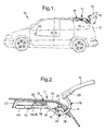
- Figure 1 is a side view of a vehicle having a pivoting closure assembly of the present invention;
- Figure 2 is an enlarged cross section side view of the pivoting closure assembly in an open position;
- Figure 3 is an enlarged cross section side view of the pivoting closure assembly in a closed position;
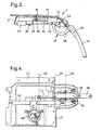
- Figure 4 is a bottom view of a power actuator of the pivoting closure assembly with a motor and a clutch removed to show internal detail;
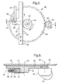
- Figure 5 is an enlarged bottom view of the power actuator with a rack housing and tray removed to show internal detail;
- Figure 6 is a cross section view of the power actuator taken along line 6-6 of Figure 5 viewing in the direction of the arrows;
- Figure 7 is a perspective view of a second embodiment of the pivoting closure assembly;
- Figure 8 is a side view of a third embodiment of the power actuator in a closed position; and
- Figure 9 is the side view of the third embodiment of the power actuator in an open position.
-
- Referring in more detail to the drawings, Figures 1 and 2 show a
vehicle 10 having apivoting closure assembly 11 in an open position. Aclosure 12 of theassembly 11 may be any form of door pivoting in any direction, but is preferably a liftgate capable of closing pivotally upon a cargo opening 13. At least one goose-neck hinge member 18 engages rigidly to theclosure 12 and pivotally to the header of the opening 13 orvehicle roof 14. Theopening 13 is defined, in part, by the header orroof 14 and two roof supporting, substantially vertical, D-pillars 15 located on either end of the header. Thehinge members 18 pivot about a common, substantially horizontal,hinge axis 24 disposed interiorly to a seam or cut-line 17 generally defining the perimeter of theopening 13 at the exterior surface of thevehicle 10. Mounted to thevehicle roof 14 is apower actuator 16 of theclosure assembly 11 engaged operatively to theclosure 12 via thehinge member 18. Anelectric controller 20 for thepower actuator 16 is mounted remotely from theclosure 12 and preferably conveniently next to the driver area of thevehicle 10. - Referring to Figures 2 and 3, the
hinge member 18, which is engaged to thepower actuator 16, externally resembles a common manual liftgate goose-neck hinge. Aesthetically, there is little to no indication that the liftgate orclosure 12 is power actuated at all, or is engaged to the vehicle by anything but a common hinge. Thepower actuator 16 has a low profile enabling concealment beneath the interior surface or headliner of the vehicle. Thehinge member 18 has an elongatedfirst portion 22 concealed within thepower actuator 16. Thefirst portion 22 extends from thehinge axis 24 to a secondary pivot pin oraxis 26 not found on a common manual hinge. Thefirst portion 22 of thehinge member 18 pivots about thehinge axis 24 which is stationary with respect to the vehicle structure orroof 14. When pivoting, thefirst portion 22 forms an approximate ninety degree arc at its opposite end substantially near thesecondary pivot axis 26. Likewise, theclosure 12 pivots within a ninety degree arc with respect to the cargo opening 13. Thepower actuator 16 includes atray 27 for pivotally engaging thehinge member 18 at thehinge axis 24, thereby reinforcing theroof 14. Thetray 27 provides a means to distribute the otherwise concentrated loads exerted upon theroof 14 by thehinge member 18 as a result of forces exerted by thepower acutator 16 directly to thehinge member 18. Most liftgates can be operated with one power actuator by virtue oftray 27. - The shape of the
hinge member 18 substantially resembles a "goose-neck" or an inverted "question mark." The elongatedfirst portion 22 is substantially straight. The remaining orsecond portion 28 of thehinge member 18 is curved and is substantially larger than thefirst portion 22. Thesecond portion 28 rigidly extends from the distal end of thefirst portion 22 substantially near thesecondary pivot axis 26. Thesecond portion 28 has astraight portion 29 at its own opposite distal end that is attached toclosure 12 by a plurality of fasteners or bolts (not shown). - Referring to Figures 2-5, engaging pivotally to the
secondary pivot axis 26 is a link orarmature 30 linking thehinge member 18 to anelongated rack 32, as best shown in Figure. 5. Therack 32 is disposed substantially horizontal, forward of thehinge member 18 in relationship to thevehicle 10 and perpendicular to thehinge axis 24. Therack 32 slides linearly and longitudinally within ahousing 34 supported by and disposed beneath thetray 27. Thehousing 34 has alongitudinally extending slot 40 disposed on a substantially vertical side 35 of thehousing 34 and which communicates through a distal end of thehousing 34 closest to thehinge member 18. Extending laterally outward from a substantiallyvertical side 36 of therack 32 and through theslot 40 is afin 38. Thearmature 30 pivotally engages thefin 38 at its opposite end pivoting about a rack pivot pin oraxis 42. Therack pivot axis 42 is parallel to thehinge axis 24 of thehinge member 18 which is parallel to thesecondary pivot axis 26. - Also disposed beneath and engaged to the
tray 26 is anelectrical motor 44 which mounts and drives or turns a clutch 46 which transmits the torque to apinion gear train 48. Thepinion gear train 48 preferably increases the torque substantially for example by a factor of 5.33:1 and translates the torque to a linear force by engaging verticalextended teeth 50 formed into aside 52 ofrack 32opposite side 36. Referring to Figures 5 and 6, thepinion gear train 48 has apinion gear 54 which rotates about a pinion gearrotational axis 56 engaging theteeth 50 of therack 32 causing linear movement of therack 32. Therotational axis 56 is substantially perpendicular to therack pivot axis 42. Engaged concentrically, and preferably unitarily, to thepinion gear 54 is anintermediate gear 58 of thepinion gear train 48. Theintermediate gear 58 is considerably larger than thepinion gear 54 and consequently is disposed laterally between therack housing 34 and thetray 26 as best shown in Figure 6. Lying within the same imaginary plane as theintermediate gear 58 is adrive gear 60 having a drive gearrotational axis 62 disposed substantially parallel to the pinion gearrotational axis 56. Thedrive gear 60 is rotated by the clutch 46 which is driven by theelectric motor 44 upon a signal sent by thecontroller 20. Preferably thegear train 48 increases torque substantially as indicated above . For instance, thedrive gear 60 may have nine teeth, theintermediate gear 58 may have forty-eight teeth, and thepinion gear 54 may have eight teeth for driving therack 32 in a linear direction toward and away from thehinge axis 24. - Referring to Figures 5 and 6, the
fin 38 of therack 32 has achannel 64 traversing therack pivot axis 42. Thearmature 30 extends pivotally outward from thechannel 64. A pin orfastener 66 is centered about therack pivot axis 42 and traverses thechannel 64 through thearmature 30. While therack 32 moves rearward toward the liftgate within thehousing 34 to open theclosure 12, thefin 38 moves rearward along theslot 40, and thearmature 30 pivots downward aboutaxis 42 within thechannel 64. - Referring to Figure 7, a second embodiment of the pivoting closure assembly 11'is shown wherein the closure 12' is a tailgate or door which pivots about a hinge axis 24' that is substantially vertical. The power actuator 16' which is substantially identical to the
power actuator 16 described above, is rotated ninety degrees from the orientation of the first embodiment to align with the vertical hinge axis 24'. Preferably, the power actuator 16'is secured to the D-pillar 15' of the vehicle 10'. - Referring to Figures 8 and 9, a third embodiment of the pivoting
closure assembly 11" is shown. Therack 32" moves linearly and substantially horizontally within thehousing 34" like the first embodiment, however, thefin 38 of the first embodiment is not required in the third embodiment. Instead, thearmature 30" is engaged pivotally to the leading end of therack 32" and rides within thesame housing 34".Housing 34" has a bell shapedend 70 which generally curves upward and provides the necessary clearance for thearmature 30" to angle, or pivot, laterally upward as therack 32" pushes thearmature 30" axially out of thehousing 34". Furthermore, theteeth 50" of therack 32" are mounted on an adjacent side (relative to the first embodiment), or top side of therack 32". This orientates the pinion gearrotational axis 56" parallel to therack pivot axis 42". Mounted rotationally on both the leading and trailing ends of therack 32" are a pair ofwheels 72 which ride on the inner bottom surface of thehousing 34" for friction reduction between thehousing 34" and therack 32"...hen pivotingclosure assembly 11" is installed in avehicle housing 34" is attached to the vehicle roof so thathinge axis 24" is located interiorly of the cut line shown in Figure 2. The liftgate is then attached to the distal end ofhinge member 18". The vehicle and liftgate are not shown in Figures 8 and 9 since such structure are well known and understood. - Although the preferred embodiments have been disclosed, various changes and modifications may be made thereto by one skilled in the art without departing from the scope and spirit of the invention as set forth in the appended claims. For instance, the
teeth 50 of therack 32 may be disposed on thesame side 36 as thefin 38. Furthermore, for varying space restrictions within thevehicle 10, theteeth 52 of therack 32 may be disposed on the upper or lower sides of therack 32. This positioning would create a ninety degree rotation of the pinion gear train as previously described. It is also understood that the terms used herein are merely descriptive rather than limiting and various changes may be made without departing from the scope and spirit of the invention.
Claims (20)
- An automotive pivoting closure assembly comprising:a vehicle structure;a hinge member having a first portion, a second portion, a hinge axis, and an opposite secondary pivot axis, the first portion engaged pivotally to the vehicle structure about the hinge axis and extended between the hinge axis and secondary pivot axis, the hinge axis remaining stationary to the vehicle structure, the second portion extended rigidly from the first portion at the secondary pivot axis, the hinge axis being parallel to the secondary pivot axis;a closure engaged to the second portion of the hinge member;an armature engaged pivotally about the secondary pivot axis of the first portion of the hinge member;an elongated toothed rack disposed perpendicular to the hinge axis, the rack constructed and arranged to move slideably with respect to the vehicle structure and transversely toward and away from the hinge axis, the rack having a rack pivot axis disposed parallel to the hinge axis of the hinge member, the armature engaged pivotally to the rack pivot axis and extended between the rack pivot axis and the secondary pivot axis of the hinge member; anda pinion gear train supported by the vehicle structure and constructed and arranged to drive the toothed rack.
- The closure assembly as set forth in claim 1 further comprising:an elongated rack housing engaged to the vehicle structure, the rack disposed slideably within the housing, the housing having a slot extended longitudinally along the rack housing; andthe rack having a fin extended from the rack along the rack pivot axis and through the slot of the rack housing, the armature engaged pivotally to the fin.
- The closure assembly as set forth in claim 2 further comprising an electric motor arranged and constructed to drive the pinion gear train.
- The closure assembly as set forth in claim 3 further comprising a clutch engaged between the motor and the pinion gear train.
- The closure assembly as set forth in claim 4 wherein the pinion gear train has a pinion gear engaged operatively to the toothed rack, a intermediate gear disposed concentrically and engaged rigidly to the pinion gear.
- The closure assembly as set forth in claim 5 wherein the pinion gear train has a drive gear engaged rigidly to the clutch and operatively to the intermediate gear.
- The closure assembly as set forth in claim 6 further comprising a support tray engaged to the vehicle structure, the rack housing engaged rigidly to the tray, the hinge member engaged pivotally to the tray about the hinge axis, and the pinion gear train supported and encased by the tray.
- The closure assembly as set forth in claim 7 wherein the teeth of the rack are disposed on an opposite side of the rack from the fin and wherein the pinion gear has a rotational axis disposed perpendicular to the rack pivot axis.
- The closure assembly as set forth in claim 8 wherein the drive gear has a rotational axis parallel to the pinion gear rotational axis.
- The closure assembly as set forth in claim 9 wherein the fin has a channel and a pin, the pin traversing the channel, disposed concentrically to the rack pivot axis, and extended through a hole in the armature, the armature engaged pivotally about the pin within the channel.
- The closure assembly as set forth in claim 10 wherein the hinge axis is horizontal, wherein the vehicle structure is a roof, and wherein the closure is a liftgate.
- The closure assembly as set forth in claim 10 wherein the hinge axis is vertical.
- The closure assembly as set forth in claim 1 further comprising an elongated rack housing engaged to the vehicle structure, the rack disposed slideably within the housing, the elongated rack having a planar bell shaped end, the armature constructed and arranged to move longitudinally in and out of the housing through the bell shaped end while pivoting laterally within the imaginary plane of the bell shaped end.
- The closure assembly as set forth in claim 13 the pinion gear train has a pinion gear having a rotational axis disposed parallel to the rack pivot axis.
- The closure assembly as set forth in claim 14 wherein the hinge member has a goose-neck shape.
- The closure assembly as set forth in claim 15 further comprising a pair of rotating wheels mounted on both ends of the elongated rack, the wheels riding on the housing to reduce frictional forces between the housing and the moving rack.
- An automotive pivoting closure assembly comprising:a vehicle structure being a roof;a hinge member having a first portion, a second portion, a horizontal hinge axis, and an opposite secondary pivot axis, the first portion engaged pivotally to the vehicle structure about the hinge axis and extended between the hinge axis and secondary pivot axis, the hinge axis remaining stationary to the roof, the second portion extended rigidly from the first portion at the secondary pivot axis, the hinge axis being parallel to the secondary pivot axis;a closure being a liftgate engaged to the second portion of the hinge member;an armature engaged pivotally about the secondary pivot axis of the first portion of the hinge member;an elongated toothed rack disposed perpendicular to the hinge axis, the rack constructed and arranged to move slideably with respect to the roof and transversely toward and away from the hinge axis, the rack having a rack pivot axis disposed parallel to the hinge axis of the hinge member and a fin extended from the rack along the rack pivot axis, the armature engaged pivotally to the fin., the armature engaged pivotally to the rack pivot axis and extended between the rack pivot axis and the secondary pivot axis of the hinge member; anda pinion gear train engaged to the roof and constructed and arranged to drive the toothed rack;an elongated rack housing engaged to the roof, the rack disposed slideably within the housing, the housing having a slot extended longitudinally along the rack housing, the fin extended through the slot of the rack housing; andan electric motor arranged and constructed to drive the pinion gear train; anda clutch engaged between the motor and the pinion gear train.
- The closure assembly as set forth in claim 17 wherein the shape of the hinge member is an inverted "question mark", and wherein the first portion is straight and the second portion, being larger than the first portion, is curved near the secondary pivot axis.
- An automotive pivoting closure assembly comprising:a vehicle structure;a tray engaged to the vehicle structure;a hinge member having a first portion, a second portion, a hinge axis, and an opposite secondary pivot axis, the first portion engaged pivotally to the tray about the hinge axis and extended between the hinge axis and secondary pivot axis, the hinge axis remaining stationary to the vehicle structure, the second portion extended rigidly from the first portion at the secondary pivot axis, the hinge axis being parallel to the secondary pivot axis;a closure engaged to the second portion of the hinge member;an armature engaged pivotally about the secondary pivot axis of the first portion of the hinge member;an elongated rack housing engaged to the tray;an elongated toothed rack disposed perpendicular to the hinge axis, the rack constructed and arranged to move slideably within the rack housing and transversely toward and away from the hinge axis, the rack having a rack pivot axis disposed parallel to the hinge axis of the hinge member, the armature engaged pivotally to the rack pivot axis and extended between the rack pivot axis and the secondary pivot axis of the hinge member; anda pinion gear train supported by the tray and constructed and arranged to drive the toothed rack.
- The closure assembly as set forth in claim 19 further comprising:the rack housing having a slot extended longitudinally along the housing; and;the rack having a fin extended from the rack along the rack pivot axis and through the slot of the rack housing, the armature engaged pivotally to the fin.
Applications Claiming Priority (4)
| Application Number | Priority Date | Filing Date | Title |
|---|---|---|---|
| US20321000P | 2000-05-11 | 2000-05-11 | |
| US203210P | 2000-05-11 | ||
| US23186000P | 2000-09-12 | 2000-09-12 | |
| US231860P | 2000-09-12 |
Publications (3)
| Publication Number | Publication Date |
|---|---|
| EP1154113A2 true EP1154113A2 (en) | 2001-11-14 |
| EP1154113A3 EP1154113A3 (en) | 2009-01-07 |
| EP1154113B1 EP1154113B1 (en) | 2012-04-25 |
Family
ID=26898411
Family Applications (1)
| Application Number | Title | Priority Date | Filing Date |
|---|---|---|---|
| EP01201662A Expired - Lifetime EP1154113B1 (en) | 2000-05-11 | 2001-05-08 | Vehicle pivoting closure power operating assembly |
Country Status (3)
| Country | Link |
|---|---|
| US (1) | US6550839B2 (en) |
| EP (1) | EP1154113B1 (en) |
| JP (1) | JP2002114040A (en) |
Cited By (12)
| Publication number | Priority date | Publication date | Assignee | Title |
|---|---|---|---|---|
| EP1419916A1 (en) | 2002-11-15 | 2004-05-19 | Volkswagen Aktiengesellschaft | Actioning device for upwardly tilting a tailgate for a motor vehicle |
| DE10310931A1 (en) * | 2003-03-13 | 2004-09-30 | Daimlerchrysler Ag | Vehicle, especially passenger vehicle, with rear flap or rear door has hinge assemblies mounted on vehicle's body in cassettes inserted into rear pillars as units and fixed to them |
| US6929310B2 (en) | 2002-07-11 | 2005-08-16 | Ohi Seisakusho Co., Ltd. | Drive system of powered doors or gates for vehicles |
| US7014248B2 (en) | 2002-03-25 | 2006-03-21 | Ohi Seisakusho Co., Ltd. | Opening and closing apparatus for rear gate of vehicle |
| WO2006125926A1 (en) * | 2005-05-25 | 2006-11-30 | Compagnie Plastic Omnium | Rear support for motor vehicle, rear module and method of fixing one such module |
| FR2890362A1 (en) * | 2005-09-02 | 2007-03-09 | Plastic Omnium Cie | REAR SUPPORT FOR A MOTOR VEHICLE, REAR MODULE, METHOD FOR FASTENING SUCH A MODULE |
| EP1650390A3 (en) * | 2004-10-25 | 2008-09-24 | Brose Schliesssysteme GmbH & Co. KG | Driving device for the operation of a tailgate of a motor vehicle |
| CN100455471C (en) * | 2005-12-27 | 2009-01-28 | 本田技研工业株式会社 | Vehicle rear structure and vehicle rear assembly method |
| FR2924076A1 (en) * | 2007-11-23 | 2009-05-29 | Peugeot Citroen Automobiles Sa | Structural part for e.g. commercial vehicle, has movable knuckle articulated on fixed knuckle along articulation axis, and gutter with structural reinforcement ply extending along support surfaces and continuously prolonging between hinges |
| EP1221523A3 (en) * | 2001-01-08 | 2010-02-17 | Delphi Technologies, Inc. | Vehicle liftgate power operating system |
| WO2016110670A1 (en) * | 2015-01-06 | 2016-07-14 | Bentley Motors Limited | Boot lid |
| CN105849346A (en) * | 2013-12-27 | 2016-08-10 | 本田技研工业株式会社 | Vehicle with tailgate |
Families Citing this family (40)
| Publication number | Priority date | Publication date | Assignee | Title |
|---|---|---|---|---|
| US6676190B2 (en) * | 2000-04-27 | 2004-01-13 | Atoma International Corp. | Headliner mounted power liftgate drive mechanism |
| US6454341B2 (en) * | 2000-06-20 | 2002-09-24 | Meritor Light Vehicle Systems, Inc. | Lift gate for a motor vehicle |
| US6814392B1 (en) * | 2000-06-26 | 2004-11-09 | Atoma International Corp. | Lead screw drive for a power liftgate |
| US6755458B1 (en) * | 2000-09-29 | 2004-06-29 | Intier Automotive Closures Inc. | Liftgate force control |
| US20030205000A1 (en) * | 2002-05-01 | 2003-11-06 | Stefan Pagowski | Electric door operator |
| DE10125477C1 (en) * | 2001-05-25 | 2002-12-12 | Porsche Ag | Receiving device for a gas spring arrangement with pivotable link levers in a body structure of a motor vehicle |
| US6644717B2 (en) * | 2001-06-19 | 2003-11-11 | Main Mobility Inc. | Raised hatch door system |
| CA2411325C (en) * | 2001-11-06 | 2009-09-08 | Intier Automotive Closures Inc. | Lost motion mechanism for power liftgate closure system |
| JP3813093B2 (en) * | 2002-01-25 | 2006-08-23 | 株式会社ミツバ | Automatic switchgear for vehicles |
| US7578094B2 (en) | 2003-03-05 | 2009-08-25 | Strattec Power Access Llc | Drive unit for power operated vehicle closure |
| DE60305373T2 (en) * | 2002-04-19 | 2006-11-02 | Ohi Seisakusho Co., Ltd., Yokohama | Device for automatic opening of vehicle doors |
| JP3810707B2 (en) * | 2002-05-23 | 2006-08-16 | 本田技研工業株式会社 | Body structure |
| JP3761855B2 (en) * | 2002-10-09 | 2006-03-29 | 株式会社大井製作所 | Opening and closing device for vehicle opening and closing body |
| US6779825B1 (en) * | 2002-11-18 | 2004-08-24 | Bucks Fabricating, Division Of Deist Industries, Inc. | Two-piece tailgate apparatus operable as either a dual rotatable or pivotable gate |
| US6761414B1 (en) * | 2003-01-13 | 2004-07-13 | Ranch Manufacturing Company | Top hinged gravity, floating and power self-opening gate for dump body |
| JP4283600B2 (en) * | 2003-05-30 | 2009-06-24 | 株式会社大井製作所 | Opening and closing device for vehicle opening and closing body |
| US7144066B2 (en) * | 2003-07-30 | 2006-12-05 | Honda Motor Co., Ltd. | Power tailgate apparatus |
| US6942277B2 (en) | 2003-12-22 | 2005-09-13 | Nissan Technical Center North America, Inc. | Vehicle door hinge assembly |
| FR2885160B1 (en) * | 2005-04-28 | 2007-07-27 | Arvinmeritor Light Vehicle Sys | VEHICLE WITH A TAILGATE |
| DE102005036596B3 (en) * | 2005-08-01 | 2006-09-07 | Stabilus Gmbh | Hinge for a motor vehicle's tailgate/back has a piston cylinder unit/gas spring with a piston pressure pipe and a swiveling hinge pin |
| JP4751160B2 (en) * | 2005-09-20 | 2011-08-17 | 三井金属アクト株式会社 | Opening and closing device for vehicle opening and closing body |
| DE202006004059U1 (en) * | 2006-03-13 | 2007-07-26 | BROSE SCHLIEßSYSTEME GMBH & CO. KG | Drive arrangement for the motorized adjustment of a closure element of a motor vehicle |
| US7357435B2 (en) * | 2006-05-12 | 2008-04-15 | Nissan Technical Center North America, Inc. | Power tailgate anti-theft system |
| US7566087B2 (en) * | 2006-08-18 | 2009-07-28 | Dura Global Technologies, Inc. | Power closure assembly |
| US20080129081A1 (en) * | 2006-08-31 | 2008-06-05 | Nissan Technical Center North America, Inc. | Vehicle door operating mechanism |
| IL177995A0 (en) * | 2006-09-11 | 2007-05-15 | Alex Original Ltd | Mechanism for opening and closing a vehicle door |
| JP4588004B2 (en) * | 2006-09-12 | 2010-11-24 | トヨタ車体株式会社 | Vehicle power back door |
| DE102006058138A1 (en) * | 2006-12-09 | 2008-06-19 | Witte-Velbert Gmbh & Co. Kg | Automotive hatchback hinge incorporates two-part hinge with energy storage units |
| US8091280B2 (en) | 2007-06-01 | 2012-01-10 | GM Global Technology Operations LLC | Arms full vehicle closure activation apparatus and method |
| US7686378B2 (en) * | 2007-06-01 | 2010-03-30 | Gm Global Technology Operations, Inc. | Power swinging side door system and method |
| US7500711B1 (en) * | 2007-08-24 | 2009-03-10 | Ford Global Technologies, Llc | Power door for a passenger vehicle |
| DE202008003169U1 (en) * | 2008-03-06 | 2009-08-06 | Brose Fahrzeugteile Gmbh & Co. Kommanditgesellschaft, Hallstadt | Drive device for a display element of a motor vehicle |
| DE102010029065B4 (en) * | 2010-05-18 | 2023-10-26 | Ford Global Technologies, Llc | Door edge protection device |
| DE102010023971B3 (en) * | 2010-06-16 | 2011-12-08 | Audi Ag | Method for installing a device for spring-assisted pivoting of a flap or door in a vehicle |
| DE102015102633A1 (en) * | 2015-02-24 | 2016-08-25 | Brose Fahrzeugteile Gmbh & Co. Kg, Hallstadt | Drive arrangement for a closure element of a motor vehicle |
| CA3030682A1 (en) * | 2016-07-29 | 2018-02-01 | Magna International Inc. | Automatic vehicle closure system |
| US10443289B2 (en) * | 2017-06-27 | 2019-10-15 | GM Global Technology Operations LLC | Vehicle with power swinging door and position-based torque compensation method |
| CN111779402A (en) * | 2020-07-21 | 2020-10-16 | 浙江盖茨工业科技股份有限公司 | Control method for electric tail gate stay bar |
| US20240409064A1 (en) * | 2023-06-06 | 2024-12-12 | Ford Global Technologies, Llc | Dual outlet fluid spray nozzles for motor vehicles |
| CN116464360B (en) * | 2023-06-16 | 2023-08-29 | 江苏驰城环保科技有限公司 | Environment-friendly vehicle door opening and closing device |
Family Cites Families (16)
| Publication number | Priority date | Publication date | Assignee | Title |
|---|---|---|---|---|
| US2833536A (en) * | 1956-11-13 | 1958-05-06 | Gen Motors Corp | Power operated rear compartment actuator and lock assembly |
| US3343303A (en) * | 1965-07-27 | 1967-09-26 | Gen Motors Corp | Vehicle body deck lid operating system |
| US3713472A (en) * | 1971-11-17 | 1973-01-30 | Gen Motors Corp | Vehicle closure system |
| US4568237A (en) * | 1985-01-18 | 1986-02-04 | Krause Manufacturing, Inc. | Apparatus for transporting cargo containing fluid-like materials |
| US4739585A (en) * | 1986-11-24 | 1988-04-26 | Hoover Universal, Inc. | Automatic deck lid closer for automotive vehicles |
| US5143496A (en) * | 1991-02-22 | 1992-09-01 | Superior Trailer Works, Inc. | Latching system for transfer truck and trailer set |
| KR970005252U (en) * | 1995-07-19 | 1997-02-19 | Roof rail end cover combined structure of the car | |
| US6092337A (en) | 1999-02-05 | 2000-07-25 | Delphi Technologies Inc. | Vehicle liftgate power operating system |
| US6092336A (en) | 1999-02-11 | 2000-07-25 | Delphi Technologies, Inc. | Power liftgate cable drive with position stop |
| JP3709099B2 (en) * | 1999-05-26 | 2005-10-19 | 株式会社大井製作所 | Opening and closing device for vehicle door |
| US6055776A (en) | 1999-06-17 | 2000-05-02 | Daimlerchrysler Corporation | Power liftgate arm assist assembly |
| US6283535B1 (en) * | 1999-08-20 | 2001-09-04 | Ohi Seisakusho Co., Ltd. | Apparatus for driving vehicle door to open and close |
| US6367199B2 (en) * | 2000-02-22 | 2002-04-09 | Delphi Technologies, Inc. | Vehicle liftgate power operating system |
| US6454339B2 (en) * | 2000-03-14 | 2002-09-24 | Delphi Technologies, Inc. | Power open/power close deck lid |
| DE60112070T2 (en) | 2000-04-27 | 2006-01-12 | Intier Automotive Closures Inc., Newmarket | DRIVING SYSTEM FOR A VEHICLE TAILGATE OPERATED ON THE ROOF COVERING |
| US6341809B1 (en) * | 2000-12-13 | 2002-01-29 | Delphi Technologies, Inc. | Liftgate counterbalance system |
-
2001
- 2001-05-04 US US09/849,779 patent/US6550839B2/en not_active Expired - Lifetime
- 2001-05-08 EP EP01201662A patent/EP1154113B1/en not_active Expired - Lifetime
- 2001-05-11 JP JP2001141957A patent/JP2002114040A/en active Pending
Non-Patent Citations (1)
| Title |
|---|
| None |
Cited By (15)
| Publication number | Priority date | Publication date | Assignee | Title |
|---|---|---|---|---|
| EP1221523A3 (en) * | 2001-01-08 | 2010-02-17 | Delphi Technologies, Inc. | Vehicle liftgate power operating system |
| US7014248B2 (en) | 2002-03-25 | 2006-03-21 | Ohi Seisakusho Co., Ltd. | Opening and closing apparatus for rear gate of vehicle |
| US6929310B2 (en) | 2002-07-11 | 2005-08-16 | Ohi Seisakusho Co., Ltd. | Drive system of powered doors or gates for vehicles |
| DE10331563B4 (en) * | 2002-07-11 | 2005-11-17 | Ohi Seisakusho Co., Ltd., Yokohama | Drive system for automatic vehicle doors or flaps |
| EP1419916A1 (en) | 2002-11-15 | 2004-05-19 | Volkswagen Aktiengesellschaft | Actioning device for upwardly tilting a tailgate for a motor vehicle |
| DE10310931A1 (en) * | 2003-03-13 | 2004-09-30 | Daimlerchrysler Ag | Vehicle, especially passenger vehicle, with rear flap or rear door has hinge assemblies mounted on vehicle's body in cassettes inserted into rear pillars as units and fixed to them |
| EP1650390A3 (en) * | 2004-10-25 | 2008-09-24 | Brose Schliesssysteme GmbH & Co. KG | Driving device for the operation of a tailgate of a motor vehicle |
| WO2006125926A1 (en) * | 2005-05-25 | 2006-11-30 | Compagnie Plastic Omnium | Rear support for motor vehicle, rear module and method of fixing one such module |
| US7441827B2 (en) | 2005-05-25 | 2008-10-28 | Compagnie Plastic Omnium | Rear support for a vehicle, a rear module, and a method of securing such a module |
| FR2890362A1 (en) * | 2005-09-02 | 2007-03-09 | Plastic Omnium Cie | REAR SUPPORT FOR A MOTOR VEHICLE, REAR MODULE, METHOD FOR FASTENING SUCH A MODULE |
| CN100455471C (en) * | 2005-12-27 | 2009-01-28 | 本田技研工业株式会社 | Vehicle rear structure and vehicle rear assembly method |
| FR2924076A1 (en) * | 2007-11-23 | 2009-05-29 | Peugeot Citroen Automobiles Sa | Structural part for e.g. commercial vehicle, has movable knuckle articulated on fixed knuckle along articulation axis, and gutter with structural reinforcement ply extending along support surfaces and continuously prolonging between hinges |
| CN105849346A (en) * | 2013-12-27 | 2016-08-10 | 本田技研工业株式会社 | Vehicle with tailgate |
| WO2016110670A1 (en) * | 2015-01-06 | 2016-07-14 | Bentley Motors Limited | Boot lid |
| US10428571B2 (en) | 2015-01-06 | 2019-10-01 | Bentley Motors Limited | Boot lid |
Also Published As
| Publication number | Publication date |
|---|---|
| US6550839B2 (en) | 2003-04-22 |
| EP1154113A3 (en) | 2009-01-07 |
| JP2002114040A (en) | 2002-04-16 |
| US20020005650A1 (en) | 2002-01-17 |
| EP1154113B1 (en) | 2012-04-25 |
Similar Documents
| Publication | Publication Date | Title |
|---|---|---|
| US6550839B2 (en) | Vehicle pivoting closure power operating assembly | |
| US6055776A (en) | Power liftgate arm assist assembly | |
| US6676190B2 (en) | Headliner mounted power liftgate drive mechanism | |
| EP2006577B1 (en) | Link mechanism | |
| US6783169B1 (en) | Cover assembly for a vehicle bed | |
| US6401392B1 (en) | Power operating apparatus for vehicle door | |
| EP1221523B1 (en) | Vehicle with a vehicle liftgate power operating system | |
| USRE36428E (en) | Automotive vehicle body with powered sliding side door | |
| US6644707B2 (en) | Decklid and luggage compartment system for automotive vehicle | |
| US7137174B2 (en) | Activating mechanism for closures with four-link hinges | |
| EP1148202A2 (en) | Vehicle having power operated liftgate | |
| US7566087B2 (en) | Power closure assembly | |
| US6899382B2 (en) | Retractable roof panel | |
| US6202350B1 (en) | Power liftgate device | |
| CN104703825A (en) | Power tailgate system and method | |
| US20050146159A1 (en) | Sliding door and safety device thereof | |
| US20040232722A1 (en) | Midgate assembly including fixed window and crossbar | |
| US6234565B1 (en) | Dual action bifold door assembly | |
| US6568495B1 (en) | Automotive vehicle hood system | |
| US7320495B2 (en) | Motor vehicle | |
| US7140666B2 (en) | Latch for an automobile vehicle having a convertible roof | |
| EP1276949B1 (en) | Headliner mounted power liftgate drive mechanism | |
| US20030168884A1 (en) | Counterbalanced rear closure for a vehicle | |
| US6089648A (en) | Motor vehicle including a retractable closure panel | |
| JP4154688B2 (en) | Opening and closing structure of glove box |
Legal Events
| Date | Code | Title | Description |
|---|---|---|---|
| PUAI | Public reference made under article 153(3) epc to a published international application that has entered the european phase |
Free format text: ORIGINAL CODE: 0009012 |
|
| AK | Designated contracting states |
Kind code of ref document: A2 Designated state(s): AT BE CH CY DE DK ES FI FR GB GR IE IT LI LU MC NL PT SE TR |
|
| AX | Request for extension of the european patent |
Free format text: AL;LT;LV;MK;RO;SI |
|
| PUAL | Search report despatched |
Free format text: ORIGINAL CODE: 0009013 |
|
| AK | Designated contracting states |
Kind code of ref document: A3 Designated state(s): AT BE CH CY DE DK ES FI FR GB GR IE IT LI LU MC NL PT SE TR |
|
| AX | Request for extension of the european patent |
Extension state: AL LT LV MK RO SI |
|
| 17P | Request for examination filed |
Effective date: 20090630 |
|
| AKX | Designation fees paid |
Designated state(s): DE |
|
| 17Q | First examination report despatched |
Effective date: 20091105 |
|
| GRAP | Despatch of communication of intention to grant a patent |
Free format text: ORIGINAL CODE: EPIDOSNIGR1 |
|
| GRAS | Grant fee paid |
Free format text: ORIGINAL CODE: EPIDOSNIGR3 |
|
| GRAA | (expected) grant |
Free format text: ORIGINAL CODE: 0009210 |
|
| AK | Designated contracting states |
Kind code of ref document: B1 Designated state(s): DE |
|
| REG | Reference to a national code |
Ref country code: DE Ref legal event code: R096 Ref document number: 60146451 Country of ref document: DE Effective date: 20120621 |
|
| PLBE | No opposition filed within time limit |
Free format text: ORIGINAL CODE: 0009261 |
|
| STAA | Information on the status of an ep patent application or granted ep patent |
Free format text: STATUS: NO OPPOSITION FILED WITHIN TIME LIMIT |
|
| 26N | No opposition filed |
Effective date: 20130128 |
|
| REG | Reference to a national code |
Ref country code: DE Ref legal event code: R097 Ref document number: 60146451 Country of ref document: DE Effective date: 20130128 |
|
| PGFP | Annual fee paid to national office [announced via postgrant information from national office to epo] |
Ref country code: DE Payment date: 20160729 Year of fee payment: 16 |
|
| REG | Reference to a national code |
Ref country code: DE Ref legal event code: R119 Ref document number: 60146451 Country of ref document: DE |
|
| PG25 | Lapsed in a contracting state [announced via postgrant information from national office to epo] |
Ref country code: DE Free format text: LAPSE BECAUSE OF NON-PAYMENT OF DUE FEES Effective date: 20171201 |