EP1154109A1 - A spring operated device for door movement, having an adjustable lever arm of the spring - Google Patents
A spring operated device for door movement, having an adjustable lever arm of the spring Download PDFInfo
- Publication number
- EP1154109A1 EP1154109A1 EP00830344A EP00830344A EP1154109A1 EP 1154109 A1 EP1154109 A1 EP 1154109A1 EP 00830344 A EP00830344 A EP 00830344A EP 00830344 A EP00830344 A EP 00830344A EP 1154109 A1 EP1154109 A1 EP 1154109A1
- Authority
- EP
- European Patent Office
- Prior art keywords
- door
- casing
- adjusting means
- stationary structure
- spring
- Prior art date
- Legal status (The legal status is an assumption and is not a legal conclusion. Google has not performed a legal analysis and makes no representation as to the accuracy of the status listed.)
- Granted
Links
- 230000007246 mechanism Effects 0.000 description 3
- 230000001419 dependent effect Effects 0.000 description 1
- 230000001105 regulatory effect Effects 0.000 description 1
Images


Classifications
-
- E—FIXED CONSTRUCTIONS
- E05—LOCKS; KEYS; WINDOW OR DOOR FITTINGS; SAFES
- E05F—DEVICES FOR MOVING WINGS INTO OPEN OR CLOSED POSITION; CHECKS FOR WINGS; WING FITTINGS NOT OTHERWISE PROVIDED FOR, CONCERNED WITH THE FUNCTIONING OF THE WING
- E05F1/00—Closers or openers for wings, not otherwise provided for in this subclass
- E05F1/08—Closers or openers for wings, not otherwise provided for in this subclass spring-actuated, e.g. for horizontally sliding wings
- E05F1/10—Closers or openers for wings, not otherwise provided for in this subclass spring-actuated, e.g. for horizontally sliding wings for swinging wings, e.g. counterbalance
- E05F1/1091—Closers or openers for wings, not otherwise provided for in this subclass spring-actuated, e.g. for horizontally sliding wings for swinging wings, e.g. counterbalance with a gas spring
-
- A—HUMAN NECESSITIES
- A47—FURNITURE; DOMESTIC ARTICLES OR APPLIANCES; COFFEE MILLS; SPICE MILLS; SUCTION CLEANERS IN GENERAL
- A47B—TABLES; DESKS; OFFICE FURNITURE; CABINETS; DRAWERS; GENERAL DETAILS OF FURNITURE
- A47B2220/00—General furniture construction, e.g. fittings
- A47B2220/0061—Accessories
- A47B2220/0069—Hinges
-
- E—FIXED CONSTRUCTIONS
- E05—LOCKS; KEYS; WINDOW OR DOOR FITTINGS; SAFES
- E05D—HINGES OR SUSPENSION DEVICES FOR DOORS, WINDOWS OR WINGS
- E05D15/00—Suspension arrangements for wings
- E05D15/40—Suspension arrangements for wings supported on arms movable in vertical planes
- E05D15/46—Suspension arrangements for wings supported on arms movable in vertical planes with two pairs of pivoted arms
-
- E—FIXED CONSTRUCTIONS
- E05—LOCKS; KEYS; WINDOW OR DOOR FITTINGS; SAFES
- E05D—HINGES OR SUSPENSION DEVICES FOR DOORS, WINDOWS OR WINGS
- E05D3/00—Hinges with pins
- E05D3/06—Hinges with pins with two or more pins
- E05D3/14—Hinges with pins with two or more pins with four parallel pins and two arms
-
- E—FIXED CONSTRUCTIONS
- E05—LOCKS; KEYS; WINDOW OR DOOR FITTINGS; SAFES
- E05F—DEVICES FOR MOVING WINGS INTO OPEN OR CLOSED POSITION; CHECKS FOR WINGS; WING FITTINGS NOT OTHERWISE PROVIDED FOR, CONCERNED WITH THE FUNCTIONING OF THE WING
- E05F1/00—Closers or openers for wings, not otherwise provided for in this subclass
- E05F1/08—Closers or openers for wings, not otherwise provided for in this subclass spring-actuated, e.g. for horizontally sliding wings
- E05F1/10—Closers or openers for wings, not otherwise provided for in this subclass spring-actuated, e.g. for horizontally sliding wings for swinging wings, e.g. counterbalance
- E05F1/12—Mechanisms in the shape of hinges or pivots, operated by springs
- E05F1/1292—Mechanisms in the shape of hinges or pivots, operated by springs with a gas spring
-
- E—FIXED CONSTRUCTIONS
- E05—LOCKS; KEYS; WINDOW OR DOOR FITTINGS; SAFES
- E05Y—INDEXING SCHEME ASSOCIATED WITH SUBCLASSES E05D AND E05F, RELATING TO CONSTRUCTION ELEMENTS, ELECTRIC CONTROL, POWER SUPPLY, POWER SIGNAL OR TRANSMISSION, USER INTERFACES, MOUNTING OR COUPLING, DETAILS, ACCESSORIES, AUXILIARY OPERATIONS NOT OTHERWISE PROVIDED FOR, APPLICATION THEREOF
- E05Y2201/00—Constructional elements; Accessories therefor
- E05Y2201/40—Motors; Magnets; Springs; Weights; Accessories therefor
- E05Y2201/404—Function thereof
- E05Y2201/416—Function thereof for counterbalancing
-
- E—FIXED CONSTRUCTIONS
- E05—LOCKS; KEYS; WINDOW OR DOOR FITTINGS; SAFES
- E05Y—INDEXING SCHEME ASSOCIATED WITH SUBCLASSES E05D AND E05F, RELATING TO CONSTRUCTION ELEMENTS, ELECTRIC CONTROL, POWER SUPPLY, POWER SIGNAL OR TRANSMISSION, USER INTERFACES, MOUNTING OR COUPLING, DETAILS, ACCESSORIES, AUXILIARY OPERATIONS NOT OTHERWISE PROVIDED FOR, APPLICATION THEREOF
- E05Y2600/00—Mounting or coupling arrangements for elements provided for in this subclass
- E05Y2600/10—Adjustable
-
- E—FIXED CONSTRUCTIONS
- E05—LOCKS; KEYS; WINDOW OR DOOR FITTINGS; SAFES
- E05Y—INDEXING SCHEME ASSOCIATED WITH SUBCLASSES E05D AND E05F, RELATING TO CONSTRUCTION ELEMENTS, ELECTRIC CONTROL, POWER SUPPLY, POWER SIGNAL OR TRANSMISSION, USER INTERFACES, MOUNTING OR COUPLING, DETAILS, ACCESSORIES, AUXILIARY OPERATIONS NOT OTHERWISE PROVIDED FOR, APPLICATION THEREOF
- E05Y2900/00—Application of doors, windows, wings or fittings thereof
- E05Y2900/20—Application of doors, windows, wings or fittings thereof for furniture, e.g. cabinets
Definitions
- the invention refers to a movement device for doors in the furnishing field, particularly doors for furniture, as are used, for example, in kitchen furniture or the like.
- doors that are movable with respect to a stationary structure by means of a so-called “overcentre” mechanism, which comprises a first articulation element or connecting rod or link, in the form of a pressure spring, pivoted with one end thereof at a stationary position on the stationary structure, and a second element or connecting rod or link pivoted with one end thereof on the same stationary structure, the two elements being hingedly connected together at a second end of each of them.
- the first element is comprised of a spring, preferably a gas spring.
- the second element is linked directly to the movable door or is a part thereof, or else is linked to a movable door through a four-bar linkage device.
- the movement device is stable in two end positions, a retracted, closed-door end, position and an extracted, open-door, end position, and passes from one to the other stable position through a series of unstable positions which comprise a position of alignment of the two connecting-rod elements, or "dead centre".
- FIG. 1 Such a mechanism is shown in Fig. 1, in which S is a stationary structure, A is a movable door and 1 is a prior art device for door movement.
- the device comprises an articulation element 2 (lever or connecting rod) which, in the case, is part of a four-bar linkage and is hinged in a stationary point or fulcrum 3 on a plate fixed to the stationary structure S.
- An articulation element or connecting rod 4 is hinged in a stationary point 5 to the stationary structure, whilst at the other end it is hinged in a point 6 to an extension of element 2.
- Element 4 is generally comprised of a gas spring or gas-controlled spring, even though a pressure spring of a helical type may possibly be used.
- the connecting rod 4 and the lever 2 pass from the extended (stable) position to the retracted (stable) position, and vice versa, by means of rotation of the point 6 about the pin 3, through a series of unstable positions. The movement from one position to the other is caused by the action of the user on door A.
- the device shown in Fig. 1 requires the spring (or springs, in the case where there are a number of devices for each door) to be exactly calibrated for the weight of a door. Since the weight of the doors can vary even considerably in one and the same set of furniture, according, for example, to the width of the doors, it is necessary for the furniture manufacturer to keep a large number of gas springs in stock. In addition, doors of a same size may have different weights, and this problem is unlikely to solve. Gas springs generally used for this purpose are not adjustable.
- a further drawback is that, in time, gas springs may lose their strength.
- An aim of the invention is to enable spring operation adjustment in a device for door movement, both in order to reduce the number of the springs to be kept in stock for a given set of furniture, and to enable adjustment in time.
- a further aim is to enable such an adjustment with easily accessible means.
- An additional aim is to obtain the said adjustment without intervening directly on the spring, which can thus be acquired standard on the market without any need for further interventions.
- the new device for door movement comprises a first element pivoted at one end to a stationary structure and generally consisting of a gas-controlled spring, and a second element pivoted to the stationary structure, in a position different from that of the first element, the two elements being hingedly linked together, a hinge or pivot point of the two elements being adjustable in position for a length by means accessible from outside.
- the second element comprises a casing, which forms a housing for a movable adjusting pawl on which is pivoted a head of the first element, and the adjusting pawl may be adjusted in position by means of a threaded stem which is rotatably housed inside the casing.
- the threaded stem has a means for being accessible from outside, for example a knurled head, a ring gear, or a bevel gear pair.
- a threaded stem may be screwed in a threaded hole of the casing and may carry directly an end or head of the spring element.
- a position-adjusting means engages an end of the first element (generally the head of the stem of the spring) and the casing in order to vary their mutual positions.
- the new device enables the use of a gas spring of one and the same size for doors weights within a certain range and hence enables reduction of warehouse stocks.
- by varying the lever arm of the point of action of the head of the stem of the spring it enables compensation of any decrease of the spring bias over time.
- Fig. 1 has been described above with reference to the state of the art.
- a new door movement device is designated as a whole by the reference 10 in Fig. 2, where in reference S is a stationary structure of a piece of furniture and A is a movable door thereof.
- the new device comprises a first articulation element 12 and a second articulation element 14 in the form of links or connecting rods.
- the first element 12 is pivoted in a fixed point or fulcrum 13 on plate 11.
- the connecting-rod element 12 and connecting-rod element 14 are hinged together on a movable hinge 16.
- Element 14 comprises or is made up of a spring, preferably a gas spring or gas-controlled spring, which comprises a cylinder 17, a stem 18 slidable with respect to the cylinder and terminating in a head designated by 19.
- Axis a 16 of hinge 16 can thus rotate about axis a 13 of fulcrum 13 and simultaneously about axis a 15 of fulcrum 15, as the stem 18 is retracted within the cylinder 17.
- the extracted end position shown in Fig. 2, is a stable position; the retracted end position (dashed line) is also a stable position, whilst the intermediate positions are unstable positions.
- the connecting-rod element 12 comprises a casing, as appears more clearly from Fig. 3, designated by the reference number 20.
- the casing forms an internal housing 22 which houses a pawl 24 movable inside it.
- the pawl 24 has a pivot axis a 16 for head 19.
- the casing 20 has a through hole 26, and the pawl 24 has a threaded hole 28 aligned with the hole 26.
- An adjusting means 30, in the example of Fig. 3, comprises a threaded adjusting stem 32 and a manoeuvring knob 34.
- the stem 32 enters the hole 26 and engages the threaded hole 28.
- the casing 20 is preferably covered with a cover (not shown).
- Adjustment of the position of pawl 24 within the housing 22 by the means 30 enables variation of the distance between axis a 13 and axis a 16, thus varying the lever arm with which the spring acts on the connecting rod 12.
- Fig. 3 shows with a dashed line and a solid line, respectively, the two adjustment end positions for head 19.
- the axis of the retracted position, or of the minimum lever arm (dashed line), is designated by a '16.
- the axis of the extended position, or of the maximum lever arm, is designated by a 16.
- the traces on the plane of the figure of the axes a 16, a '16 are on same arc of circumference having centre a 15; i.e., the portion a 16- a '16 is a chord of said circumference.
- the connecting-rod element 12 is integral with an arm 40 of an articulated parallelogram, which comprises a further arm 42.
- the arm 40 is pivoted in 41 to a plate 43 fixed to door A, whilst the arm 42 is pivoted to the same plate in 44 and to the plate 11 of the stationary structure in 45.
- the reference numbers 46 designate fixing means for fixing the plate 11 on the stationary structure S.
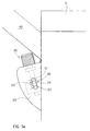
- Fig. 3a shows the opposite face of the device to the one shown in Fig. 3.
- an indicator means designated as a whole by 50, which comprises, in register with threaded stem 32, a slot 51 within which a pin 52 extends fixed to the stem 32.
- a graduated scale 53 enables to read the position of the pin 52 in the slot 51 and hence the adjustment that is being made to the position of the head 19 of the stem of the spring.
- Fig. 4 shows a variant 10a of the embodiment of Fig. 3.
- threaded stem 32 a of adjustment means 30a is fixed to a bevel pinion 55, which engages a further bevel pinion 56 whose axis is perpendicular to the axis of the stem 32.
- the pinion 56 is accessible from outside.
- adjusting means 30b comprises a ring-gear head 60, which can be operated with an engagement means (not shown) introduced through a hole 62 in the casing.
- a variant 10c of the device shown in Fig. 6, is particularly suited for hinged doors.
- a hinge between door A and structure S is referenced 13c.
- the casing 20c is fixed directly to door A and is rigid with the latter.
- the first connecting-rod element 12c is made up of a combination of casing 20c and door A.
- hinge 13c is equivalent to the fulcrum indicated by 13 for the above described devices.
- Adjusting stem 32c acts on pawl 24c and has manoeuvring knob 34c set at the bottom instead of in the top position.
- casing 20d is rigid (in a way similar to the embodiment of Fig. 6) with respect to a door A, and the latter is hinged to structure S on fulcrum 13d.
- the regulating means 30d is screwed directly in the casing and has a neck 31d for engaging a head 19d of gas spring 14d.
- the head 19d in this case has a through hole. In this way, adjusting can be performed directly on the head of the gas spring.
Landscapes
- Closing And Opening Devices For Wings, And Checks For Wings (AREA)
- Hinges (AREA)
Abstract
Description
- Fig. 1 is a broken-away perspective view of a piece of furniture provided with openable doors on an articulated-parallelogram support, with a door movement device according to the state of the art;
- Fig. 2 shows a device according to the invention, in a side view similar to that of Fig. 1, with a cover or guard removed, in an open door condition;
- Fig. 3 shows an enlarged part of Fig. 1;
- Fig. 3a shows a face opposite to that of Fig. 3;
- Fig. 4 shows a modified embodiment of the device, in which an adjusting stem is operated by means of a bevel gear pair accessible from outside;
- Fig. 5 shows a modified embodiment, represented as in Fig. 3, in which an adjusting stem is integral with a ring gear accessible from outside;
- Fig. 6 shows an embodiment for hinged doors in a similar view to that of Fig. 2;
- Fig. 7 shows an embodiment of the device for hinged doors with adjustment on a head of the gas spring.
Claims (7)
- A movement device for pieces of furniture, for articulating a door with respect to a stationary structure, comprising a first articulation element (12; 12a ...) linked to the door and pivotable with respect to the stationary structure, a second articulation element (14) hinged to the staationary structure, the ends of said two articulation elements being hinged together, the first articulation element having an elastically variable extension, so that said two elements may assume, with respect to one another, a stable retracted position and a stable extended position passing through a succession of unstable positions,
characterized in that it comprises adjustment means (30; 30a; 30b ...) for adjusting a distance between an axis (a16) of a hinge between the two elements and a rotation or pivotal axis (a13) of the second element with respect to the stationary structure. - A device according to Claim 1, characterized in that said adjusting means vary a position of the hinge (16) axis along a line belonging to a chord of a circumference having as its axis the axis (a15) of the fulcrum of the second articulation element.
- A device according to Claim 1, characterized in that said first articulation element (12) comprises a casing (20) with an internal housing (22); a pawl (24) movable for a length within said housing (22), and having said hinge (16) for the other element; and in addition, an adjusting means (30) engaging said pawl for displacing the same.
- A device according to Claim 3, characterized in that the adjusting means (30) comprises a threaded stem (32) and a manoeuvring means (34), whilst said pawl has a threaded hole.
- A device according to Claim 4, characterized in that the manoeuvring means is one of the following: a manoeuvring knob, a bevel gear pair, a ring-gear manoeuvring head.
- A device according to Claim 1, characterized in that said first element comprises a casing fixed to said door, and said door is hinged to the stationary structure, said casing comprising a housing, and said adjusting means comprising a pawl in said housing provided with a threaded hole, and an adjusting means for adjusting the position of the pawl in the housing.
- A device according to Claim 1, characterized in that said first element (12d) comprises a casing, a threaded hole in the casing, an adjusting means (30d) with a threaded stem engaged in said threaded hole, said adjusting means being engaged with a head (19d) of the second element (14d).
Priority Applications (4)
| Application Number | Priority Date | Filing Date | Title |
|---|---|---|---|
| ES00830344T ES2320086T3 (en) | 2000-05-12 | 2000-05-12 | SPRING-DRIVED DEVICE FOR MOVEMENT OF A DOOR, WITH AN ADJUSTABLE SPRING ARM ARM. |
| EP00830344A EP1154109B1 (en) | 2000-05-12 | 2000-05-12 | A spring operated device for door movement, having an adjustable lever arm of the spring |
| DE60041326T DE60041326D1 (en) | 2000-05-12 | 2000-05-12 | Spring drive device for doors, with adjustable lever arm of the spring |
| US09/842,170 US20010039762A1 (en) | 2000-05-12 | 2001-04-26 | Spring operated device for door movement, having an adjustable lever arm of the spring |
Applications Claiming Priority (1)
| Application Number | Priority Date | Filing Date | Title |
|---|---|---|---|
| EP00830344A EP1154109B1 (en) | 2000-05-12 | 2000-05-12 | A spring operated device for door movement, having an adjustable lever arm of the spring |
Publications (2)
| Publication Number | Publication Date |
|---|---|
| EP1154109A1 true EP1154109A1 (en) | 2001-11-14 |
| EP1154109B1 EP1154109B1 (en) | 2009-01-07 |
Family
ID=8175325
Family Applications (1)
| Application Number | Title | Priority Date | Filing Date |
|---|---|---|---|
| EP00830344A Expired - Lifetime EP1154109B1 (en) | 2000-05-12 | 2000-05-12 | A spring operated device for door movement, having an adjustable lever arm of the spring |
Country Status (4)
| Country | Link |
|---|---|
| US (1) | US20010039762A1 (en) |
| EP (1) | EP1154109B1 (en) |
| DE (1) | DE60041326D1 (en) |
| ES (1) | ES2320086T3 (en) |
Cited By (16)
| Publication number | Priority date | Publication date | Assignee | Title |
|---|---|---|---|---|
| DE102004019785A1 (en) * | 2004-04-23 | 2005-11-17 | Hetal-Werke Franz Hettich Gmbh & Co. Kg | Flap fitting e.g. for furniture flap, positioned between safe in cabinet body locking vertical closing position and open position upward adjustable with setting lever and in operation position axle |
| WO2006005086A1 (en) * | 2004-07-14 | 2006-01-19 | Julius Blum Gmbh | Actuating mechanism for a swivel-mounted actuating arm |
| DE10203269B4 (en) * | 2002-01-29 | 2006-07-06 | Hetal-Werke Franz Hettich Gmbh & Co | Fitting device for a furniture flap |
| WO2006111236A1 (en) * | 2005-04-20 | 2006-10-26 | Huwil-Werke Gmbh Möbelschloss- Und Beschlagfabriken | Retaining element |
| EP1785567A2 (en) * | 2005-11-10 | 2007-05-16 | Hetal-Werke Franz Hettich GmbH & Co. KG | Fitting for a cabinet lid |
| EP2309086A1 (en) * | 2009-10-07 | 2011-04-13 | Heinrich J. Kesseböhmer KG | Holding element for adjusting a cover of a piece of furniture |
| AT509206A4 (en) * | 2010-02-16 | 2011-07-15 | Gatterbauer Rupert Josef | DEVICE FOR DISPLACING A CLOSURE WALL FOR AN OPENING, IN PARTICULAR A TOP OPENING OF A FURNITURE BASKET |
| AT510984A4 (en) * | 2011-02-22 | 2012-08-15 | Blum Gmbh Julius | ACTUATOR FOR MOVING A FURNITURE FLAP |
| WO2014134642A1 (en) * | 2013-03-04 | 2014-09-12 | Julius Blum Gmbh | Actuator for a furniture flap |
| AT515493A1 (en) * | 2014-03-13 | 2015-09-15 | Blum Gmbh Julius | Actuator for furniture flaps |
| WO2016097388A1 (en) * | 2014-12-19 | 2016-06-23 | Centre National De La Recherche Scientifique (C.N.R.S) | Load-balancing device for articulated arm, associated load-handling apparatus and method |
| JP2017536492A (en) * | 2014-11-21 | 2017-12-07 | ユリウス・ブルム・ゲゼルシャフト・ミット・ベシュレンクテル・ハフツングJulius Blum Gesellschaft Mit Beschrankter Haftung | Drive unit for movable furniture parts |
| IT201700062317A1 (en) * | 2017-06-07 | 2018-12-07 | Effegi Brevetti Srl | HINGE FOR FURNITURE WITH CLOSING FORCE ADJUSTMENT DEVICE |
| AT16381U1 (en) * | 2016-02-26 | 2019-08-15 | Blum Gmbh Julius | Deputy arm drive |
| US11060337B2 (en) * | 2017-04-18 | 2021-07-13 | Hettich-Oni Gmbh & Co. Kg | Pivot drive and piece of furniture |
| CN113482477A (en) * | 2021-07-12 | 2021-10-08 | 合肥长安汽车有限公司 | Multi-connecting-rod type automobile engine front cover hinge |
Families Citing this family (54)
| Publication number | Priority date | Publication date | Assignee | Title |
|---|---|---|---|---|
| US6578234B2 (en) * | 2001-09-25 | 2003-06-17 | Midway Products Group, Inc. | Four bar hinge for vehicle rear deck lid |
| DE10223026C5 (en) * | 2002-05-22 | 2007-11-08 | Huwil-Werke Gmbh Möbelschloss- Und Beschlagfabriken | cover plate |
| ITMI20050150U1 (en) * | 2005-04-27 | 2006-10-28 | Geco System Spa | SLEEVE FOR THE PROTECTION AND IRROBUSTMENT OF WELDING HEAD-HEAD OF PLASTIC TUBES |
| US8162412B2 (en) * | 2005-09-20 | 2012-04-24 | Sca Hygiene Products Ab | Dispenser |
| ITMI20062235A1 (en) * | 2006-11-22 | 2008-05-23 | Agostino Ferrari Spa | ARTICULATED QUADRILATERO HINGE ASSEMBLY WITH ADAPTABLE STABILIZER BAR FOR VERTICAL MOVEMENT DOORS |
| ITMI20062232A1 (en) * | 2006-11-22 | 2008-05-23 | Agostino Ferrari Spa | HINGE WITH REDUCED DIMENSIONS FOR VERTICAL MOVEMENTS |
| DE202007005957U1 (en) * | 2007-02-19 | 2008-06-26 | Liebherr-Hausgeräte Ochsenhausen GmbH | Fridge and / or freezer |
| JP4732417B2 (en) * | 2007-10-03 | 2011-07-27 | スガツネ工業株式会社 | Movable holder |
| AT506196B1 (en) * | 2007-12-19 | 2010-10-15 | Blum Gmbh Julius | ADJUSTMENT MECHANISM FOR MOVING A HIGH-MOVABLE FLAP OF A FURNITURE |
| DE102008005463A1 (en) * | 2008-01-21 | 2009-07-23 | Huwil-Werke Gmbh Möbelschloss- Und Beschlagfabriken | Retaining element for adjusting a lid of a piece of furniture |
| EP2399270B1 (en) * | 2009-02-22 | 2013-06-12 | Mapper Lithography IP B.V. | Charged particle lithography apparatus |
| AT508529A1 (en) * | 2009-07-28 | 2011-02-15 | Blum Gmbh Julius | ACTUATOR FOR A MOVABLE FURNITURE PART |
| AT508698B1 (en) * | 2009-08-20 | 2017-07-15 | Blum Gmbh Julius | FURNITURE WITH PLATE ARRANGEMENT |
| EP2394879B1 (en) * | 2010-06-08 | 2016-12-14 | Voith Patent GmbH | Device for moving a bow ramp and bow ramp module |
| KR101199509B1 (en) | 2010-07-06 | 2012-11-12 | 금강창호기공 주식회사 | Opening and shutting structure of system windows and doors |
| DE102011002117A1 (en) * | 2011-04-15 | 2012-10-18 | Horst Lautenschläger | hinge |
| JP5415490B2 (en) * | 2011-07-29 | 2014-02-12 | スガツネ工業株式会社 | Door opening / closing device with support member and support member for door opening / closing device |
| JP5415491B2 (en) * | 2011-07-29 | 2014-02-12 | スガツネ工業株式会社 | Door opening / closing device unit and method of mounting the door opening / closing device unit |
| ITGO20110006A1 (en) * | 2011-10-20 | 2013-04-21 | N E M Nord Est Meccanica S N C | ANGULAR RETURN OPENING SYSTEM FOR BENCHES AND SHOWCASES |
| EP2809861B1 (en) * | 2012-01-30 | 2019-02-06 | Julius Blum GmbH | Actuator for a flap on an item of furniture |
| US8925346B2 (en) * | 2012-02-07 | 2015-01-06 | Thermo Fisher Scientific (Asheville) Llc | High performance freezer having cylindrical cabinet |
| US8572808B2 (en) * | 2012-02-23 | 2013-11-05 | Sub-Zero, Inc. | Controlled closure system for a hinge |
| JP5981653B2 (en) * | 2012-08-06 | 2016-08-31 | カウンシル オブ サイエンティフィック アンド インダストリアル リサーチ | Bioreactor vessel for large-scale growth of plants under aseptic conditions |
| JP5778793B2 (en) * | 2012-09-25 | 2015-09-16 | スガツネ工業株式会社 | Door opening and closing device |
| CN102913084B (en) * | 2012-10-26 | 2015-07-08 | 何厚荣 | Embedded refrigerator door hinge |
| CN105020873B (en) * | 2014-04-24 | 2018-08-07 | 珠海格力电器股份有限公司 | Motion, facing and household electrical appliance |
| AT515216B1 (en) * | 2014-05-02 | 2015-07-15 | Blum Gmbh Julius | Actuator for furniture flaps |
| US9452703B2 (en) * | 2014-05-30 | 2016-09-27 | Domino's Ip Holder Llc | Vehicle with upwardly movable door |
| US9181737B1 (en) * | 2014-06-03 | 2015-11-10 | Whirlpool Corporation | Oven door opening magnetic hinge |
| DE102015102393A1 (en) * | 2015-02-19 | 2016-08-25 | Hettich Holding Gmbh & Co. Ohg | swivel fitting |
| PL3289158T3 (en) * | 2015-04-30 | 2021-12-20 | Arturo Salice S.P.A. | Hinge for furniture leaves that swing about at least one horizontal axis |
| EP3409959B1 (en) * | 2016-01-28 | 2020-07-15 | Shanghai Hingwah Honeycomb Technology Development | Foldable deployment mechanism |
| US10181236B2 (en) * | 2016-08-18 | 2019-01-15 | Bally Gaming, Inc. | Externally hinged cabinet door for a gaming machine housing |
| JP6453280B2 (en) * | 2016-08-30 | 2019-01-16 | 有限会社新井鉄工 | Door body opening / closing device |
| IT201600098088A1 (en) * | 2016-09-30 | 2018-03-30 | Salice Arturo Spa | Control device for a lifting system and lifting system for furniture doors. |
| WO2018192819A1 (en) * | 2017-04-18 | 2018-10-25 | Hettich-Oni Gmbh & Co. Kg | Furniture board having a flap fitting and carcass and furniture item having such a furniture board |
| US10407961B2 (en) * | 2017-04-21 | 2019-09-10 | Art Design Works LLC | Door closure assembly |
| DE102017114772A1 (en) * | 2017-07-03 | 2019-01-03 | Hettich-Oni Gmbh & Co. Kg | Flap fitting and furniture |
| US10521998B2 (en) * | 2017-09-29 | 2019-12-31 | Aristocrat Technologies Australia Pty Limited | Zero weight articulating access door |
| IT201700112315A1 (en) * | 2017-10-06 | 2019-04-06 | Effegi Brevetti Srl | AUTOMATIC OPENING MECHANISM FOR HINGED DOORS |
| EP3774539B1 (en) * | 2018-04-04 | 2023-09-27 | Safran Cabin Inc. | Fixed bin hinge system |
| TR201818261A2 (en) * | 2018-11-30 | 2020-06-22 | Samet Kalip Ve Madeni Esya Sanayi Ve Ticaret Anonim Sirketi | A Furniture Hinge With Damping Adjustment |
| TR201818259A2 (en) * | 2018-11-30 | 2020-06-22 | Samet Kalip Ve Madeni Esya Sanayi Ve Ticaret Anonim Sirketi | A Furniture Hinge for Upward-Opening Cabinet Doors |
| IT201900005758A1 (en) * | 2019-04-15 | 2020-10-15 | Effegi Brevetti Srl | HINGE FOR OPENING AND CLOSING HINGED DOORS OF FURNITURE |
| EP3738466B1 (en) * | 2019-05-16 | 2021-12-22 | Vauth-Sagel Holding GmbH & Co. KG | Pivoting bracket for mounting a swinging component and cabinet with such a pivoting bracket |
| DE102019113335A1 (en) * | 2019-05-20 | 2020-11-26 | Samet Kalip Ve Maden Esya San. Ve Tic. A.S. | Furniture fittings |
| DE102019113337B4 (en) * | 2019-05-20 | 2022-07-14 | Samet Kalip Ve Maden Esya San. Ve Tic. A.S. | furniture fitting |
| US11549295B2 (en) * | 2019-08-28 | 2023-01-10 | Gulfstream Aerospace Corporation | Cabinet and method for making the same, and aircraft including a cabinet |
| US11028625B2 (en) * | 2019-09-27 | 2021-06-08 | Aristocrat Technologies Australia Pty Limited | Articulating hinge assembly for use with a gaming machine cabinet |
| CN110631156A (en) * | 2019-11-11 | 2019-12-31 | 杰马科技(中山)有限公司 | Temperature regulating fan capable of being folded and packaged and folding method thereof |
| JP7349328B2 (en) | 2019-11-12 | 2023-09-22 | スガツネ工業株式会社 | door opening/closing device |
| US11512512B2 (en) * | 2020-04-28 | 2022-11-29 | The Boeing Company | Door translation hinge assembly |
| US11846387B2 (en) * | 2021-03-04 | 2023-12-19 | Van Murphy Bed LLC | Bracket with rotatable and cantilevered support member |
| US11542739B1 (en) * | 2021-10-13 | 2023-01-03 | Shern Dar Indusrial Corp. | Door closer mechanism |
Citations (2)
| Publication number | Priority date | Publication date | Assignee | Title |
|---|---|---|---|---|
| DE2648085A1 (en) * | 1976-10-23 | 1978-04-27 | Hettich Hetal Werke | Hinge for overhead cabinet flap - has spring adjusted by changing pivot point for different flap weights |
| DE8812578U1 (en) * | 1988-10-06 | 1988-11-24 | Gerd Und Bernd Vieler Kg, 5860 Iserlohn, De |
-
2000
- 2000-05-12 EP EP00830344A patent/EP1154109B1/en not_active Expired - Lifetime
- 2000-05-12 DE DE60041326T patent/DE60041326D1/en not_active Expired - Lifetime
- 2000-05-12 ES ES00830344T patent/ES2320086T3/en not_active Expired - Lifetime
-
2001
- 2001-04-26 US US09/842,170 patent/US20010039762A1/en not_active Abandoned
Patent Citations (2)
| Publication number | Priority date | Publication date | Assignee | Title |
|---|---|---|---|---|
| DE2648085A1 (en) * | 1976-10-23 | 1978-04-27 | Hettich Hetal Werke | Hinge for overhead cabinet flap - has spring adjusted by changing pivot point for different flap weights |
| DE8812578U1 (en) * | 1988-10-06 | 1988-11-24 | Gerd Und Bernd Vieler Kg, 5860 Iserlohn, De |
Cited By (40)
| Publication number | Priority date | Publication date | Assignee | Title |
|---|---|---|---|---|
| DE10203269B4 (en) * | 2002-01-29 | 2006-07-06 | Hetal-Werke Franz Hettich Gmbh & Co | Fitting device for a furniture flap |
| DE102004019785B4 (en) * | 2004-04-23 | 2006-04-27 | Hetal-Werke Franz Hettich Gmbh & Co. Kg | Flap fitting e.g. for furniture flap, positioned between safe in cabinet body locking vertical closing position and open position upward adjustable with setting lever and in operation position axle |
| DE102004019785A1 (en) * | 2004-04-23 | 2005-11-17 | Hetal-Werke Franz Hettich Gmbh & Co. Kg | Flap fitting e.g. for furniture flap, positioned between safe in cabinet body locking vertical closing position and open position upward adjustable with setting lever and in operation position axle |
| WO2006005086A1 (en) * | 2004-07-14 | 2006-01-19 | Julius Blum Gmbh | Actuating mechanism for a swivel-mounted actuating arm |
| US7500287B2 (en) | 2004-07-14 | 2009-03-10 | Julius Blum Gmbh | Actuating mechanism for a pivotably mounted actuating arm |
| JP2009062809A (en) * | 2004-07-14 | 2009-03-26 | Julius Blum Gmbh | Drive mechanism for turnably-mounted drive arm |
| US7810213B2 (en) | 2004-07-14 | 2010-10-12 | Julius Glum Gmbh | Actuating mechanism for a pivotably mounted actuating arm |
| JP4787252B2 (en) * | 2004-07-14 | 2011-10-05 | ユリウス ブルム ゲー エム ベー ハー | Drive mechanism for drive arm mounted so as to be pivotable |
| CN1985064B (en) * | 2004-07-14 | 2011-08-24 | 尤利乌斯·布卢姆有限公司 | Actuating mechanism for a pivotably mounted actuating arm |
| US7976079B2 (en) | 2005-04-20 | 2011-07-12 | Toplifter Beteiligungs-und Vertriebs GmbH & Co. KG | Retaining element |
| WO2006111236A1 (en) * | 2005-04-20 | 2006-10-26 | Huwil-Werke Gmbh Möbelschloss- Und Beschlagfabriken | Retaining element |
| EP1785567A2 (en) * | 2005-11-10 | 2007-05-16 | Hetal-Werke Franz Hettich GmbH & Co. KG | Fitting for a cabinet lid |
| EP1785567A3 (en) * | 2005-11-10 | 2010-10-20 | Hetal-Werke Franz Hettich GmbH & Co. KG | Fitting for a cabinet lid |
| EP2309086A1 (en) * | 2009-10-07 | 2011-04-13 | Heinrich J. Kesseböhmer KG | Holding element for adjusting a cover of a piece of furniture |
| AT509206A4 (en) * | 2010-02-16 | 2011-07-15 | Gatterbauer Rupert Josef | DEVICE FOR DISPLACING A CLOSURE WALL FOR AN OPENING, IN PARTICULAR A TOP OPENING OF A FURNITURE BASKET |
| AT509206B1 (en) * | 2010-02-16 | 2011-07-15 | Gatterbauer Rupert Josef | DEVICE FOR DISPLACING A CLOSURE WALL FOR AN OPENING, IN PARTICULAR A TOP OPENING OF A FURNITURE BASKET |
| AT510984A4 (en) * | 2011-02-22 | 2012-08-15 | Blum Gmbh Julius | ACTUATOR FOR MOVING A FURNITURE FLAP |
| AT510984B1 (en) * | 2011-02-22 | 2012-08-15 | Blum Gmbh Julius | ACTUATOR FOR MOVING A FURNITURE FLAP |
| WO2014134642A1 (en) * | 2013-03-04 | 2014-09-12 | Julius Blum Gmbh | Actuator for a furniture flap |
| AT514050A1 (en) * | 2013-03-04 | 2014-09-15 | Blum Gmbh Julius | Actuator for a furniture flap |
| RU2603567C1 (en) * | 2013-03-04 | 2016-11-27 | Юлиус Блум Гмбх | Actuator for flap door of furniture |
| AT16472U1 (en) * | 2013-03-04 | 2019-10-15 | Blum Gmbh Julius | Actuator for a furniture flap |
| US9506283B2 (en) | 2013-03-04 | 2016-11-29 | Julius Blum Gmbh | Actuator for a furniture flap |
| AT515493A1 (en) * | 2014-03-13 | 2015-09-15 | Blum Gmbh Julius | Actuator for furniture flaps |
| DE202015009804U1 (en) | 2014-03-13 | 2020-03-19 | Julius Blum Gmbh | Actuator for furniture flaps |
| US9719283B2 (en) | 2014-03-13 | 2017-08-01 | Julius Blum Gmbh | Actuating drive for furniture flaps |
| EP3754143A1 (en) | 2014-03-13 | 2020-12-23 | Julius Blum GmbH | Actuator for furniture |
| AT16873U1 (en) * | 2014-03-13 | 2020-11-15 | Blum Gmbh Julius | Actuator for furniture flaps |
| US10487554B2 (en) | 2014-11-21 | 2019-11-26 | Julius Blum Gmbh | Actuator for movable furniture parts |
| JP2017536492A (en) * | 2014-11-21 | 2017-12-07 | ユリウス・ブルム・ゲゼルシャフト・ミット・ベシュレンクテル・ハフツングJulius Blum Gesellschaft Mit Beschrankter Haftung | Drive unit for movable furniture parts |
| US10293495B2 (en) | 2014-12-19 | 2019-05-21 | Centre National De La Recherche Scientifique | Load-balancing device for articulated arm, associated load-handling apparatus and method |
| WO2016097388A1 (en) * | 2014-12-19 | 2016-06-23 | Centre National De La Recherche Scientifique (C.N.R.S) | Load-balancing device for articulated arm, associated load-handling apparatus and method |
| FR3030337A1 (en) * | 2014-12-19 | 2016-06-24 | Centre Nat De La Rech Scient (C N R S) | LOAD BALANCING DEVICE FOR ARTICULATED ARM, ASSOCIATED LOAD HANDLING APPARATUS AND METHOD |
| AT16381U1 (en) * | 2016-02-26 | 2019-08-15 | Blum Gmbh Julius | Deputy arm drive |
| US10662690B2 (en) | 2016-02-26 | 2020-05-26 | Julius Blum Gmbh | Actuating arm drive |
| US11060337B2 (en) * | 2017-04-18 | 2021-07-13 | Hettich-Oni Gmbh & Co. Kg | Pivot drive and piece of furniture |
| WO2018224505A1 (en) | 2017-06-07 | 2018-12-13 | Effegi Brevetti S.R.L. | Hinge for furniture with device for regulating the closing force |
| IT201700062317A1 (en) * | 2017-06-07 | 2018-12-07 | Effegi Brevetti Srl | HINGE FOR FURNITURE WITH CLOSING FORCE ADJUSTMENT DEVICE |
| US11105137B2 (en) | 2017-06-07 | 2021-08-31 | Effegi Brevetti S.R.L. | Hinge for furniture with device for regulating the closing force |
| CN113482477A (en) * | 2021-07-12 | 2021-10-08 | 合肥长安汽车有限公司 | Multi-connecting-rod type automobile engine front cover hinge |
Also Published As
| Publication number | Publication date |
|---|---|
| EP1154109B1 (en) | 2009-01-07 |
| US20010039762A1 (en) | 2001-11-15 |
| DE60041326D1 (en) | 2009-02-26 |
| ES2320086T3 (en) | 2009-05-19 |
Similar Documents
| Publication | Publication Date | Title |
|---|---|---|
| EP1154109B1 (en) | A spring operated device for door movement, having an adjustable lever arm of the spring | |
| US4163344A (en) | Oven hinge mechanism including cam balance modifier | |
| US5373665A (en) | Door assembly with augmented counterbalancing | |
| AU2006202911B2 (en) | Snap hinge for supporting a closure element | |
| JP4714264B2 (en) | Holding member | |
| US6460816B1 (en) | Adjustable computer keyboard platform support mechanism | |
| US6041548A (en) | Support arm | |
| RU2429333C2 (en) | Furniture hinge | |
| US5493759A (en) | Articulated furniture hinge having a pivotally adjustable hinge arm producing lateral or vertical member translation | |
| GB2042059A (en) | Furniture hinge | |
| US4152811A (en) | Over-center hinge | |
| US3414933A (en) | Hinge with spring for counter-balance of flaps | |
| EP1508663A1 (en) | An improved pivot window with at least one auxiliary opening device | |
| CA2462936A1 (en) | Hinge | |
| CA2228066A1 (en) | Mower deck lid locking mechanism | |
| US5435103A (en) | Compact window operator | |
| BR0302743A (en) | Planting Unit Locking Assembly | |
| US4365384A (en) | Concealed multi pintle latch hinge | |
| US4388745A (en) | Self closing multi pintle hinge | |
| US20100071266A1 (en) | Window operating mechanism | |
| JP3454573B2 (en) | Counter window operator | |
| GB2226361A (en) | Telescopic spring | |
| AU2002360230A1 (en) | Casement window operator system | |
| JP3613081B2 (en) | Lifting storage device | |
| WO2003042479A1 (en) | Casement window operator system |
Legal Events
| Date | Code | Title | Description |
|---|---|---|---|
| PUAI | Public reference made under article 153(3) epc to a published international application that has entered the european phase |
Free format text: ORIGINAL CODE: 0009012 |
|
| AK | Designated contracting states |
Kind code of ref document: A1 Designated state(s): DE ES FR IT Kind code of ref document: A1 Designated state(s): AT BE CH CY DE DK ES FI FR GB GR IE IT LI LU MC NL PT SE |
|
| AX | Request for extension of the european patent |
Free format text: AL;LT;LV;MK;RO;SI |
|
| 17P | Request for examination filed |
Effective date: 20020417 |
|
| AKX | Designation fees paid |
Free format text: DE ES FR IT |
|
| 17Q | First examination report despatched |
Effective date: 20071228 |
|
| GRAP | Despatch of communication of intention to grant a patent |
Free format text: ORIGINAL CODE: EPIDOSNIGR1 |
|
| GRAS | Grant fee paid |
Free format text: ORIGINAL CODE: EPIDOSNIGR3 |
|
| GRAA | (expected) grant |
Free format text: ORIGINAL CODE: 0009210 |
|
| AK | Designated contracting states |
Kind code of ref document: B1 Designated state(s): DE ES FR IT |
|
| REF | Corresponds to: |
Ref document number: 60041326 Country of ref document: DE Date of ref document: 20090226 Kind code of ref document: P |
|
| REG | Reference to a national code |
Ref country code: ES Ref legal event code: FG2A Ref document number: 2320086 Country of ref document: ES Kind code of ref document: T3 |
|
| PLBE | No opposition filed within time limit |
Free format text: ORIGINAL CODE: 0009261 |
|
| STAA | Information on the status of an ep patent application or granted ep patent |
Free format text: STATUS: NO OPPOSITION FILED WITHIN TIME LIMIT |
|
| 26N | No opposition filed |
Effective date: 20091008 |
|
| PGFP | Annual fee paid to national office [announced via postgrant information from national office to epo] |
Ref country code: ES Payment date: 20120511 Year of fee payment: 13 |
|
| PGFP | Annual fee paid to national office [announced via postgrant information from national office to epo] |
Ref country code: DE Payment date: 20130529 Year of fee payment: 14 |
|
| PGFP | Annual fee paid to national office [announced via postgrant information from national office to epo] |
Ref country code: IT Payment date: 20130513 Year of fee payment: 14 Ref country code: FR Payment date: 20130607 Year of fee payment: 14 |
|
| REG | Reference to a national code |
Ref country code: DE Ref legal event code: R119 Ref document number: 60041326 Country of ref document: DE |
|
| REG | Reference to a national code |
Ref country code: DE Ref legal event code: R119 Ref document number: 60041326 Country of ref document: DE Effective date: 20141202 |
|
| REG | Reference to a national code |
Ref country code: FR Ref legal event code: ST Effective date: 20150130 |
|
| PG25 | Lapsed in a contracting state [announced via postgrant information from national office to epo] |
Ref country code: IT Free format text: LAPSE BECAUSE OF NON-PAYMENT OF DUE FEES Effective date: 20140512 Ref country code: DE Free format text: LAPSE BECAUSE OF NON-PAYMENT OF DUE FEES Effective date: 20141202 |
|
| PG25 | Lapsed in a contracting state [announced via postgrant information from national office to epo] |
Ref country code: FR Free format text: LAPSE BECAUSE OF NON-PAYMENT OF DUE FEES Effective date: 20140602 |
|
| REG | Reference to a national code |
Ref country code: ES Ref legal event code: FD2A Effective date: 20150630 |
|
| PG25 | Lapsed in a contracting state [announced via postgrant information from national office to epo] |
Ref country code: ES Free format text: LAPSE BECAUSE OF NON-PAYMENT OF DUE FEES Effective date: 20140513 |