EP1154108A2 - Tube for connection to the actuation handle and to the corresponding end of a swivel bolt for closing wings of doors of trucks, trailers or the like - Google Patents
Tube for connection to the actuation handle and to the corresponding end of a swivel bolt for closing wings of doors of trucks, trailers or the like Download PDFInfo
- Publication number
- EP1154108A2 EP1154108A2 EP01109465A EP01109465A EP1154108A2 EP 1154108 A2 EP1154108 A2 EP 1154108A2 EP 01109465 A EP01109465 A EP 01109465A EP 01109465 A EP01109465 A EP 01109465A EP 1154108 A2 EP1154108 A2 EP 1154108A2
- Authority
- EP
- European Patent Office
- Prior art keywords
- tube
- swivel bolt
- trailers
- trucks
- doors
- Prior art date
- Legal status (The legal status is an assumption and is not a legal conclusion. Google has not performed a legal analysis and makes no representation as to the accuracy of the status listed.)
- Withdrawn
Links
Images


Classifications
-
- E—FIXED CONSTRUCTIONS
- E05—LOCKS; KEYS; WINDOW OR DOOR FITTINGS; SAFES
- E05B—LOCKS; ACCESSORIES THEREFOR; HANDCUFFS
- E05B83/00—Vehicle locks specially adapted for particular types of wing or vehicle
- E05B83/02—Locks for railway freight-cars, freight containers or the like; Locks for the cargo compartments of commercial lorries, trucks or vans
- E05B83/08—Locks for railway freight-cars, freight containers or the like; Locks for the cargo compartments of commercial lorries, trucks or vans with elongated bars for actuating the fastening means
- E05B83/10—Rotary bars
Definitions
- the present invention relates to a tube for connection to the actuation handle and to the corresponding end of a swivel bolt for closing wings of doors of trucks, trailers or the like.
- tubes having a circular cross-section for connection to the actuation handle and to corresponding ends of two swivel bolts, an upper one and a lower one, for closing wings of doors of trucks, trailers or the like: such tubes have some drawbacks in relation to their coupling to the swivel bolts and swiveling actuation handle, which usually occurs by welding to the two bolts and by means of diametrical pins or welding as regards coupling the manual grip handle to the tube; this entails a considerable waste of time and the need to use welding units or the like in order to assemble the components.
- the aim of the present invention is to obviate the above-cited drawbacks and meet the mentioned needs, i.e., to provide a tube for connection to the actuation handle and to the corresponding end of a swivel bolt end for closing wings of doors of trucks, trailers or the like which can be assembled easily and rapidly without requiring particular accuracy or welding or the like.
- an object of the present invention is to provide a tube which is simple, relatively easy to provide in practice, safe in use, effective in operation, and has a relatively low cost.
- the present tube for connection to the actuation handle and to the corresponding end of a swivel bolt for closing wings of doors of trucks, trailers or the like, characterized in that the tube and the end of the swivel bolt have complementary cross-sections shaped like polygons having convex sides.
- the reference numeral 1 generally designates a tube for connection to the actuation handle M and to the corresponding end 2 of a swivel bolt 3 for closing wings of doors of trucks, trailers or the like according to the invention.
- the tube 1 and the end 2 of the swivel bolt have complementary cross-sections which are shaped like a regular polygon, particularly like a triangle having three slightly convex sides 4; the end 2 substantially forms a coupling tang with preferably curved surfaces and a slightly rounded tip 2a.
- Figures 1 and 4 illustrate two alternative and preferred embodiments of the rotary coupling of the bolt 3 to a corresponding support 5.
- the support 5 is advantageously formed by two portions 6 and 7 (as illustrated in Figure 3) made of stamped metal plate (or aluminum section), respectively a lower portion and an upper portion, which are crossed by corresponding holes 8 for fixing to the wing.
- a cylindrical seat 9 for the rotation of the stem 10 of the bolt is formed between the portions 6 and 7 in a central position.
- an intermediate region 10a of the stem 10 comprised between two annular raised portions 11 and 12 of the stem (known in the field as "anti-rack ridges") is placed between the portions 6 and 7: in this embodiment, two bushes 13 and 14 are fitted between the inlets of the seat 9 and the region 10a of the stem, and each bush is constituted by two bush portions advantageously made of a material such as bronze coated with PTFE.
- the stem 10 has a single raised portion 15 and in the portions 6 and 7 there are two complementary recesses 16 and 17 for centering the raised portion 15 and two complementary recesses 18 and 19 for centering a bush 20 which is advantageously made of synthetic materials of the type known by the tradename Nylon.
- the bush 20 has an internal hole, whose cross-section is shaped like an equilateral triangle with slightly convex sides so as to mate with the outer surface of the tube 1, and is externally cylindrical so as to be arranged rotatably in the recesses 18 and 19.
- a similar bush 21 provides the coupling to the box S of the handle M; the handle is crossed by a hole F which is substantially identical to the external cross-section of the tube and requires no welding or pins.
- the tube 1 can have a different cross-section than the one shown and its external cross-section need not be the same as its internal one (for example, it might be triangular externally and square internally).
- the operation of the invention is self-evident: in order to couple the tube 1 to the end 2 it is sufficient to fit it, after cutting it to size, on the tip of the end 2 and fit the upper portion 7 of the support 5; any small differences in the length of the tube 1 are compensated by possible small relative movements of the tube 1 and the end 2.
- the tube 1 serves only to transmit the rotation to the pawls and has no other functions for vertical support of said pawls: assembly is simplified, since the fitter (differently from what occurs instead with conventional rods) is practically forced to leave no play between the anti-rack washers and the supports 5.
- the invention achieves the intended aim and object, and in particular that it provides a tube for connection to the actuation handle and to the corresponding end of a swivel bolt for closing wings of doors of trucks, trailers or the like which can be assembled easily and rapidly without requiring particular accuracy or welding or the like.
- the tube can have a hexagonal, square, oval or other cross-section and the outer cross-section can be different from the inner one.
Abstract
Description
- The present invention relates to a tube for connection to the actuation handle and to the corresponding end of a swivel bolt for closing wings of doors of trucks, trailers or the like.
- It is known to use tubes having a circular cross-section for connection to the actuation handle and to corresponding ends of two swivel bolts, an upper one and a lower one, for closing wings of doors of trucks, trailers or the like: such tubes have some drawbacks in relation to their coupling to the swivel bolts and swiveling actuation handle, which usually occurs by welding to the two bolts and by means of diametrical pins or welding as regards coupling the manual grip handle to the tube; this entails a considerable waste of time and the need to use welding units or the like in order to assemble the components.
- Assembling the components by welding requires some care so that the bolts turn out co-planar; moreover, the tube must be cut and welded to the bolts with an exactly measured length.
- The aim of the present invention is to obviate the above-cited drawbacks and meet the mentioned needs, i.e., to provide a tube for connection to the actuation handle and to the corresponding end of a swivel bolt end for closing wings of doors of trucks, trailers or the like which can be assembled easily and rapidly without requiring particular accuracy or welding or the like.
- Within this aim, an object of the present invention is to provide a tube which is simple, relatively easy to provide in practice, safe in use, effective in operation, and has a relatively low cost.
- This aim and this and other objects which will become better apparent hereinafter are achieved by the present tube for connection to the actuation handle and to the corresponding end of a swivel bolt for closing wings of doors of trucks, trailers or the like, characterized in that the tube and the end of the swivel bolt have complementary cross-sections shaped like polygons having convex sides.
- Further characteristics and advantages of the present invention will become better apparent from the following detailed description of a preferred but not exclusive embodiment of a tube for connection to the actuation handle and to the corresponding end of a swivel bolt for closing wings of doors of trucks, trailers or the like according to the invention, illustrated only by way of non-limitative example in the accompanying drawings, wherein:
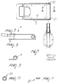
- Figure 1 is a sectional front view of a tube with the corresponding swivel bolt end and support for articulation to the wing;
- Figure 2 is a sectional view, taken along the line II-II of Figure 1;
- Figure 3 is a sectional view, taken along the line III-III of Figure 1;
- Figure 4 is a sectional front view of a tube with a corresponding swivel bolt end and support for articulation to the wing in a provided solution which is alternative to the one shown in Figure 1;
- Figure 5 is a sectional view, taken along the line V-V of Figure 4;
- Figure 6 is a sectional view, taken along the line VI-VI of Figure 4;
- Figures 7 and 8 are, respectively, a partially sectional front view and a bottom view of a handle preset for coupling to the tube according to the invention;
- Figure 9 is a sectional view of a portion of a handle, taken along the line IX-IX of Figure 7;
- Figures 10 and 11 are, respectively, a front view and a side view of a bush of the handle.
-
- With reference to the figures, the
reference numeral 1 generally designates a tube for connection to the actuation handle M and to thecorresponding end 2 of aswivel bolt 3 for closing wings of doors of trucks, trailers or the like according to the invention. - The
tube 1 and theend 2 of the swivel bolt have complementary cross-sections which are shaped like a regular polygon, particularly like a triangle having three slightlyconvex sides 4; theend 2 substantially forms a coupling tang with preferably curved surfaces and a slightly rounded tip 2a. - Figures 1 and 4 illustrate two alternative and preferred embodiments of the rotary coupling of the
bolt 3 to acorresponding support 5. - In Figure 1, the
support 5 is advantageously formed by two portions 6 and 7 (as illustrated in Figure 3) made of stamped metal plate (or aluminum section), respectively a lower portion and an upper portion, which are crossed bycorresponding holes 8 for fixing to the wing. - A
cylindrical seat 9 for the rotation of thestem 10 of the bolt is formed between theportions 6 and 7 in a central position. - In the embodiment shown in Figure 1, an
intermediate region 10a of thestem 10 comprised between two annular raisedportions 11 and 12 of the stem (known in the field as "anti-rack ridges") is placed between the portions 6 and 7: in this embodiment, twobushes seat 9 and theregion 10a of the stem, and each bush is constituted by two bush portions advantageously made of a material such as bronze coated with PTFE. - In another embodiment, illustrated in Figure 4, the
stem 10 has a single raisedportion 15 and in theportions 6 and 7 there are twocomplementary recesses portion 15 and twocomplementary recesses bush 20 which is advantageously made of synthetic materials of the type known by the tradename Nylon. - The
bush 20 has an internal hole, whose cross-section is shaped like an equilateral triangle with slightly convex sides so as to mate with the outer surface of thetube 1, and is externally cylindrical so as to be arranged rotatably in therecesses - Likewise, a
similar bush 21 provides the coupling to the box S of the handle M; the handle is crossed by a hole F which is substantially identical to the external cross-section of the tube and requires no welding or pins. - The
tube 1 can have a different cross-section than the one shown and its external cross-section need not be the same as its internal one (for example, it might be triangular externally and square internally). - The operation of the invention is self-evident: in order to couple the
tube 1 to theend 2 it is sufficient to fit it, after cutting it to size, on the tip of theend 2 and fit theupper portion 7 of thesupport 5; any small differences in the length of thetube 1 are compensated by possible small relative movements of thetube 1 and theend 2. - It is noted that the
anti-rack ridges tube 1 serves only to transmit the rotation to the pawls and has no other functions for vertical support of said pawls: assembly is simplified, since the fitter (differently from what occurs instead with conventional rods) is practically forced to leave no play between the anti-rack washers and thesupports 5. - It has thus been observed that the invention achieves the intended aim and object, and in particular that it provides a tube for connection to the actuation handle and to the corresponding end of a swivel bolt for closing wings of doors of trucks, trailers or the like which can be assembled easily and rapidly without requiring particular accuracy or welding or the like.
- The invention thus conceived is susceptible of numerous modifications and variations, all of which are within the scope of the inventive concept; thus, for example, the tube can have a hexagonal, square, oval or other cross-section and the outer cross-section can be different from the inner one.
- All the details may further be replaced with other technically equivalent ones.
- In practice, the materials used, as well as the shapes and the dimensions, may be any according to requirements without thereby abandoning the scope of the protection of the appended claims.
- The disclosures in Italian Utility Model Application No. BO2000U000068 from which this application claims priority are incorporated herein by reference.
- Where technical features mentioned in any claim are followed by reference signs, those reference signs have been included for the sole purpose of increasing the intelligibility of the claims and accordingly, such reference signs do not have any limiting effect on the interpretation of each element identified by way of example by such reference signs.
Claims (4)
- A tube for connection to the actuation handle and to the corresponding end of a swivel bolt for closing wings of doors of trucks, trailers or the like, characterized in that the tube and the end of the swivel bolt have complementary cross-sections shaped like a polygon.
- The tube according to claim 1, characterized in that said polygon is regular and has convex sides.
- The tube according to one or more of the preceding claims, characterized in that said polygon is three-sided.
- The tube according to one or more of the preceding claims, characterized in that for the rotary coupling of the bolt to a corresponding support fixed to the wing and for the box of the handle a bush is provided which is made of synthetic materials, has an internal hole whose cross-section is complementary to the cross-section of the tube, and is externally cylindrical.
Applications Claiming Priority (2)
| Application Number | Priority Date | Filing Date | Title |
|---|---|---|---|
| ITBO000068U | 2000-05-11 | ||
| IT2000BO000068 IT251108Y1 (en) | 2000-05-11 | 2000-05-11 | CONNECTION TUBE TO THE DRIVE HANDLE AND RELEVANT ROTATING LOCK TERMINAL FOR CLOSING DOORS OF CAMIO HATCHES |
Publications (2)
| Publication Number | Publication Date |
|---|---|
| EP1154108A2 true EP1154108A2 (en) | 2001-11-14 |
| EP1154108A3 EP1154108A3 (en) | 2002-06-05 |
Family
ID=11438176
Family Applications (1)
| Application Number | Title | Priority Date | Filing Date |
|---|---|---|---|
| EP01109465A Withdrawn EP1154108A3 (en) | 2000-05-11 | 2001-04-24 | Tube for connection to the actuation handle and to the corresponding end of a swivel bolt for closing wings of doors of trucks, trailers or the like |
Country Status (2)
| Country | Link |
|---|---|
| EP (1) | EP1154108A3 (en) |
| IT (1) | IT251108Y1 (en) |
Cited By (1)
| Publication number | Priority date | Publication date | Assignee | Title |
|---|---|---|---|---|
| EP1900892A1 (en) * | 2006-09-06 | 2008-03-19 | F. HESTERBERG & SÖHNE GmbH & Co. KG | Espagnolette bolt |
Citations (4)
| Publication number | Priority date | Publication date | Assignee | Title |
|---|---|---|---|---|
| DE81133C (en) * | ||||
| US1952112A (en) * | 1931-05-04 | 1934-03-27 | Universal Draft Gear Attachmen | Door fastening device |
| FR2215085A5 (en) * | 1973-01-19 | 1974-08-19 | Sautet Edmond | |
| US3912312A (en) * | 1972-10-16 | 1975-10-14 | Piero Cerutti | Locking system for container doors and the like |
-
2000
- 2000-05-11 IT IT2000BO000068 patent/IT251108Y1/en active
-
2001
- 2001-04-24 EP EP01109465A patent/EP1154108A3/en not_active Withdrawn
Patent Citations (4)
| Publication number | Priority date | Publication date | Assignee | Title |
|---|---|---|---|---|
| DE81133C (en) * | ||||
| US1952112A (en) * | 1931-05-04 | 1934-03-27 | Universal Draft Gear Attachmen | Door fastening device |
| US3912312A (en) * | 1972-10-16 | 1975-10-14 | Piero Cerutti | Locking system for container doors and the like |
| FR2215085A5 (en) * | 1973-01-19 | 1974-08-19 | Sautet Edmond |
Cited By (1)
| Publication number | Priority date | Publication date | Assignee | Title |
|---|---|---|---|---|
| EP1900892A1 (en) * | 2006-09-06 | 2008-03-19 | F. HESTERBERG & SÖHNE GmbH & Co. KG | Espagnolette bolt |
Also Published As
| Publication number | Publication date |
|---|---|
| ITBO20000068U1 (en) | 2001-11-11 |
| EP1154108A3 (en) | 2002-06-05 |
| IT251108Y1 (en) | 2003-11-04 |
Similar Documents
| Publication | Publication Date | Title |
|---|---|---|
| US5737841A (en) | Pocket knife with lock | |
| AU773224B2 (en) | A folding hancle | |
| WO2007031418A1 (en) | Door for a refrigeration device | |
| AU747733B2 (en) | Torsion holder for conveyor belt scraper | |
| BRPI0507109B1 (en) | one-way mounting hinge | |
| AU596278B2 (en) | Pivot joint | |
| EP1154108A2 (en) | Tube for connection to the actuation handle and to the corresponding end of a swivel bolt for closing wings of doors of trucks, trailers or the like | |
| DE2725682A1 (en) | ROLLERS | |
| US1679039A (en) | Tool | |
| CS198250B2 (en) | Drafting instrument | |
| US20030200624A1 (en) | Hinges | |
| KR200237084Y1 (en) | Cutting machine for cable cutting | |
| US5979877A (en) | Jack for vehicle | |
| EP0439840A1 (en) | Handle assembly | |
| JP3348062B2 (en) | Metal dust prevention hinge | |
| CZ9202005A3 (en) | Door hinge for motor vehicles | |
| CN213330854U (en) | Suspension translation door alternately strengthens pull rod assembly | |
| AU604579B2 (en) | Toilet seat assembly | |
| CN217714855U (en) | Combined desk lamp rotating shaft structure and desk lamp | |
| JPS6212673Y2 (en) | ||
| JP2958309B1 (en) | Metal dust prevention hinge | |
| AU2009240862A1 (en) | A Pivot Joint | |
| BRMU8801927Y1 (en) | sliding shelf rod joint structure | |
| KR910004413Y1 (en) | Prefabricated leg of the chair | |
| DK200000387U3 (en) | Fittings for windows and their use. |
Legal Events
| Date | Code | Title | Description |
|---|---|---|---|
| PUAI | Public reference made under article 153(3) epc to a published international application that has entered the european phase |
Free format text: ORIGINAL CODE: 0009012 |
|
| AK | Designated contracting states |
Kind code of ref document: A2 Designated state(s): AT BE CH CY DE DK ES FI FR GB GR IE IT LI LU MC NL PT SE TR |
|
| AX | Request for extension of the european patent |
Free format text: AL;LT;LV;MK;RO;SI |
|
| PUAL | Search report despatched |
Free format text: ORIGINAL CODE: 0009013 |
|
| AK | Designated contracting states |
Kind code of ref document: A3 Designated state(s): AT BE CH CY DE DK ES FI FR GB GR IE IT LI LU MC NL PT SE TR |
|
| AX | Request for extension of the european patent |
Free format text: AL;LT;LV;MK;RO;SI |
|
| 17P | Request for examination filed |
Effective date: 20021120 |
|
| AKX | Designation fees paid |
Designated state(s): AT BE CH CY DE DK ES FI FR GB GR IE IT LI LU MC NL PT SE TR |
|
| 17Q | First examination report despatched |
Effective date: 20030919 |
|
| STAA | Information on the status of an ep patent application or granted ep patent |
Free format text: STATUS: THE APPLICATION IS DEEMED TO BE WITHDRAWN |
|
| 18D | Application deemed to be withdrawn |
Effective date: 20040130 |