EP1154106A2 - Latch assembly - Google Patents
Latch assembly Download PDFInfo
- Publication number
- EP1154106A2 EP1154106A2 EP01304266A EP01304266A EP1154106A2 EP 1154106 A2 EP1154106 A2 EP 1154106A2 EP 01304266 A EP01304266 A EP 01304266A EP 01304266 A EP01304266 A EP 01304266A EP 1154106 A2 EP1154106 A2 EP 1154106A2
- Authority
- EP
- European Patent Office
- Prior art keywords
- latch assembly
- axis
- latch
- pawl
- release lever
- Prior art date
- Legal status (The legal status is an assumption and is not a legal conclusion. Google has not performed a legal analysis and makes no representation as to the accuracy of the status listed.)
- Granted
Links
- 210000000078 claw Anatomy 0.000 description 11
- 230000005540 biological transmission Effects 0.000 description 9
- 230000000717 retained effect Effects 0.000 description 3
- 230000000712 assembly Effects 0.000 description 2
- 238000000429 assembly Methods 0.000 description 2
- 239000000463 material Substances 0.000 description 2
- 238000005096 rolling process Methods 0.000 description 2
- 229910000831 Steel Inorganic materials 0.000 description 1
- 238000003491 array Methods 0.000 description 1
- 239000010959 steel Substances 0.000 description 1
Images

Classifications
-
- E—FIXED CONSTRUCTIONS
- E05—LOCKS; KEYS; WINDOW OR DOOR FITTINGS; SAFES
- E05B—LOCKS; ACCESSORIES THEREFOR; HANDCUFFS
- E05B85/00—Details of vehicle locks not provided for in groups E05B77/00 - E05B83/00
- E05B85/20—Bolts or detents
- E05B85/24—Bolts rotating about an axis
- E05B85/26—Cooperation between bolts and detents
-
- E—FIXED CONSTRUCTIONS
- E05—LOCKS; KEYS; WINDOW OR DOOR FITTINGS; SAFES
- E05B—LOCKS; ACCESSORIES THEREFOR; HANDCUFFS
- E05B17/00—Accessories in connection with locks
- E05B17/007—Devices for reducing friction between lock parts
-
- Y—GENERAL TAGGING OF NEW TECHNOLOGICAL DEVELOPMENTS; GENERAL TAGGING OF CROSS-SECTIONAL TECHNOLOGIES SPANNING OVER SEVERAL SECTIONS OF THE IPC; TECHNICAL SUBJECTS COVERED BY FORMER USPC CROSS-REFERENCE ART COLLECTIONS [XRACs] AND DIGESTS
- Y10—TECHNICAL SUBJECTS COVERED BY FORMER USPC
- Y10S—TECHNICAL SUBJECTS COVERED BY FORMER USPC CROSS-REFERENCE ART COLLECTIONS [XRACs] AND DIGESTS
- Y10S292/00—Closure fasteners
- Y10S292/57—Anti-friction provisions
-
- Y—GENERAL TAGGING OF NEW TECHNOLOGICAL DEVELOPMENTS; GENERAL TAGGING OF CROSS-SECTIONAL TECHNOLOGIES SPANNING OVER SEVERAL SECTIONS OF THE IPC; TECHNICAL SUBJECTS COVERED BY FORMER USPC CROSS-REFERENCE ART COLLECTIONS [XRACs] AND DIGESTS
- Y10—TECHNICAL SUBJECTS COVERED BY FORMER USPC
- Y10T—TECHNICAL SUBJECTS COVERED BY FORMER US CLASSIFICATION
- Y10T292/00—Closure fasteners
- Y10T292/08—Bolts
- Y10T292/1043—Swinging
- Y10T292/1044—Multiple head
- Y10T292/1045—Operating means
- Y10T292/1047—Closure
-
- Y—GENERAL TAGGING OF NEW TECHNOLOGICAL DEVELOPMENTS; GENERAL TAGGING OF CROSS-SECTIONAL TECHNOLOGIES SPANNING OVER SEVERAL SECTIONS OF THE IPC; TECHNICAL SUBJECTS COVERED BY FORMER USPC CROSS-REFERENCE ART COLLECTIONS [XRACs] AND DIGESTS
- Y10—TECHNICAL SUBJECTS COVERED BY FORMER USPC
- Y10T—TECHNICAL SUBJECTS COVERED BY FORMER US CLASSIFICATION
- Y10T292/00—Closure fasteners
- Y10T292/08—Bolts
- Y10T292/1043—Swinging
- Y10T292/1075—Operating means
- Y10T292/1079—Gear
-
- Y—GENERAL TAGGING OF NEW TECHNOLOGICAL DEVELOPMENTS; GENERAL TAGGING OF CROSS-SECTIONAL TECHNOLOGIES SPANNING OVER SEVERAL SECTIONS OF THE IPC; TECHNICAL SUBJECTS COVERED BY FORMER USPC CROSS-REFERENCE ART COLLECTIONS [XRACs] AND DIGESTS
- Y10—TECHNICAL SUBJECTS COVERED BY FORMER USPC
- Y10T—TECHNICAL SUBJECTS COVERED BY FORMER US CLASSIFICATION
- Y10T292/00—Closure fasteners
- Y10T292/08—Bolts
- Y10T292/1043—Swinging
- Y10T292/1075—Operating means
- Y10T292/1082—Motor
Definitions
- the present invention relates to latch assemblies and latch arrangements in particular for use on car doors.
- An object of the present invention is to provide a latch assembly and a latch arrangement which can be released more easily than known latch assemblies and latch arrangements.
- a latch assembly including a latch bolt moveable between a closed position at which it is capable of retaining a striker and an open position at which it is capable of releasing a striker, the latch assembly further including a pawl moveable between a retaining position at which it is capable of retaining the latch bolt in at least it closed position and a released position at which the latch bolt is free to move between its open and closed position, in which the pawl is rotatably mounted via a rotating element bearing.
- the rotating element bearing outer race is integral with the pawl and preferably the rotating element bearing inner race is integral with the pawl pivot pin.
- Such an arrangement means that a separate outer race and or inner race need not be provided.
- the applicant is the first to realise that the material that the pawl and pawl pivot pin are made from is of sufficient quality to act as bearing race material.
- the structural integrity of the pawl and pawl pivot pin are important when the vehicle is involved in a collision, in as much as their failure could result in the door opening thus jeopardising the safety of the car occupants and it is for this reason that they tend to be manufactured from high grade steel.
- a latch assembly including a first release lever being pivotable about a first axis and having plurality of first gear teeth and a second release lever being pivotable about second axis and having a plurality of second gear teeth for co-operation with the plurality of first gear teeth, operation of the first release lever causing the second release lever to unlatch the latch in which the first axis is not parallel to the second axis.
- this aspect of the present invention provides for a significant reduction in friction forces.
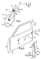
- FIG 1 With reference to figure 1 there is shown a latch bolt in a form of a claw 10 pivotable about a claw pin 12 between a closed position (as shown in figure 1) wherein a striker 14 is retained in a mouth 16 of the claw and an open position (not shown) wherein the striker is no longer retained in the mouth 16.
- a pawl 18 is further pivotable about a pawl pivot pin 20 between a retaining position (as shown in figure 1) wherein it prevents the claw from rotating in an anticlockwise direction as shown in figure 1 thus securing the striker 14, to a released position wherein the pawl no longer contacts the claw, thus allowing the claw to rotate in an anticlockwise direction as shown in figure 1 thus releasing the striker.
- the pawl 18 is pivotally mounted on the pawl pivot pin by a rotating element bearing shown generally as item 22.
- the rotating element bearing comprises an outer race 24 which is integral with the pawl 18, rotating elements 26 in this case being needle rollers, and an inner race 28 being integral with the pawl pivot pin 20.
- the rotating elements could be of another form, such as ball bearings or roller bearings.
- a separate outer bearing race could be provided which is rotationally secured in a hole of the pawl for example by an interference press fit.
- a separate inner race could be provided which is rotationally secured to the pawl pivot pin, for example by an interference press fit.
- the pawl is connected to a power actuator 30 (shown schematically) via a connection means 32 (again shown schematically). Operation of the power actuator moves the pawl from its retained position to its release position thereby allowing release of the striker.
- Latch assembly 36 includes a latch bolt 40 and a pawl 42, operation of which is similar to claw 10 and pawl 18 as described above.
- pawl 42 is mounted by a plain bearing arrangement on pawl pivot pin 44.
- the latch arrangement further includes an inside door handle 38 which is connected to pawl 42 by a transmission path 46 (only part of which is shown).
- Transmission path 46 includes a rod 48 which connects the inside door handle to an inside release lever 50 (also of the transmission path).
- release lever is to be understood as a lever which is situated in a transmission path between an inside door handle and the pawl but which is not in the transmission path between an outside door handle and a pawl.
- Inside release lever 50 includes an array of teeth 52 which are engagable with an array of teeth 54 of a latch release lever 56 pivotally mounted on the latch assembly 36.
- latch release lever refers to a lever which is situated in a transmission path between an inside handle and the pawl, and is also in the transmission path between an outside handle and the pawl.
- An outside door handle (not shown) has a transmission path which acts in the direction of arrow D on end 56A of latch release lever 56 thus also causing the claw 40 to release the striker.
- latch arrangement 34 is mounted on a door 58 of a vehicle 60 (only part of which is shown).
- the door defines a major plain which is substantially parallel to the plain defined by the X and Z axes.
- the inside release lever 50 is pivotable about an axis substantially parallel to the Y axis.
- Figure 2A shows a cross section view of door 58.
- door 58 has an inner skin 58A and an outer skin 58B.
- the door is pivoted about effective pivot point P.
- the latch assembly 36 is mounted on a rear face 62 of the door and a line L joining effective pivot point P with latch assembly 36 is perpendicular to the plane of rear face 62.
- the angle between the door inner skin and the rear face may vary.
- the angle may be 110° and similarly the angle between the axis of rotation of the inside release lever and latch release lever can be up to 110°.
- the axis of rotation of the inside release lever intersects the axis of rotation of latch release lever, but this need not be the case.
- these axes it is possible for these axes to be skew relative to each other whilst the first and second gear teeth can still co-operate to open the latch.
- the arrays of teeth 52 and 54 are of involute bevel form.
- the bevel involute surfaces of the teeth mesh together and during at least part of the opening movement of the inside release handle a rolling action occurs between the contacting involute bevel teeth.
- This rolling action significantly reduces friction between the inside release lever 50 and the latch release lever 56 thus enabling the door to be opened more easily.
- the power actuator can act through the gear teeth.
Landscapes
- Lock And Its Accessories (AREA)
Abstract
Description
Claims (19)
- A latch assembly including a latch bolt moveable between a closed position at which it is capable of retaining a striker and a open position at which it is capable of releasing a striker, the latch assembly further including a pawl moveable between a retaining position at which it is capable of retaining the latch bolt in at least its closed position and a released position at which the latch bolt is free to move between its open and closed position, in which the pawl is rotatably mounted via a rotating element bearing.
- A latch assembly as defined in Claim 1 in which the rotating element bearing includes needle roller rotating elements.
- A latch assembly as defined in Claim 1 or 2 in which the rotating element bearing includes an outer race which is integral with the pawl.
- A latch assembly as defined in any one of Claims 1 to 3 in which the rotating element bearing includes an inner race which is integral with a pawl pivot pin.
- A latch assembly as defined in any preceding claim further including a power actuator operable to move the pawl to its released position.
- A latch assembly including a first release lever being pivotable about a first axis and having plurality of first gear teeth and a second release lever being pivotable about second axis and having a plurality of second gear teeth for co-operation with the plurality of first gear teeth, operation of the first release lever causing the second release lever to unlatch the latch in which the first axis is not parallel to the second axis.
- A latch assembly as defined in claim 6 in which the first axis is angled between 70° and 110° relative to the second axis.
- A latch assembly as defined in claim 6 in which the first axis is substantially perpendicular to the second axis.
- A latch assembly as defined in claim 6 in which the first axis is skew relative to the second axis.
- A latch assembly as defined in claims 6 to 9 in which the plurality of first gear teeth have a substantially involute form.
- A latch assembly as defined in claims 6 to 10 in which the plurality of second gear teeth have a substantially involute gear form.
- A latch assembly as defined in claims 6 to 11 in which the first release lever is an inside release lever.
- A latch assembly as defined in claim 12 in which the first axis is substantially perpendicular to a major plane of an associated door.
- A latch assembly as defined in claims 6 to 13 in which the second release lever is a latch release lever.
- A latch assembly as defined in claim 14 in which the second axis lies in a major plane of an associated door.
- A latch assembly as defined in claim 15 in which the second axis is substantially horizontal.
- A latch assembly as defined in claims 13 or 16 in which the second axis lies substantially in a fore and aft direction of an associated door.
- A latch assembly as defined in claims 6 to 14 in which the plurality of first gear teeth and the plurality of second gear teeth provide a bevel gear arrangement.
- A latch assembly as defined in claims 6 to 18 further including a latch bolt moveable between a close position at which it is capable of retaining a striker and an open position at which it is capable of releasing a striker, a latch assembly further including a pawl moveable between a retaining position at which it is capable of retaining latch bolt in at least is closed position and a released position at which the latch bolt is free to move between its open and closed position, in which the latch assembly further includes a power actuator operable to move the pawl to its released position.
Applications Claiming Priority (2)
| Application Number | Priority Date | Filing Date | Title |
|---|---|---|---|
| GB0011456A GB0011456D0 (en) | 2000-05-13 | 2000-05-13 | Latch assembly and latch arrangement |
| GB0011456 | 2000-05-13 |
Publications (3)
| Publication Number | Publication Date |
|---|---|
| EP1154106A2 true EP1154106A2 (en) | 2001-11-14 |
| EP1154106A3 EP1154106A3 (en) | 2002-03-27 |
| EP1154106B1 EP1154106B1 (en) | 2005-06-29 |
Family
ID=9891452
Family Applications (1)
| Application Number | Title | Priority Date | Filing Date |
|---|---|---|---|
| EP20010304266 Expired - Lifetime EP1154106B1 (en) | 2000-05-13 | 2001-05-14 | Latch assembly |
Country Status (4)
| Country | Link |
|---|---|
| US (1) | US6568721B2 (en) |
| EP (1) | EP1154106B1 (en) |
| DE (1) | DE60111679T2 (en) |
| GB (1) | GB0011456D0 (en) |
Cited By (1)
| Publication number | Priority date | Publication date | Assignee | Title |
|---|---|---|---|---|
| WO2008102097A1 (en) | 2007-02-23 | 2008-08-28 | Meritor Technology, Inc. | Latch assembly |
Families Citing this family (2)
| Publication number | Priority date | Publication date | Assignee | Title |
|---|---|---|---|---|
| GB0121066D0 (en) * | 2001-08-31 | 2001-10-24 | Meritor Light Vehicle Sys Ltd | Door latch arrangement |
| JP6171211B2 (en) * | 2013-01-16 | 2017-08-02 | キーケルト アクツィーエンゲゼルシャフト | Car door latch |
Family Cites Families (11)
| Publication number | Priority date | Publication date | Assignee | Title |
|---|---|---|---|---|
| US4390197A (en) * | 1981-09-28 | 1983-06-28 | Scovill Inc. | Electrically controlled latch |
| DE3902645A1 (en) * | 1989-01-30 | 1990-08-02 | Scharwaechter Gmbh Co Kg | DOOR FASTENER FOR MOTOR VEHICLE DOORS |
| US4973091A (en) * | 1989-09-20 | 1990-11-27 | Truth Incorporated | Sliding patio door dual point latch and lock |
| US5090750A (en) * | 1991-01-03 | 1992-02-25 | Fixfabriken Ab | Locking mechanism for sash type windows |
| US5305969A (en) * | 1991-07-16 | 1994-04-26 | The Boeing Company | Aircraft door latch lock mechanism |
| DE69427302T2 (en) | 1993-09-30 | 2001-12-06 | Rockwell International Corp., Troy | LOCK LOCK FOR LOCKABLE BODY PART |
| US5618069A (en) * | 1995-07-21 | 1997-04-08 | General Motors Corporation | Hood and decklid latch assemblies |
| JP3214374B2 (en) | 1996-11-01 | 2001-10-02 | 日本鋼管株式会社 | Continuous casting of steel |
| JP2937256B2 (en) * | 1997-05-12 | 1999-08-23 | タキゲン製造株式会社 | Lock handle device for detachable door |
| ATE280296T1 (en) | 1997-08-21 | 2004-11-15 | Intier Automotive Closures Inc | MOTOR VEHICLE LOCK WITH REDUCED UNLOCKING FORCE |
| FR2782110B1 (en) | 1998-08-05 | 2000-10-06 | Valeo Securite Habitacle | ELECTRICALLY ASSISTED DOOR LOCK |
-
2000
- 2000-05-13 GB GB0011456A patent/GB0011456D0/en not_active Ceased
-
2001
- 2001-05-11 US US09/853,330 patent/US6568721B2/en not_active Expired - Fee Related
- 2001-05-14 EP EP20010304266 patent/EP1154106B1/en not_active Expired - Lifetime
- 2001-05-14 DE DE2001611679 patent/DE60111679T2/en not_active Expired - Fee Related
Cited By (3)
| Publication number | Priority date | Publication date | Assignee | Title |
|---|---|---|---|---|
| WO2008102097A1 (en) | 2007-02-23 | 2008-08-28 | Meritor Technology, Inc. | Latch assembly |
| US9279277B2 (en) | 2007-02-23 | 2016-03-08 | Inteva Products USA, LLC | Latch assembly |
| US10113342B2 (en) | 2007-02-23 | 2018-10-30 | Inteva Products, Llc | Latch assembly |
Also Published As
| Publication number | Publication date |
|---|---|
| DE60111679D1 (en) | 2005-08-04 |
| EP1154106A3 (en) | 2002-03-27 |
| DE60111679T2 (en) | 2006-05-04 |
| GB0011456D0 (en) | 2000-06-28 |
| US6568721B2 (en) | 2003-05-27 |
| US20010050485A1 (en) | 2001-12-13 |
| EP1154106B1 (en) | 2005-06-29 |
Similar Documents
| Publication | Publication Date | Title |
|---|---|---|
| EP2113048B1 (en) | Latch assembly | |
| US6007122A (en) | Outside door-handle | |
| CA2539529C (en) | Lock assembly | |
| EP1253268A2 (en) | Latch assembly | |
| US6123370A (en) | Increased strength dogging mechanism | |
| CN102015409B (en) | Interlocks for swing-out doors | |
| CN102858567A (en) | Vehicle door latch | |
| EP1154106B1 (en) | Latch assembly | |
| US20170298657A1 (en) | Dual cable door latch release mechanism | |
| US7147257B2 (en) | Striker assembly with lever | |
| CN115071382A (en) | Sliding door structure | |
| US7040687B2 (en) | Construction machine with door locking device | |
| US20220154514A1 (en) | Single drive system for driving multiple driven assemblies | |
| US20050179265A1 (en) | Motor-vehicle door latch | |
| GB2342383A (en) | Vehicle door latch with a lock link which engages a pawl lifter and release lever during door unlocking | |
| JPH0355374A (en) | Locking device for locking member of vehicle | |
| CN114096728A (en) | Door lock, in particular motor vehicle door lock | |
| CN223398525U (en) | Door lock for vehicle | |
| JP4118648B2 (en) | Vehicle door coupling device | |
| US12529249B2 (en) | Lock for a motor vehicle | |
| WO2023195124A1 (en) | Elevator door device and elevator | |
| CN121794438A (en) | Lock for a motor vehicle | |
| JP2001113946A (en) | Cab of construction machinery | |
| JP4285173B2 (en) | Gate opening / closing mechanism | |
| EP3839181A1 (en) | Latch assembly |
Legal Events
| Date | Code | Title | Description |
|---|---|---|---|
| PUAI | Public reference made under article 153(3) epc to a published international application that has entered the european phase |
Free format text: ORIGINAL CODE: 0009012 |
|
| AK | Designated contracting states |
Kind code of ref document: A2 Designated state(s): AT BE CH CY DE DK ES FI FR GB GR IE IT LI LU MC NL PT SE TR Kind code of ref document: A2 Designated state(s): DE ES FR GB IT |
|
| AX | Request for extension of the european patent |
Free format text: AL;LT;LV;MK;RO;SI |
|
| PUAL | Search report despatched |
Free format text: ORIGINAL CODE: 0009013 |
|
| AK | Designated contracting states |
Kind code of ref document: A3 Designated state(s): AT BE CH CY DE DK ES FI FR GB GR IE IT LI LU MC NL PT SE TR |
|
| AX | Request for extension of the european patent |
Free format text: AL;LT;LV;MK;RO;SI |
|
| 17P | Request for examination filed |
Effective date: 20020516 |
|
| RAP1 | Party data changed (applicant data changed or rights of an application transferred) |
Owner name: ARVINMERITOR LIGHT VEHICLE SYSTEMS (UK) LTD |
|
| AKX | Designation fees paid |
Free format text: DE ES FR GB IT |
|
| 17Q | First examination report despatched |
Effective date: 20040608 |
|
| GRAP | Despatch of communication of intention to grant a patent |
Free format text: ORIGINAL CODE: EPIDOSNIGR1 |
|
| GRAS | Grant fee paid |
Free format text: ORIGINAL CODE: EPIDOSNIGR3 |
|
| GRAA | (expected) grant |
Free format text: ORIGINAL CODE: 0009210 |
|
| AK | Designated contracting states |
Kind code of ref document: B1 Designated state(s): DE ES FR GB IT |
|
| PG25 | Lapsed in a contracting state [announced via postgrant information from national office to epo] |
Ref country code: IT Free format text: LAPSE BECAUSE OF FAILURE TO SUBMIT A TRANSLATION OF THE DESCRIPTION OR TO PAY THE FEE WITHIN THE PRESCRIBED TIME-LIMIT;WARNING: LAPSES OF ITALIAN PATENTS WITH EFFECTIVE DATE BEFORE 2007 MAY HAVE OCCURRED AT ANY TIME BEFORE 2007. THE CORRECT EFFECTIVE DATE MAY BE DIFFERENT FROM THE ONE RECORDED. Effective date: 20050629 |
|
| REG | Reference to a national code |
Ref country code: GB Ref legal event code: FG4D |
|
| REF | Corresponds to: |
Ref document number: 60111679 Country of ref document: DE Date of ref document: 20050804 Kind code of ref document: P |
|
| PG25 | Lapsed in a contracting state [announced via postgrant information from national office to epo] |
Ref country code: ES Free format text: LAPSE BECAUSE OF FAILURE TO SUBMIT A TRANSLATION OF THE DESCRIPTION OR TO PAY THE FEE WITHIN THE PRESCRIBED TIME-LIMIT Effective date: 20051010 |
|
| ET | Fr: translation filed | ||
| PLBE | No opposition filed within time limit |
Free format text: ORIGINAL CODE: 0009261 |
|
| STAA | Information on the status of an ep patent application or granted ep patent |
Free format text: STATUS: NO OPPOSITION FILED WITHIN TIME LIMIT |
|
| PG25 | Lapsed in a contracting state [announced via postgrant information from national office to epo] |
Ref country code: GB Free format text: LAPSE BECAUSE OF NON-PAYMENT OF DUE FEES Effective date: 20060514 |
|
| 26N | No opposition filed |
Effective date: 20060330 |
|
| PG25 | Lapsed in a contracting state [announced via postgrant information from national office to epo] |
Ref country code: DE Free format text: LAPSE BECAUSE OF NON-PAYMENT OF DUE FEES Effective date: 20061201 |
|
| GBPC | Gb: european patent ceased through non-payment of renewal fee |
Effective date: 20060514 |
|
| REG | Reference to a national code |
Ref country code: FR Ref legal event code: ST Effective date: 20070131 |
|
| PG25 | Lapsed in a contracting state [announced via postgrant information from national office to epo] |
Ref country code: FR Free format text: LAPSE BECAUSE OF NON-PAYMENT OF DUE FEES Effective date: 20060531 |
|
| REG | Reference to a national code |
Ref country code: GB Ref legal event code: 732E |