EP1153818A2 - Fluid controller and fluid meter bypass arrangement - Google Patents
Fluid controller and fluid meter bypass arrangement Download PDFInfo
- Publication number
- EP1153818A2 EP1153818A2 EP01111456A EP01111456A EP1153818A2 EP 1153818 A2 EP1153818 A2 EP 1153818A2 EP 01111456 A EP01111456 A EP 01111456A EP 01111456 A EP01111456 A EP 01111456A EP 1153818 A2 EP1153818 A2 EP 1153818A2
- Authority
- EP
- European Patent Office
- Prior art keywords
- fluid
- controller
- valve
- flow
- valve means
- Prior art date
- Legal status (The legal status is an assumption and is not a legal conclusion. Google has not performed a legal analysis and makes no representation as to the accuracy of the status listed.)
- Granted
Links
Images


Classifications
-
- B—PERFORMING OPERATIONS; TRANSPORTING
- B62—LAND VEHICLES FOR TRAVELLING OTHERWISE THAN ON RAILS
- B62D—MOTOR VEHICLES; TRAILERS
- B62D5/00—Power-assisted or power-driven steering
- B62D5/06—Power-assisted or power-driven steering fluid, i.e. using a pressurised fluid for most or all the force required for steering a vehicle
-
- B—PERFORMING OPERATIONS; TRANSPORTING
- B62—LAND VEHICLES FOR TRAVELLING OTHERWISE THAN ON RAILS
- B62D—MOTOR VEHICLES; TRAILERS
- B62D5/00—Power-assisted or power-driven steering
- B62D5/06—Power-assisted or power-driven steering fluid, i.e. using a pressurised fluid for most or all the force required for steering a vehicle
- B62D5/08—Power-assisted or power-driven steering fluid, i.e. using a pressurised fluid for most or all the force required for steering a vehicle characterised by type of steering valve used
- B62D5/087—Sliding spool valves
-
- B—PERFORMING OPERATIONS; TRANSPORTING
- B62—LAND VEHICLES FOR TRAVELLING OTHERWISE THAN ON RAILS
- B62D—MOTOR VEHICLES; TRAILERS
- B62D5/00—Power-assisted or power-driven steering
- B62D5/06—Power-assisted or power-driven steering fluid, i.e. using a pressurised fluid for most or all the force required for steering a vehicle
- B62D5/09—Power-assisted or power-driven steering fluid, i.e. using a pressurised fluid for most or all the force required for steering a vehicle characterised by means for actuating valves
-
- F—MECHANICAL ENGINEERING; LIGHTING; HEATING; WEAPONS; BLASTING
- F16—ENGINEERING ELEMENTS AND UNITS; GENERAL MEASURES FOR PRODUCING AND MAINTAINING EFFECTIVE FUNCTIONING OF MACHINES OR INSTALLATIONS; THERMAL INSULATION IN GENERAL
- F16D—COUPLINGS FOR TRANSMITTING ROTATION; CLUTCHES; BRAKES
- F16D31/00—Fluid couplings or clutches with pumping sets of the volumetric type, i.e. in the case of liquid passing a predetermined volume per revolution
- F16D31/02—Fluid couplings or clutches with pumping sets of the volumetric type, i.e. in the case of liquid passing a predetermined volume per revolution using pumps with pistons or plungers working in cylinders
Definitions
- the present invention relates to fluid controllers of the type used to control the flow of fluid from a source of pressurized fluid to a fluid pressure actuated device, such as a steering cylinder for steering a vehicle. More particularly, the present invention relates to such a fluid controller having at least two different modes of operation, in terms of the relationship between the manual input to the fluid controller and the rate of fluid flow out of the controller.
- a conventional fluid controller of the type to which the present invention relates includes a housing which defines various fluid ports, and further includes a fluid meter, a valve means defining a main fluid path, and an arrangement for imparting follow-up movement to the valve means, in response to the flow of fluid through the fluid meter.
- the flow through the controller valve means is directly proportional to the areas of the variable flow control orifices in the main fluid path. As is well know to those skilled in the art, the area of each flow control orifice is, in turn, typically proportional to the rate at which the steering wheel is rotated.
- a typical application for a full-fluid-linked steering controller of the type to which the present invention relates would be a vehicle such as is used on a work site, and such a vehicle would be used in one of two operating modes.
- the vehicle may be operated in a "roading" mode, i.e., it is driven on the road, at normal roading speeds, in order to reach a work site.
- the vehicle may be operated in a "working" mode, at the work site and is performing work related operations, such as moving a pile of dirt, etc., during which the vehicle is moving at relatively slow speeds.
- the term "gain rate” refers to the rate of change of steered wheel position for a given amount of steering input (such as, but not limited to, rotation of a vehicle steering wheel).
- the gain rate is actually a constant, and as a result, the amount of steering motion by the vehicle operator while roading is typically acceptable, but the amount of steering motion required at the work site, over the course of a typical workday, can cause excessive operator fatigue.
- One approach to providing a steering system which gives the operator separate roading and working modes of operation has been to provide the vehicle operator with a steering wheel for use when the vehicle needs to be in the roading mode, and with a joy stick for use when the vehicle needs to be in the working mode.
- the steering wheel gives the operator somewhat the same feel as driving an automobile, which is desirable for the roading mode, while the joy stick may be used to provide relatively large steering changes with relatively little operator input (a large gain rate), which is desirable for use in the working mode.
- the above and other objects of the invention are accomplished by the provision of an improved fluid controller operable to control the flow of fluid from a source of pressurized fluid to a fluid pressure operated device.
- the controller includes housing means defining an inlet port for connection to the source of fluid, and first and second control fluid ports for connection to the fluid pressure operated device.
- Controller valve means is disposed in the housing means and defines a neutral position, and at least one operating position in which the housing means and the controller valve means cooperate to define a main fluid path providing fluid communication from the inlet port to the first control fluid port and including a fluid actuated means for imparting follow-up movement to the controller valve means generally proportional to the volume of fluid flow through the main fluid path when the controller valve means is in the operating position.
- the fluid actuated means includes a rotatable measuring member providing the follow-up movement.
- the improved fluid controller is characterized by selector valve means disposed in series flow relationship in the main fluid path, between the fluid inlet port and the fluid actuated means and operable, in a first position to permit normal flow through the main fluid path.
- the selector valve means is operable in a second position to block fluid flow through the fluid actuated means while bypassing the fluid actuated means, thus permitting flow through the main fluid path, but preventing the follow-up movement to the controller valve means.
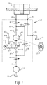
- FIG. 1 is a somewhat simplified hydraulic schematic of a hydrostatic power steering system including a fluid controller made in accordance with the present invention.
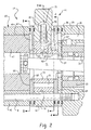
- FIG. 2 is a fragmentary, axial cross-section of one portion of the fluid controller shown schematically in FIG. 1.
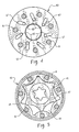
- FIG. 3 is a transverse cross-section, taken on line 3-3 of FIG. 2, and on a smaller scale than FIG. 2.
- FIG. 4 is a transverse cross-section, taken on line 4-4 of FIG. 2, and on a somewhat smaller scale than FIG. 3.
- FIG. 5 is a transverse cross-section, taken on line 5-5 of FIG. 2, and on the same scale as FIG. 4.
- FIG. 6 is a graph of Flow, as a percent of maximum possible flow, versus Steering Wheel Rotation (in degrees) to accomplish the particular flow in one second, comparing the two operating modes of the present invention.
- FIG. 1 is a somewhat simplified hydraulic schematic of a vehicle hydrostatic power steering system including a fluid controller made in accordance with the teachings of the present invention.
- the system includes a fluid pump 11, shown herein as a fixed displacement pump, having its inlet connected to a system reservoir 13. The output of the pump 11 is communicated to an inlet port 15 of a fluid controller, generally designated 17.
- the fluid controller 17 controls the flow of fluid from the pump 11 to a steering cylinder 19, or some other suitable fluid pressure operated steering actuator or device.
- the fluid controller 17 includes a pair of control (cylinder) fluid ports 21 and 23 which are connected to the opposite ends of the steering cylinder 19.
- the fluid controller 17 also includes a return port 25 which returns fluid to the reservoir 13.
- the fluid controller 17 is preferably made in accordance with the teachings of U.S. Patent Nos. 4,759,182 and 5,080,135, both of which are assigned to the assignee of the present invention and incorporated herein by reference.
- the fluid controller 17 is operated by means of only a single steering input, shown herein schematically in FIG. 1 as being a conventional steering wheel 27, although it should be understood by those skilled in the art that the invention is not limited to use with a steering wheel, and the steering input device could take various other forms, all of which would be within the scope of the present invention.
- the present invention makes it possible, and it is quite desirable to use only a single steering input device, and avoid the complication and expense of multiple steering input devices.
- the fluid controller 17 includes a valve housing 29, and disposed therein is the controller valving.
- the controller valving includes a primary valve member 31, also referred to hereinafter as the "spool valve”, and a follow-up valve member 33, also referred to hereinafter as the "sleeve valve”.
- the valve housing 29 defines a plurality of meter passages 35, the function of which is well know to those skilled in the art, but which will be described briefly subsequently.
- port plate 37 Disposed adjacent the valve housing 29 is port plate 37 which defines a plurality of ports 39, with one port 39 being disposed at the end of, and in open communication with, each of the meter passages 35.
- the spool valve 31 and the sleeve valve 33 incorporate the "wide angle" feature of the above-incorporated U.S. Patent No. 5,080,135.
- wide angle it is meant that the various flow control orifices defined by the spool valve and sleeve valve do not reach their maximum orifice areas until the relative displacement (deflection) between the spool valve and sleeve valve is on the order of about thirty-five to forty-five or fifty degrees, rather than the ten to twenty degree maximum deflection conventional in many fluid controllers.
- selector valve section 41 Disposed rearwardly of the port plate 37 is a selector valve section, generally designated 41, which will be described in greater detail subsequently.
- the selector valve section 41 is shown schematically in FIG. 1 as a two-position, three-way, pressure pilot operated flow control valve.
- a fluid meter Disposed rearwardly (to the left in FIG. 2) of the selector valve section 41 is a fluid meter, generally designated 43 (also shown schematically in FIG. 1).
- the fluid meter 43 includes an internally toothed ring member 45, and disposed eccentrically within the ring member 45 is an externally toothed star member 47.
- the internal and external teeth of the ring member 45 and star member 47 cooperate to define a plurality of expanding and contracting fluid volume chambers 49 (shown best in FIG. 5).
- the star 47 orbits and rotates within the ring 45, and as a result of such orbital and rotational movement, metered fluid is then communicated from the contracting volume chambers.
- the fluid meter 43 measures (or “meters") the fluid which flows therethrough, and in addition, provides an output motion (i.e., the orbital and rotational motion of the star 47) which is proportional to the fluid flow through the fluid meter 43.
- the output motion of the star 47 is communicated by means of a drive shaft 51 and is transmitted, in a manner not shown herein, but shown in the above-incorporated patents, into follow-up movement.
- This follow-up movement is transmitted to the follow-up valve member 33, tending to return the valve member 33 to a neutral position, relative to the primary valve member 31 at the completion of a steering operation.
- What has been described above is part of the operation when the fluid controller 17 is operating in its normal, roading mode, which occurs when the selector valve section 41 is in the condition, designated "R" shown schematically in FIG. 1.
- the main fluid path 53 includes a series of flow control orifices, and in the subject embodiment, some are fixed orifices, and some are variable orifices (i.e., the flow area through the orifice varies in proportion to the relative displacement of the spool 31 and sleeve 33).
- the fluid controller 17 is preferably of the type having, in parallel with the main fluid path 53, an amplification fluid path 55, including a variable amplification orifice 57.
- both the amplification fluid path 55 and the variable amplification orifice 57 are defined primarily by the spool valve 31 and the sleeve valve 33, in accordance with the teachings of the above-incorporated U.S. Patent No. 4,759,182.
- the amplification fluid path 55 communicates with (receives fluid from) the main fluid path 53 just downstream of the main flow control orifice A1, and then again communicates with (flows into) the main fluid path 53 just upstream of the flow control orifice A4.
- the main purpose of the amplification fluid path 55 is to "amplify" the flow through the fluid meter 43, i.e., communicate a greater total flow to the steering cylinder 19 than the size of the fluid meter 43 would, in and of itself permit.
- the selector valve section 41 includes a selector valve housing 61, and on either axial end of the housing 61, a spacer plate 63.
- the spacer plate 63 disposed adjacent the port plate 37 will be referred to hereinafter as the forward spacer plate, while the spacer plate 63 adjacent the fluid meter 43 will be referred to hereinafter as the rearward spacer plate.
- the two spacer plates 63 are substantially identical, thus reducing the total part count of the controller and simplifying assembly thereof.
- each of the meter passages 35 and ports 39 would, in a conventional fluid controller, be aligned with the respective fluid volume chamber 49.
- the selector valve section 41 is interposed between the port plate 37 and the fluid meter 43, both physically and in terms of fluid flow relationship. Therefore, the function of the spacer plates 63 is to "transport" fluid from the meter passages 35 and ports 37 radially inward to the selector valving (to be described subsequently), and then from the selector valving radially outward to the volume chambers 49.
- each spacer plate defines a plurality of through bores 65, and communicating with each bore 65 is an angled recess 67, formed in an axial end surface 69 of the spacer plate 63.
- the forward spacer plate 63 has the radially outer end of each recess 67 in communication with its respective port 39, whereas the rearward spacer plate 63 has the radially outer end of each recess 67 in communication with its respective volume chamber 49.
- the selector valve housing 61 defines a generally cylindrical valve chamber 71, and disposed within the chamber 71 is a rotatable, generally cylindrical selector valve 73. The valving action accomplished by the selector valve 73 will be described subsequently in detail.
- the selector valve housing 61 also defines a transverse bore 75, the left end of the bore 75 being provided with a fitting 77, and the right end of the bore 75 being provided with a fitting 79.
- the fittings 77 and 79 are shown in the schematic of FIG.
- the pilot piston 81 shifts to the right to the position shown in FIG. 3. Subsequently, if the pilot pressure in the fitting 77 is drained, and a pilot pressure is communicated through the fitting 79, the pilot piston 83 will be biased from the position shown in FIG. 3, rotating the selector valve 73 counter-clockwise about twenty degrees from the FIG. 3 position.
- the selector valve 73 defines a plurality of axial bores 91, the number of axial bores 91 being equal to the number of volume chambers 49, and also equal to the number of through bores 65 and recesses 67 in each spacer plate 63. Disposed adjacent each axial bore 91, the forward end surface of the selector valve 73 defines a shallow, radial recess 93. With the selector valve 73 in the rotational position shown in FIG. 3, each recess 93 is in communication with a shallow radial recess 95 formed in a forward axial face of the selector valve housing 61. The radial recesses 95 are each in open communication with an annular chamber 97, the function of which will be described subsequently.
- each through bore 65 in the forward spacer plate 63 is in communication with its respective axial bore 91.
- each bore 91 is also in communication with its respective through bore 65 in the rearward spacer plate 63.
- the deflection angle refers to the displacement between the spool valve 31 and sleeve valve 33 which, in turn, is a function of the rate of rotation of the steering wheel 27.
- fluid flows through the main fluid path 53 in the same manner as in any conventional fluid controller.
- the amplification flow path 55 there is the flow through the amplification flow path 55, such that the total flow to the steering cylinder 19 is the sum of the flows in the flow paths 53 and 55, as is well known already in the fluid controller art.
- each of the through bores 65 in the forward spacer plate 63 is in open communication with its respective radial recess 93, and in turn, each recess 93 communicates through its respective radial recess 95 with the annular chamber 97.
- the annular chamber 97 is shown schematically as a bypass path around the fluid meter 43.
- each axial bore 91 is out of communication with its respective through bores 65 in both the forward and rearward spacer plates 63, such that fluid in the axial bores 91 is simply trapped therein.
- each of the through bores 65 in the rearward spacer plate 63 has flow therethrough blocked by the adjacent axial end surface of the selector valve 73.
- the fluid controller While the fluid controller is operating in the working mode, fluid in each of the volume chambers 49, as well as fluid in each of the recesses 67 in the rearward spacer plate 63 is trapped.
- the star member 47 does not engage in its normal orbital and rotational movement, but instead, is effectively "fluid locked” and remains stationary. Thus, there is no follow-up movement transmitted from the star member 47 by the drive shaft 51 to the follow-up valve member 33.
- the size of each of the flow control orifices A1 through A5 is determined solely by the angle of deflection of the steering wheel 27 from its neutral position. It will be understood by those skilled in the art that the same torque is required to rotate the steering wheel 27 in either mode “R” or “W”, but when operating in the working mode, much less movement of the steering wheel is required, as is illustrated in the graph of FIG. 6, because of the absence of any follow-up movement back to the follow-up valve member 33. Instead, the unit operates in the manner of what is known as a "jerk-steer" controller having no fluid meter, in which rotation of the steering wheel merely opens up the valving orifices A1 through A5.
- a steering wheel displacement of about 50 degrees results in about the same flow rate (100 percent of maximum possible flow in FIG. 6) to the steering cylinder 19 as occurs when the fluid controller is in the roading mode, and the steering wheel is being rotated at about 120 rpm, to keep the spool valve 31 at the 50 degree deflection, relative to the sleeve valve 33.
- the operator must turn the steering wheel two turns (720 degrees) from the centered (neutral) position, and at a high rate of rotation (120 rpm), every time it is desired to make a major steering correction on a work site.
- the operator merely rotates the steering wheel by an angle equal to the desired spool-sleeve deflection (e.g., 50 degrees), and hold the wheel in that position until the desired movement of the steering cylinder 19 has occurred, then releases the steering wheel allowing it to re-center under the influence of the centering springs, shown in the above-incorporated patents.
- FIG. 6 is that it illustrates, pictorially, the decreased operator effort when operating in the working mode "W", as compared to the roading mode "R".
- the area under each of the graphs is representative of the steering effort required by the operator to achieve the particular flow, in one second.
Landscapes
- Engineering & Computer Science (AREA)
- Mechanical Engineering (AREA)
- Chemical & Material Sciences (AREA)
- Combustion & Propulsion (AREA)
- Transportation (AREA)
- General Engineering & Computer Science (AREA)
- Power Steering Mechanism (AREA)
- Steering Control In Accordance With Driving Conditions (AREA)
Abstract
Description
- The present invention relates to fluid controllers of the type used to control the flow of fluid from a source of pressurized fluid to a fluid pressure actuated device, such as a steering cylinder for steering a vehicle. More particularly, the present invention relates to such a fluid controller having at least two different modes of operation, in terms of the relationship between the manual input to the fluid controller and the rate of fluid flow out of the controller.
- Although the present invention may be used in connection with fluid controllers of many types, and having various constructions and applications, it is especially advantageous when used in conjunction with a full-fluid-linked steering controller, for use on a vehicle of primarily the "off highway" type, and will be described in connection therewith.
- A conventional fluid controller of the type to which the present invention relates includes a housing which defines various fluid ports, and further includes a fluid meter, a valve means defining a main fluid path, and an arrangement for imparting follow-up movement to the valve means, in response to the flow of fluid through the fluid meter. The flow through the controller valve means is directly proportional to the areas of the variable flow control orifices in the main fluid path. As is well know to those skilled in the art, the area of each flow control orifice is, in turn, typically proportional to the rate at which the steering wheel is rotated.
- A typical application for a full-fluid-linked steering controller of the type to which the present invention relates would be a vehicle such as is used on a work site, and such a vehicle would be used in one of two operating modes. First, the vehicle may be operated in a "roading" mode, i.e., it is driven on the road, at normal roading speeds, in order to reach a work site. Second, the vehicle may be operated in a "working" mode, at the work site and is performing work related operations, such as moving a pile of dirt, etc., during which the vehicle is moving at relatively slow speeds.
- The roading and working modes of operation described above present very different steering requirements, as is now well know to those skilled in the art. When roading the vehicle, a relatively low gain rate would be desirable, whereas, when operating in the working mode, a relatively high gain rate would be desirable. As used herein, the term "gain rate" refers to the rate of change of steered wheel position for a given amount of steering input (such as, but not limited to, rotation of a vehicle steering wheel). With a conventional full-fluid-linked steering controller, however, the gain rate is actually a constant, and as a result, the amount of steering motion by the vehicle operator while roading is typically acceptable, but the amount of steering motion required at the work site, over the course of a typical workday, can cause excessive operator fatigue.
- One approach to providing a steering system which gives the operator separate roading and working modes of operation has been to provide the vehicle operator with a steering wheel for use when the vehicle needs to be in the roading mode, and with a joy stick for use when the vehicle needs to be in the working mode. The steering wheel gives the operator somewhat the same feel as driving an automobile, which is desirable for the roading mode, while the joy stick may be used to provide relatively large steering changes with relatively little operator input (a large gain rate), which is desirable for use in the working mode.
- Unfortunately, the provision of a steering wheel/joy stick system adds substantially to the overall expense and complication of the system, in terms of the hardware involved, and also results in substantial complication and expense in order to coordinate the portion of the system operated by the steering wheel with the portion of the system operated by the joy stick.
- Accordingly, it is an object of the present invention to provide an improved fluid controller for use in a vehicle steering system which can provide both a roading mode and a working mode of operation, but which overcomes the disadvantages of the prior art described above.
- It is a more specific object of the present invention to provide such an improved fluid controller which can accomplish the above-stated object, while requiring only a single steering input device, thus overcoming the prior art disadvantage of the need to coordinate between two different steering inputs.
- It is still another object of the present invention to provide an improved steering system for a vehicle wherein both the roading mode and the working mode may be accomplished in a single fluid controller, thus overcoming the prior art disadvantage of excessive and complicated hardware.
- It is still a further object of the present invention to provide an improved fluid controller for use in a vehicle steering system, which greatly reduces the amount of operator steering motion when operating in the working mode.
- The above and other objects of the invention are accomplished by the provision of an improved fluid controller operable to control the flow of fluid from a source of pressurized fluid to a fluid pressure operated device. The controller includes housing means defining an inlet port for connection to the source of fluid, and first and second control fluid ports for connection to the fluid pressure operated device. Controller valve means is disposed in the housing means and defines a neutral position, and at least one operating position in which the housing means and the controller valve means cooperate to define a main fluid path providing fluid communication from the inlet port to the first control fluid port and including a fluid actuated means for imparting follow-up movement to the controller valve means generally proportional to the volume of fluid flow through the main fluid path when the controller valve means is in the operating position. The fluid actuated means includes a rotatable measuring member providing the follow-up movement.
- The improved fluid controller is characterized by selector valve means disposed in series flow relationship in the main fluid path, between the fluid inlet port and the fluid actuated means and operable, in a first position to permit normal flow through the main fluid path. The selector valve means is operable in a second position to block fluid flow through the fluid actuated means while bypassing the fluid actuated means, thus permitting flow through the main fluid path, but preventing the follow-up movement to the controller valve means.
- FIG. 1 is a somewhat simplified hydraulic schematic of a hydrostatic power steering system including a fluid controller made in accordance with the present invention.
- FIG. 2 is a fragmentary, axial cross-section of one portion of the fluid controller shown schematically in FIG. 1.
- FIG. 3 is a transverse cross-section, taken on line 3-3 of FIG. 2, and on a smaller scale than FIG. 2.
- FIG. 4 is a transverse cross-section, taken on line 4-4 of FIG. 2, and on a somewhat smaller scale than FIG. 3.
- FIG. 5 is a transverse cross-section, taken on line 5-5 of FIG. 2, and on the same scale as FIG. 4.
- FIG. 6 is a graph of Flow, as a percent of maximum possible flow, versus Steering Wheel Rotation (in degrees) to accomplish the particular flow in one second, comparing the two operating modes of the present invention.
- Referring now to the drawings, which are not intended to limit the invention, FIG. 1 is a somewhat simplified hydraulic schematic of a vehicle hydrostatic power steering system including a fluid controller made in accordance with the teachings of the present invention. The system includes a fluid pump 11, shown herein as a fixed displacement pump, having its inlet connected to a
system reservoir 13. The output of the pump 11 is communicated to aninlet port 15 of a fluid controller, generally designated 17. - Referring still to FIG. 1, the
fluid controller 17 controls the flow of fluid from the pump 11 to asteering cylinder 19, or some other suitable fluid pressure operated steering actuator or device. Thefluid controller 17 includes a pair of control (cylinder)fluid ports steering cylinder 19. Thefluid controller 17 also includes areturn port 25 which returns fluid to thereservoir 13. - The
fluid controller 17 is preferably made in accordance with the teachings of U.S. Patent Nos. 4,759,182 and 5,080,135, both of which are assigned to the assignee of the present invention and incorporated herein by reference. In accordance with one important aspect of the present invention, thefluid controller 17 is operated by means of only a single steering input, shown herein schematically in FIG. 1 as being aconventional steering wheel 27, although it should be understood by those skilled in the art that the invention is not limited to use with a steering wheel, and the steering input device could take various other forms, all of which would be within the scope of the present invention. However, the present invention makes it possible, and it is quite desirable to use only a single steering input device, and avoid the complication and expense of multiple steering input devices. - Referring now to FIG. 2, in conjunction with FIG. 1, the
fluid controller 17 includes avalve housing 29, and disposed therein is the controller valving. In the subject embodiment, and by way of example only, the controller valving includes aprimary valve member 31, also referred to hereinafter as the "spool valve", and a follow-upvalve member 33, also referred to hereinafter as the "sleeve valve". Thevalve housing 29 defines a plurality ofmeter passages 35, the function of which is well know to those skilled in the art, but which will be described briefly subsequently. Disposed adjacent thevalve housing 29 isport plate 37 which defines a plurality ofports 39, with oneport 39 being disposed at the end of, and in open communication with, each of themeter passages 35. Preferably, thespool valve 31 and thesleeve valve 33 incorporate the "wide angle" feature of the above-incorporated U.S. Patent No. 5,080,135. By wide angle, it is meant that the various flow control orifices defined by the spool valve and sleeve valve do not reach their maximum orifice areas until the relative displacement (deflection) between the spool valve and sleeve valve is on the order of about thirty-five to forty-five or fifty degrees, rather than the ten to twenty degree maximum deflection conventional in many fluid controllers. - Disposed rearwardly of the
port plate 37 is a selector valve section, generally designated 41, which will be described in greater detail subsequently. Theselector valve section 41 is shown schematically in FIG. 1 as a two-position, three-way, pressure pilot operated flow control valve. - Disposed rearwardly (to the left in FIG. 2) of the
selector valve section 41 is a fluid meter, generally designated 43 (also shown schematically in FIG. 1). As is well known in the art, thefluid meter 43 includes an internallytoothed ring member 45, and disposed eccentrically within thering member 45 is an externallytoothed star member 47. The internal and external teeth of thering member 45 andstar member 47, respectively, cooperate to define a plurality of expanding and contracting fluid volume chambers 49 (shown best in FIG. 5). As is also well known in the art, as unmetered fluid is communicated to the expanding volume chambers, thestar 47 orbits and rotates within thering 45, and as a result of such orbital and rotational movement, metered fluid is then communicated from the contracting volume chambers. In this way, thefluid meter 43 measures (or "meters") the fluid which flows therethrough, and in addition, provides an output motion (i.e., the orbital and rotational motion of the star 47) which is proportional to the fluid flow through thefluid meter 43. - As is also well know to those skilled in the fluid controller art, the output motion of the
star 47 is communicated by means of adrive shaft 51 and is transmitted, in a manner not shown herein, but shown in the above-incorporated patents, into follow-up movement. This follow-up movement is transmitted to the follow-upvalve member 33, tending to return thevalve member 33 to a neutral position, relative to theprimary valve member 31 at the completion of a steering operation. What has been described above is part of the operation when thefluid controller 17 is operating in its normal, roading mode, which occurs when theselector valve section 41 is in the condition, designated "R" shown schematically in FIG. 1. - In a conventional manner, the
fluid meter 43 and theselector valve section 41 are held in tight, sealing engagement with thevalve housing 29 andport plate 37 by means of a plurality of bolts B, only one of which is shown in FIG. 2, but all of which are shown in transverse cross-section in FIGS. 3, 4, and 5. - Referring again primarily to FIG. 1, when the
fluid controller 17 is operating in the normal, roading mode, rotation of thesteering wheel 27 by the vehicle operator displaces thespool valve 31, relative to thesleeve valve 33. This displacement ofspool valve 31 relative to thesleeve valve 33, opens up a main fluid path, generally designated 53 which provides communication from theinlet port 15 through thefluid meter 43 to thecontrol fluid port 21. The mainfluid path 53 includes a series of flow control orifices, and in the subject embodiment, some are fixed orifices, and some are variable orifices (i.e., the flow area through the orifice varies in proportion to the relative displacement of thespool 31 and sleeve 33). These orifices are well know to those skilled in the art, are not in and of themselves essential features of the invention, and therefore will not be described in detail. These flow control orifices are conventionally designated A1; A2; A3; A4; and A5. It should be noted in FIG. 1 that the A5 orifice is not actually part of what has been described as the mainfluid path 53, but instead, is part of the return path communicating between thecontrol fluid port 23 on the "return" side of thesteering cylinder 19, and thereturn port 25. Thus, references herein, and in the appended claims, to the "main fluid path" will be understood to mean and include either the path designated "53" in FIG. 1, or thepath 53 plus the return path from theport 23 to thereturn port 25. - In accordance with one important feature of the subject embodiment, the
fluid controller 17 is preferably of the type having, in parallel with the mainfluid path 53, anamplification fluid path 55, including avariable amplification orifice 57. As is now well know to those skilled in the art, both theamplification fluid path 55 and thevariable amplification orifice 57 are defined primarily by thespool valve 31 and thesleeve valve 33, in accordance with the teachings of the above-incorporated U.S. Patent No. 4,759,182. Although not essential to the present invention, theamplification fluid path 55 communicates with (receives fluid from) the mainfluid path 53 just downstream of the main flow control orifice A1, and then again communicates with (flows into) the mainfluid path 53 just upstream of the flow control orifice A4. The main purpose of theamplification fluid path 55 is to "amplify" the flow through thefluid meter 43, i.e., communicate a greater total flow to thesteering cylinder 19 than the size of thefluid meter 43 would, in and of itself permit. - Referring now primarily to FIGS. 2, 3 and 4, the
selector valve section 41 includes aselector valve housing 61, and on either axial end of thehousing 61, aspacer plate 63. Thespacer plate 63 disposed adjacent theport plate 37 will be referred to hereinafter as the forward spacer plate, while thespacer plate 63 adjacent thefluid meter 43 will be referred to hereinafter as the rearward spacer plate. Preferably, the twospacer plates 63 are substantially identical, thus reducing the total part count of the controller and simplifying assembly thereof. As will be understood by those skilled in the fluid controller art, each of themeter passages 35 andports 39 would, in a conventional fluid controller, be aligned with the respectivefluid volume chamber 49. Theselector valve section 41 is interposed between theport plate 37 and thefluid meter 43, both physically and in terms of fluid flow relationship. Therefore, the function of thespacer plates 63 is to "transport" fluid from themeter passages 35 andports 37 radially inward to the selector valving (to be described subsequently), and then from the selector valving radially outward to thevolume chambers 49. - Referring now primarily to FIG. 4, each spacer plate defines a plurality of through
bores 65, and communicating with each bore 65 is anangled recess 67, formed in anaxial end surface 69 of thespacer plate 63. Theforward spacer plate 63 has the radially outer end of eachrecess 67 in communication with itsrespective port 39, whereas therearward spacer plate 63 has the radially outer end of eachrecess 67 in communication with itsrespective volume chamber 49. - Referring now primarily to FIG. 3, in which the
drive shaft 51 is omitted from the view, theselector valve housing 61 defines a generallycylindrical valve chamber 71, and disposed within thechamber 71 is a rotatable, generallycylindrical selector valve 73. The valving action accomplished by theselector valve 73 will be described subsequently in detail. Theselector valve housing 61 also defines atransverse bore 75, the left end of thebore 75 being provided with a fitting 77, and the right end of thebore 75 being provided with a fitting 79. As will be understood by those skilled in the art of hydraulic controls (pilot controls), thefittings selector valve 73 is piloted or shifted between its two, discrete operating positions shown in FIG. 1 and to be described in greater detail subsequently. Disposed within the transverse bore 75 is a pair ofpilot pistons pistons lever member 85 which is received within a bore 87 (see FIG. 2) formed in theselector valve 73. - Thus, when pilot pressure is communicated through the fitting 77, and drained from the fitting 79, the
pilot piston 81 shifts to the right to the position shown in FIG. 3. Subsequently, if the pilot pressure in the fitting 77 is drained, and a pilot pressure is communicated through the fitting 79, thepilot piston 83 will be biased from the position shown in FIG. 3, rotating theselector valve 73 counter-clockwise about twenty degrees from the FIG. 3 position. - Referring now primarily to FIGS. 2 and 3, the
selector valve 73 defines a plurality ofaxial bores 91, the number ofaxial bores 91 being equal to the number ofvolume chambers 49, and also equal to the number of throughbores 65 and recesses 67 in eachspacer plate 63. Disposed adjacent eachaxial bore 91, the forward end surface of theselector valve 73 defines a shallow,radial recess 93. With theselector valve 73 in the rotational position shown in FIG. 3, eachrecess 93 is in communication with a shallowradial recess 95 formed in a forward axial face of theselector valve housing 61. The radial recesses 95 are each in open communication with anannular chamber 97, the function of which will be described subsequently. - When the vehicle operator wishes to be able to steer the vehicle in the normal roading mode, it is necessary to direct pilot pressure through the fitting 79, rotating the
selector valve 73 from the position shown in FIG. 3 in a counter-clockwise direction such that eachaxial bore 91 is moved counter-clockwise to the position occupied in FIG. 3 by the radially inner end of theadjacent recess 93. The position of theselector valve 73 just described corresponds to that shown schematically in FIG. 1, and designated "R". By comparing the shifted position of theselector valve 73 described above with FIG. 4, it may be seen that, in the normal, roading mode, each throughbore 65 in theforward spacer plate 63 is in communication with its respectiveaxial bore 91. At the same time, each bore 91 is also in communication with its respective throughbore 65 in therearward spacer plate 63. - Thus, with the
selector valve 73 shifted from the position shown in FIG. 3 to the normal, roading mode, unmetered fluid is communicated through certain of themeter passages 35, through theaxial bores 91 to the expandingvolume chambers 49, while at the same time, metered fluid is being communicated from thecontracting volume chambers 49 through the respectiveaxial bores 91, and to other of themeter passages 35. It should be understood that in the roading mode, the operation of thefluid controller 17 of the present invention is the same as if the entireselector valve section 41 were removed, and thefluid meter 43 were disposed immediately adjacent theport plate 37. - As is understood by those skilled in the art, in the normal steering mode "R", the deflection angle refers to the displacement between the
spool valve 31 andsleeve valve 33 which, in turn, is a function of the rate of rotation of thesteering wheel 27. As may best be seen in FIG. 1, in the normal, roading mode of operation, fluid flows through the mainfluid path 53 in the same manner as in any conventional fluid controller. At the same time, there is the flow through theamplification flow path 55, such that the total flow to thesteering cylinder 19 is the sum of the flows in theflow paths - When the vehicle operator wishes to steer the vehicle in the working mode, it is necessary to communicate pilot pressure through the fitting 77 to rotate the
selector valve 73 in a clockwise direction from that described previously, back to the working mode position shown in FIG. 3, i.e., the position designated "W" in FIG. 1. With theselector valve 73 in the working mode position, each of the through bores 65 in theforward spacer plate 63 is in open communication with its respectiveradial recess 93, and in turn, eachrecess 93 communicates through its respectiveradial recess 95 with theannular chamber 97. Note that in FIG. 1, theannular chamber 97 is shown schematically as a bypass path around thefluid meter 43. - With the
selector valve 73 in the working mode position "W" of FIG. 3, eachaxial bore 91 is out of communication with its respective throughbores 65 in both the forward andrearward spacer plates 63, such that fluid in the axial bores 91 is simply trapped therein. At the same time, each of the through bores 65 in therearward spacer plate 63 has flow therethrough blocked by the adjacent axial end surface of theselector valve 73. While the fluid controller is operating in the working mode, fluid in each of thevolume chambers 49, as well as fluid in each of therecesses 67 in therearward spacer plate 63 is trapped. As a result, thestar member 47 does not engage in its normal orbital and rotational movement, but instead, is effectively "fluid locked" and remains stationary. Thus, there is no follow-up movement transmitted from thestar member 47 by thedrive shaft 51 to the follow-upvalve member 33. - Therefore, when the
fluid controller 17 is operating in the working mode "W", the size of each of the flow control orifices A1 through A5 is determined solely by the angle of deflection of thesteering wheel 27 from its neutral position. It will be understood by those skilled in the art that the same torque is required to rotate thesteering wheel 27 in either mode "R" or "W", but when operating in the working mode, much less movement of the steering wheel is required, as is illustrated in the graph of FIG. 6, because of the absence of any follow-up movement back to the follow-upvalve member 33. Instead, the unit operates in the manner of what is known as a "jerk-steer" controller having no fluid meter, in which rotation of the steering wheel merely opens up the valving orifices A1 through A5. - By way of example only, and referring now also to FIG. 6, in the subject embodiment of the invention, when the fluid controller is in the working mode "W", a steering wheel displacement of about 50 degrees results in about the same flow rate (100 percent of maximum possible flow in FIG. 6) to the
steering cylinder 19 as occurs when the fluid controller is in the roading mode, and the steering wheel is being rotated at about 120 rpm, to keep thespool valve 31 at the 50 degree deflection, relative to thesleeve valve 33. Thus, with a typical, prior art fluid controller having about four turns (lock-to-lock) capability, the operator must turn the steering wheel two turns (720 degrees) from the centered (neutral) position, and at a high rate of rotation (120 rpm), every time it is desired to make a major steering correction on a work site. However, with the arrangement of the present invention, the operator merely rotates the steering wheel by an angle equal to the desired spool-sleeve deflection (e.g., 50 degrees), and hold the wheel in that position until the desired movement of thesteering cylinder 19 has occurred, then releases the steering wheel allowing it to re-center under the influence of the centering springs, shown in the above-incorporated patents. - As will be understood by those skilled in the art, in either mode of operation, the torque required to rotate the steering wheel is the same, because the torque to rotate the wheel is a function of the spring rate of the centering springs. However, with the invention, operation in the working mode "W" requires so much less arm motion by the operator (less rotation of the steering wheel) than was required with the prior art fluid controller (represented by the roading mode "R" in FIG. 6), resulting in much less fatigue for the operator, and enhanced operating efficiency. The decrease in operator effort may best be seen in FIG. 6, which is a graph of Flow (as a percent of maximum flow) versus Steering Wheel Rotation (in degrees) in one second to achieve the corresponding flow. The significance of the graph of FIG. 6 is that it illustrates, pictorially, the decreased operator effort when operating in the working mode "W", as compared to the roading mode "R". In the graph of FIG. 6, the area under each of the graphs is representative of the steering effort required by the operator to achieve the particular flow, in one second.
- The invention has been described in great detail in the foregoing specification, and it is believed that various alterations and modifications of the invention will become apparent to those skilled in the art from a reading and understanding of the specification. It is intended that all such alterations and modifications are included in the invention, insofar as they come within the scope of the appended claims.
Claims (8)
- A fluid controller (17) operable to control the flow of fluid from a source (11) of pressurized fluid to a fluid pressure operated device (19); said controller (17) including housing means (29) defining an inlet port (15) for connection to said source (11) of fluid, and first (21) and second (23) control fluid ports for connection to said fluid pressure operated device (19); controller valve means (31,33) disposed in said housing means (29) and defining a neutral position, and at least one operating position (FIG. 1) in which said housing means and said controller valve means cooperate to define a main fluid path (53) providing fluid communication from said inlet port (15) to said first control fluid port (21) and including a fluid actuated means (43) for imparting follow-up movement to said controller valve means (33) generally proportional to the volume of fluid flow through said main fluid path (53) when said controller valve means (31,33) is in said operating position, said fluid actuated means (43) including a rotatable measuring member (47) providing said follow-up movement; characterized by:(a) selector valve means (41,73) disposed in series flow relationship in said main fluid path (53), between said fluid inlet port (15) and said fluid actuated means (43) and operable, in a first position ("R" in FIG. 1) to permit normal flow through said main fluid path (53); and(b) said selector valve means (41,73) being operable, in a second position ("W" in FIG. 1 and FIGS. 2 and 3) to block fluid flow through said fluid actuated means (43) while bypassing (97) said fluid actuated means (43), thus permitting flow through said main fluid path (53) while preventing said follow-up movement to said controller valve means (31,33).
- A fluid controller (17) as claimed in claim 1, characterized by said controller valve means comprises a primary, rotatable valve member (31) and a relatively rotatable, follow-up valve member (33), said controller valve means defining said main fluid path (53) by rotation of said primary valve member (31), relative to said follow-up valve member (33).
- A fluid controller (17) as claimed in claim 2, characterized by said housing means (29) cooperating with said controller valve means (31,33) to define an amplification fluid path (55) including a variable amplification orifice (57), said variable amplification orifice (57) being variable, between a minimum flow area and a maximum flow area, in response to rotation of said primary valve member (31) relative to said follow-up valve member (33).
- A fluid controller (17) as claimed in claim 3, characterized by said amplification fluid path (55) being in fluid communication with, and receiving fluid from, said main fluid path (53) at a location upstream of said fluid actuated means (43), and being in fluid communication with, and directing fluid to, said main fluid path (53) at a location downstream of said fluid actuated means (43).
- A fluid controller (17) as claimed in claim 1, characterized by said fluid actuated means (43) comprises an internally-toothed ring member (45) and eccentrically disposed therein, an externally-toothed star member (47) comprising said rotatable measuring member.
- A fluid controller (17) as claimed in claim 1, characterized by said selector valve means (41,73) being operable, in said second position (FIG. 3) to provide direct, relatively unrestricted fluid communication of said main fluid path (53), upstream of said fluid actuated means (43) with said main fluid path (53), downstream of said fluid actuated means (43).
- A fluid controller (17) as claimed in claim 5, characterized by said selector valve means (41,73) being disposed, physically, between said controller valve means (31,33) and said ring member (45) and said star member (47) of said fluid actuated means (43).
- A fluid controller (17) as claimed in claim 1 characterized by said selector valve means (41) comprises a rotatable selector valve (73) including fluid pressure actuated means (81,83,85) operable to rotate said selector valve (73) between said first ("R" in FIG. 1) and second ("W" in FIG. 1) positions, in response to a pilot pressure being communicated to a first (79) or a second (77) location in said valve means (41).
Applications Claiming Priority (2)
| Application Number | Priority Date | Filing Date | Title |
|---|---|---|---|
| US09/570,272 US6318078B1 (en) | 2000-05-12 | 2000-05-12 | Fluid controller and fluid meter bypass arrangement |
| US570272 | 2000-05-12 |
Publications (3)
| Publication Number | Publication Date |
|---|---|
| EP1153818A2 true EP1153818A2 (en) | 2001-11-14 |
| EP1153818A3 EP1153818A3 (en) | 2004-08-11 |
| EP1153818B1 EP1153818B1 (en) | 2005-08-10 |
Family
ID=24278949
Family Applications (1)
| Application Number | Title | Priority Date | Filing Date |
|---|---|---|---|
| EP01111456A Expired - Lifetime EP1153818B1 (en) | 2000-05-12 | 2001-05-10 | Fluid controller and fluid meter bypass arrangement |
Country Status (8)
| Country | Link |
|---|---|
| US (1) | US6318078B1 (en) |
| EP (1) | EP1153818B1 (en) |
| JP (1) | JP4725695B2 (en) |
| KR (1) | KR100529996B1 (en) |
| CN (1) | CN1223482C (en) |
| BR (1) | BR0102701B1 (en) |
| DE (1) | DE60112505T2 (en) |
| DK (1) | DK1153818T3 (en) |
Cited By (2)
| Publication number | Priority date | Publication date | Assignee | Title |
|---|---|---|---|---|
| WO2006087335A1 (en) * | 2005-02-16 | 2006-08-24 | Continental Teves Ag & Co. Ohg | Electrohydraulic vehicle steering system comprising a linear pressure characteristic |
| WO2011146834A1 (en) * | 2010-05-21 | 2011-11-24 | Eaton Corporation | Steering system with dynamic slip reduction |
Families Citing this family (17)
| Publication number | Priority date | Publication date | Assignee | Title |
|---|---|---|---|---|
| US6318078B1 (en) * | 2000-05-12 | 2001-11-20 | Eaton Corporation | Fluid controller and fluid meter bypass arrangement |
| US7028469B2 (en) * | 2002-10-08 | 2006-04-18 | Sauer-Danfoss Aps | Leakage compensation arrangement in a control device for a fully hydraulic steering system |
| KR20070068510A (en) * | 2005-12-27 | 2007-07-02 | 현대중공업 주식회사 | Wheel excavator steering direction change method and device therefor |
| US7283900B1 (en) * | 2006-03-14 | 2007-10-16 | Deere & Company | Work vehicle steering system with flow-metering curve selection and associated method |
| US7891459B2 (en) * | 2006-07-06 | 2011-02-22 | Cnh America Llc | Multiple ratio steering for loader |
| US7913800B2 (en) * | 2006-10-30 | 2011-03-29 | Deere & Company | Steering system with variable flow rate amplification ratio and associated method |
| EP2450263B1 (en) * | 2009-07-02 | 2015-08-12 | Hitachi Construction Machinery Co., Ltd. | Transport vehicle |
| EP2539206A4 (en) * | 2010-02-27 | 2014-03-12 | R H Sheppard Co Inc | Hydraulic power steering system |
| CN103987612B (en) * | 2011-12-13 | 2016-08-24 | 沃尔沃建造设备有限公司 | The steering of wheel type construction machine |
| EP2610142B1 (en) | 2011-12-27 | 2014-03-05 | Sauer-Danfoss ApS | Hydraulic steering device |
| EP2610137B1 (en) * | 2011-12-28 | 2014-03-05 | Sauer-Danfoss ApS | Hydraulic steering device |
| EP2610136B1 (en) | 2011-12-28 | 2014-01-22 | Sauer-Danfoss ApS | Hydraulic steering device |
| DE102018125053B4 (en) * | 2018-10-10 | 2022-02-17 | Danfoss Power Solutions Aps | Hydraulic steering assembly |
| DE102020106438B4 (en) | 2020-03-10 | 2022-03-31 | Danfoss Power Solutions Aps | Fluid control device, in particular as part of a hydraulic steering unit |
| DE102020106440B4 (en) * | 2020-03-10 | 2024-08-01 | Danfoss Power Solutions Aps | Hydraulic steering unit |
| DE102020106437B4 (en) | 2020-03-10 | 2024-09-26 | Danfoss Power Solutions Aps | Fluid control device, in particular as part of a hydraulic steering unit |
| US20230340858A1 (en) * | 2022-04-22 | 2023-10-26 | Baker Hughes Oilfield Operations Llc | Valve system and method |
Family Cites Families (10)
| Publication number | Priority date | Publication date | Assignee | Title |
|---|---|---|---|---|
| GB1084141A (en) * | 1964-01-07 | |||
| NL6608408A (en) * | 1965-06-23 | 1966-12-27 | ||
| FR1484139A (en) * | 1966-06-20 | 1967-06-09 | Danfoss As | Control for a hydraulic servo motor, in particular for a hydraulic steering servo motor |
| JPS6198673A (en) * | 1984-10-17 | 1986-05-16 | Sumitomo Eaton Kiki Kk | Variable capacity fully hydraulic power steering system |
| JPS6243361A (en) * | 1985-08-20 | 1987-02-25 | Nissan Motor Co Ltd | Fully hydraulic power steering apparatus |
| US4759182A (en) * | 1987-07-24 | 1988-07-26 | Eaton Corporation | Steering control unit with flow amplification |
| US5080135A (en) * | 1990-10-24 | 1992-01-14 | Eaton Corporation | Large deflection angle rotary modulation steering valve |
| US5186211A (en) * | 1991-05-20 | 1993-02-16 | Eaton Corporation | Fluid controlled having variable ancillary control functions |
| JP3052095B2 (en) * | 1991-06-28 | 2000-06-12 | 株式会社小松製作所 | Driving vehicle steering circuit |
| US6318078B1 (en) * | 2000-05-12 | 2001-11-20 | Eaton Corporation | Fluid controller and fluid meter bypass arrangement |
-
2000
- 2000-05-12 US US09/570,272 patent/US6318078B1/en not_active Expired - Lifetime
-
2001
- 2001-05-07 KR KR10-2001-0024598A patent/KR100529996B1/en not_active Expired - Lifetime
- 2001-05-09 BR BRPI0102701-8A patent/BR0102701B1/en not_active IP Right Cessation
- 2001-05-10 DE DE60112505T patent/DE60112505T2/en not_active Expired - Lifetime
- 2001-05-10 EP EP01111456A patent/EP1153818B1/en not_active Expired - Lifetime
- 2001-05-10 DK DK01111456T patent/DK1153818T3/en active
- 2001-05-11 JP JP2001141471A patent/JP4725695B2/en not_active Expired - Lifetime
- 2001-05-11 CN CNB011179082A patent/CN1223482C/en not_active Expired - Fee Related
Non-Patent Citations (1)
| Title |
|---|
| None |
Cited By (2)
| Publication number | Priority date | Publication date | Assignee | Title |
|---|---|---|---|---|
| WO2006087335A1 (en) * | 2005-02-16 | 2006-08-24 | Continental Teves Ag & Co. Ohg | Electrohydraulic vehicle steering system comprising a linear pressure characteristic |
| WO2011146834A1 (en) * | 2010-05-21 | 2011-11-24 | Eaton Corporation | Steering system with dynamic slip reduction |
Also Published As
| Publication number | Publication date |
|---|---|
| JP4725695B2 (en) | 2011-07-13 |
| DE60112505T2 (en) | 2006-06-08 |
| EP1153818B1 (en) | 2005-08-10 |
| BR0102701A (en) | 2002-07-23 |
| BR0102701B1 (en) | 2009-01-13 |
| CN1323709A (en) | 2001-11-28 |
| JP2001322556A (en) | 2001-11-20 |
| US6318078B1 (en) | 2001-11-20 |
| CN1223482C (en) | 2005-10-19 |
| KR100529996B1 (en) | 2005-11-22 |
| KR20010104223A (en) | 2001-11-24 |
| DK1153818T3 (en) | 2005-10-10 |
| DE60112505D1 (en) | 2005-09-15 |
| EP1153818A3 (en) | 2004-08-11 |
Similar Documents
| Publication | Publication Date | Title |
|---|---|---|
| EP1153818B1 (en) | Fluid controller and fluid meter bypass arrangement | |
| US4759182A (en) | Steering control unit with flow amplification | |
| EP0388711B1 (en) | Open-center steering control unit with flow amplification | |
| US6539710B2 (en) | Hydrostatic steering system having improved steering sensing | |
| US4781219A (en) | Fluid controller and dampening fluid path | |
| EP0775623B1 (en) | Steering control unit with flow amplification for unequal piston areas | |
| US4862690A (en) | Steering control unit with both flow amplification and manual steering capability | |
| EP0502456A2 (en) | Fluid controller with load sensing priority flow control capability | |
| EP0535556B1 (en) | Fluid controller and improved check valve arrangement therefor | |
| US4558720A (en) | Closed-center controller for use with unequal area cylinder | |
| USRE34746E (en) | Open-center steering control unit with flow amplification | |
| EP1020343B1 (en) | Load reaction steering unit for unequal area cylinder | |
| US20070113905A1 (en) | Fluid controller | |
| US20030196711A1 (en) | Power beyond steering unit with bypass | |
| EP1262393B1 (en) | Low slip steering system and improved fluid controller therefor | |
| US3957129A (en) | Steering system | |
| US5244052A (en) | Steering control unit for multiple steerable axles | |
| US5634495A (en) | Wide angle controller with dual function check valves | |
| US5161577A (en) | Fluid controller having rotary/axial valving, and spring arrangement therefor | |
| US7490626B2 (en) | Steer valve with hydraulic vehicle position feedback |
Legal Events
| Date | Code | Title | Description |
|---|---|---|---|
| PUAI | Public reference made under article 153(3) epc to a published international application that has entered the european phase |
Free format text: ORIGINAL CODE: 0009012 |
|
| AK | Designated contracting states |
Kind code of ref document: A2 Designated state(s): AT BE CH CY DE DK ES FI FR GB GR IE IT LI LU MC NL PT SE TR |
|
| AX | Request for extension of the european patent |
Free format text: AL;LT;LV;MK;RO;SI |
|
| RIN1 | Information on inventor provided before grant (corrected) |
Inventor name: SMITH, AARON WILIAM Inventor name: NOVACEC, WILLIAM JOHN |
|
| PUAL | Search report despatched |
Free format text: ORIGINAL CODE: 0009013 |
|
| AK | Designated contracting states |
Kind code of ref document: A3 Designated state(s): AT BE CH CY DE DK ES FI FR GB GR IE IT LI LU MC NL PT SE TR |
|
| AX | Request for extension of the european patent |
Extension state: AL LT LV MK RO SI |
|
| 17P | Request for examination filed |
Effective date: 20041206 |
|
| GRAP | Despatch of communication of intention to grant a patent |
Free format text: ORIGINAL CODE: EPIDOSNIGR1 |
|
| AKX | Designation fees paid |
Designated state(s): DE DK FR GB IT SE |
|
| GRAS | Grant fee paid |
Free format text: ORIGINAL CODE: EPIDOSNIGR3 |
|
| GRAA | (expected) grant |
Free format text: ORIGINAL CODE: 0009210 |
|
| AK | Designated contracting states |
Kind code of ref document: B1 Designated state(s): DE DK FR GB IT SE |
|
| REG | Reference to a national code |
Ref country code: GB Ref legal event code: FG4D |
|
| REF | Corresponds to: |
Ref document number: 60112505 Country of ref document: DE Date of ref document: 20050915 Kind code of ref document: P |
|
| REG | Reference to a national code |
Ref country code: DK Ref legal event code: T3 |
|
| REG | Reference to a national code |
Ref country code: SE Ref legal event code: TRGR |
|
| ET | Fr: translation filed | ||
| PLBE | No opposition filed within time limit |
Free format text: ORIGINAL CODE: 0009261 |
|
| STAA | Information on the status of an ep patent application or granted ep patent |
Free format text: STATUS: NO OPPOSITION FILED WITHIN TIME LIMIT |
|
| 26N | No opposition filed |
Effective date: 20060511 |
|
| REG | Reference to a national code |
Ref country code: FR Ref legal event code: PLFP Year of fee payment: 16 |
|
| PGFP | Annual fee paid to national office [announced via postgrant information from national office to epo] |
Ref country code: GB Payment date: 20160426 Year of fee payment: 16 Ref country code: DE Payment date: 20160524 Year of fee payment: 16 |
|
| PGFP | Annual fee paid to national office [announced via postgrant information from national office to epo] |
Ref country code: IT Payment date: 20160517 Year of fee payment: 16 Ref country code: SE Payment date: 20160506 Year of fee payment: 16 Ref country code: DK Payment date: 20160426 Year of fee payment: 16 Ref country code: FR Payment date: 20160428 Year of fee payment: 16 |
|
| REG | Reference to a national code |
Ref country code: DE Ref legal event code: R119 Ref document number: 60112505 Country of ref document: DE |
|
| REG | Reference to a national code |
Ref country code: SE Ref legal event code: EUG Ref country code: DK Ref legal event code: EBP Effective date: 20170531 |
|
| GBPC | Gb: european patent ceased through non-payment of renewal fee |
Effective date: 20170510 |
|
| PG25 | Lapsed in a contracting state [announced via postgrant information from national office to epo] |
Ref country code: SE Free format text: LAPSE BECAUSE OF NON-PAYMENT OF DUE FEES Effective date: 20170511 |
|
| REG | Reference to a national code |
Ref country code: FR Ref legal event code: ST Effective date: 20180131 |
|
| PG25 | Lapsed in a contracting state [announced via postgrant information from national office to epo] |
Ref country code: GB Free format text: LAPSE BECAUSE OF NON-PAYMENT OF DUE FEES Effective date: 20170510 Ref country code: DE Free format text: LAPSE BECAUSE OF NON-PAYMENT OF DUE FEES Effective date: 20171201 Ref country code: DK Free format text: LAPSE BECAUSE OF NON-PAYMENT OF DUE FEES Effective date: 20170531 |
|
| PG25 | Lapsed in a contracting state [announced via postgrant information from national office to epo] |
Ref country code: FR Free format text: LAPSE BECAUSE OF NON-PAYMENT OF DUE FEES Effective date: 20170531 Ref country code: IT Free format text: LAPSE BECAUSE OF NON-PAYMENT OF DUE FEES Effective date: 20170510 |