EP1153784A2 - Solid state fuel level sensing - Google Patents
Solid state fuel level sensing Download PDFInfo
- Publication number
- EP1153784A2 EP1153784A2 EP01110949A EP01110949A EP1153784A2 EP 1153784 A2 EP1153784 A2 EP 1153784A2 EP 01110949 A EP01110949 A EP 01110949A EP 01110949 A EP01110949 A EP 01110949A EP 1153784 A2 EP1153784 A2 EP 1153784A2
- Authority
- EP
- European Patent Office
- Prior art keywords
- tank
- sensor
- liquid
- pressure
- fuel
- Prior art date
- Legal status (The legal status is an assumption and is not a legal conclusion. Google has not performed a legal analysis and makes no representation as to the accuracy of the status listed.)
- Granted
Links
- 239000000446 fuel Substances 0.000 title claims abstract description 41
- 239000007787 solid Substances 0.000 title claims abstract description 9
- 239000007788 liquid Substances 0.000 claims abstract description 38
- 239000002828 fuel tank Substances 0.000 claims abstract description 16
- 230000002706 hydrostatic effect Effects 0.000 claims abstract description 15
- 238000000034 method Methods 0.000 claims description 8
- 239000012530 fluid Substances 0.000 claims description 2
- 238000012544 monitoring process Methods 0.000 claims 2
- OKKJLVBELUTLKV-UHFFFAOYSA-N Methanol Chemical compound OC OKKJLVBELUTLKV-UHFFFAOYSA-N 0.000 description 3
- 238000010586 diagram Methods 0.000 description 2
- 239000003502 gasoline Substances 0.000 description 2
- 238000004364 calculation method Methods 0.000 description 1
- 238000013461 design Methods 0.000 description 1
- 238000011161 development Methods 0.000 description 1
- 239000000945 filler Substances 0.000 description 1
- 238000004519 manufacturing process Methods 0.000 description 1
- 238000005259 measurement Methods 0.000 description 1
- 239000000203 mixture Substances 0.000 description 1
- 238000012986 modification Methods 0.000 description 1
- 230000004048 modification Effects 0.000 description 1
- 238000011160 research Methods 0.000 description 1
Images

Classifications
-
- G—PHYSICS
- G01—MEASURING; TESTING
- G01F—MEASURING VOLUME, VOLUME FLOW, MASS FLOW OR LIQUID LEVEL; METERING BY VOLUME
- G01F23/00—Indicating or measuring liquid level or level of fluent solid material, e.g. indicating in terms of volume or indicating by means of an alarm
- G01F23/14—Indicating or measuring liquid level or level of fluent solid material, e.g. indicating in terms of volume or indicating by means of an alarm by measurement of pressure
- G01F23/18—Indicating, recording or alarm devices actuated electrically
-
- B—PERFORMING OPERATIONS; TRANSPORTING
- B60—VEHICLES IN GENERAL
- B60K—ARRANGEMENT OR MOUNTING OF PROPULSION UNITS OR OF TRANSMISSIONS IN VEHICLES; ARRANGEMENT OR MOUNTING OF PLURAL DIVERSE PRIME-MOVERS IN VEHICLES; AUXILIARY DRIVES FOR VEHICLES; INSTRUMENTATION OR DASHBOARDS FOR VEHICLES; ARRANGEMENTS IN CONNECTION WITH COOLING, AIR INTAKE, GAS EXHAUST OR FUEL SUPPLY OF PROPULSION UNITS IN VEHICLES
- B60K15/00—Arrangement in connection with fuel supply of combustion engines or other fuel consuming energy converters, e.g. fuel cells; Mounting or construction of fuel tanks
- B60K15/03—Fuel tanks
- B60K15/077—Fuel tanks with means modifying or controlling distribution or motion of fuel, e.g. to prevent noise, surge, splash or fuel starvation
-
- B—PERFORMING OPERATIONS; TRANSPORTING
- B60—VEHICLES IN GENERAL
- B60K—ARRANGEMENT OR MOUNTING OF PROPULSION UNITS OR OF TRANSMISSIONS IN VEHICLES; ARRANGEMENT OR MOUNTING OF PLURAL DIVERSE PRIME-MOVERS IN VEHICLES; AUXILIARY DRIVES FOR VEHICLES; INSTRUMENTATION OR DASHBOARDS FOR VEHICLES; ARRANGEMENTS IN CONNECTION WITH COOLING, AIR INTAKE, GAS EXHAUST OR FUEL SUPPLY OF PROPULSION UNITS IN VEHICLES
- B60K15/00—Arrangement in connection with fuel supply of combustion engines or other fuel consuming energy converters, e.g. fuel cells; Mounting or construction of fuel tanks
- B60K15/03—Fuel tanks
-
- G—PHYSICS
- G01—MEASURING; TESTING
- G01F—MEASURING VOLUME, VOLUME FLOW, MASS FLOW OR LIQUID LEVEL; METERING BY VOLUME
- G01F25/00—Testing or calibration of apparatus for measuring volume, volume flow or liquid level or for metering by volume
- G01F25/20—Testing or calibration of apparatus for measuring volume, volume flow or liquid level or for metering by volume of apparatus for measuring liquid level
-
- B—PERFORMING OPERATIONS; TRANSPORTING
- B60—VEHICLES IN GENERAL
- B60K—ARRANGEMENT OR MOUNTING OF PROPULSION UNITS OR OF TRANSMISSIONS IN VEHICLES; ARRANGEMENT OR MOUNTING OF PLURAL DIVERSE PRIME-MOVERS IN VEHICLES; AUXILIARY DRIVES FOR VEHICLES; INSTRUMENTATION OR DASHBOARDS FOR VEHICLES; ARRANGEMENTS IN CONNECTION WITH COOLING, AIR INTAKE, GAS EXHAUST OR FUEL SUPPLY OF PROPULSION UNITS IN VEHICLES
- B60K15/00—Arrangement in connection with fuel supply of combustion engines or other fuel consuming energy converters, e.g. fuel cells; Mounting or construction of fuel tanks
- B60K15/03—Fuel tanks
- B60K2015/0321—Fuel tanks characterised by special sensors, the mounting thereof
- B60K2015/03217—Fuel level sensors
-
- F—MECHANICAL ENGINEERING; LIGHTING; HEATING; WEAPONS; BLASTING
- F17—STORING OR DISTRIBUTING GASES OR LIQUIDS
- F17C—VESSELS FOR CONTAINING OR STORING COMPRESSED, LIQUEFIED OR SOLIDIFIED GASES; FIXED-CAPACITY GAS-HOLDERS; FILLING VESSELS WITH, OR DISCHARGING FROM VESSELS, COMPRESSED, LIQUEFIED, OR SOLIDIFIED GASES
- F17C2250/00—Accessories; Control means; Indicating, measuring or monitoring of parameters
- F17C2250/04—Indicating or measuring of parameters as input values
- F17C2250/0404—Parameters indicated or measured
- F17C2250/043—Pressure
- F17C2250/0434—Pressure difference
Definitions
- the present invention relates to techniques for sensing and indicating the fuel reserve in a tank and particularly vehicle fuel tanks containing volatile fuel such as gasoline or mixtures of gasoline and methanol.
- volatile fuel such as gasoline or mixtures of gasoline and methanol.
- the increased vapor pressure can significantly increase the effective density of the fuel.
- a float type sensor is employed for sending a fuel level signal from the tank to a remote indicator for the vehicle operator, the increased buoyancy, without any change in the liquid level of the fuel in the tank, can result in an increased buoyancy force on the float raising the float and thus providing an erroneous liquid level signal.
- float type sensors are unique or distinct for different fuel tank configurations, and thus require a variety of sensors in inventory for the various configurations in a manufacturers line of vehicle products, which is quite cumbersome and costly in mass production.
- the present invention provides a system for indicating the fuel reserve in a tank by means of solid state sensors disposed within the fuel tank and eliminates the need for a float type device for sensing the liquid level of the remaining fuel in the tank.
- the system of the present invention employs a pair of solid state sensors disposed at a predetermined vertical increment and located near the bottom of the tank, with a third sensor disposed near the top of the tank for sensing the vapor pressure above the liquid level within the tank.
- the system computes the apparent hydrostatic pressure by subtracting the measured vapor pressure from the pressure reading of the lowest sensor in the tank. The difference in the pressure readings for the two sensors located near the bottom of the tank is then normalized for the known distance between the sensors to enable a calculation of the liquid fuel density. From the computed apparent hydrostatic pressure and the computed density, the height of the liquid level in the tank is then computed; and, from a lookup table of fluid level height as a function of the tank volume at various liquid heights, the volume of fuel reserve is computed and an indication thereof provided to a remote indicator for the vehicle operator.
- the system proceeds to set the density at the previously determined value and computes the fuel level based on a fixed density.
- the system may be reset by the vehicle operator upon refueling.
- the present invention thus provides a simple and relatively low cost system for measuring the fuel reserve in a fuel tank without the need for a float type sensor, and is based upon pressure readings from a pair of sensors disposed near the bottom of the tank spaced at a predetermined vertical increment and a third sensor disposed near the top of the tank for reading the vapor pressure above the liquid fuel level.
- the present invention thus provides a system particularly useful for closed vent systems employed in fuel tanks in high volume, mass produced motor vehicles.
- the present invention provides a single fuel level sensor which can be used in a variety of tank configurations and depths.
- the system is shown as implemented in a typical vehicle fuel tank 10 having a filler tube or neck 12 and filled with volatile liquid fuel to a depth denoted by reference character "h".
- a lower solid state pressure sensor PT 2 is disposed closely adjacent the bottom of the tank with a second sensor PT 1 supported on a bracket 14 a unit distance ⁇ h above sensor PT 2 .
- density in pounds per cubic inch, ⁇ h is set at one inch.
- a third sensor PT 3 is disposed on the underside of the upper wall of the fuel tank at its highest point for sensing vapor pressure above the liquid level of the fuel.
- an electrical schematic of the system of the present invention is indicated generally at 16 and includes a controller 18 having embedded therein a microprocessor 20 and the controller 18 is connected along line 22 to the vehicle power supply 24.
- Pressure sensor PT 1 is connected to the controller 18 along line 26; sensor PT 2 connected to controller 18 along line 28; and, sensor PT 3 connected to the controller 18 along line 30. It will be understood that the electrical leads within the tank 10 corresponding to the lines 26, 28, 30 have been omitted for simplicity of illustration in FIG. 1.
- the controller provides an output along line 32 to a remote display 34 which in the application to a motor vehicle would comprise the fuel level indicator on the operator's instrument panel.
- the operating program of the controller 18 is illustrated where, upon receiving a reset signal along line 36, the computer within controller 18 computes at step 38 the apparent hydrostatic pressure P AH from the difference in the signals from PT 2 and PT 3 .
- the system then proceeds to step 40 to compute the density by normalizing for the vertical distance therebetween the pressure readings of sensors PT 1 and PT 2 disposed in the liquid.
- the system then proceeds to step 42 and computes the fuel level h using the density ⁇ t computed from step 40 and the apparent hydrostatic pressure P AH computed at step 38.
- step 44 inquires as to whether the fuel level h is equal to or greater than the height of PT 1 ; and, if the liquid level is below PT 1 , i.e., the determination at step 44 is negative, the system proceeds to step 46 uses the density previously calculated and proceeds to step 47. At step 47, the fuel level is again computed and the system proceeds to step 48. If, however, the determination of step 44 is affirmative that the fuel level is above PT 1 , the system proceeds to step 48 and determines the fuel reserve volume V R from a lookup table of values of V R as a function of values of fuel level h for the known tank configuration.
- step 50 Upon refueling and filling the tank, the system is reset at step 50 which may comprise a manual reset by the vehicle operator.
- the present invention thus provides for an accurate indication of the volume of reserve fuel in a tank computed from signal outputs from solid state sensors disposed in the tank.
- a pair of sensors located near the bottom of the tank and vertically spaced a predetermined increment provide outputs from which the fuel density may be computed.
- the difference between the lower sensor reading in the bottom of the tank and a third sensor disposed at the highest point in the tank for sensing vapor pressure above the liquid provides a basis for computing the apparent hydrostatic pressure in the tank which is then employed for computing the actual liquid level from the previously computed density.
- the reserve volume of fuel is then obtained from a lookup table of tank volume at varied levels of liquid fuel in the tank.
- the present invention thus provides a relatively low cost and reliable alternative to a mechanical float type level sensor heretofore widely employed in fuel tanks for motor vehicles.
Landscapes
- Engineering & Computer Science (AREA)
- Transportation (AREA)
- Sustainable Development (AREA)
- Sustainable Energy (AREA)
- Chemical & Material Sciences (AREA)
- Combustion & Propulsion (AREA)
- Life Sciences & Earth Sciences (AREA)
- Mechanical Engineering (AREA)
- Physics & Mathematics (AREA)
- Fluid Mechanics (AREA)
- General Physics & Mathematics (AREA)
- Measurement Of Levels Of Liquids Or Fluent Solid Materials (AREA)
- Cooling, Air Intake And Gas Exhaust, And Fuel Tank Arrangements In Propulsion Units (AREA)
- Level Indicators Using A Float (AREA)
- Led Devices (AREA)
Abstract
Description
- Not Applicable
- Not Applicable
- Not Applicable
- The present invention relates to techniques for sensing and indicating the fuel reserve in a tank and particularly vehicle fuel tanks containing volatile fuel such as gasoline or mixtures of gasoline and methanol. Where vapor pressure is accumulated in the tank above the liquid fuel level, and particularly at elevated ambient temperature conditions in closed fuel vapor vent systems, the increased vapor pressure can significantly increase the effective density of the fuel. Where a float type sensor is employed for sending a fuel level signal from the tank to a remote indicator for the vehicle operator, the increased buoyancy, without any change in the liquid level of the fuel in the tank, can result in an increased buoyancy force on the float raising the float and thus providing an erroneous liquid level signal. Furthermore, float type sensors are unique or distinct for different fuel tank configurations, and thus require a variety of sensors in inventory for the various configurations in a manufacturers line of vehicle products, which is quite cumbersome and costly in mass production.
- Accordingly, it has been desired to provide a simple, low cost yet effective technique or system for sensing the level of volatile liquid fuel in a fuel tank and particularly a fuel tank employed on a motor vehicle which will provide an accurate indication of the fuel level irrespective of the change in ambient temperature conditions and vapor pressure in the tank. It has further been desired to provide a single design liquid level sensor which can accommodate different fuel tank depth configurations.
- The present invention provides a system for indicating the fuel reserve in a tank by means of solid state sensors disposed within the fuel tank and eliminates the need for a float type device for sensing the liquid level of the remaining fuel in the tank. The system of the present invention employs a pair of solid state sensors disposed at a predetermined vertical increment and located near the bottom of the tank, with a third sensor disposed near the top of the tank for sensing the vapor pressure above the liquid level within the tank.
- The system computes the apparent hydrostatic pressure by subtracting the measured vapor pressure from the pressure reading of the lowest sensor in the tank. The difference in the pressure readings for the two sensors located near the bottom of the tank is then normalized for the known distance between the sensors to enable a calculation of the liquid fuel density. From the computed apparent hydrostatic pressure and the computed density, the height of the liquid level in the tank is then computed; and, from a lookup table of fluid level height as a function of the tank volume at various liquid heights, the volume of fuel reserve is computed and an indication thereof provided to a remote indicator for the vehicle operator. In the event that the fuel level computed indicates that the liquid fuel has dropped below the level of the upper of the two sensors near the bottom of the tank, the system proceeds to set the density at the previously determined value and computes the fuel level based on a fixed density. In the event of a loss of signal to the remote indicator, the system may be reset by the vehicle operator upon refueling.
- The present invention thus provides a simple and relatively low cost system for measuring the fuel reserve in a fuel tank without the need for a float type sensor, and is based upon pressure readings from a pair of sensors disposed near the bottom of the tank spaced at a predetermined vertical increment and a third sensor disposed near the top of the tank for reading the vapor pressure above the liquid fuel level. The present invention thus provides a system particularly useful for closed vent systems employed in fuel tanks in high volume, mass produced motor vehicles. The present invention provides a single fuel level sensor which can be used in a variety of tank configurations and depths.
-
- FIG. 1 is a cross-section of a fuel tank indicating the placement of the sensors of the present invention;
- FIG. 2 is a block diagram of the electrical components of the present invention; and,
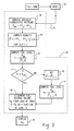
- FIG. 3 is a flow diagram of the algorithm of the controller of the system of FIG. 2.
-
- Referring to FIG. 1, the system is shown as implemented in a typical
vehicle fuel tank 10 having a filler tube or neck 12 and filled with volatile liquid fuel to a depth denoted by reference character "h". A lower solid state pressure sensor PT2 is disposed closely adjacent the bottom of the tank with a second sensor PT1 supported on a bracket 14 a unit distance Δh above sensor PT2. In the present practice of the invention for liquid level measurements in inches, density in pounds per cubic inch, Δh is set at one inch. A third sensor PT3 is disposed on the underside of the upper wall of the fuel tank at its highest point for sensing vapor pressure above the liquid level of the fuel. - Referring to FIG. 2, an electrical schematic of the system of the present invention is indicated generally at 16 and includes a
controller 18 having embedded therein amicroprocessor 20 and thecontroller 18 is connected alongline 22 to thevehicle power supply 24. - Pressure sensor PT1 is connected to the
controller 18 alongline 26; sensor PT2 connected tocontroller 18 alongline 28; and, sensor PT3 connected to thecontroller 18 alongline 30. It will be understood that the electrical leads within thetank 10 corresponding to thelines line 32 to aremote display 34 which in the application to a motor vehicle would comprise the fuel level indicator on the operator's instrument panel. - Referring to FIG. 3, the operating program of the
controller 18 is illustrated where, upon receiving a reset signal alongline 36, the computer withincontroller 18 computes atstep 38 the apparent hydrostatic pressure PAH from the difference in the signals from PT2 and PT3. The system then proceeds tostep 40 to compute the density by normalizing for the vertical distance therebetween the pressure readings of sensors PT1 and PT2 disposed in the liquid. The system then proceeds tostep 42 and computes the fuel level h using the density ρt computed fromstep 40 and the apparent hydrostatic pressure PAH computed atstep 38. - The system then proceeds to
step 44 and inquires as to whether the fuel level h is equal to or greater than the height of PT1; and, if the liquid level is below PT1, i.e., the determination atstep 44 is negative, the system proceeds tostep 46 uses the density previously calculated and proceeds tostep 47. Atstep 47, the fuel level is again computed and the system proceeds tostep 48. If, however, the determination ofstep 44 is affirmative that the fuel level is above PT1, the system proceeds tostep 48 and determines the fuel reserve volume VR from a lookup table of values of VR as a function of values of fuel level h for the known tank configuration. - Upon refueling and filling the tank, the system is reset at
step 50 which may comprise a manual reset by the vehicle operator. - The present invention thus provides for an accurate indication of the volume of reserve fuel in a tank computed from signal outputs from solid state sensors disposed in the tank. A pair of sensors located near the bottom of the tank and vertically spaced a predetermined increment provide outputs from which the fuel density may be computed. The difference between the lower sensor reading in the bottom of the tank and a third sensor disposed at the highest point in the tank for sensing vapor pressure above the liquid provides a basis for computing the apparent hydrostatic pressure in the tank which is then employed for computing the actual liquid level from the previously computed density. The reserve volume of fuel is then obtained from a lookup table of tank volume at varied levels of liquid fuel in the tank. The present invention thus provides a relatively low cost and reliable alternative to a mechanical float type level sensor heretofore widely employed in fuel tanks for motor vehicles.
- Although the invention has hereinabove been described with respect to the illustrated embodiments, it will be understood that the invention is capable of modification and variation and is limited only by the following claims.
Claims (9)
- A liquid volume monitoring system for a motor vehicle fuel tank comprising:(a) a first pressure sensor disposed on the upper wall of the fuel tank for sensing fuel vapor dome pressure;(b) a second pressure sensor disposed on the bottom of the tank for sensing the hydrostatic pressure of the liquid in the tank;(c) a third pressure sensor disposed a certain distance above said second sensor for sensing hydrostatic pressure at said certain distance;(d) signal processing circuitry including a computer operatively connected to said sensors and receiving output signals therefrom, said circuitry operative to subtract the output of said first sensor from the output of said second sensor to determine apparent hydrostatic pressure of the liquid in said tank; and, said circuitry operative to compare the output of the third sensor with the output of said second sensor and to compute the density of said liquid;(e) said computer further operative to compute the actual level of liquid in said tank from a look-up table of values of density as a function of determined apparent hydrostatic pressure at a given distance; wherein said computer is operative to (i) compute the volume of liquid in said tank from said level signal and known tank dimensions stored in said computer; and, (ii) output a signal indicative of said computed volume.
- The system defined in claim 1 wherein said pressure sensors comprise solid state transducers.
- The system defined in claim 1 wherein said third sensor is disposed about one inch (25.4 mm) above said second sensor.
- A method of monitoring the amount of liquid in a vehicle fuel tank comprising:(a) disposing a first pressure sensor at the top of the tank and sensing fuel vapor pressure and generating a first sensor signal indicative of the sensed pressure;(b) disposing a second pressure sensor at the bottom of the tank and sensing the hydrostatic pressure of the liquid in the tank and generating a second sensor signal indicative of the sensed pressure;(c) disposing a third pressure sensor in said tank and sensing the hydrostatic pressure of the liquid at a certain distance above said second sensor and generating a third sensor signal indicative of the sensed pressure at said certain distance;(d) providing signal processing circuitry including a computer on the vehicle and connecting said circuitry to receive said first, second and third sensor signals;(e) subtracting said first sensor signal from said second sensor signal and computing the apparent hydrostatic pressure of the liquid in said tank;(f) comparing said second and third sensor signals and computing the density of the liquid in the tank based on said certain distance;(g) determining the actual liquid level in the tank at the computed density and apparent hydrostatic pressure from a look-up table of values of liquid level as a function of density and apparent hydrostatic pressure;(h) generating an output level signal indicative of said actual fluid level;(i) computing actual liquid volume from said level signal and known tank dimensions stored in said computer.
- The method defined in claim 4, wherein said step of disposing first, second and third sensors includes disposing solid state transducers.
- The method defined in claim 4, wherein said step of disposing said third sensor comprises disposing said third sensor about one inch (25.4 mm) above said second sensor.
- The method defined in claim 4, further comprising generating a fuel reserve signal indicative of said computed volume and displaying said computed volume to the vehicle operator as the fuel reserve.
- The method defined in claim 4, wherein said step of comparing said second and third signals includes disabling said comparing when the fuel level is below said certain distance.
- The method defined in claim 4, wherein said step of comparing said second and third signals includes disabling said comparing when said fuel level is below said certain distance and said step of computing includes storing the last computed value until the tank is filled and the fuel level raised above said certain distance.
Applications Claiming Priority (2)
| Application Number | Priority Date | Filing Date | Title |
|---|---|---|---|
| US09/570,840 US6282953B1 (en) | 2000-05-12 | 2000-05-12 | Solid state fuel level sensing |
| US570840 | 2000-05-12 |
Publications (3)
| Publication Number | Publication Date |
|---|---|
| EP1153784A2 true EP1153784A2 (en) | 2001-11-14 |
| EP1153784A3 EP1153784A3 (en) | 2004-01-02 |
| EP1153784B1 EP1153784B1 (en) | 2006-03-29 |
Family
ID=24281261
Family Applications (1)
| Application Number | Title | Priority Date | Filing Date |
|---|---|---|---|
| EP01110949A Expired - Lifetime EP1153784B1 (en) | 2000-05-12 | 2001-05-07 | Solid state fuel level sensing |
Country Status (10)
| Country | Link |
|---|---|
| US (1) | US6282953B1 (en) |
| EP (1) | EP1153784B1 (en) |
| JP (1) | JP2002013962A (en) |
| KR (1) | KR100861518B1 (en) |
| AT (1) | ATE321679T1 (en) |
| BR (1) | BR0102555A (en) |
| CA (1) | CA2346737A1 (en) |
| DE (1) | DE60118272T2 (en) |
| MX (1) | MXPA01004807A (en) |
| TW (1) | TW548207B (en) |
Cited By (5)
| Publication number | Priority date | Publication date | Assignee | Title |
|---|---|---|---|---|
| EP1582848A1 (en) * | 2004-04-02 | 2005-10-05 | Hectronic Ag | Method and apparatus for testing the type and the quality of a liquid in a tank |
| DE102013109128A1 (en) * | 2013-08-23 | 2015-02-26 | Endress + Hauser Gmbh + Co. Kg | Hydrostatic boundary layer measuring device |
| WO2015074163A1 (en) * | 2013-11-22 | 2015-05-28 | Hidalgo Balboa Erving Javier | Mobile or replaceable liquid fuel tank system for trucks, for example such as the large trucks used in the mining industry |
| US20230009318A1 (en) * | 2021-07-09 | 2023-01-12 | Vega Grieshaber Kg | Measuring Method and Measuring Assembly |
| EP3330681B1 (en) * | 2016-12-02 | 2023-07-05 | Simmonds Precision Products, Inc. | Determining fluid density within a tank |
Families Citing this family (49)
| Publication number | Priority date | Publication date | Assignee | Title |
|---|---|---|---|---|
| US6782339B2 (en) * | 2000-07-31 | 2004-08-24 | Chart Industries, Inc. | Differential pressure gauge for cryogenic fluids which selects a density value based on pressure measurement |
| USD497115S1 (en) | 2003-03-13 | 2004-10-12 | Gentach International Limited | Liquid level indicator for pressurized containers of volatile liquids |
| US6907780B1 (en) * | 2003-12-01 | 2005-06-21 | Motorola, Inc. | Fuel level sensor |
| US7032449B2 (en) * | 2004-07-14 | 2006-04-25 | Intevep, S.A. | Measurement of fluid properties in vessel and sensor for same |
| US7706671B2 (en) | 2005-03-16 | 2010-04-27 | B2M Asset Management, Llc | Multi-function liquid container |
| US8813551B2 (en) * | 2005-04-10 | 2014-08-26 | Future Path Medical Holding Co. Llc | Device that accurately measures physiological fluid flow |
| DE102005058298A1 (en) * | 2005-12-07 | 2007-06-21 | Robert Bosch Gmbh | Method and device for detecting tank leaks |
| CN200950091Y (en) * | 2006-10-10 | 2007-09-19 | 中国国际海运集装箱(集团)股份有限公司 | Pressure and Level Sensors for Tank Containers and Tank Trucks |
| EP2086846A4 (en) * | 2006-11-29 | 2012-01-25 | Future Path Medical Llc | Container for physiological fluids |
| JP2008222235A (en) * | 2007-03-08 | 2008-09-25 | Tatsuno Corp | Oil quantity measurement system |
| JP5066456B2 (en) * | 2008-02-05 | 2012-11-07 | 株式会社小松製作所 | Fuel amount detection device |
| JP5232488B2 (en) * | 2008-02-05 | 2013-07-10 | 株式会社小松製作所 | Fuel quality judgment device |
| JP5550817B2 (en) * | 2008-04-18 | 2014-07-16 | 横河電機株式会社 | Level measuring apparatus, level measuring system, level measuring method, computer program, and computer-readable recording medium |
| DE102009049676A1 (en) * | 2009-10-12 | 2011-04-14 | Digades Gmbh Digitales Und Analoges Schaltungsdesign | Device and method for level measurement in arbitrarily shaped containers, in particular within motor vehicle tanks |
| US8984934B2 (en) * | 2013-03-13 | 2015-03-24 | Ford Global Technologies, Llc | Method and system to validate a fuel level indicator in a vehicle |
| US9377341B1 (en) * | 2013-04-12 | 2016-06-28 | Joe David Watson | Electronic liquid level sensing device and gauge for liquid-immersed power transformers, reactors and similar equipment |
| US20140305201A1 (en) * | 2013-04-12 | 2014-10-16 | Joe David Watson | Electronic liquid level sensing device and gauge for liquid-immersed power transformers, reactors and similar equipment |
| US12094269B2 (en) | 2013-10-30 | 2024-09-17 | S1 Technologies, Inc. | System and method for identifying a fuel loss event |
| US9557207B2 (en) * | 2013-10-30 | 2017-01-31 | S1 Technologies, Inc. | System and method for determining volume of fluid in a tank |
| US11100456B2 (en) | 2013-10-30 | 2021-08-24 | S1 Technologies, Inc. | System and method for determining volume of fluid in a tank |
| US11085805B2 (en) | 2013-10-30 | 2021-08-10 | S1 Technologies, Inc. | System and method for identifying a fuel loss |
| US9546894B2 (en) | 2014-03-26 | 2017-01-17 | Ford Global Technologies, Llc | System and methods for fuel level inference |
| US9770979B2 (en) | 2014-05-19 | 2017-09-26 | Ford Global Technologies, Llc | Object positioning method |
| EP2962887A1 (en) * | 2014-07-02 | 2016-01-06 | Inergy Automotive Systems Research (Société Anonyme) | Method for controlling a filling operation of a vehicular liquid storage system |
| CN103983323B (en) * | 2014-06-06 | 2017-12-22 | 国家电网公司 | Hydropower station water level measuring method and hydropower station water level monitoring system |
| CN104089680B (en) * | 2014-07-25 | 2018-01-12 | 赵云华 | The measuring method and device of liquid level height |
| US9770980B2 (en) | 2014-09-18 | 2017-09-26 | Ford Global Technologies, Llc | System and methods for determining fuel fill level and diagnosing fill level indicator |
| US10571074B2 (en) * | 2014-10-28 | 2020-02-25 | Sikorsky Aricraft Corporation | Lubricant level sensing for an actuator |
| GB2556775B (en) | 2015-09-16 | 2019-10-09 | Halliburton Energy Services Inc | Method and apparatus for measuring characteristics of fluid in a reservoir |
| CN108431556A (en) * | 2015-09-28 | 2018-08-21 | 伊顿智能动力有限公司 | Solid State Fuel Level Sensor |
| US10759649B2 (en) * | 2016-04-22 | 2020-09-01 | American Energy Innovations, Llc | System and method for automatic fueling of hydraulic fracturing and other oilfield equipment |
| US10882732B2 (en) | 2016-04-22 | 2021-01-05 | American Energy Innovations, Llc | System and method for automatic fueling of hydraulic fracturing and other oilfield equipment |
| US10126158B2 (en) * | 2016-08-22 | 2018-11-13 | The Boeing Company | Systems and methods for determining a fuel level measurement of a fuel tank using optical sensor |
| GB201705039D0 (en) | 2017-03-29 | 2017-05-10 | Weston Aerospace Ltd | A Liquid level monitoring system |
| JP6794899B2 (en) * | 2017-03-30 | 2020-12-02 | 富士通株式会社 | Liquid level measurement system, liquid level measurement method, and liquid level measurement program |
| JP6873795B2 (en) * | 2017-04-06 | 2021-05-19 | 株式会社Ihiプラント | Liquefied gas receiving device |
| MX2019012855A (en) * | 2017-04-28 | 2021-01-08 | Gregory E Young | Precision depth sensor. |
| WO2019051145A1 (en) * | 2017-09-07 | 2019-03-14 | Graco Minnesota Inc. | Tank volume monitoring using sensed fluid pressure |
| US10954115B2 (en) * | 2017-12-18 | 2021-03-23 | Maxum Enterprises, Llc | System and method for delivering fuel |
| GB2575690A (en) | 2018-07-20 | 2020-01-22 | Gillespie Avionics Ltd | Liquid measurement device for a tank |
| EP3861300B1 (en) * | 2018-10-01 | 2023-02-22 | Johnson Matthey Public Limited Company | An apparatus for determining a vertical level or density profile of a fluid column |
| CN111192448B (en) * | 2019-12-23 | 2021-01-12 | 浙江中控技术股份有限公司 | Remote transmission liquid level transmitter system based on HART communication and use method thereof |
| CN111060178A (en) * | 2019-12-31 | 2020-04-24 | 江苏远望仪器科技有限公司 | Method for acquiring liquid level in cabin |
| CN112304805A (en) * | 2020-11-27 | 2021-02-02 | 大连海事大学 | Slurry density measuring device and density measuring method |
| CN113212155A (en) * | 2021-06-29 | 2021-08-06 | 山河智能装备股份有限公司 | Oil suction opening structure of fuel tank and fuel tank |
| JP7482089B2 (en) * | 2021-08-20 | 2024-05-13 | 株式会社小松製作所 | Construction Machinery |
| CN115371763A (en) * | 2022-08-08 | 2022-11-22 | 重庆远达烟气治理特许经营有限公司科技分公司 | Tower body liquid level measuring system |
| US20240310261A1 (en) * | 2023-03-14 | 2024-09-19 | Saudi Arabian Oil Company | Automated system for fluid quality inside the impulse line differential pressure transmitter for interface level measurement and method of use |
| DE102024107398A1 (en) * | 2024-03-15 | 2025-09-18 | Vega Grieshaber Kg | METHOD FOR CONFIGURING A LEVEL SENSOR |
Family Cites Families (11)
| Publication number | Priority date | Publication date | Assignee | Title |
|---|---|---|---|---|
| US4043193A (en) * | 1976-08-03 | 1977-08-23 | Bailey Mud Monitors Inc. | Method and apparatus for measuring volume and density of fluids in a drilling fluid system |
| JPS5622917A (en) * | 1979-08-02 | 1981-03-04 | Taeko Uchiki | Liquid level indicator |
| JPS5833126A (en) * | 1981-08-24 | 1983-02-26 | Toshiba Corp | Liquid level detector |
| US4625553A (en) * | 1985-04-12 | 1986-12-02 | Dresser Industries, Inc. | System to determine the level and weight of liquid in a tank or the like |
| US4949572A (en) * | 1988-11-30 | 1990-08-21 | Computer Instruments Corporation | Method and apparatus for determining physical properties of liquids |
| IL93545A (en) * | 1990-02-27 | 1992-12-01 | Uri Zfira | Liquid counter |
| GB9011084D0 (en) * | 1990-05-17 | 1990-07-04 | Ag Patents Ltd | Volume measurement |
| US5261276A (en) * | 1992-05-04 | 1993-11-16 | Henry Gifford | Fuel oil monitor system and method |
| US5351725A (en) * | 1993-04-01 | 1994-10-04 | Optimum Applied Systems, Inc. | System for monitoring fills of liquid in a tank container and ongoing liquid condition |
| US5604315A (en) * | 1995-01-12 | 1997-02-18 | Setra Systems, Inc. | Apparatus using a feedback network to measure fluid pressures |
| US5900547A (en) * | 1997-09-12 | 1999-05-04 | Thermoprobe Inc. | Differential level hydrometer |
-
2000
- 2000-05-12 US US09/570,840 patent/US6282953B1/en not_active Expired - Fee Related
-
2001
- 2001-05-07 AT AT01110949T patent/ATE321679T1/en not_active IP Right Cessation
- 2001-05-07 EP EP01110949A patent/EP1153784B1/en not_active Expired - Lifetime
- 2001-05-07 DE DE60118272T patent/DE60118272T2/en not_active Expired - Lifetime
- 2001-05-07 TW TW090110851A patent/TW548207B/en not_active IP Right Cessation
- 2001-05-08 CA CA002346737A patent/CA2346737A1/en not_active Abandoned
- 2001-05-10 JP JP2001140173A patent/JP2002013962A/en active Pending
- 2001-05-11 MX MXPA01004807A patent/MXPA01004807A/en active IP Right Grant
- 2001-05-11 KR KR1020010025773A patent/KR100861518B1/en not_active Expired - Fee Related
- 2001-05-11 BR BR0102555-4A patent/BR0102555A/en not_active IP Right Cessation
Non-Patent Citations (1)
| Title |
|---|
| None |
Cited By (5)
| Publication number | Priority date | Publication date | Assignee | Title |
|---|---|---|---|---|
| EP1582848A1 (en) * | 2004-04-02 | 2005-10-05 | Hectronic Ag | Method and apparatus for testing the type and the quality of a liquid in a tank |
| DE102013109128A1 (en) * | 2013-08-23 | 2015-02-26 | Endress + Hauser Gmbh + Co. Kg | Hydrostatic boundary layer measuring device |
| WO2015074163A1 (en) * | 2013-11-22 | 2015-05-28 | Hidalgo Balboa Erving Javier | Mobile or replaceable liquid fuel tank system for trucks, for example such as the large trucks used in the mining industry |
| EP3330681B1 (en) * | 2016-12-02 | 2023-07-05 | Simmonds Precision Products, Inc. | Determining fluid density within a tank |
| US20230009318A1 (en) * | 2021-07-09 | 2023-01-12 | Vega Grieshaber Kg | Measuring Method and Measuring Assembly |
Also Published As
| Publication number | Publication date |
|---|---|
| DE60118272D1 (en) | 2006-05-18 |
| TW548207B (en) | 2003-08-21 |
| EP1153784B1 (en) | 2006-03-29 |
| CA2346737A1 (en) | 2001-11-12 |
| MXPA01004807A (en) | 2004-11-10 |
| KR20010104273A (en) | 2001-11-24 |
| DE60118272T2 (en) | 2006-12-07 |
| BR0102555A (en) | 2003-02-25 |
| US6282953B1 (en) | 2001-09-04 |
| KR100861518B1 (en) | 2008-10-02 |
| EP1153784A3 (en) | 2004-01-02 |
| JP2002013962A (en) | 2002-01-18 |
| ATE321679T1 (en) | 2006-04-15 |
Similar Documents
| Publication | Publication Date | Title |
|---|---|---|
| US6282953B1 (en) | Solid state fuel level sensing | |
| US5105663A (en) | Apparatus and method for measuring low fuel level in a fuel tank | |
| CN102435261B (en) | For determining measurement mechanism and the method for the liquid level in fuel tank | |
| EP0275240B2 (en) | A method for determining and indicating the volume of fuel in the tank of a motor vehicle | |
| US5616838A (en) | Metering apparatus for cryogenic liquids | |
| US6252499B1 (en) | Fuel supply indicator arrangement for a motor vehicle fuel tank | |
| JP2003534527A (en) | Device for measuring and monitoring the volume of liquid in a container | |
| US20090272188A1 (en) | Binary Liquid Analyzer For Storage Tank | |
| KR100385541B1 (en) | Barometric pressure gauge | |
| JPH10193992A (en) | Method and apparatus for detecting remaining amount of fuel in fuel tank | |
| US4194396A (en) | Automobile fuel gauge system | |
| US6597998B1 (en) | Method for determining the amount of liquid in a reservoir as a function of depth of the liquid | |
| US5661228A (en) | Liquid pressure and level sensing instruments | |
| US20180216983A1 (en) | Solid state fuel level sensor | |
| KR101196083B1 (en) | System for measuring residual of liquid | |
| US20170370758A1 (en) | Fluid-level measuring sensor | |
| US3726140A (en) | Liquid level indicating means | |
| US7287556B2 (en) | Gas cap proximity mounted fuel indicator | |
| KR20010030255A (en) | Method and apparatus for detecting the level of fluid in a tank | |
| CN211504297U (en) | A glass cleaning fluid remaining amount measuring device and automobile | |
| JPH11325397A (en) | Remaining liquid amount measuring method for bulk supply | |
| KR20060054768A (en) | Vehicle fuel level measurement system and measurement method | |
| US20030010118A1 (en) | Apparatus for continuously measuring the liquid level in a container | |
| GB2273562A (en) | Fuel level indicator | |
| KR20220162355A (en) | Detecting device for residual fuel of fuel tank |
Legal Events
| Date | Code | Title | Description |
|---|---|---|---|
| PUAI | Public reference made under article 153(3) epc to a published international application that has entered the european phase |
Free format text: ORIGINAL CODE: 0009012 |
|
| AK | Designated contracting states |
Kind code of ref document: A2 Designated state(s): AT BE CH CY DE DK ES FI FR GB GR IE IT LI LU MC NL PT SE TR |
|
| AX | Request for extension of the european patent |
Free format text: AL;LT;LV;MK;RO;SI |
|
| PUAL | Search report despatched |
Free format text: ORIGINAL CODE: 0009013 |
|
| AK | Designated contracting states |
Kind code of ref document: A3 Designated state(s): AT BE CH CY DE DK ES FI FR GB GR IE IT LI LU MC NL PT SE TR |
|
| AX | Request for extension of the european patent |
Extension state: AL LT LV MK RO SI |
|
| RIC1 | Information provided on ipc code assigned before grant |
Ipc: 7G 01F 23/14 B Ipc: 7B 60K 15/077 A Ipc: 7B 60K 15/06 B |
|
| 17P | Request for examination filed |
Effective date: 20040403 |
|
| AKX | Designation fees paid |
Designated state(s): AT BE CH CY DE DK ES FI FR GB GR IE IT LI LU MC NL PT SE TR |
|
| 17Q | First examination report despatched |
Effective date: 20041102 |
|
| GRAP | Despatch of communication of intention to grant a patent |
Free format text: ORIGINAL CODE: EPIDOSNIGR1 |
|
| GRAS | Grant fee paid |
Free format text: ORIGINAL CODE: EPIDOSNIGR3 |
|
| GRAA | (expected) grant |
Free format text: ORIGINAL CODE: 0009210 |
|
| AK | Designated contracting states |
Kind code of ref document: B1 Designated state(s): AT BE CH CY DE DK ES FI FR GB GR IE IT LI LU MC NL PT SE TR |
|
| PG25 | Lapsed in a contracting state [announced via postgrant information from national office to epo] |
Ref country code: NL Free format text: LAPSE BECAUSE OF FAILURE TO SUBMIT A TRANSLATION OF THE DESCRIPTION OR TO PAY THE FEE WITHIN THE PRESCRIBED TIME-LIMIT Effective date: 20060329 Ref country code: CH Free format text: LAPSE BECAUSE OF FAILURE TO SUBMIT A TRANSLATION OF THE DESCRIPTION OR TO PAY THE FEE WITHIN THE PRESCRIBED TIME-LIMIT Effective date: 20060329 Ref country code: BE Free format text: LAPSE BECAUSE OF FAILURE TO SUBMIT A TRANSLATION OF THE DESCRIPTION OR TO PAY THE FEE WITHIN THE PRESCRIBED TIME-LIMIT Effective date: 20060329 Ref country code: AT Free format text: LAPSE BECAUSE OF FAILURE TO SUBMIT A TRANSLATION OF THE DESCRIPTION OR TO PAY THE FEE WITHIN THE PRESCRIBED TIME-LIMIT Effective date: 20060329 Ref country code: LI Free format text: LAPSE BECAUSE OF FAILURE TO SUBMIT A TRANSLATION OF THE DESCRIPTION OR TO PAY THE FEE WITHIN THE PRESCRIBED TIME-LIMIT Effective date: 20060329 |
|
| REG | Reference to a national code |
Ref country code: GB Ref legal event code: FG4D |
|
| REG | Reference to a national code |
Ref country code: CH Ref legal event code: EP |
|
| REG | Reference to a national code |
Ref country code: IE Ref legal event code: FG4D |
|
| PG25 | Lapsed in a contracting state [announced via postgrant information from national office to epo] |
Ref country code: IE Free format text: LAPSE BECAUSE OF NON-PAYMENT OF DUE FEES Effective date: 20060508 |
|
| REF | Corresponds to: |
Ref document number: 60118272 Country of ref document: DE Date of ref document: 20060518 Kind code of ref document: P |
|
| PGFP | Annual fee paid to national office [announced via postgrant information from national office to epo] |
Ref country code: FR Payment date: 20060519 Year of fee payment: 6 Ref country code: GB Payment date: 20060519 Year of fee payment: 6 |
|
| PGFP | Annual fee paid to national office [announced via postgrant information from national office to epo] |
Ref country code: SE Payment date: 20060522 Year of fee payment: 6 |
|
| REG | Reference to a national code |
Ref country code: SE Ref legal event code: TRGR |
|
| PG25 | Lapsed in a contracting state [announced via postgrant information from national office to epo] |
Ref country code: MC Free format text: LAPSE BECAUSE OF NON-PAYMENT OF DUE FEES Effective date: 20060531 |
|
| PGFP | Annual fee paid to national office [announced via postgrant information from national office to epo] |
Ref country code: IT Payment date: 20060531 Year of fee payment: 6 |
|
| PG25 | Lapsed in a contracting state [announced via postgrant information from national office to epo] |
Ref country code: DK Free format text: LAPSE BECAUSE OF FAILURE TO SUBMIT A TRANSLATION OF THE DESCRIPTION OR TO PAY THE FEE WITHIN THE PRESCRIBED TIME-LIMIT Effective date: 20060629 |
|
| PG25 | Lapsed in a contracting state [announced via postgrant information from national office to epo] |
Ref country code: ES Free format text: LAPSE BECAUSE OF FAILURE TO SUBMIT A TRANSLATION OF THE DESCRIPTION OR TO PAY THE FEE WITHIN THE PRESCRIBED TIME-LIMIT Effective date: 20060710 |
|
| PG25 | Lapsed in a contracting state [announced via postgrant information from national office to epo] |
Ref country code: PT Free format text: LAPSE BECAUSE OF FAILURE TO SUBMIT A TRANSLATION OF THE DESCRIPTION OR TO PAY THE FEE WITHIN THE PRESCRIBED TIME-LIMIT Effective date: 20060829 |
|
| REG | Reference to a national code |
Ref country code: CH Ref legal event code: PL |
|
| NLV1 | Nl: lapsed or annulled due to failure to fulfill the requirements of art. 29p and 29m of the patents act | ||
| ET | Fr: translation filed | ||
| PLBE | No opposition filed within time limit |
Free format text: ORIGINAL CODE: 0009261 |
|
| STAA | Information on the status of an ep patent application or granted ep patent |
Free format text: STATUS: NO OPPOSITION FILED WITHIN TIME LIMIT |
|
| 26N | No opposition filed |
Effective date: 20070102 |
|
| EUG | Se: european patent has lapsed | ||
| GBPC | Gb: european patent ceased through non-payment of renewal fee |
Effective date: 20070507 |
|
| REG | Reference to a national code |
Ref country code: FR Ref legal event code: ST Effective date: 20080131 |
|
| PG25 | Lapsed in a contracting state [announced via postgrant information from national office to epo] |
Ref country code: GR Free format text: LAPSE BECAUSE OF FAILURE TO SUBMIT A TRANSLATION OF THE DESCRIPTION OR TO PAY THE FEE WITHIN THE PRESCRIBED TIME-LIMIT Effective date: 20060630 |
|
| PG25 | Lapsed in a contracting state [announced via postgrant information from national office to epo] |
Ref country code: GB Free format text: LAPSE BECAUSE OF NON-PAYMENT OF DUE FEES Effective date: 20070507 |
|
| PG25 | Lapsed in a contracting state [announced via postgrant information from national office to epo] |
Ref country code: FI Free format text: LAPSE BECAUSE OF FAILURE TO SUBMIT A TRANSLATION OF THE DESCRIPTION OR TO PAY THE FEE WITHIN THE PRESCRIBED TIME-LIMIT Effective date: 20060329 Ref country code: SE Free format text: LAPSE BECAUSE OF NON-PAYMENT OF DUE FEES Effective date: 20070508 |
|
| PG25 | Lapsed in a contracting state [announced via postgrant information from national office to epo] |
Ref country code: FR Free format text: LAPSE BECAUSE OF NON-PAYMENT OF DUE FEES Effective date: 20070531 Ref country code: LU Free format text: LAPSE BECAUSE OF NON-PAYMENT OF DUE FEES Effective date: 20060507 Ref country code: TR Free format text: LAPSE BECAUSE OF FAILURE TO SUBMIT A TRANSLATION OF THE DESCRIPTION OR TO PAY THE FEE WITHIN THE PRESCRIBED TIME-LIMIT Effective date: 20060329 |
|
| PG25 | Lapsed in a contracting state [announced via postgrant information from national office to epo] |
Ref country code: CY Free format text: LAPSE BECAUSE OF FAILURE TO SUBMIT A TRANSLATION OF THE DESCRIPTION OR TO PAY THE FEE WITHIN THE PRESCRIBED TIME-LIMIT Effective date: 20060329 |
|
| PG25 | Lapsed in a contracting state [announced via postgrant information from national office to epo] |
Ref country code: IT Free format text: LAPSE BECAUSE OF NON-PAYMENT OF DUE FEES Effective date: 20070507 |
|
| PGFP | Annual fee paid to national office [announced via postgrant information from national office to epo] |
Ref country code: DE Payment date: 20110531 Year of fee payment: 11 |
|
| REG | Reference to a national code |
Ref country code: DE Ref legal event code: R119 Ref document number: 60118272 Country of ref document: DE Effective date: 20121201 |
|
| PG25 | Lapsed in a contracting state [announced via postgrant information from national office to epo] |
Ref country code: DE Free format text: LAPSE BECAUSE OF NON-PAYMENT OF DUE FEES Effective date: 20121201 |