BACKGROUND OF THE INVENTION
1. Field of the Invention
-
The present invention relates to a brazing
method of a brazement comprising interposing a nickel-based
brazing filler metal layer between brazing parts of
first and second joining members or first and second
shaped plates comprised of stainless steel and heating
them in that state to a temperature of at least the
melting point of the nickel-based brazing filler metal
layer to braze together the first and second joining
members, more particularly relates to a method for
production of a corrosion resistant heat exchanger
produced by brazing and having brazing parts of first and
second joining members or first and second shaped plates
exposed to a corrosive environment through which a
corrosive fluid flows, and a brazement and corrosion
resistant heat exchanger obtained by these methods
2. Description of the Related Art
-
In the past, an exhaust gas heat exchanger for
cooling exhaust gas recirculation gas (EGR gas) of an
exhaust gas recycling system which takes out part of the
exhaust gas from an engine exhaust system and returns it
to the intake system for addition to the air-fuel mixture
has been exposed to high temperature (more than 400°C or
so) EGR gas containing sulfides and condensed water from
the same, so generally has been required to have a high
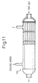
corrosion resistance. Therefore, exhaust gas heat
exchangers have generally been of the multipipe corrosion
resistant heat exchanger type using superior corrosion
and heat resistant stainless steel (see FIG. 11) as shown
in Japanese Unexamined Patent Publication (Kokai) No. 9-310995
and Japanese Design Registration No. 1021832.
-
To join such stainless steel, considering the
need for heat resistance and corrosion resistance, use is
made of the nickel brazing filler metals stipulated in
industrial standards such as the Japan Industrial
Standard (JIS) and improved versions. Such nickel brazing
filler metals are extremely expensive compared with
general copper brazing filler metals etc. Nickel brazing
filler metals are available in a powder, paste, or foil
form. Powder or paste materials are coated on the
required locations, while foil materials are preplaced.
Nickel brazing filler metal foil is particularly
expensive among the nickel brazing filler metals, so
generally a paste is used. In the case of the multipipe
corrosion resistant heat exchanger 100, the brazing
filler metal for joining the parts has to be applied to
about six locations. The area of coating, that is, the
amount used, is small, so even if an expensive brazing
filler metal is used, it does not lead to a large rise in
cost. To reduce the size and improve performance,
however, corrosion resistant heat exchangers of a stacked
plate structure comprised of a plurality of first and
second shaped plates made of stainless steel superior in
corrosion resistance stacked and brazed together to form
fluid channels for EGR gas between them are being
researched and developed as corrosion resistant heat
exchangers enabling an increase in heat exchange area
between the EGR gas and cooling water.
-
In such a stacked plate structure corrosion
resistant heat exchanger, however, if trying to interpose
a paste of a nickel brazing filler metal between the
brazing parts of the first and second shaped plates, the
number of coating steps and the amount of nickel brazing
filler metal used would become tremendous due to the
extremely large number of locations where the paste of
the nickel brazing filler metal has to be applied. This
creates the problem of a large rise in cost. Further, in
the case of a nickel brazing filler metal foil, in
addition to the preplaced brazing step, the nickel
brazing filler metal foil itself is extremely expensive,
so there is the problem that the cost rises even more
than with a paste of the nickel brazing filler metal. In
this way, if using a brazing method using a conventional
brazing filler metal, the cost ends up rising to a level
not suitable for the final product.
-
Therefore, Japanese Unexamined Patent
Publication (Kokai) No. 11-148791 discloses a stacked
plate type heat exchanger comprised of a plurality of
first and second channel plates with plated layers on
their two sides. The channels and through holes are made
in the first and second channel plates of this stacked
plate type heat exchanger by press forming, then the
surfaces are plated with the appropriate brazing filler
metal. For example, when the plates are made of stainless
steel, use is made of platings mainly comprised of nickel
and phosphorus. Therefore, note was taken of the
composition of Ni89-P11 stipulated for JIS Bni6. This
brazing filler metal is supplied in a paste form, but can
also be plated on stainless steel. By heating such a
plated stainless steel, the plating can be made to
function as a brazing filler metal. There was however,
first, a problem that a nickel-phosphorus-based brazing
filler metal is somewhat inferior in corrosion resistance
to chrome-containing nickel-based brazing filler metals.
Further, second, there was a problem that cracks
sometimes occurred in the brazing filler metal layer due
to the brazing conditions (heating temperature and time
and cooling time).
-
The first problem of the inferior corrosion
resistance is due to the fact that chrome itself has a
high corrosion resistance. The second problem of the
cracking is due to the fact that the molten brazing
filler metal shrinks when cooled. Inside the brazing
filler metal is formed a metal structure comprising
nickel, phosphorus, iron (diffused from the stainless
steel), etc. Cracks occur at the grain boundaries of the
metal structure of the brazing filler metal. Therefore,
to prevent cracking, it is desirable to make the metal
structure finer. The inventors therefore considered
plating a nickel-phosphorus-chrome alloy on a plate at a
single plating operation. There are two plating methods
for this: electroless plating and electroplating. It has
been generally believed that in electroless plating,
chrome ions inhibit the precipitation reaction of nickel
ions, so it is difficult to plate both nickel and chrome.
Further, in electroplating, it is said that chrome
plating is difficult with chrome ions and nickel ions
since nickel ions have 20 times or more better
precipitation ability.
SUMMARY OF THE INVENTION
-
An object of the present invention is to provide an
inexpensive brazing method of a brazement whereby first
and second joining members are brazed together without
use of an expensive paste of a nickel brazing filler
metal or nickel brazing filler metal foil and a brazement
obtained by the same. Another object of the present
invention is to provide a method of production of an
inexpensive corrosion resistant heat exchanger whereby
fluid channels and inner fins or first and second shaped
plates are brazed together without use of an expensive
paste of nickel brazing filler metal or nickel brazing
filler metal foil and a corrosion resistant heat
exchanger obtained by the same.
-
According to a first aspect of the present
invention, there is provided a brazing method for a
brazement comprised of first and second joining members
comprised of stainless steel brazed together and having
brazing parts of the first and second joining members
exposed to a corrosive environment in which a corrosive
fluid flows, comprising a first step of plating chrome on
a brazing part of at least one of the first and second
joining members to form a chrome-based brazing filler
metal layer at the brazing part of that at least one
joining member, a second step of plating nickel-phosphorus
on the chrome-based brazing filler metal layer
to form a nickel-based brazing filler metal layer on the
chrome-based brazing filler metal layer, and a third step
of heating to a temperature of at least the melting point
of the nickel-based brazing filler metal layer to braze
together the first and second joining members in the
state with the chrome-based brazing filler metal layer
and the nickel-based brazing filler metal layer
interposed between the brazing parts of the first and
second joining members.
-
According to a second aspect of the present
invention, there is provided a brazing method for a
brazement comprised of first and second joining members
comprised of stainless steel brazed together and having
brazing parts of the first and second joining members
exposed to a corrosive environment in which a corrosive
fluid flows, comprising a first step of plating chrome on
a brazing part of at least one of the first and second
joining members to form a chrome-based brazing filler
metal layer at the brazing part of that at least one
joining member, a second step of plating nickel-phosphorus
on the chrome-based brazing filler metal layer
to form a nickel-based brazing filler metal layer on the
chrome-based brazing filler metal layer, a third step of
plating copper on the nickel-based brazing filler metal
layer to form a copper-based brazing filler metal layer
on the nickel-based brazing filler metal layer, and a
fourth step of heating to a temperature of at least the
melting point of the nickel-based brazing filler metal
layer to braze together the first and second joining
members in the state with the chrome-based brazing filler
metal layer, the nickel-based brazing filler metal layer,
and the copper-based brazing filler metal layer
interposed between the brazing parts of the first and
second joining members.
-
Preferably, in the first and second aspects of the
invention, at least one of the joining members of the
first and second joining members is at least one of a
housing through which a heat exchange medium flows and
comprised of stainless steel, a fluid channel arranged
inside the housing and comprised of stainless steel, an
inner fin arranged inside the fluid channel and comprised
of stainless steel, a core plate connected to one end of
a fluid channel and comprised of stainless steel, and a
tank plate forming a tank chamber with the core plate and
comprised of stainless steel.
-
According to a third aspect of the present
invention, there is provided a brazement comprised of
first and second joining members comprised of stainless
steel brazed together and having brazing parts of the
first and second joining members exposed to a corrosive
environment in which a corrosive fluid flows, wherein a
brazing filler metal layer containing nickel, chrome, and
phosphorus is interposed between the first joining member
and the second joining member.
-
Preferably, the brazing filler metal layer further
includes copper.
-
According to a fourth aspect of the present
invention, there is provided a method of production of a
corrosion-resistant heat exchanger comprised of a housing
comprised of stainless steel, a fluid channel arranged in
the housing and comprised of stainless steel, and an
inner fin arranged inside the fluid channels and
comprised of stainless steel, a first joining member
comprised of said housing or said fluid channel and a
second joining member comprised of said fluid channel or
said inner fin being brazed together and having brazing
parts of the first and second shaped plates exposed to a
corrosive environment in which a corrosive fluid flows,
comprising a first step of plating chrome on a brazing
part of at least one of the first and second joining
members to form a chrome-based brazing filler metal layer
at the brazing part of that at least one joining member,
a second step of plating nickel-phosphorus on the chrome-based
brazing filler metal layer to form a nickel-based
brazing filler metal layer on the chrome-based brazing
filler metal layer, and a third step of heating to a
temperature of at least the melting point of the nickel-based
brazing filler metal layer to braze together the
first and second joining members in the state with the
chrome-based brazing filler metal layer and the nickel-based
brazing filler metal layer interposed between the
brazing parts of the first and second joining members.
-
According to a fifth aspect of the present
invention, there is provided a method of production of a
corrosion-resistant heat exchanger comprised of a housing
comprised of stainless steel, a fluid channel arranged in
the housing and comprised of stainless steel, and an
inner fin arranged inside the fluid channel and comprised
of stainless steel, a first joining member comprised of
said housing or said fluid channel and a second joining
member comprised of said fluid channel or said inner fin
being brazed together and having brazing parts of the
first and second joining members exposed to a corrosive
environment in which a corrosive fluid flows, comprising
a first step of plating chrome on a brazing part of at
least one of the first and second joining members to form
a chrome-based brazing filler metal layer at the brazing
part of that at least one joining member, a second step
of plating nickel-phosphorus on the chrome-based brazing
filler metal layer to form a nickel-based brazing filler
metal layer on the chrome-based brazing filler metal
layer, a third step of plating copper on the nickel-based
brazing filler metal layer to form a copper-based brazing
filler metal layer on the nickel-based brazing filler
metal layer, and a fourth step of heating to a
temperature of at least the melting point of the nickel-based
brazing filler metal layer to braze together the
first and second joining members in the state with the
chrome-based brazing filler metal layer, the nickel-based
brazing filler metal layer, and the copper-based brazing
filler metal layer interposed between the brazing parts
of the first and second joining members.
-
According to a sixth aspect of the present
invention, there is provided a method of production of a
corrosion-resistant heat exchanger comprised by a first
shaped plate of stainless steel and second shaped plate
of stainless steel stacked together and a fluid channel
provided between the first and second shaped plates and
forming a fluid path through which a corrosive fluid
flows, the first and second shaped plates being brazed
together and having brazing parts of the first and second
shaped plates exposed to a corrosive environment in which
a corrosive fluid flows, comprising a first step of
plating chrome on a brazing part of at least one of the
first and second shaped plates to form a chrome-based
brazing filler metal layer at the brazing part of that at
least one shaped plate, a second step of plating nickel-phosphorus
on the chrome-based brazing filler metal layer
to form a nickel-based brazing filler metal layer on the
chrome-based brazing filler metal layer, and a third step
of heating to a temperature of at least the melting point
of the nickel-based brazing filler metal layer to braze
together the first and second shaped plates in the state
with the chrome-based brazing filler metal layer and the
nickel-based brazing filler metal layer interposed
between the brazing parts of the first and second shaped
plates.
-
According to a seventh aspect of the present
invention, there is provided a method of production of a
corrosion-resistant heat exchanger comprised by a first
shaped plate of stainless steel and a second shaped plate
of stainless steel stacked together and a fluid channel
provided between the first and second shaped plates and
forming a fluid path through which a corrosive fluid
flows, the first and second shaped plates being brazed
together and having brazing parts of the first and second
shaped plates exposed to a corrosive environment in which
a corrosive fluid flows, comprising a first step of
plating chrome on a brazing part of at least one of the
first and second shaped plates to form a chrome-based
brazing filler metal layer at the brazing part of that at
least one shaped plate, a second step of plating nickel-phosphorus
on the chrome-based brazing filler metal layer
to form a nickel-based brazing filler metal layer on the
chrome-based brazing filler metal layer, a third step of
plating copper on the nickel-based brazing filler metal
layer to form a copper-based brazing filler metal layer
on the nickel-based brazing filler metal layer, and a
fourth step of heating to a temperature of at least the
melting point of the nickel-based brazing filler metal
layer to braze together the first and second shaped
plates in the state with the chrome-based brazing filler
metal layer, the nickel-based brazing filler metal layer,
and the copper-based brazing filler metal layer
interposed between the brazing parts of the first and
second shaped plates.
-
According to an eighth aspect of the present
invention, there is provided a corrosion resistant heat
exchanger comprised of a plurality of shaped plates made
of stainless steel superior in corrosion resistance
joined together in a thickness direction, provided
between each adjoining two shaped plates with a fluid
passage forming a fluid channel through which a corrosive
fluid flows, and having a plurality of said fluid
channels, wherein the plurality of shaped plates are
brazed together through a brazing filler metal layer
containing nickel, chrome, and phosphorus.
-
According to a ninth aspect of the present
invention, there is provided a corrosion resistant heat
exchanger comprised of a housing comprised of stainless
steel, a fluid channel arranged inside the housing,
carrying a corrosive fluid, and comprised of stainless
steel, and an inner fin arranged inside the fluid channel
and comprised of stainless steel, wherein the fluid
channel and the inner fin are brazed together through a
brazing filler metal layer containing nickel, chrome, and
phosphorus.
BRIEF DESCRIPTION OF THE DRAWINGS
-
These and other objects and features of the present
invention will be more apparent from the following
description given with reference to the accompanying
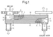
drawings, wherein: FIG. 1 is a sectional view of the
overall structure of a high corrosion resistance heat
exchanger of a stacked plate structure according to a
first embodiment of the present invention;
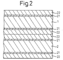
- FIG. 2 is a schematic view of joining parts of first
and second shaped plates with chrome plating or Ni-P
plating obtained by either electroless or electro plating
according to a first embodiment of the present invention;
- FIG. 3(a) is a schematic view of first and second
shaped plates given chrome plating and Ni-P plating
obtained by electroless or electro plating according to a
first embodiment of the present invention;
- FIG. 3(b) is a schematic view of first and second
shaped plates given an Ni-Cr-P alloy layer according to a
first embodiment of the present invention;
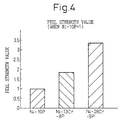
- FIG. 4 is a graph of the results of comparison of
the peeling strength of a brazing filler metal according
to the difference in amount of Ni according to a first
embodiment of the present invention;
- FIG. 5 is a graph of the results of comparison of
the fracture toughness of a brazing filler metal
according to the difference in amount of Ni according to
a first embodiment of the present invention;
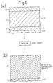
- FIG. 6(a) is a schematic view of first and second
shaped plates given chrome plating, Ni-P plating obtained
by electroless or electro plating, and Cu plating
according to a first embodiment of the present invention;
- FIG. 6(b) is a schematic view of first and second
shaped plates given an Ni-Cr-P-Cu alloy layer according
to a first embodiment of the present invention;
- FIG. 7 is a disassembled view of the main structure
of a multipipe high corrosion resistance heat exchange
according to a second embodiment of the present
invention;
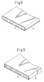
- FIG. 8 is a perspective view of an elliptically
shaped tube and inner fins according to a second
embodiment of the present invention;
- FIG. 9 is a perspective view of a rectangularly
shaped tube and inner fins according to a second
embodiment of the present invention;
- FIG. 10 is a perspective view of inner fins
according to a second embodiment of the present
invention;
- FIG. 11 is a sectional view of a multipipe corrosion
resistant heat exchanger according to the related art.
-
DESCRIPTION OF THE PREFERRED EMBODIMENTS
-
FIG. 1 to FIG. 6 are views of a first embodiment of
the present invention. FIG. 1 shows the overall structure
of a high corrosion resistance heat exchanger.
-
The high corrosion resistance heat exchanger of the
present embodiment is an EGR gas cooler for exchanging
heat between engine cooling water and EGR gas to cool the
EGR gas. This cooler is exposed to EGR gas of over 400°C
containing sulfides, nitric acid, sulfuric acid, ammonium
ions, acetic acid, etc. and water condensed from the
same, so is constructed by alternately stacking a
plurality of first and second shaped plates 1 and 2
comprised of highly corrosion resistant stainless steel
to form a stacked plate structure heat exchanger and
brazing it together.
-
The high corrosion resistance heat exchanger is
configured in the following way. That is, a plurality of
first and second shaped plates (corresponding to the
first and second joining members of the present
invention) 1 and 2 comprised of stainless steel processed
(pressed) into predetermined shapes are alternately
stacked in the plate thickness direction (vertical
direction in FIG. 1) to construct a stack 6 forming
exhaust passages through which the EGR gas from the
engine (not shown) may flow (corresponding to the fluid
passages of the present invention) and cooling water
passages 5 through which the engine cooling water may
flow. This stack is provided between end plates 16 and 17
arranged at a predetermined interval at the illustrated
upper and lower ends shown in FIG. 1.
-
Note that the exhaust passages 4 are formed in the
following way. In FIG. 1, first shaped plates having
upper end faces illustrated in FIG. 1 formed with concave
shapes (and with lower end faces illustrated formed with
convex shapes) and second shaped plates 2 with lower end
faces illustrated in FIG. 1 formed with concave shapes
(and with upper end faces formed with convex shapes) are
fit together in their thickness directions and are brazed
together in that state at least at the right ends
(joining parts) illustrated in FIG. 1 (in the present
example, the front ends illustrated in FIG. 1 and the
rear ends illustrated in FIG. 1 are also brazed together)
so as to form fluid channels (tubes) 3 inside them.
Inside the fluid channels are arranged inner fins 7
comprised of stainless steel for increasing the contact
area with the EGR gas and promoting the heat exchange
between the EGR gas and the cooling water. That is, the
exhaust passages 4 are formed between the first and
second shaped plates 1 and 2 in the vertical direction
illustrated in FIG. 1.
-
At the top of the high corrosion resistance heat
exchanger are connected a gas inlet pipe 10 forming an
inlet 9 for the EGR gas communicating with an inlet side
tank 8 communicating with a plurality of exhaust passages
4 and a gas outlet pipe 11 forming an outlet (not shown)
for the EGR gas finished with heat exchange communicating
with an outlet side tank (not shown) communicating with
the plurality of exhaust passages 4. The cooling water
passages 5 are formed inside the cooling water channels
(tubes) 18 obtained by stacking the second shaped plates
2 having upper end faces illustrated in FIG. 1 formed
with concave shapes and first shaped plates 1 with lower
end faces illustrated in FIG. 1 formed with concave
shapes in their thickness directions and brazing them in
that state at least at the left ends (joining parts)
illustrated in FIG. 1 (in the present example, the front
ends illustrated in FIG. 1 and the rear ends illustrated
in FIG. 1 are also brazed together). That is, the cooling
water channels 5 are formed between pairs of the second
and first shaped plates 2 and 1 adjoining each other in
the vertical direction illustrated in FIG. 1. Further, on
the top part of the high corrosion resistance heat
exchanger are connected a cooling water inlet pipe 14
formed with an inlet 13 for cooling water communicating
with an inlet side tank 12 communicating with a plurality
of cooling water passages 5 and a cooling water outlet
pipe 15 formed with an outlet (not shown) for cooling
water communicating with an outlet side tank (not shown)
communicating with the plurality of cooling water
passages 5.
Method of Production of First Embodiment
-
Next, the method of production of a high corrosion
resistance heat exchanger of the present embodiment will
be explained briefly based on FIG. 1 to FIG. 3. Here,
FIG. 2 is a schematic view of joining parts of first and
second shaped plates plated with chrome and Ni-P obtained
by electroless or electro plating.
-
Here, since there is generally a thin, tough oxide
coating on the surface of stainless steel, a plating with
a good adhesion is hard to obtain with just ordinary
pickling and activation. Further, the plating has to be
done quickly after removing the oxide coating. Therefore,
as pre-treatment for stainless steel, it is desirable to
preliminarily clean, rinse, electrolytically clean, then
rinse again the stainless steel. Here, as the stainless
steel, first and second shaped plates (base materials) 1
and 2 processed to give the shapes of the fluid channels
3 are used. The thicknesses of the first and second
shaped plates 1 and 2 are 0.2 to 0.4 mm or 1.2 to 1.6 mm.
Further, the materials of the first and second shaped
plates 1 and 2 are made chrome-containing ferrite (α-iron)
based stainless steel and nickel-chrome containing
austenite (γ iron) stainless steel.
-
Next, the two end faces of the first and second
shaped plates 1 and 2 are electroplated with chrome to 15
µm (Cr plating). The Cr plating is performed using 200 to
250 g/liter of chromic acid and a so-called Sargent
solution of 100 parts chromic acid and 1 part of sulfuric
acid at 45 to 55°C and 10 to 60 A/dm2. For example, the
first and second shaped plates 1 and 2 are immersed in a
plating bath through which a straight current (normal
current) is passed and held there for a suitable time.
The electrodeposition is started after the first and
second shaped plates 1 and 2 are warmed.
-
Alternatively, it is also possible to use as a
chrome plating bath a tetrachromate bath, a fluorine ion
added bath, a silicofluoric acid ion addition bath, a
crack free chrome plating bath, or a microcrack plating
bath. By chrome plating the two end faces of the first
and second shaped plates 1 and 2, as shown in FIG. 2, it
is possible to form a chrome-based brazing filler metal
layer (Cr) 21 mainly comprised of chrome on the two end
faces of the first and second shaped plates 1 and 2
(first step).
-
Next, the two end faces of the first and second
shaped plates 1 and 2 are given chemical nickel platings
(electroless Ni-P platings) to a thickness of 35 µm by
self-catalyzed plating reactions. Here, electroless Ni-P
(phosphorus) plating will be explained. Electroless Ni-P
plating is performed at a high temperature of 90 to 100°C
since a large plating thickness of several tens of
microns and high speed plating are desired. Normally,
this is used for treating an underlayer for soldering,
improving corrosion resistance, improving abrasion
resistance of sliding parts, and thickly plating tools
and other functional parts.
-
As this electroless Ni-P plating bath, use is made
of a phosphite bath containing a phosphite as a reducing
agent. By giving the two end faces of the first and
second shaped plates 1 and 2 electroless Ni-P platings in
this way, as shown in FIG. 2, a nickel-based brazing
filler metal layer (Ni-P) 22 of an Ni-P alloy containing
10% of phosphorus is formed on the two end faces of the
first and second shaped plates (second step).
-
Further, as shown in FIG. 2 and FIG. 3(a), the
joining parts of the first and second plates 1 and 2
formed with the chrome-based brazing filler metal layer
21 and the nickel-based brazing filler metal layer 22 on
their two end faces are stacked to form a fluid channel 3
with inner fins 7 inside the exhaust passage 4. A
plurality of fluid channels 3 of this structure are then
stacked to form a stack (stacked plate structure heat
exchanger) 6. The end plates 16 and 17 are overlaid at
the two ends of the stack 6 in the stacking direction,
the gas inlet pipe 10, gas outlet pipe 11, cooling water
inlet pipe 14, and cooling water outlet pipe 15 are
assembled at the predetermined locations of the end
plates 16 and 17 to form a stacked plate assembly.
-
Then the stacked plate assembly is brazed together
in a vacuum furnace or other heating furnace to produce a
high corrosion resistance heat exchanger made of
stainless steel. That is, by heating at a brazing
temperature higher than the melting point of the nickel-based
brazing filler metal layer 22 and lower than the
melting point of the chrome-based brazing filler metal
layer 21 (1000 to 1050°C) to melt the nickel-based
brazing filler metal in the state with the chrome-based
brazing filler metal layer 21 and the nickel-based
brazing filler metal layer 22 interposed between the
first and second shaping plates, the nickel-based brazing
filler metal flows by surface tension to the brazing
parts of the first and second shaped plates and brazes
the brazing parts of the first and second shaped plates.
Therefore, a high corrosion resistance heat exchanger
made of stainless steel is produced by brazing together a
stacked plate structure heat exchanger comprised of a
plurality of first and second shaped plates stacked in
the thickness direction (third step).
-
As a result, as shown in FIG. 3(b), by the melting
of the Ni, Cr, and P, a brazing filler metal containing
an alloy composition of Ni-Cr28-P8-etc. (nickel-chrome-phosphorus
alloy) 31 can be obtained. At this time, by
plating the two end faces of the first and second shaped
plates 1 and 2 with chrome before plating them with Ni-P,
it is possible to realize a finer metal structure in the
brazing filler metal 31, improve the strength of the
brazing filler metal and the fracture toughness, and
reduce the occurrence of cracks at the grain boundaries
in the metal structure. Note that as shown in FIG. 4, the
peeling strength of the brazing filler metal increases
along with an increase in the amount of Cr when Ni-10P is
made "1". As shown in FIG. 5, the fracture toughness of
the brazing filler metal also increases along with an
increase in the amount of chrome when Ni-10P is "1". Note
that by changing the brazing temperature when heating the
brazing filler metal to a temperature of its melting
point or more, the plating thickness of the Cr plating,
and the plating thickness of the Ni-P plating or Cu
plating, it is possible to obtain any alloy composition.
Further, the Ni-P plating may be obtained by
electroplating or electroless plating. Further, the
amount of P is not limited to 10% and may be changed
freely in the range of 1 to 20%.
Features of First Embodiment
-
In this way, in the first embodiment, by plating the
two end faces of the plurality of stacked first and
second shaped plates 1 and 2 with an electrolytic Cr
plating and an Ni-P plating obtained by electroless or
electro plating, there is no need to use an expensive
paste of nickel brazing filler metal or nickel brazing
filler metal foil and the coating step or preplaced
brazing step can be eliminated. Due to this, it is
possible to reduce the manufacturing cost of a stacked
plate structure high corrosion resistance heat exchanger
made of stainless steel used as an EGR gas cooler.
-
As another embodiment, as shown in FIG. 6(a), the
two end faces of the first and second shaped plates 1 and
2 are given electrolytic Cr platings (first step), Ni-P
platings obtained by either electroless or electro
plating (second step), and then Cu platings obtained by
either electroless or electro plating (third step).
Further, the Cu platings obtained by either electroless
or electro plating are obtained by immersion in a copper
cyanide plating bath or copper sulfate plating bath for
electrodeposition or a self catalyzed reaction. For
example, in the case of a copper cyanide plating bath,
the copper is plated using 60 g/liter of copper cyanide,
70 g/liter of sodium cyanide, 5 to 15 g/liter of free
sodium cyanide, and 20 g/liter of potassium hydroxide at
50 to 60°C at 1 to 3 A/dm2 (air agitation). By plating
copper in this way, a Cu-based brazing filler metal layer
(Cu) 23 obtained by electroless or electro plating of Cu
is obtained on the surface of the chrome-based brazing
filler metal layer (Cr) 21 and nickel-based brazing
filler metal layer (Ni-P) 22 formed on the two end faces
of the first and second shaped plates.
-
Next, the assembly is heated at a brazing
temperature of at least the melting point of the brazing
filler metal layers 21 to 23 (1000 to 1050°C) in the
state with the brazing filler metal layers 21 to 23
interposed between the first and second shaped plates so
as to braze together the first and second shaped plates 1
and 2. As a result, as shown in FIG. 6(b), by the melting
of the Ni, Cr, P, and Cu, a brazing filler metal
containing an alloy composition of Ni-Cr17-P10-Cu9-etc.
(nickel-chrome-phosphorus-copper alloy) 32 can be
obtained. At this time, by plating the two end faces of
the first and second shaped plates 1 and 2 with copper
after plating them with Ni-P, it is possible to realize a
finer metal structure in the brazing filler metal 32,
improve the strength of the brazing filler metal and
reduce the occurrence of cracks at the grain boundaries
in the metal structure. Note that by changing the brazing
temperature when heating the brazing filler metal layer
to a temperature of its melting point or more, the
plating thickness of the Cr plating, and the plating
thickness of the Ni-P plating or Cu plating, it is
possible to obtain any alloy composition. Further, the
Ni-P plating may be obtained by electroplating or
electroless plating. Further, the amount of P is not
limited to 10% and may be changed freely in the range of
1 to 20%.
Second Embodiment
-
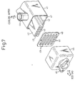
FIG. 7 to FIG. 10 show a second embodiment of the
present invention, wherein FIG. 7 is a view of a
multipipe structure corrosion resistant heat exchanger,
FIG. 8 is a view of an elliptically shaped tube and inner
fins, and FIG. 9 is a view of a rectangularly shaped tube
and inner fins.
-
The multipipe structure high corrosion resistance
heat exchanger of the present embodiment is an EGR gas
cooler for exchanging heat between engine cooling water
and EGR gas to cool the EGR gas and is comprised of a
housing 41 through which the engine cooling water
(corresponding to the heat exchange medium of the present
invention) flows, elliptically shaped tubes 42 arranged
in the housing 41, through which the EGR gas
(corresponding to corrosive fluid of the present
invention) flows, and made of stainless steel, and inner
fins 43 arranged inside the elliptically shaped tubes 42
all brazed together.
-
The housing 41 is formed integrally into a
rectangularly shaped tube by for example pressing
stainless steel and is provided with an inlet pipe 44 for
supplying cooling water inside and an outlet pipe (not
shown) for discharging the cooling water from the
outside. At one end of the housing 41 in the tube
direction is brazed a container-shaped first tank plate
45. At the other end of the housing 41 in the tube
direction is brazed a container-shaped second tank plate
(not shown). At the ceiling part of the first tank plate
45 is brazed a connecting part (flange) 46 to which a gas
inlet pipe (not shown) for supplying EGR gas into the
housing 41 is connected. At the ceiling part of the
second tank plate is connected a connecting part (joint)
to which a gas outlet pipe (not shown) for discharging
EGR gas from inside the housing 41 is connected.
-
The elliptically shaped tube 42 corresponds to the
fluid channel of the present invention and is stacked at
equal intervals in the vertical direction shown in the
cooling water passage (fluid passage) 47 formed in the
housing 41. One end of each elliptically shaped tube 42
is inserted into and brazed with an elongated hole 42 of
the first core plate 48 comprising the first header along
with the first tank plate 45. The other hand of the
elliptically shaped tube 42 is inserted into and brazed
with an elongated hole of the second core plate
comprising the second header along with the second tank
plate. Here, it is also possible to use rectangularly
shaped tubes 50 as fluid channels or to comprise the
fluid channels by a plurality of parts. Further, while a
single column of fluid channels was shown in the figure,
two or more columns may also be provided.
-
The inner fins split the fluid passage formed in the
elliptically shaped or rectangularly shaped tubes 42 and
50 into a plurality of fluid passages and thereby
increase the heat exchange area and improve the heat
conduction rate to improve the heat exchange performance
between the cooling water and EGR. The inner fins 43, as
shown in FIG. 10, are formed integrally in substantially
wave-like shapes from a thin stainless steel sheet and
include a top part 51, a side wall 52 bent in a direction
substantially perpendicular from the illustrated right
end of the top part 51 (downward direction in
illustration), a bottom part 53 bent in a direction
substantially perpendicular from the illustrated bottom
end of the side wall 52 (right direction in
illustration), a side wall 54 bent in a direction
substantially perpendicular with the illustrated right
end of the bottom part 53 (upward direction in
illustration), and so on.
-
In this embodiment, one or both end faces of the
brazing parts of the housing (corresponding to the first
joining member of the present invention) 41 and second
core plate (corresponding to second joining member of the
present invention) 48, the brazing parts of the housing
(corresponding to the first joining member of the present
invention) 41 and second tank plate (corresponding to
second joining member of the present invention) 45, the
brazing parts of the first and second core plates
(corresponding to the first joining member of the present
invention) 48 and first and second tank plates
(corresponding to second joining member of the present
invention) 45, the brazing parts of the elliptically
shaped or rectangularly shaped tubes (corresponding to
the first joining member of the present invention) 42 and
50 and the first and second core plates (corresponding to
second joining member of the present invention) 48, and
the brazing parts of the elliptically shaped or
rectangularly shaped tubes (corresponding to the first
joining member of the present invention) 42 and 50 and
inner fins (corresponding to second joining member of the
present invention) 43 may be given chrome platings and
Ni-P platings by either electroless or electro plating in
the same way as in the first embodiment.
-
Further, by heating at a brazing temperature higher
than the melting point of the nickel-based brazing filler
metal layer 22 and lower than the melting point of the
chrome-based brazing filler metal layer 21 (1000 to
1050°C) in the state with the chrome-based brazing filler
metal layer 21 and the nickel-based brazing filler metal
layer 22 interposed between the first and second joining
members so as to melt the nickel-based brazing filler
metal and cause the nickel-based brazing filler metal to
flow between the brazing parts of the first and second
joining materials to braze them together, a multipipe
high corrosion resistance heat exchange made of stainless
steel is produced. Further, as another embodiment, it is
possible to give the two end faces or either end face of
the brazing parts of the first and second joining members
a chrome plating and further an Ni-P plating by either
electroless or electro plating, then give a Cu plating by
either electroless or electro plating.
-
For joining the first and second core plates 48 and
the first and second tank plates 45 among these, it is
also possible to coat a paste of a nickel brazing filler
metal. Further, even if plating the two end faces of the
brazing parts of the joining members, it is possible to
give only one a chrome plating and Ni-P plating by either
electroless or electro plating. For example, in the core
part of a multipipe high corrosion resistance heat
exchanger, it is possible to give a chrome plating and a
Ni-P plating by either electroless or electro plating to
only the two end faces of the elliptically shaped or
rectangularly shaped tubes 42 and 50, plate only the two
end faces of the inner fins 43, or give a chrome plating
and Ni-P plating by either electroless or electro plating
to only the two end faces of the first and second core
plates 48.
-
Further, it is possible to divide the elliptically
shaped or rectangularly shaped tubes 42 and 50 into two,
give the two end faces of the tube parts a chrome plating
and Ni-P plating by either electroless or electro plating
and then braze them together to obtain the elliptically
shaped or rectangularly shaped tubes 42 and 50. In this
case, even without plating the inner fins 43 with either
chrome or Ni-P, the elliptically shaped or rectangularly
shaped tubes 42 and 50 and the inner fins 43 can be
brazed together and the elliptically shaped or
rectangularly shaped tubes 42 and 50 and the first and
second core plates 48 can be brazed together.
Other Embodiments
-
In the above embodiments, the first and second
shaped plates 1 and 2 forming the fluid channels 3 of the
high corrosion resistance heat exchanger were given
nickel-based platings after being processed into the
shapes of the parts, but it is also possible to plate the
materials before processing to give an Ni-P plating by
either electroless or electro plating and then process
them into the shapes of the desired parts. Further, in
the above embodiments, the two end faces of the first and
second shaped plates 1 and 2 and other first and second
joining members were given chrome platings and Ni-P
platings by either electroless or electro plating or
given chrome platings, Ni-P platings by either
electroless or electro plating, and Cu platings by either
electroless or electro plating, but it is also possible
to give one or both end faces of either joining members
of the first and second shaped plates 1 and 2 or other
first and second joining members chrome platings and Ni-P
platings by either electroless or electro plating or give
chrome platings, Ni-P platings by either electroless or
electro plating, and Cu platings by either electroless or
electro plating. Further, it is possible to give only the
brazing parts of at least one of the joining members
among the brazing parts of the first and second shaped
plates 1 and 2 or other first and second joining members
chrome platings and Ni-P platings by either electroless
or electro plating or give chrome platings, Ni-P platings
by either electroless or electro plating, and Cu platings
by either electroless or electro plating.
-
In the above embodiments, both end faces of the
first and second shaped plates were plated with nickel
and phosphorus, but it is also possible to plate nickel
and phosphorus on only one end face of at least one
shaped plate among the first and second shaped plates 1
and 2. Note that it is also possible to plate with nickel
and phosphorus one or both end faces of the inner fins 7
comprised of the stainless steel. By plating various
elements with a nickel base (plating of several layers
also possible) and brazing in this way, a metal layer
(alloy layer) superior in corrosion resistance can be
obtained. As a brazing filler metal layer and plating
layer, there are for example electroless nickel-based
alloy plating layers such as Ni-P-W, Ni-P-Cu, Ni-P-Cr,
and Ni-P-Co. These may be combined according to their
melting points to obtain Ni alloys. Further, the present
invention is not limited to a high corrosion resistance
heat exchanger or other heat exchanger and may also be
used for brazing together first and second plate-shaped
members, brazing together first and second tubular-shaped
members, brazing together a plate-shaped member and
tubular-shaped members, brazing together first joining
members and second joining members in a cross-shape or X-shape,
brazing together first and second joining members
where the second joining member is inserted into a
through hole of the first joining member, etc.
-
According to the first and fourth aspects of the
invention, since a brazing filler metal layer containing
chrome, which has a high corrosion resistance, is formed
between the joined parts of first and second joining
members comprised of stainless steel, the corrosion
resistance is excellent. Further, since a finer metal
structure comprised of chrome, nickel, phosphorus, iron
(diffused from the stainless steel), etc. can be realized
in the brazing filler metal, the occurrence of cracks at
the grain boundaries of the metal structure can be
reduced. Therefore, by using chrome plating and nickel-phosphorus
plating as the brazing filler metal layer
interposed between the first and second joining members,
the first and second joining materials can be brazed
together without any need to use an expensive paste of
the nickel brazing filler metal or nickel brazing filler
metal foil. Due to this, it is possible to eliminate the
step of coating or preplaced brazing, so a brazing method
of an inexpensive brazement can be provided.
-
According to the second and fifth aspects of the
invention, since copper is plated over a brazing filler
metal layer containing chrome, which has a high corrosion
resistance, between brazing parts of first and second
joining members comprised of stainless steel, it is
possible to realize a finer metal structure comprised of
chrome, nickel, phosphorus, copper, iron (diffused from
the stainless steel), etc. in the brazing filler metal,
so it is possible to prevent cracks at the grain
boundaries of the metal structure.
-
According to the sixth aspect of the invention,
since a brazing filler metal layer containing chrome,
which has a high corrosion resistance, is formed between
the brazing parts of first and second shaped plates
comprised of stainless steel in a corrosion resistant
heat exchanger where the brazing parts of the first and
second shaped plates are exposed to a corrosive
environment through which a corrosive fluid flows, the
corrosion resistance is excellent. Further, since a finer
metal structure comprised of chrome, nickel, phosphorus,
iron (diffused from the stainless steel), etc. can be
realized in the brazing filler metal, the occurrence of
cracks at the grain boundaries of the metal structure can
be reduced. Therefore, the same effects can be achieved
as in the fourth aspect of the invention, so a method of
production of an inexpensive corrosion resistant heat
exchanger can be provided.
-
According to the seventh aspect of the invention, by
copper plating a brazing filler metal layer containing
chrome, which has a high corrosion resistance, between
brazing parts of first and second shaped plates comprised
of stainless steel, it is possible to realize a finer
metal structure comprised of chrome, nickel, phosphorus,
copper, iron (diffused from the stainless steel), etc. in
the brazing filler metal, so it is possible to prevent
cracks at the grain boundaries of the metal structure.
-
While the invention has been described with
reference to specific embodiment chosen for purpose of
illustration, it should be apparent that numerous
modifications could be made thereto by those skilled in
the art without departing from the basic concept and
scope of the invention.
-
The present disclosure relates to subject matter
contained in Japanese Patent Applications No. 2000-136693,
filed on May 10, 2000, and No. 2001-57725, filed
on March 2, 2001 the disclosure of which is expressly
incorporated herein by reference in its entirety.