EP1152797B1 - Method of operating an ion beam therapy system with monitoring of beam position - Google Patents
Method of operating an ion beam therapy system with monitoring of beam position Download PDFInfo
- Publication number
- EP1152797B1 EP1152797B1 EP00909135A EP00909135A EP1152797B1 EP 1152797 B1 EP1152797 B1 EP 1152797B1 EP 00909135 A EP00909135 A EP 00909135A EP 00909135 A EP00909135 A EP 00909135A EP 1152797 B1 EP1152797 B1 EP 1152797B1
- Authority
- EP
- European Patent Office
- Prior art keywords
- treatment
- isocentre
- treatment beam
- profile
- radiation
- Prior art date
- Legal status (The legal status is an assumption and is not a legal conclusion. Google has not performed a legal analysis and makes no representation as to the accuracy of the status listed.)
- Expired - Lifetime
Links
Images


Classifications
-
- G—PHYSICS
- G21—NUCLEAR PHYSICS; NUCLEAR ENGINEERING
- G21K—TECHNIQUES FOR HANDLING PARTICLES OR IONISING RADIATION NOT OTHERWISE PROVIDED FOR; IRRADIATION DEVICES; GAMMA RAY OR X-RAY MICROSCOPES
- G21K5/00—Irradiation devices
- G21K5/04—Irradiation devices with beam-forming means
-
- A—HUMAN NECESSITIES
- A61—MEDICAL OR VETERINARY SCIENCE; HYGIENE
- A61N—ELECTROTHERAPY; MAGNETOTHERAPY; RADIATION THERAPY; ULTRASOUND THERAPY
- A61N5/00—Radiation therapy
- A61N5/10—X-ray therapy; Gamma-ray therapy; Particle-irradiation therapy
- A61N5/1048—Monitoring, verifying, controlling systems and methods
-
- G—PHYSICS
- G21—NUCLEAR PHYSICS; NUCLEAR ENGINEERING
- G21K—TECHNIQUES FOR HANDLING PARTICLES OR IONISING RADIATION NOT OTHERWISE PROVIDED FOR; IRRADIATION DEVICES; GAMMA RAY OR X-RAY MICROSCOPES
- G21K5/00—Irradiation devices
- G21K5/10—Irradiation devices with provision for relative movement of beam source and object to be irradiated
Definitions
- the present invention relates to a method for operating of an ion beam therapy system under supervision of Beam position, which is operated especially with heavy ions becomes.
- a procedure is described in G. Kraft, Radiotherapy with heavy charged particules, 6th International meeting on progress in Radiooncology, - 1998.
- This document is related especially on the spatial deviations of the Beam position, and discloses a method with the in Preamble of claim 1 defined features.
- Ion beam therapy systems are preferred for treatment used by tumors. They have the advantage that when irradiated the largest part of a target Energy of the ion beam is transferred to the target while only transfer a small amount of energy to healthy tissue becomes.
- a relatively high radiation dose used to treat a patient. X-rays however, transfer their energy equally the target as well as healthy tissue, so that from health No high dose of radiation to protect the patient can be used.
- An ion beam therapy system is, for example, from US Pat. No. 4,870,287 known from a proton source
- Proton beams are generated whose protons are over an accelerator device different treatment or Irradiation places can be supplied.
- a rotating stand with a patient bed is provided, so that the patient with the proton beam under different Irradiation angles can be irradiated.
- the accelerator device includes the combination of a linear accelerator (Linear Accelerator, LINAC) and a so-called synchrotron ring.
- a monitoring device for monitoring that supplied by the raster scanner Treatment beam provided.
- This monitoring device is between the last deflecting magnet of the above magnet arrangement and the isocenter and can ionization chambers for monitoring particle flow and multi-wire chambers for monitoring the beam position and beam width include.
- the present invention is therefore based on the object a method for operating an ion beam therapy system to propose adequate operational security and Operational stability, particularly with respect to the treatment jet, is guaranteed.
- the method should in particular be suitable for use with heavy ions.
- the present invention relates to an ion beam therapy system, which one arranged in a beam guidance system Raster scanner device with vertical deflection means and horizontal ones Deflection means for vertical or horizontal deflection of a treatment beam perpendicular to its beam direction includes so that the treatment beam from the raster scanner to an isocenter of the radiation site is deflected and a certain one that surrounds the isocenter Scanned area.
- the beam position of the treatment beam is monitored in the area of the isocenter and evaluated, being in the ion beam therapy system intervenes if the evaluation of the beam position a deviation from a predetermined target value results, which a certain, to a required half-width of the Beam profile related tolerance value exceeds.
- This tolerance value can in particular be ⁇ 25% of the required Half width of the treatment beam.
- the definition of the intervention threshold relative to the full width at half maximum the beam profile has proven to be practical since all geometric parameters of the radiation plan with scale the full width at half maximum and especially those for patient operation required quality of the generated particle coverage is achieved.
- the absolute Beam profile width and / or the variation (fluctuation) the number of particles in the treatment beam measured and evaluated in order to reach the selected intervention thresholds in a suitable manner in the ion beam therapy system intervene.
- the present invention enables a significant improvement the operational stability and operational safety of the ion beam therapy system and defined a test plan with certain Test aspects, which in the sense of an acceptance test and / or a constancy test of the ion beam therapy system can be carried out.
- the present enables Invention by regulation on the raster scanner magnet an adjustment of the treatment beam in such a way that the specified tolerance values are observed, so that, for example an accurate and also automatic by control the position scanner of the raster scanner magnet Treatment beam can be achieved.
- An ion beam therapy system on which the present invention is based is generally used in hospital buildings which are divided into a medical area and an accelerator area.
- Several treatment or radiation stations are provided for the treatment of patients.
- the control system of the ion beam therapy system comprises several control rooms, whereby technical control rooms and a main control room for the accelerator device can be provided for the individual treatment places.
- laboratories for dosimetry or accelerator maintenance or a PET facility P ositron- E mitter- T omograph
- energy supply devices in particular for the accelerator device and the radiation system
- cooling devices are provided.
- the individual treatment rooms are delimited by thick walls and ceilings, which consist for example of concrete with a thickness of 2 m, in order to ensure a sufficient shielding effect.
- the ion beam therapy system comprises an injection system, which together with the previously mentioned accelerator device is shown in simplified form in FIG. 1.
- the injection system comprises ion sources 1, their radiation each with a low-energy beamline Arrangement of spectrometer magnets and quadrupoles one Switching magnets are supplied, which, among other things, the radiation via another quadrupole arrangement and one for pulse shaping provided chopper arrangement a linear accelerator 2 (Linear Accelerator, LINAC).
- ion sources 1 their radiation each with a low-energy beamline Arrangement of spectrometer magnets and quadrupoles one Switching magnets are supplied, which, among other things, the radiation via another quadrupole arrangement and one for pulse shaping provided chopper arrangement a linear accelerator 2 (Linear Accelerator, LINAC).
- LINAC Linear Accelerator
- the linear accelerator 2 is used for the first acceleration of the ions supplied to it, which are then fed via an injection line 4 are fed to the synchrotron 5.
- the injection line 4 includes in addition to the stripper already mentioned 3 another chopper arrangement for fine shaping of the injection pulses, Dipole magnets for charge analysis, quadrupoles for adaptation of radiation to the absorption capacity of the synchrotron 5 etc.
- the injection system which i.a. the ion sources 1, the Low-energy beamline, the linear accelerator 2 (LINAC), stripper 3 and injection line 4 comprises, therefore, has the overall task of having ion beams desired particles to generate and analyze the contamination to monitor the ion beams and the ion beam intensity to control the ions at a certain injection energy to accelerate as well as the pulse length of the in to determine the synchrotron ring 5 injected pulses.
- LINAC linear accelerator 2
- the synchrotron ring 5 is used for final acceleration of the ions supplied to it to a certain energy and includes for example several deflection magnets, quadrupoles and sextupoles. In the embodiment shown in Fig. 1 are for example six deflection magnets with a deflection angle of provided 60 ° each. Within the synchrotron 5 is one Cooling device (not shown) arranged. By multiple Injection cycles are the injected ions from an energy in the range of a few MeV / u to an energy of, for example accelerated over 400 MeV / u. That way accelerated treatment beam is directed at a particular Place the synchrotron over a high-energy beam line 6 extracted and fed to the individual treatment places.
- the high-energy beam guide line 6 comprises quadrupole lenses, Deflection magnets, beam analysis devices, etc.
- another chopper can be located behind the extraction point the synchrotron 5 can be arranged, which is used in emergencies comes to cut off the beam. Besides that, can a routine interruption of the extraction process, the for decoupling the treatment beam from the synchrotron 5 serves to be provided after each raster scan section.
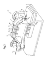
- Fig. 2 shows a perspective view of one of the rotating stands 8, each provided at one of the treatment places are to whom the treatment beam over the previously described High-energy beam line 6 is supplied.
- the rotating structure 8 rotates around a certain axis of rotation, while one closes treating patient on a patient couch 9 with local fixed orientation or alignment.
- the one to be treated The patient's body is located in the isocenter 10 of the treatment beam, with the isocenter as the point of intersection between the central beam 11 of the following even closer described raster scanner and an axis of rotation of the patient couch 9 is defined.
- the high-energy beam line 6 designed such that the treatment beam deflected several times after entering the rotating stand 8 in one plane becomes.
- the first two dipole magnets 7 have identical deflection angles, for example 42 ° and are opposed to each other while it the last dipole magnet 7 with a deflection magnet is a deflection angle of 90 °, so that the treatment beam 11 after entering the rotating stand 8 first from the The axis of rotation of the rotating stand 8 is laterally deflected and then is guided parallel to the axis of rotation of the rotating stand 8 then from the last deflecting magnet 7 via a Beam exit opening at an angle of 90 ° with respect to exit the patient bed 9.
- the one provided in the present ion beam therapy system Raster scanner arrangement is the one shown in FIG. 2 Embodiment between the last quadrupole lens 12 and the last deflecting magnet 7 of the rotating stand 8 and comprises at least one horizontal raster scanner magnet 13 and at least one vertical raster scanner magnet 14.
- the raster scanner magnets 13 and 14 guide the ion beam 11 each perpendicular to the beam axis 11 either horizontally or vertically, so that the ion beam scanned in this way 11 after leaving the last deflecting magnet 7 in agreement with a given treatment plan a certain scans the area surrounding isocenter 10.
- the raster scanner magnets 13, 14 are by a (not shown) Controlled control device, which is part of the Overall control system of the ion beam therapy system is.
- monitoring means In the area between the beam outlet opening of the last deflecting magnet 7 and the isocenter 10 are monitoring means provided for monitoring the treatment beam 11.
- This Monitoring means which for example for recording and Regulation of the beam position, beam shape and particle flow are provided, are explained in detail below.
- a positron-emitter tomograph can also be used (PET) to monitor the radiation process be provided, the image sensor (camera) is aligned in an in-beam position.
- Positron emitter tomography is preferred during treatment or radiation performed. Strikes a treatment beam on tissue, starting from the primary ions positrons emitting isotopes. Some of these isotopes, which from the primary ions only by the loss of one or distinguish two neutrons stop almost in the same Area like the corresponding primary ions. This stop point the so-called positron emitter can be used to monitor the radiation process with the help of positron emitter tomography be determined.
- a first section of the test system concerns production the treatment beam 11.
- the monitoring means indicated in FIG. 2 include an absorber ionization chamber system, which on To arrange isocenter 10 of the respective treatment place is.
- the absorber ionization chamber system measures for a few selected ones Energy levels generated during a therapy test cycle activated, the location of the Bragg peak at the treatment site, where the instantaneous beam energy is the measured position of the Bragg peak. For determination the position of the Bragg peak, the Bragg curves in measured fine steps. Should look at the review a deviation of the Bragg peak from the target position by more Intervention is required as 0.5 mm. To Constancy testing can be performed using the test procedure described above every radiation block.
- Another sub-point regarding the examination of the treatment beam relates to the monitoring of the intensity level of the slowly extracted treatment beam at the irradiation or treatment site.
- the limited dynamic range of the raster scanner limits the scanning or scanning speed of the rastered treatment beam upwards, the component relevant for this limitation being the maximum rate of current rise of the magnetic power supply devices.
- the scanning speed of the treatment beam depends on the intensity of the beam and the planned particle loading. In order to ensure that the maximum scanning speed is not reached during the irradiation, the particle rate extracted from the synchrotron 5 must not significantly exceed the target value.
- the control or monitoring or monitoring system then possibly being operated in the area of very small input currents, which can impair the precision of the beam detection. Therefore, in the present therapy system, a measurement and logging of the particle intensities in the synchrotron in the upper intensity range and the particle rate supplied to the irradiation site are provided for all intensity steps for several energy over a few minutes.
- the particle rate supplied by the accelerator to the radiation site is between 2 x 10 6 and 2 x 10 8 ions per extraction from the synchrotron 5.
- the deviation of the particle rate from the target specification may be a maximum of 30% upwards and a maximum of 50% downwards. If these limits are exceeded, appropriate intervention is required. To check the constancy of the therapy system, this check can be carried out daily, for example.
- the radiation planning and raster scan programming must be the same Dependencies of the energy, intensity and focus variation be taken as a basis. To ensure this should the accelerator side after the last therapy programming created file entries compared with those be used for raster scan programming and radiation planning be used. A discrepancy in these file entries is not permitted. To check consistency, this should Checking should be done before each radiation block.
- the extraction of the treatment beam from the synchrotron 5 must be able to be stopped within less than 1 ms after a corresponding signal from an interlock unit of the therapy system. This is done by quickly switching off a special quadrupole in the synchrotron 5.
- the time between a request to abort the beam by the control and security system and the absence of the beam at the irradiation site is of crucial importance both for the raster scanning process when changing successive isoenergy sections, which have constant energy correspond to the areas to be irradiated, as well as for a possible emergency shutdown of the system in the event of a fault.
- a test is therefore provided which measures the total time, ie both the response time of the request and that of the beam abort.
- the control system For this purpose, the control system generates a corresponding signal which simulates the termination of an isoenergy section, or an interlock condition, ie a condition for an emergency shutdown, is generated.
- the control system measures the number of particles after an interruption, which may not be greater than 10 4 particles / s 1 ms after the interruption.
- a measurement is carried out with a storage oscillograph and a pulser, which are permanently installed in the technical control room of the therapy system, which evaluates the output signal of the current-voltage converter of one of the ionization chambers in order to check the measurement of the control system described above. Even with this second measurement, no beam should be detectable 1ms after termination.
- the following times of termination should be checked one after the other: at the beginning of the extraction time, in the middle of the extraction time, at the end of the extraction time and outside the extraction time. The check should be carried out daily as a constancy check.
- a log can be created which shows the settings essential accelerator components during the irradiation and selected beam diagnosis measurement results are documented.
- the functionality of the logging and the log content to test it is suggested to use a reference therapy cycle to activate and call the protocol program. You can then create the log program Log data compared to the expected data , if the protocol is incomplete or Intervention if there is a logged device error must be done. This test procedure can be used to check consistency be carried out before each radiation block.
- a second section of the test system concerns verification the guidance of the treatment beam (in front of the radiation site).
- a third section of the inspection system concerns the inspection the beam guidance at the radiation site.
- the zero point position of the treatment beam is monitored.
- To be exact Beam positioning at isocenter 10 after deflection of the To ensure beam 11 by the raster scanner magnets 13, 14 the axial position of the treatment beam 11 must be in the last Part of the beam path to the radiation site for the whole Energy and focus area are checked.
- To this Purpose are profile grid 16 behind the raster scanner magnet 13 and 14 and at the beam exit window in the beam path retracted and test cycles across the entire energy and focus range generated. The profile grids are individually evaluated and the beam parameters recorded thereby logged. When measuring the one arranged at the beam exit window Profile grid must be the profile grid arranged in front of it 16 can be moved out.
- the beam position and the Beam angle can be determined. From the beam positions of the Profile grid becomes the expected position of the treatment beam determined at isocenter 10 and then the protocol checked. If there is a position error for the isocenter 10 of ⁇ 25% with regard to the required beam half-widths a corresponding intervention must be carried out. This test can be performed daily to check consistency become.
- the absolute Beam location and the spatial stability of the treatment beam checked at the radiation site Compliance with the absolute Beam position is the prerequisite for implementation treatment or radiation plans. Therefore the absolute Location with location-sensitive detectors of the control system be measured.
- the relative spatial stability of the treatment beam in the isocenter of the radiation site, the accuracy determines with which an irradiation plan is carried out can.
- the location of the treatment beam is online, i.e. continuously, measured and checked during irradiation. In the event of deviations from the target location within one of the radiation plan The irradiation is stopped in accordance with the predetermined tolerance limit or an appropriate intervention.
- Everyone location-sensitive detector is checked separately.
- the test is made with a profile grid and location sensitive Detectors, e.g. Multi-wire chambers.
- the absolute beam position in isocenter 10 using a light target or film on Checked the location of the isocenter.
- the treatment beam 11 With the raster scanner magnets 13, 14, the treatment beam 11 becomes static deflected into the isocenter 10 and by the profile grid measurement obtained spatial coordinates with the specified target values compared. For example, this can be done on a regular basis Distances, e.g. at about every tenth energy step become.
- the absolute beam position with the multi-wire chambers should have a calibration of their absolute positions be performed.
- the beam zero point determined from the film is compared with that calculated from the multi-wire chambers.
- the difference or deviation then results in correction offset values for the location calculation.
- These correction offset values are taken into account in the position setpoints, whereby the absolute position of all five points compared becomes.
- Another aspect of this test section includes monitoring and control of the absolute beam profile width and the temporal stability.
- the accelerator device upon request by a pulse center control of the control system delivered beam focusing must be observed because the treatment or radiation plans are based on these values based.
- the absolute beam profile width in isocenter 10 with the help of a profile grid checked, the position of the profile grid with the by Laser cross made visible on a light target or film Isocenter is adjusted.
- the treatment beam is deflected statically into the isocenter, this, for example, at about every tenth energy step can be done.
- the ones obtained with the profile grid measurement Beam widths are compared with specified target values, regulation taking place such that a maximum Deviation of the beam width of ⁇ 50% from the target specification observed becomes. This applies in particular to the energy sector above 200 MeV / u.
- the constancy test of the ion beam therapy system can in turn with the multi-wire chambers already described above, which are at a distance of 970 mm or 790 mm the isocenter 10.
- a calibration of the absolute width measurement of the two Multi-wire chambers A film with horizontal and irradiated vertical stripes, each beam with a Extraction from the synchrotron with a fixed focus is produced. In this way, depending on the selectable Focusing, for example, creates seven beams become.
- the beam widths determined on the basis of the irradiated film with the multi-wire chambers (local chambers) measured measured in order to obtain correction offset values therefrom, which is then taken into account again in the target values can be.
- FIGS. 3A / B and 4A / B correspond to an enlarged view of the diagrams shown in FIGS. 4A and 4B.
- Fig. 3A / 4A beam positions without the previously proposed position control
- Fig. 3B / 4B beam positions with the position control shown. From the illustrations it can be seen that by using the position control etc. a clear more stable beam position can be achieved while it is without Position control sometimes too large deviations from the desired beam position comes.
- Another aspect of this test section concerns monitoring the number of particles in the treatment beam, i.e. The supervision the variation in the number of particles.
- To the measuring range for Particle number measurements should not be too large the intensity of the treatment beam delivered by the accelerator fluctuate only within certain tolerance limits.
- the intensity is suggested of the treatment beam using the ionization chambers in Measure connection with the measuring equipment of the control system and to average the number of particles over a time window of 300 ⁇ s.
- the subsequently measured particle numbers may be within of the time window is five times the previous value recorded mean correspond to not an intervention trigger.
- the target positions all moving parts between the last deflecting magnets the high-energy beam line 6 and the bogie 8 be checked regularly since everyone is in the Beam guidance object to an impairment the beam quality at the radiation site. It must therefore ensure that there are no moving parts of the Beam guidance is in the beam path. For this purpose are on the corresponding moving parts limit switch attached, their states automatically and individually by the control system can be checked. This should be for constancy testing be repeated before each block of irradiation.
- a fourth section of the inspection system concerns inspection of features, which with the radiation control unit of the Ion beam therapy system related.
- the ionization chambers of the monitoring or monitor system of the therapy system generated electrical Charge used to determine the number of particles, depends on the pressure and temperature of the ionization chamber gas off so that these two quantities are monitored during the irradiation and must be logged.
- the pressure and the temperature of the gas in the ionization chambers are generated using electrical sensors measured, the measured values about once per minute recorded by the control system and with registered Calibration factors converted into absolute units (hPa and ° C) and displayed digitally. The course of time of the Measured values can be displayed graphically in a trend diagram become.
- the sensors are made with the help of reference measuring devices calibrated. Calibration of those installed in the ionization chambers Sensors should be placed before each therapy block be repeated.
- Another test aspect concerns the switching of the currents for the deflection magnets 13, 14 of the raster scanner. It must be ensured be that the current values of these deflection magnets one certain setpoint set for the magnetic power supplies both in terms of value and in terms of time within certain Reach tolerance limits. For this purpose, the time between the setting of a magnetic current value in the magnetic power supplies and reaching the corresponding stable magnetic current measured for different current values.
- the tolerable maximum current accuracy with regard to a deviation from the set Magnetic current value is 0.3 A.
- a fifth section of the test system relates to verification the functionality of the interlock unit already described of the ion beam therapy system.
- the interlock unit monitors during operation for example the signals of the limit switches described above of the moving parts in the beam guidance, the states of the Magnetic power supplies of the raster scanner magnets 13 and 14, the ionization chambers in terms of power supply, one Data overflow of data transmission, compliance with the intensity limit values and the synchronization of the individual ionization chambers, the electronics of the beam position measuring device as well as the beam position itself, the high voltage and the gas flow of the individual detectors, a possible interlock the sequence control computer, the position of the patient bed, a possible interruption in the immobilization of the patient (e.g.
- the functionality of the manual emergency shutdown can be checked via the medical control panel as a manual Emergency shutdown must be guaranteed at all times.
- a sixth section of the test system concerns the review of medical facilities for patient positioning of the ion beam therapy system.
- the accuracy of the stereotactic Coordinate determination of a target point using a CToder MR procedure to be checked because of the accuracy of the stereotactic imaging an essential factor for the Overall accuracy of radiation is.
- any target point within a spherical phantom a special test specimen are represented, the center of which easily visible with the help of imaging techniques can be represented.
- the spherical phantom is used in the stereotactic Frame clamped so that the center point to an unknown Target point is.
- the stereotactic Coordinates using the applied X-ray, CT or MR methods sequentially determined, with the tomographic
- the layer spacing should be 1 mm.
- the accuracy of the X-ray method is accurate to 1/10 mm the accuracy of the target point determination with CT and MR can be determined by comparison with the X-ray method, i.e. it becomes the radial distance between that with the x-ray determined position of the target point and that with the Checked position determined by CT or MR method.
- the radial The distance must not be more than 1.5 mm. For constancy testing It is sufficient to carry out this test annually.
- the accuracy is suggested as a further test aspect the position of the isocenter between the axis of rotation of the patient bed 9 and the central beam 11 of the raster scanner 13, 14 check as the intersection between the axis of rotation of the Patient couch 9 and the central beam 11 of the raster scanner 13, 14 isocenter defined the connecting element in the Positioning between planning and radiation is.
- a constancy test should be done before each radiation block become.
- the position of the isocenter in relation to the central beam 11 is the position of the isocenter by definition on the axis of rotation the patient bed 9 below the straight beam level fixed and related by an optical measurement system noted on wall markings.
- Checking the position of the test specimen with respect to the central beam 11 takes place with Using a film measurement, a verification film in Beam direction seen behind the test specimen with a (non-screened) Central beam is irradiated, the full width at half maximum is larger than the diameter of the test specimen, so that the position of the test specimen on the verification film with respect to the central beam. In this case lies the intervention threshold in the event of a maximum deviation 25% of the full width at half maximum of the primary beam.
- the accuracy of the laser adjustment to the isocentre 10 are checked because the lasers mark the isocenter 10.
- the lasers are positioned after the test specimen in the isocenter 10 with the aid of optical measurement aligned to the center of the specimen and the deviation the laser lines from the horizontal or vertical checked, the maximum deviation being 1 mm each may.
- the imaging of the laser is on marked on the opposite walls or on the floor and then serves as a reference.
- Another test aspect concerns the accuracy of the adjustment of the X-ray tubes and the cross on the opposite Recording stations, since the X-ray procedure is an additional one Is a method for marking the isocenter 10.
- X-rays are taken in the three spatial directions and the distance of the image between the test specimen and the target on the X-ray image.
- the test specimen should be reproduced exactly on the image of the target cross, so that the maximum distance between the image of the specimen and the target cross may be 1mm.
- the patient Due to the isocentric radiation the patient must also the accuracy of the display of the angular scale of the isocentric Rotation of the patient bed 9 can be checked, this similar to the regulations of DIN 6847-5, point 12.2.4 can.
- the maximum tolerable inaccuracy is 1 °.
- the spatial stability of the isocentric rotation should the patient bed 9 are checked because of the definition of the isocenter 10 requires a corresponding stability.
- This check can be carried out analogously to DIN 6847-5, point 14.2 be carried out, the intervention threshold at a Inaccuracy is 1 mm.
- the accuracy of patient positioning is also suggested and positioning as an exact Patient positioning is a prerequisite for tumor-conforming Radiation is.
- the therapy system can do this the unknown stereotactic coordinates of the Center of a test specimen within the stereotactic Base ring was fixed, determined as the target point and the center using the stereotactic aiming device and by transversely moving the patient bed 9 into the isocenter 10 are brought. In this position, the three spatial directions x-rays and the distance the position of the test specimen from the target on the three images determined. The radial distance between the center point of the test specimen and the isocenter may not exceed 1.5 mm. Otherwise there is a corresponding correction of the patient positioning necessary.
- a seventh section of the test system concerns radiation planning, in the course of which, in particular, that for a specific one Irradiation intended radiation dose values calculated become.
- the identity of the values of the current basic data sets the corresponding values of a backup copy must be checked to ensure that the basic data sets are not uncontrolled have been changed.
- the comparison is also made here the content of the current basic data records with the backup copy with the help of a computer program, which in particular should be started before each radiation block.
- radiation planning systems is also a check of the reference values in the basic data set once a month required.
- This sub-item can be used in the current radiation planning with heavy ions, because the depth dose distributions, i.e. the energy loss data as a function of Depth, stored as absolute values with respect to the input fluence are. Thus, there is no special reference value for the Dose recorded.
- the basic data records used are already checked as described above.
- An essential aspect when considering the treatment planning is checking the accuracy of the ion beam therapy system automatically performed dose calculation for a planned radiation depending on the existing basic data and the dose calculation algorithms used, being here between the irradiation of a a homogeneous and an inhomogeneous medium can be distinguished. In either case, the dose calculation can be checked be performed using a phantom, as follows is described in more detail.
- the calculated dose for a homogeneous medium can in the radiation planning program of the ion beam therapy system several measuring points, for example 10 measuring points, in the calculated dose distributions or CT sections on which the calculated physical dose is experimental should be verified.
- the verification takes place in one Water phantom, being at the desired measuring points corresponding coordinates in the water phantom ionization chambers be positioned.
- the treatment planning program calculated for the individual measuring points in addition to the water energy dose values also their coordinates in the phantom used. Subsequently the phantom is used by the radiation planning program calculated control parameters irradiated, the of values recorded in the ionization chambers are converted into energy dose values to verify the calculated dose values.
- the verification is carried out for several treatment plans, preferably six typical radiation plans verified three of which were constructed on Target volumes in the water phantom and three plans for the radiation sourced from patients.
- the latter radiation plans are subsequently used as standard patient plans.
- the values calculated by the radiation calculation program serve as reference values for the constancy test to be carried out.
- the intervention threshold is that the deviation between the calculated and measured radiation dose values total, i.e. on average, a maximum of ⁇ 5% of the dose of Target irradiation volume may be. It also specifies that the maximum deviation for a single measuring point is ⁇ 7% may be.
- the procedure described above relates in particular for the acceptance test of the ion beam therapy system.
- For a consistency check only requires verification of each two of the standard plans described above to ensure consistency check the calculated dose distributions and this with the experimentally determined dose distributions to compare.
- the constancy test should be done before each radiation block be performed.
- the radiation calculation algorithms used and the approximation used for a inhomogeneous medium can be a spherical solid phantom be used, which is made of a water-equivalent material consists of individual layers in which to simulate different inhomogeneous bodies different Inhomogeneities can be used.
- These inhomogeneities are discs made of different tissue equivalents Materials (for example, according to the material of the Lungs, a soft or hard bone, of soft tissues or from solid water) or only air (if not used a disc) exist.
- too Phantom defined up to 10 measuring points for verification at which each the radiation dose from both the radiation planning program calculated as well with a set of simultaneously measuring ionization chambers detected and compared becomes.
- the dose calculations can be made using an irregular shaped test phantom are verified.
- a test phantom which consists of water equivalent Material exists and for example a human Reproduces head.
- a test phantom which consists of water equivalent Material exists and for example a human Reproduces head.
- the phantom up to 10 measuring points defined for verification.
- Another aspect when reviewing the treatment planning relates to the testing of those in the ion beam therapy system imaging techniques used to ensure correct Transfer of the geometric structures (e.g. the target irradiation volume and the contours of the patient) and the Planning parameters from imaging to positioning sure.
- the geometric structures e.g. the target irradiation volume and the contours of the patient
- the planning parameters from imaging to positioning sure.
- the calculated radiation dose values in the inhomogeneous medium used a phantom with disc or ring-shaped inserts in this case the inhomogeneous inserts also can have different diameters.
- the Phantom will take a picture and it will become from it obtained CT data for the three main directions in the bogie 8 (see FIG. 2) digital X-ray reconstructions are calculated.
- Monitoring is also required to increase operational safety the maintenance and further development of those in the ion beam therapy system used radiation planning programs required. After a further development of the radiation planning programs can accidentally use the wrong version become. To avoid this and to ensure that always the correct versions of the different modules
- the control system of the ion beam therapy system will be used designed in such a way that with each call a Treatment planning program version numbers with date of respective program are displayed by the user to be compared with data in a log book.
- An eighth section of the inspection system concerns the inspection the scanning process and dosimetry.
- a first test aspect of this test section concerns the Particle number monitors and monitoring means of the ion beam therapy system, which in the present embodiment - As has already been described - from large areas Ionization chambers exist.
- the constancy of the calibration factors of these ionization chambers must be checked, since the calibration factors may only change within the scope of fluctuations in air density.
- the two ionization chambers of the raster scanner are calibrated with regard to the number of particles per monitoring or monitoring unit of the ionization chambers.
- the calibration of the ionization chambers takes place via a dose measurement in a homogeneously rastered radiation field, the deviations from the reference conditions being corrected and the display of the ionization chamber being converted into a water energy dose D scan .
- M monitor units per coordinate point i of the ionization chamber.
- the relevant energy range (for example between 80 MeV / u and 430 MeV / u) is measured in several steps.
- the measuring location of the ionization chamber checked in each case is located in the isocenter 10, the ionization chamber or the dosimeter being arranged in a solid-state phantom.
- the same table of mass braking power of 12 C is used that is also used as the basis for the treatment planning.
- a set of calibration factors K is obtained as a function of the energy E and the step size ⁇ x, ⁇ y, it being determined that the deviation from the reference values may be a maximum of ⁇ 3% for each calibration factor.
- At least three values should be checked from the set of calibration factors. This test procedure should be carried out daily to ensure consistency.
- the dose consistency must also be checked, since the same preselected Monitor units of the ionization chambers always the same Dose indicators. It is therefore recommended that the Constant dose in the center of cube-shaped radiation volumes, that of the raster scanner or its magnet 13, 14 are generated or scanned, depending on the Check the set of calibration factors of the ionization chambers.
- the Dose measured in a phantom positioned in this way is that the isocenter 10 is exactly in the middle of its front Surface.
- the irradiation takes place within a radiation or dose cube with an edge length of 5 cm, its center as a measuring point in 11.3 cm water equivalent Depth is arranged. (The calculation of the tax data to generate the dose cube is done using the CT-based Treatment planning.
- the isocenter 10 it is more convenient the isocenter 10 to the location of the beam entry in to put the water phantom. Furthermore, the chosen one allows Measuring depth a standardization of the measuring equipment for the different tests.) The one determined in this way Irradiation dose is saved as a reference dose. The subsequently measured actual dose values can then be compared with this reference dose, with a maximum Deviation between the actual and the nominal Dose (reference dose) of ⁇ 3% is permitted. One should daily consistency check.
- the influencing parameters on the particle number monitors or Ionization chambers must be checked, taking particular care the dependence of the calibration factors K on the particle fluence and the particle flow is checked. In both cases an annual consistency check should be carried out.
- the measurements are carried out in a phantom, which is irradiated with an area of 5 ⁇ 5 cm 2 at the energies 150 MeV / u, 250 MeV / u and 350 MeV / u, each with the same beam intensity.
- An ionization chamber is arranged in the middle of the irradiated area.
- the monitor values of the ionization chamber are determined so that a dose of 0.2 Gy, 0.5 Gy or 1 Gy results at the measuring location.
- the correspondence between the actual and the nominal dose is recorded for these different monitor values, a maximum deviation of ⁇ 3% being permissible. Compliance with this narrow tolerance makes sense and is also feasible.
- the ionization chambers or particle number monitors should the dependence of their calibration factors on the Beam position can be checked. It will be essentially the same Procedure as for checking the constancy of the calibration factors carried out, however, the same arrangement as in the dose constant check described above becomes.
- the measurements are in an irradiation volume or radiation cubes of the raster scanner 13, 14 with a Edge length of 5 cm performed, but with a side Displacement of 2 cm and 6 cm.
- the monitor values the ionization chambers set such that in the In the middle of the radiation volume, a radiation dose of 1 Gy results.
- the value measured on the side should not exceed Distinguish 3% from the value measured in the middle. Also in this case an annual consistency check is recommended.
- Another test aspect of this test section concerns the Checking the dose distribution of the raster scanner 13, 14, wherein both the deep dose distribution and the transverse dose distribution is checked.
- the homogeneity of the depth dose distribution becomes dependent of a selected radiation energy and selected Monitor values per irradiation energy value of the ionization chambers used checked because the depth dose homogeneity is crucial depends on the chosen energy and its constancy.
- the ionization chambers be positioned so that not several ionization chambers be irradiated in succession.
- the edge lengths the radiation cubes are, for example, 2.5 cm, 5 cm and 10 cm, the measurements of the ionization chambers for Depths of the centers of the respective cube-shaped radiation volumes of 5 cm, 12.5 cm and 20 cm.
- the monitor values are taken from the treatment planning in the way that is in the middle of the respective radiation volume one specified by the treatment planning Radiation dose results. By comparing the actual Measured values with the reference values can vary the displays of the ionization chambers are checked. A maximum Deviation of ⁇ 5% is tolerable. If exceeded this tolerance limit must be changed in the system, to correct the excess deviation. For constancy testing the test procedure described above should be performed before each radiation block be performed.
- the cross-dose distribution of the raster scanner becomes dependent checked by the energy to ensure that the Homogeneity of the raster scanning method with all radiation energies used is guaranteed.
- fixed ionization chamber monitor values and each different Irradiation energies e.g. 100 MeV / u, 150 MeV / u, 200 MeV / u, 250 MeV / u, 300 MeV / u and 350 MeV / u
- in front of the dosimeters or ionization chambers free air a density distribution on a verification film generated.
- the radiation dose each about 1 Gy should be. It will be the standard deviation of the corrected Displays the ionization chambers or the verification film blackening checked within the radiation field, whereby a maximum deviation from the reference values of ⁇ 5% is tolerable is. Deviations from the reference values that cannot be tolerated are corrected to adapt to the actual to achieve existing measurement conditions. A constancy test should be done before each radiation block, with in this case the use of the verification film with surveillance the blackening of this verification film is sufficient.
- Another test aspect of this test section concerns the Checking the field geometry during the raster scanning process, whereby the dependence of the spatial position of a certain radiation volume the raster scanner 13, 14 of selected radiation energies is checked.
- Raster scanner 13, 14 cube-shaped or cuboid radiation volumes generated, with a constant particle assignment for every coordinate point of a layer (energy), but one different occupancy per shift is used that there is a homogeneous dose distribution in the radiation cube results.
- a wedge-shaped Illuminated solid-state phantom behind which is a verification film located. Then the position of the verification film blackening relative to the center of the radiation detected.
- the edge lengths of the radiation fields are for example 4 cm, 7 cm and 12 cm during the expansion the radiation cuboid or cube in the beam direction 2.5 cm, 5 cm and 10 cm.
- the measurements are there for water-equivalent depths of the center of the respective Irradiation volumes of 5 cm, 12.5 cm and 20 cm performed.
- the monitor values of the dosimeters or ionization chambers are determined from the treatment planning in such a way that in the middle of the irradiation volume by planning the irradiation given radiation dose.
- As field boundaries the locations are defined where the edge drop of the Darkness is 50% of the plateau value.
- the location of the distal Field boundaries as well as the lateral seen in the beam direction Field boundaries are checked and compared with reference values.
- test section concerns this test section the verification of the overall system to ensure accuracy the applied radiation dose with regard to their Verify the height and space of each patient to be irradiated to be able to ensure that the individual components of the system is guaranteed.
- an inhomogeneous phantom is again used, in which case irradiation planning is carried out as a one-time preparation for a hemispherical phantom made of a solid, water-equivalent material with a radius of, for example, 8 cm.
- irradiation planning is carried out as a one-time preparation for a hemispherical phantom made of a solid, water-equivalent material with a radius of, for example, 8 cm.
- the center of the phantom is located in isocenter 10 and the hemisphere of the phantom is opposite to the direction of irradiation.
- Different inhomogeneities for example in the form of disks with a diameter of 3 cm each, can be inserted into the phantom, preferably seven different materials or inhomogeneities with the following densities being used: No. density 1 0.001 (Air) 2 0.30 (Lung) 3 1.035 (solid water) 4 0.92 (Fat) 5 1.05 (Muscle) 6 1.14 (soft bone) 7 1.84 (hard bone)
- the planned target irradiation volume is for three different ones Beam directions with a beam angle of 0 °, + 45 ° and -45 ° each a 2 cm thick layer within the Hemisphere phantoms that are directly on the flat side of the Hemisphere adjacent, so that the distal location of the radiation volume coincides with the rear flat side.
- the in Target radiation volume planned homogeneous radiation dose is 1 Gy.
- the determined energy dose in all measuring points should not be within the target irradiation volume Threshold exceed 1 Gy ⁇ 5%, while 5 cm behind the Target irradiation volume a maximum deviation of ⁇ 10% from the calculated and related to the target irradiation volume Irradiation dose is tolerable. It is also for everyone Measuring points again an average deviation of the measured radiation dose of ⁇ 5% and one for each individual measuring point maximum deviation of ⁇ 7% tolerable. For constancy testing this test procedure should be performed before each radiation block become.
Abstract
Description
Die vorliegende Erfindung betrifft ein Verfahren zum Betreiben eines Ionenstrahl-Therapiesystems unter Überwachung der Strahlposition, welches insbesondere mit Schwerionen betrieben wird. Ein solches Verfahren wird in G. Kraft, Radiotherapy with heavy charged particules, 6th International meeting on progress in Radiooncology, - 1998 beschrieben. Dieses Dokument bezieht sich insbesondere auf die raümlichen Abweichungen der Strahlposition, und offenbart ein Verfahren mit den im Oberbegriff des Anspruchs 1 definierten Merkmalen. Ionenstrahl-Therapiesysteme werden bevorzugt zur Behandlung von Tumoren eingesetzt. Sie besitzen den Vorteil, daß bei Bestrahlung eines Zielobjekts (Targets) der größte Teil der Energie des Ionenstrahls auf das Target übertragen wird, während lediglich eine geringe Energie auf gesundes Gewebe übertragen wird. Demzufolge kann eine relativ hohe Bestrahlungsdosis zur Behandlung eines Patienten eingesetzt werden. Röntgenstrahlen übertragen hingegen ihre Energie gleichermaßen auf das Target sowie gesundes Gewebe, so daß aus gesundheitlichen Gründen zum Schutz des Patienten keine hohe Bestrahlungsdosis verwendet werden kann.The present invention relates to a method for operating of an ion beam therapy system under supervision of Beam position, which is operated especially with heavy ions becomes. Such a procedure is described in G. Kraft, Radiotherapy with heavy charged particules, 6th International meeting on progress in Radiooncology, - 1998. This document is related especially on the spatial deviations of the Beam position, and discloses a method with the in Preamble of claim 1 defined features. Ion beam therapy systems are preferred for treatment used by tumors. They have the advantage that when irradiated the largest part of a target Energy of the ion beam is transferred to the target while only transfer a small amount of energy to healthy tissue becomes. As a result, a relatively high radiation dose used to treat a patient. X-rays however, transfer their energy equally the target as well as healthy tissue, so that from health No high dose of radiation to protect the patient can be used.
Aus der US-Patentschrift 4,870,287 ist beispielsweise ein Ionenstrahl-Therapiesystem bekannt, bei dem von einer Protonenquelle Protonenstrahlen erzeugt werden, deren Protonen über eine Beschleunigereinrichtung verschiedenen Behandlungs- bzw. Bestrahlungsplätzen zugeführt werden können. An jedem Behandlungsplatz ist ein Drehgerüst mit einer Patientenliege vorgesehen, so daß der Patient mit dem Protonenstrahl unter unterschiedlichen Bestrahlungswinkeln bestrahlt werden kann. Während sich der Patient innerhalb des Drehgerüsts räumlich an einer festen Stelle befindet, rotiert das Drehgerüst um den Körper des Patienten, um die Behandlungsstrahlen unter verschiedenen Bestrahlungswinkeln auf das im Isozentrum des Drehgerüsts befindliche Target zu fokussieren. Die Beschleunigereinrichtung umfaßt die Kombination aus einem linearen Beschleuniger (Linear Accelerator, LINAC) und einem sog. Synchrotronring.An ion beam therapy system is, for example, from US Pat. No. 4,870,287 known from a proton source Proton beams are generated whose protons are over an accelerator device different treatment or Irradiation places can be supplied. At every treatment place a rotating stand with a patient bed is provided, so that the patient with the proton beam under different Irradiation angles can be irradiated. While the patient looks at each other within the rotating structure the rotating stand rotates around the Body of the patient to the treatment beams under different Irradiation angles to that in the isocenter of the rotating scaffold to focus on the target. The accelerator device includes the combination of a linear accelerator (Linear Accelerator, LINAC) and a so-called synchrotron ring.
In H.F. Weehuizen et al, CLOSED LOOP CONTROL OF A CYCLOTRON BEAM FOR PROTON THERAPY, KEK Proceedings 97-17, Januar 1998 wird ein Verfahren zur Stabilisierung des Protonenstrahls in Protonenstrahl-Therapiesystemen vorgeschlagen, wobei der Behandlungsstrahl aktiv derart gesteuert wird, daß er an zwei voneinander in Längsrichtung beabstandeten Meßpunkten auf der Mittellinie des entsprechenden Strahlzufuhrsystems liegt. Der erste Meßpunkt liegt zwischen einem Paar von Ablenkmagneten und ist durch eine Vieldraht-Ionisationskammer gebildet. Abhängig von dem von dieser Vieldraht-Ionisationskammer gelieferten Istwert der Strahlposition bezüglich des Mittelpunkts des Strahlpfads wird eine PI-Regelung von weiteren Ablenkmagneten, die vor dem erstgenannten Paar von Ablenkmagneten angeordnet sind, erzeugt. Der zweite Meßpunkt liegt kurz vor dem Isozentrum und ist durch eine in vier Quadranten unterteilte Ionisationskammer gebildet. Abhängig von dem Positionsistwert dieser Ionisationskammer werden wiederum PI-Regelsignale erzeugt, die jedoch für die erstgenannten Ablenkmagnete bestimmt sind. Mit Hilfe dieser Regelung soll sowohl eine Winkelstabilität bezüglich der Mittellinie des Strahlzufuhrsystems als auch eine laterale Positionsstabilität des Protonenstrahls möglich sein.In H.F. Weehuizen et al, CLOSED LOOP CONTROL OF A CYCLOTRON BEAM FOR PROTON THERAPY, KEK Proceedings 97-17, January 1998 is a method for stabilizing the proton beam in Proton beam therapy systems are proposed, the treatment beam is actively controlled so that it is on two measuring points spaced apart in the longitudinal direction on the Center line of the corresponding beam delivery system lies. The first measuring point lies between a pair of deflecting magnets and is formed by a multi-wire ionization chamber. Dependent from that supplied by this multi-wire ionization chamber Actual value of the beam position with respect to the center the beam path becomes a PI control of further deflection magnets, arranged in front of the former pair of deflecting magnets are generated. The second measuring point is just before Isocenter and is divided into four quadrants by one Ionization chamber formed. Depending on the actual position value this ionization chamber in turn generates PI control signals, which, however, is intended for the first-mentioned deflection magnets are. With the help of this regulation, both an angular stability with respect to the center line of the beam delivery system as also a lateral positional stability of the proton beam to be possible.
Bei Durchführung einer Schwerionenbestrahlung, d.h. einer Bestrahlung mit Ionen, die schwerer als Protonen sind, sind jedoch große und schwere Einrichtungen erforderlich, so daß hier die Tendenz besteht, den Einsatz von Drehgerüsten zu vermeiden und statt dessen den Patienten bzw. die Patientenliege zu bewegen. Entsprechende Therapiesysteme sind beispielsweise in E. Pedroni: Beam Delivery, Proc. 1st Int. Symposium on Hadrontherapy, Como, Italy, October 18-21, 1993, Seite 434 beschrieben. Bei diesen Systemen handelt es sich demnach um exzentrische Systeme.When carrying out heavy ion radiation, ie radiation with ions that are heavier than protons, large and heavy devices are required, so that there is a tendency here to avoid the use of rotating stands and instead to move the patient or the patient couch. Appropriate therapy systems are described, for example, in E. Pedroni: Beam Delivery, Proc. 1 st Int. Symposium on Hadrontherapy, Como, Italy, October 18-21, 1993, page 434. These systems are therefore eccentric systems.
Da jedoch von Onkologen grundsätzlich isozentrische Systeme bevorzugt werden, wurde ein Schwerionenstrahl-Therapiesystem vorgeschlagen, bei dem zwar Drehgerüste an den Behandlungsplätzen eingesetzt werden, jedoch die Radien der Drehgerüste dadurch verringert werden können, daß der jedem Drehgerüst horizontal entlang seiner Drehachse zugeführte Behandlungsstrahl mit Hilfe von geeigneten Magnet- und Optikanordnungen derart geführt wird, daß er zunächst von der Drehachse wegläuft und später wieder die Drehachse im Isozentrum zur Bestrahlung eines Targets kreuzt. Zur Bestrahlung des Targets ist ein Rasterscanner vorgesehen, der vertikale Ablenkmittel sowie horizontale Ablenkmittel umfaßt, die jeweils die Behandlungsstrahlen senkrecht zur Strahlachse ablenken, so daß eine das Target umgebende Fläche mit den Behandlungsstrahlen abgetastet wird. Dieses System sieht somit im wesentlichen eine Strahlführung in lediglich einer Ebene des Drehgerüsts vor.However, because of oncologists basically isocentric systems a heavy ion beam therapy system has been preferred proposed, in the case of rotating stands at the treatment stations are used, however, the radii of the rotating stands can be reduced by making each rotating stand horizontal treatment beam supplied along its axis of rotation with the help of suitable magnet and optical arrangements is performed that it initially runs away from the axis of rotation and later again the axis of rotation in the isocenter for irradiation of a Crosses targets. A raster scanner is used to irradiate the target provided the vertical deflection means as well as horizontal ones Includes deflection means, each of the treatment jets deflect perpendicular to the beam axis so that one is the target surrounding area is scanned with the treatment beams. This system therefore essentially sees beam guidance in just one level of the rotating structure.
Da bei Ionenstrahl-Therapiesystemen grundsätzlich eine hohe Betriebssicherheit und Betriebsstabilität hinsichtlich des Behandlungsstrahls erforderlich ist, ist bei dem zuvor beschriebenen Schwerionenstrahl-Therapiesystem eine Überwachungseinrichtung zum Überwachen des von dem Rasterscanner gelieferten Behandlungsstrahls vorgesehen. Diese Überwachungseinrichtung ist zwischen dem letzten Ablenkmagneten der oben genannten Magnetanordnung und dem Isozentrum angeordnet und kann Ionisationskammern zur Überwachung des Teilchenflusses und Vieldrahtkammern zur Überwachung der Strahlposition und der Strahlbreite umfassen.Because ion beam therapy systems are fundamentally high Operational safety and operational stability with regard to the treatment beam is required is that described above Heavy ion beam therapy system a monitoring device for monitoring that supplied by the raster scanner Treatment beam provided. This monitoring device is between the last deflecting magnet of the above magnet arrangement and the isocenter and can ionization chambers for monitoring particle flow and multi-wire chambers for monitoring the beam position and beam width include.
Beim Betrieb von medizinischen Elektronenbeschleunigern sind aus Sicherheitsgründen verschiedene DIN-Normen einzuhalten. Diese betreffen zum einen die Abnahmeprüfung, d.h. die Überprüfung der Betriebsbereitschaft, und zum anderen die Konstanzprüfung, d.h. die Überprüfung der Betriebsstabilität, des Systems. Für Ionenstrahl-Therapiesysteme, insbesondere für Schwerionenstrahl-Therapiesysteme, sind derartige eigens für Ionenstrahl-Therapiesysteme entwickelte Sicherheitsnormen noch nicht bekannt. Auch bei Ionenstrahl-Therapiesystemen besteht jedoch das Bedürfnis nach einer größtmöglichen Betriebssicherheit und Betriebsstabilität.When operating medical electron accelerators to comply with various DIN standards for safety reasons. On the one hand, these relate to the acceptance test, i.e. the verification the operational readiness, and on the other hand the constancy test, i.e. the verification of operational stability, the System. For ion beam therapy systems, especially for Heavy ion beam therapy systems are specially designed for Ion beam therapy systems are still developing safety standards not known. There is also an ion beam therapy system however, the need for the greatest possible operational reliability and operational stability.
Der vorliegenden Erfindung liegt daher die Aufgabe zugrunde, ein Verfahren zum Betreiben eines Ionenstrahl-Therapiesystems vorzuschlagen, wobei eine ausreichende Betriebssicherheit und Betriebsstabilität, insbesondere bezogen auf den Behandlungsstrahl, gewährleistet ist. Dabei soll das Verfahren insbesondere zur Verwendung mit Schwerionen geeignet sein.The present invention is therefore based on the object a method for operating an ion beam therapy system to propose adequate operational security and Operational stability, particularly with respect to the treatment jet, is guaranteed. The method should in particular be suitable for use with heavy ions.
Diese Aufgabe wird gemäß der vorliegenden Erfindung durch ein Verfahren mit den Merkmalen des Anspruches 1 gelöst. Die abhängigen Ansprüche definieren jeweils bevorzugte und vorteilhafte Ausführungsformen der vorliegenden Erfindung.This object is achieved according to the present invention by a Method with the features of claim 1 solved. The dependent Claims each define preferred and advantageous Embodiments of the present invention.
Die vorliegende Erfindung betrifft ein Ionenstrahl-Therapiesystems, welches eine in einem Strahlführungssystem angeordnete Rasterscannereinrichtung mit vertikalen Ablenkmitteln und horizontalen Ablenkmitteln zur vertikalen bzw. horizontalen Ablenkung eines Behandlungsstrahls senkrecht zu seiner Strahlrichtung umfaßt, so daß der Behandlungsstrahl von der Rasterscannereinrichtung auf ein Isozentrum des Bestrahlungsplatzes abgelenkt wird und eine bestimmte, das Isozentrum umgebende Fläche abtastet. Zur Überprüfung der Betriebsstabilität des Bestriebssicherheit des Therapiesystems wird die Strahlposition des Behandlungsstrahls im Bereich des Isozentrums überwacht und ausgewertet, wobei in das Ionenstrahl-Therapiesystem eingegriffen wird, falls die Auswertung der Strahlposition eine Abweichung von einem vorgegebenen Sollwert ergibt, welche einen bestimmten, auf eine geforderte Halbwertsbreite des Strahlprofils bezogenen Toleranzwert überschreitet.The present invention relates to an ion beam therapy system, which one arranged in a beam guidance system Raster scanner device with vertical deflection means and horizontal ones Deflection means for vertical or horizontal deflection of a treatment beam perpendicular to its beam direction includes so that the treatment beam from the raster scanner to an isocenter of the radiation site is deflected and a certain one that surrounds the isocenter Scanned area. To check the operational stability of the Operational safety of the therapy system becomes the beam position of the treatment beam is monitored in the area of the isocenter and evaluated, being in the ion beam therapy system intervenes if the evaluation of the beam position a deviation from a predetermined target value results, which a certain, to a required half-width of the Beam profile related tolerance value exceeds.
Dieser Toleranzwert kann insbesondere ±25 % der geforderten Halbwertsbreite des Behandlungsstrahl betragen.This tolerance value can in particular be ± 25% of the required Half width of the treatment beam.
Die Definition der Interventionsschwelle relativ zu der Halbwertsbreite des Strahlprofils hat sich als praktikabel erwiesen, da alle geometrischen Parameter des Bestrahlungsplans mit der Halbwertsbreite skalieren und insbesondere die für den Patientenbetrieb erforderliche Qualität der erzeugten Teilchenbelegung erreicht wird.The definition of the intervention threshold relative to the full width at half maximum the beam profile has proven to be practical since all geometric parameters of the radiation plan with scale the full width at half maximum and especially those for patient operation required quality of the generated particle coverage is achieved.
Als weitere Strahlparameter können die Achslage des Strahls im letzten Teil der Strahlführung zum Bestrahlungsplatz, die absolute Strahlprofilbreite und/oder die Variation (Schwankung) der Teilchenzahl im Behandlungsstrahl gemessen und ausgewertet werden, um bei Erreichen entsprechend gewählter Interventionsschwellen auf geeignete Art und Weise in das Ionenstrahl-Therapiesystem einzugreifen. Ebenso sollte vor jedem Bestrahlungsblock überprüft werden, daß sich keine ungewünschten beweglichen Teile in dem Strahlweg befinden, wobei dies mit Hilfe entsprechender Endschalter erfolgen kann, die an den beweglichen Teilen angebracht werden.The axis position of the beam in the last part of the beam path to the radiation site, the absolute Beam profile width and / or the variation (fluctuation) the number of particles in the treatment beam measured and evaluated in order to reach the selected intervention thresholds in a suitable manner in the ion beam therapy system intervene. Likewise, before each radiation block be checked that there are no undesired moving Parts are in the beam path, with this With the help of appropriate limit switches can be made on the movable Parts are attached.
Die vorliegende Erfindung ermöglicht eine deutliche Verbesserung der Betriebsstabilität und Betriebssicherheit des Ionenstrahl-Therapiesystems und definiert einen Prüfplan mit bestimmten Prüfaspekten, welche im Sinne einer Abnahmeprüfung und/oder einer Konstanzprüfung des Ionenstrahl-Therapiesystems durchgeführt werden können. Darüber hinaus ermöglicht die vorliegende Erfindung durch Regelung an den Rasterscannermagneten eine Einstellung des Behandlungsstrahls derart, daß stets die vorgegebenen Toleranzwerte eingehalten werden, so daß beispielsweise eine genaue und auch automatisch durch Ansteuerung der Rasterscannermagnete realisierbare Positionsregelung des Behandlungsstrahls erzielt werden kann.The present invention enables a significant improvement the operational stability and operational safety of the ion beam therapy system and defined a test plan with certain Test aspects, which in the sense of an acceptance test and / or a constancy test of the ion beam therapy system can be carried out. In addition, the present enables Invention by regulation on the raster scanner magnet an adjustment of the treatment beam in such a way that the specified tolerance values are observed, so that, for example an accurate and also automatic by control the position scanner of the raster scanner magnet Treatment beam can be achieved.
Die Erfindung wird nachfolgend anhand eines bevorzugten Ausführungsbeispiels
unter Bezugnahme auf die beigefügte Zeichnung
beschrieben.
Ein der vorliegenden Erfindung zugrundeliegendes Ionenstrahl-Therapiesystem wird in der Regel in Krankenhausgebäuden eingesetzt, welche in einen medizinischen Bereich und einen Beschleunigerbereich unterteilt sind. Zur Behandlung von Patienten sind mehrere Behandlungs- oder Bestrahlungsplätze vorgesehen. Das Kontrollsystem des Ionenstrahl-Therapiesystems umfaßt mehrere Kontrollräume, wobei für die einzelnen Behandlungsplätzen technische Kontrollräume und ein Hauptkontrollraum für die Beschleunigereinrichtung vorgesehen sein können. Darüber hinaus können in dem Gebäude Laboratorien für die Dosimetrie oder zur Beschleunigerwartung oder eine PET-Einrichtung (Positron-Emitter-Tomograph) untergebracht sein. Zudem sind Energieversorgungseinrichtungen (insbesondere für die Beschleunigereinrichtung und das Bestrahlungssystem) und Kühleinrichtungen vorgesehen. Die einzelnen Behandlungsräume sind durch dicke Wände und Decken begrenzt, die beispielsweise aus Beton mit einer Dicke von 2 m bestehen, um eine ausreichende Abschirmwirkung sicherzustellen.An ion beam therapy system on which the present invention is based is generally used in hospital buildings which are divided into a medical area and an accelerator area. Several treatment or radiation stations are provided for the treatment of patients. The control system of the ion beam therapy system comprises several control rooms, whereby technical control rooms and a main control room for the accelerator device can be provided for the individual treatment places. In addition, laboratories for dosimetry or accelerator maintenance or a PET facility ( P ositron- E mitter- T omograph) can be accommodated in the building. In addition, energy supply devices (in particular for the accelerator device and the radiation system) and cooling devices are provided. The individual treatment rooms are delimited by thick walls and ceilings, which consist for example of concrete with a thickness of 2 m, in order to ensure a sufficient shielding effect.
Da der Grundaufbau des Ionenstrahl-Therapiesystems im wesentlichen nicht Thema der vorliegenden Erfindung ist, wird an dieser Stelle lediglich kurz darauf eingegangen.Because the basic structure of the ion beam therapy system essentially is not the subject of the present invention only briefly discussed this point.
Das Ionenstrahl-Therapiesystem umfaßt ein Injektionssystem, welches zusammen mit der bereits zuvor erwähnten Beschleunigereinrichtung in Fig. 1 vereinfacht dargestellt ist.The ion beam therapy system comprises an injection system, which together with the previously mentioned accelerator device is shown in simplified form in FIG. 1.
Das Injektionssystem umfaßt Ionenquellen 1, deren Strahlung jeweils über Niederenergie-Strahlführungsleitungen mit einer Anordnung von Spektrometermagneten und Quadrupolen einem Schaltmagneten zugeführt werden, welcher die Strahlung u.a. über eine weitere Quadrupolanordnung und eine zur Pulsformung vorgesehenen Chopperanordnung einem linearen Beschleuniger 2 (Linear Accelerator, LINAC) zuführt. The injection system comprises ion sources 1, their radiation each with a low-energy beamline Arrangement of spectrometer magnets and quadrupoles one Switching magnets are supplied, which, among other things, the radiation via another quadrupole arrangement and one for pulse shaping provided chopper arrangement a linear accelerator 2 (Linear Accelerator, LINAC).
Bei dem vorliegenden Ausführungsbeispiel sollen ausschließlich 12C2+-Ionen verwendet werden, die in der Strahlführung zwischen dem linearen Beschleuniger 3 und dem Synchrotronring 5 auf 12C6+ gestrippt werden. Zu diesem Zweck ist nach dem linearen Beschleuniger 2 ein Stripper 3 vorgesehen. Diese Kohlenstoffionen haben sich aufgrund ihrer physikalischen und biologischen Eigenschaften als sehr effektiv bei der Behandlung von Tumoren herausgestellt und besitzen die Vorteile einer hohen physikalischen Selektivität sowie einer hohen biologischen Effektivität und bieten darüber hinaus die Möglichkeit, die Bestrahlung mit Hilfe eines Positron-Emitter-Tomographen (PET) zu verifizieren. Durch die geeignete Auswahl der Kohlenstoffionen kann die biologische Effektivität derart gesteuert werden, daß sie im Plateaubereich der Bragg'schen Kurve gering und im Bereich des Bragg-Peaks hoch ist. Dadurch kann das Target bzw. der Tumor mit einer höheren Dosis behandelt werden, während die Dosis für das umgebende gesunde Gewebe minimiert wird.In the present exemplary embodiment, only 12 C 2+ ions are to be used, which are stripped to 12 C 6+ in the beam guidance between the linear accelerator 3 and the synchrotron ring 5. For this purpose, a stripper 3 is provided after the linear accelerator 2. Due to their physical and biological properties, these carbon ions have been found to be very effective in the treatment of tumors and have the advantages of high physical selectivity and high biological effectiveness, and moreover offer the possibility of irradiating with the aid of a P ositron E T omographen to verify (PET). By suitably selecting the carbon ions, the biological effectiveness can be controlled in such a way that it is low in the plateau region of the Bragg curve and high in the region of the Bragg peak. This allows the target or tumor to be treated with a higher dose while minimizing the dose to the surrounding healthy tissue.
Um die Verwendung bzw. Beschleunigung ausschließlich der beabsichtigten Ionensorte sicherzustellen, wird in dem Hochladungs-Injektionssystem ein Ladungsspektrum des vorliegenden Strahls aufgenommen und ausgewertet. Durch Vergleich des aufgenommenen Ladungsspektrums mit einem Referenzspektrum können ungewünschte Ionen oder Störstellen erkannt und entsprechende Maßnahmen ergriffen werden. Diese Überprüfung kann beispielsweise mit jedem Hochfahren einer Ionenquelle 1 durchgeführt werden. To use or accelerate only the intended Ensuring the type of ion is in the upload injection system a charge spectrum of the present Beams recorded and evaluated. By comparing the recorded Charge spectrum with a reference spectrum can unwanted ions or defects identified and corresponding Measures are taken. This check can, for example every time an ion source 1 is started up become.
Der lineare Beschleuniger 2 dient zur ersten Beschleunigung der ihm zugeführten Ionen, welche anschließend über eine Injektionsleitung 4 dem Synchrotron 5 zugeführt werden. Die Injektionsleitung 4 umfaßt neben dem bereits erwähnten Stripper 3 eine weitere Chopperanordnung zur Feinformung der Injektionspulse, Dipolmagnete zur Ladungsanalyse, Quadrupole zur Anpassung der Strahlung an das Aufnahmevermögen des Synchrotrons 5 etc..The linear accelerator 2 is used for the first acceleration of the ions supplied to it, which are then fed via an injection line 4 are fed to the synchrotron 5. The injection line 4 includes in addition to the stripper already mentioned 3 another chopper arrangement for fine shaping of the injection pulses, Dipole magnets for charge analysis, quadrupoles for adaptation of radiation to the absorption capacity of the synchrotron 5 etc.
Das Injektionssystem, welches u.a. die Ionenquellen 1, die Niederenergie-Strahlführungsleitungen, den linearen Beschleuniger 2 (LINAC), den Stripper 3 und die Injektionsleitung 4 umfaßt, besitzt somit insgesamt die Aufgabe, Ionenstrahlen mit gewünschten Teilchen zu erzeugen und zu analysieren, die Verunreinigung der Ionenstrahlen zu überwachen und die Ionenstrahlintensität zu steuern, die Ionen auf eine bestimmte Injektionsenergie zu beschleunigen sowie die Pulslänge der in den Synchrotronring 5 injizierten Pulse zu bestimmen.The injection system, which i.a. the ion sources 1, the Low-energy beamline, the linear accelerator 2 (LINAC), stripper 3 and injection line 4 comprises, therefore, has the overall task of having ion beams desired particles to generate and analyze the contamination to monitor the ion beams and the ion beam intensity to control the ions at a certain injection energy to accelerate as well as the pulse length of the in to determine the synchrotron ring 5 injected pulses.
Der Synchrotronring 5 dient zu abschließenden Beschleunigung der ihm zugeführten Ionen auf eine bestimmte Energie und umfaßt beispielsweise mehrere Ablenkmagnete, Quadrupole und Sextupole. Bei dem in Fig. 1 gezeigten Ausführungsbeispiel sind beispielsweise sechs Ablenkmagnete mit einem Ablenkwinkel von jeweils 60° vorgesehen. Innerhalb des Synchrotrons 5 ist eine (nicht gezeigte) Kühleinrichtung angeordnet. Durch mehrfache Injektionsumläufe werden die injizierten Ionen von einer Energie im Bereich von einigen MeV/u auf eine Energie von beispielsweise über 400 MeV/u beschleunigt. Der auf diese Weise beschleunigte Behandlungsstrahl wird an einer bestimmten Stelle des Synchrotrons über eine Hochenergie-Strahlführungsleitung 6 extrahiert und den einzelnen Behandlungsplätzen zugeführt.The synchrotron ring 5 is used for final acceleration of the ions supplied to it to a certain energy and includes for example several deflection magnets, quadrupoles and sextupoles. In the embodiment shown in Fig. 1 are for example six deflection magnets with a deflection angle of provided 60 ° each. Within the synchrotron 5 is one Cooling device (not shown) arranged. By multiple Injection cycles are the injected ions from an energy in the range of a few MeV / u to an energy of, for example accelerated over 400 MeV / u. That way accelerated treatment beam is directed at a particular Place the synchrotron over a high-energy beam line 6 extracted and fed to the individual treatment places.
Obwohl im allgemeinen die horizontale und vertikale Strahlausbreitung am Behandlungsplatz unterschiedlich ist, kann den Forderungen nach einer "idealen" symmetrischen und stabilen Strahlform am Behandlungsplatz im wesentlichen durch eine geeignete Einstellung der Strahloptik in den Strahlführungsleitungen Rechnung getragen werden.Although generally the horizontal and vertical beam spread is different at the treatment place, can Demands for an "ideal" symmetrical and stable Beam shape at the treatment place essentially by a suitable one Setting the beam optics in the beam guide lines Be taken into account.
Die Hochenergie-Strahlführungsleitung 6 umfaßt Quadrupollinsen, Ablenkmagnete, Strahlanalyseeinrichtungen usw.. Darüber hinaus kann ein weiterer Chopper hinter der Extraktionsstelle des Synchrotrons 5 angeordnet sein, der in Notfällen zum Einsatz kommt, um die Strahlzufuhr zu unterbrechen. Daneben kann eine routinemäßige Unterbrechung des Extraktionsvorgangs, der zum Auskoppeln des Behandlungsstrahls aus dem Synchrotron 5 dient, nach jedem Rasterscanabschnitt vorgesehen sein.The high-energy beam guide line 6 comprises quadrupole lenses, Deflection magnets, beam analysis devices, etc. In addition In addition, another chopper can be located behind the extraction point the synchrotron 5 can be arranged, which is used in emergencies comes to cut off the beam. Besides that, can a routine interruption of the extraction process, the for decoupling the treatment beam from the synchrotron 5 serves to be provided after each raster scan section.
Fig. 2 zeigt eine perspektivische Ansicht eines der Drehgerüste
8, die jeweils an einem der Behandlungsplätze vorgesehen
sind, denen der Behandlungsstrahl über die zuvor beschriebene
Hochenergie-Strahlführungsleitung 6 zugeführt wird. Das Drehgerüst
8 rotiert um eine bestimmte Drehachse, während ein zu
behandelnder Patient auf einer Patientenliege 9 mit örtlich
fester Orientierung bzw. Ausrichtung liegt. Die zu behandelnde
Körperstelle des Patienten befindet sich dabei im Isozentrum
10 des Behandlungsstrahls, wobei das Isozentrum als Schnittpunkt
zwischen dem Zentralstrahl 11 des nachfolgend noch näher
beschriebenen Rasterscanners und einer Drehachse der Patientenliege
9 definiert ist.Fig. 2 shows a perspective view of one of the rotating stands
8, each provided at one of the treatment places
are to whom the treatment beam over the previously described
High-energy beam line 6 is supplied. The
Wie aus Fig. 2 ersichtlich ist, ist die Hochenergie-Strahlführungsleitung
6 derart ausgestaltet, daß der Behandlungsstrahl
nach Eintritt in das Drehgerüst 8 in einer Ebene mehrmals abgelenkt
wird. Zu diesem Zweck sind mehrere Quadrupollinsen 12
und Dipolmagnete 7 vorgesehen, wobei die ersten beiden Dipolmagnete
7 identische Ablenkwinkel, beispielsweise 42°, aufweisen
und zueinander entgegengesetzt angeordnet sind, während es
sich bei dem letzten Dipolmagnet 7 um einen Ablenkmagnet mit
einem Ablenkwinkel von 90° handelt, so daß der Behandlungsstrahl
11 nach Eintritt in das Drehgerüst 8 zunächst aus der
Drehachse des Drehgerüsts 8 seitlich abgelenkt und anschließend
parallel zur Drehachse des Drehgerüsts 8 geführt wird, um
anschließend aus dem letzten Ablenkmagneten 7 über eine
Strahlaustrittsöffnung unter einem Winkel von 90° bezüglich
der Patientenliege 9 auszutreten.As can be seen from Fig. 2, the high-energy beam line
6 designed such that the treatment beam
deflected several times after entering the
Die bei dem vorliegenden Ionenstrahl-Therapiesystem vorgesehene
Rasterscanneranordnung ist bei dem in Fig. 2 gezeigten
Ausführungsbeispiel zwischen der letzten Quadrupollinse 12 und
dem letzten Ablenkmagneten 7 des Drehgerüsts 8 angeordnet und
umfaßt mindestens einen horizontalen Rasterscannermagneten 13
sowie mindestens einen vertikalen Rasterscannermagneten 14.
Die Rasterscannermagnete 13 und 14 lenken den Ionenstrahl 11
jeweils senkrecht zur Strahlachse 11 entweder horizontal oder
vertikal ab, so daß der auf diese Weise gerasterte Ionenstrahl
11 nach Austritt aus dem letzten Ablenkmagneten 7 in Übereinstimmung
mit einem vorgegebenen Behandlungsplan eine bestimmte,
das Isozentrum 10 umgebende Fläche abtastet. Aufgrund
der Anordnung des Rasterscanners 13, 14 zwischen dem letzten
Quadrupolmagneten 12 und dem letzten Ablenkmagneten 7 kann
eine hohe Flexibilität bei der nachfolgend noch näher beschriebenen
Regelung der Strahlgröße und Strahldispersion am
Isozentrum 10 erzielt werden.The one provided in the present ion beam therapy system
Raster scanner arrangement is the one shown in FIG. 2
Embodiment between the
Die Rasterscannermagnete 13, 14 werden von einer (nicht gezeigten)
Steuereinrichtung angesteuert, welche Bestandteil des
Gesamtkontrollsystems des Ionenstrahl-Therapiesystems ist.The
Im Bereich zwischen der Strahlaustrittsöffnung des letzten Ablenkmagneten
7 und dem Isozentrum 10 sind Überwachungsmittel
zur Überwachung des Behandlungsstrahls 11 vorgesehen. Diese
Überwachungsmittel, welche beispielsweise zur Erfassung und
Regelung der Strahlposition, Strahlform und des Teilchenflusses
vorgesehen sind, werden nachfolgend noch ausführlich erläutert.In the area between the beam outlet opening of the
Wie bereits zuvor erwähnt worden ist, kann zusätzlich ein Positron-Emitter-Tomograph (PET) zur Überwachung des Bestrahlungsvorgangs vorgesehen sein, dessen Bildaufnehmer (Kamera) in einer In-Strahl-Position ausgerichtet ist. Die Positron-Emitter-Tomographie wird vorzugsweise während der Behandlung bzw. Bestrahlung durchgeführt. Trifft ein Behandlungsstrahl auf Gewebe, werden ausgehend von den Primärionen Positronen emittierende Isotope erzeugt. Einige dieser Isotope, welche sich von den Primärionen lediglich durch den Verlust von ein oder zwei Neutronen unterscheiden, stoppen nahezu in demselben Bereich wie die entsprechenden Primärionen. Dieser Stoppunkt der sogenannten Positronenemitter kann zur Überwachung des Bestrahlungsvorgangs mit Hilfe der Positron-Emitter-Tomographie ermittelt werden.As has already been mentioned before, a positron-emitter tomograph can also be used (PET) to monitor the radiation process be provided, the image sensor (camera) is aligned in an in-beam position. Positron emitter tomography is preferred during treatment or radiation performed. Strikes a treatment beam on tissue, starting from the primary ions positrons emitting isotopes. Some of these isotopes, which from the primary ions only by the loss of one or distinguish two neutrons stop almost in the same Area like the corresponding primary ions. This stop point the so-called positron emitter can be used to monitor the radiation process with the help of positron emitter tomography be determined.
Für das zuvor beschriebene Ionenstrahl-Therapiesystem wurde ein umfangreiches Prüfsystem zur Überprüfung und Regelung der wesentlichen Leistungsmerkmale des Therapiesystems entwickelt, auf welches nachfolgend näher eingegangen werden soll.For the previously described ion beam therapy system a comprehensive test system for checking and regulating the developed essential performance features of the therapy system, which will be discussed in more detail below.
Ein erster Abschnitt des Prüfsystems betrifft die Erzeugung des Behandlungsstrahls 11.A first section of the test system concerns production the treatment beam 11.
Neben der bereits zuvor beschriebenen Überprüfung der Ionensorte
wird dabei auch die Strahlenergie des Behandlungsstrahls
überwacht. Dies ist erforderlich, da die von der jeweiligen
Therapie geforderten Strahlenergien eingehalten werden müssen.
Zu diesem Zweck umfassen die in Fig. 2 angedeuteten Überwachungsmittel
ein Absorber-Ionisationskammersystem, welches am
Isozentrum 10 des jeweiligen Behandlungsplatzes anzuordnen
ist. Das Absorber-Ionisationskammersystem mißt für einige ausgewählte
Energiestufen, welche während eines Therapie-Testzyklus
aktiviert werden, die Lage des Bragg-Peaks am Behandlungsplatz,
wobei sich die augenblickliche Strahlenergie aus
der gemessenen Position des Bragg-Peaks ergibt. Zur Bestimmung
der Position des Bragg-Peaks werden die Bragg'schen-Kurven in
feinen Schritten ausgemessen. Sollte sich bei der Überprüfung
eine Abweichung des Bragg-Peaks von der Sollposition um mehr
als 0,5 mm ergeben, ist eine Intervention erforderlich. Zu
Konstanzprüfung kann der zuvor beschriebene Prüfvorgang vor
jedem Bestrahlungsblock durchgeführt werden. In addition to the verification of the ion type described above
the radiation energy of the treatment beam
supervised. This is necessary because of the particular
Therapy required radiation energies must be observed.
For this purpose, the monitoring means indicated in FIG. 2 include
an absorber ionization chamber system, which on
To arrange
Ein weiterer Unterpunkt hinsichtlich der Überprüfung des Behandlungsstrahls betrifft die Überwachung des Intensitätsniveaus des langsam extrahierten Behandlungsstrahls am Bestrahlungs- bzw. Behandlungsplatz. Die limitierte Dynamik des Rasterscanners begrenzt die Abtast- oder Scangeschwindigkeit des gerasterten Behandlungsstrahls nach oben, wobei die für diese Limitierung maßgebliche Komponente die maximale Stromanstiegsgeschwindigkeit der Magnetstromversorgungseinrichtungen ist. Die Scangeschwindigkeit des Behandlungsstrahls hängt von der jeweiligen Intensität des Strahls und der geplanten Teilchenbelegung ab. Um sicherzustellen, daß die maximale Scangeschwindigkeit während der Bestrahlung nicht erreicht wird, darf die aus dem Synchrotron 5 extrahierte Teilchenrate die Sollvorgabe nicht wesentlich überschreiten. Bei einer deutlichen Unterschreitung hingegen verlängert sich die Gesamtbestrahlungszeit, wobei gegebenenfalls dann das Kontroll- bzw. Überwachungs- oder Monitorsystem im Bereich sehr kleiner Eingangsströme betrieben wird, was eine Beeinträchtigung der Präzision des Strahlnachweises zur Folge haben kann. Daher ist beim vorliegenden Therapiesystem eine Messung und Protokollierung der Teilchenintensitäten im Synchrotron im oberen Intensitätsbereich sowie der dem Bestrahlungsplatz zugeführten Teilchenrate für alle Intensitätsschritte für mehrere Energie über einige Minuten vorgesehen. Die von dem Beschleuniger dem Bestrahlungsplatz zugeführte Teilchenrate liegt zwischen 2 x 10⁶ und 2 x 10⁸ Ionen pro Extraktion aus dem Synchrotron 5. Die Abweichung der Teilchenrate von der Sollvorgabe darf nach oben maximal 30 % und nach unten maximal 50 % betragen. Werden diese Grenzwerte überschritten, ist eine entsprechende Intervention erforderlich. Zur Konstanzprüfung des Therapie-systems kann diese Überprüfung beispielsweise täglich durch-geführt werden.Another sub-point regarding the examination of the treatment beam relates to the monitoring of the intensity level of the slowly extracted treatment beam at the irradiation or treatment site. The limited dynamic range of the raster scanner limits the scanning or scanning speed of the rastered treatment beam upwards, the component relevant for this limitation being the maximum rate of current rise of the magnetic power supply devices. The scanning speed of the treatment beam depends on the intensity of the beam and the planned particle loading. In order to ensure that the maximum scanning speed is not reached during the irradiation, the particle rate extracted from the synchrotron 5 must not significantly exceed the target value. In the case of a significant undershoot, on the other hand, the total irradiation time increases, the control or monitoring or monitoring system then possibly being operated in the area of very small input currents, which can impair the precision of the beam detection. Therefore, in the present therapy system, a measurement and logging of the particle intensities in the synchrotron in the upper intensity range and the particle rate supplied to the irradiation site are provided for all intensity steps for several energy over a few minutes. The particle rate supplied by the accelerator to the radiation site is between 2 x 10 6 and 2 x 10 8 ions per extraction from the synchrotron 5. The deviation of the particle rate from the target specification may be a maximum of 30% upwards and a maximum of 50% downwards. If these limits are exceeded, appropriate intervention is required. To check the constancy of the therapy system, this check can be carried out daily, for example.
Bei der Datenversorgung der Beschleuniger, der Bestrahlungsplanung und der Rasterscan-Programmierung müssen die gleichen Abhängigkeiten der Energie-, Intensitäts- und Fokussierungsvariation zugrunde gelegt werden. Um dies sicherzustellen, sollten die nach der letzten Therapie-Programmierung beschleunigerseitig erstellten Dateieinträge mit denjenigen verglichen werden, die für die Rasterscan-Programmierung und Bestrahlungsplanung verwendet werden. Eine Abweichung dieser Dateieinträge ist nicht zulässig. Zur Konstanzprüfung sollte diese Überprüfung vor jedem Bestrahlungsblock durchgeführt werden.In the data supply of the accelerators, the radiation planning and raster scan programming must be the same Dependencies of the energy, intensity and focus variation be taken as a basis. To ensure this should the accelerator side after the last therapy programming created file entries compared with those be used for raster scan programming and radiation planning be used. A discrepancy in these file entries is not permitted. To check consistency, this should Checking should be done before each radiation block.
Während einer Bestrahlung werden die für die Therapie erforderlichen
Beschleunigerabschnitte gegen (externe) Eingriffe
verriegelt, um bewußte und unbewußte Fehleinstellungen zu vermeiden.
Gleichzeitig werden Betriebszustände aller Komponenten
aktiviert und ausschließlich auf die in Speichern, beispielsweise
EPROMS, abgelegten Gerätesolldaten zugegriffen. Die
Funktion dieser Beschleuniger-Verriegelung gegen Eingriffe
kann dadurch überprüft werden, daß ein "Superzyklus" erstellt
wird, der sowohl Experiment- als auch Therapiebeschleuniger
enthält. In die Hochenergie-Strahlführung 6 zum Drehgestell 8
werden Überwachungsmittel oder Detektoren, wie z.B. (nachfolgend
noch näher beschriebene) Profilgitter, Leuchttargets und
Ionisationskammern, eingefahren und strahlbeeinflussende Elemente
der Hochenergie-Strahlführungsleitung 6 und des Synchrotrons
5 für den Therapiebeschleuniger deaktiviert. Anschließend
wird die Beschleunigerverriegelung aktiviert und alle Experimentbeschleuniger
deaktiviert, während der Therapiebeschleuniger
aktiviert wird. Zudem werden für den Therapiebeschleuniger
alle zuvor deaktivierten Komponenten aktiviert und
die eingefahrenen Profilgitter, Leuchttargets und Ionisationskammern
wieder hinausgefahren. Nunmehr werden an einzelne Magnete
Ausschaltbefehle und an Strahlführungs-Diagnosekomponenten
Stellbefehle abgesendet, die im Normalfall aufgrund der
Verriegelung des Beschleunigers keine Auswirkungen haben dürfen.
Ansonsten liegt ein Fehler vor, der entsprechend korrigiert
werden muß. Diese Überprüfung kann zur Konstanzprüfung
vor jedem Bestrahlungsblock durchgeführt werden.During radiation, the necessary for therapy
Accelerator sections against (external) interference
locked to avoid conscious and unconscious misadjustments.
At the same time, operating states of all components
activated and only on those in memory, for example
EPROMS, stored device target data accessed. The
Function of this accelerator lock against tampering
can be checked by creating a "super cycle"
becomes both the experiment and therapy accelerator
contains. In the high-energy beam guide 6 to the
Die Extraktion des Behandlungsstrahls aus dem Synchrotron 5 muß aus Sicherheitsgründen innerhalb weniger als 1ms nach einem entsprechenden Signal einer Interlockeinheit des Therapiesystems abgebrochen werden können. Dies geschieht durch ein schnelles Abschalten eines speziellen Quadrupols im Synchrotron 5. Die Zeit zwischen einer Anforderung zum Strahlabbruch durch das Kontroll- und Sicherheitssystem und dem Ausbleiben des Strahls am Bestrahlungsort ist von entscheidender Bedeutung sowohl für den Rasterscanvorgang beim Wechsel aufeinanderfolgender Isoenergieabschnitte, welche mit konstanter Energie zu bestrahlenden Flächen entsprechen, als auch für eine eventuelle Notabschaltung des Systems im Fehlerfall. Es ist daher ein Test vorgesehen, der die Gesamtzeit, d.h. sowohl die Reaktionszeit der Anforderung als auch die des Strahlabbruchs, mißt. Zu diesem Zweck erzeugt das Kontrollsystem ein entsprechendes Signal, welches die Beendigung eines Isoenergieabschnitts simuliert, oder es wird eine Interlockbedingung, d.h. eine Bedingung für eine Notabschaltung, erzeugt. Anschließend wird von dem Kontrollsystem die Teilchenzahl nach einem Abbruch gemessen, wobei diese 1 ms nach dem Abbruch nicht größer als 104 Teilchen/s sein darf. Zusätzlich wird mit einem Speicheroszillographen und einem Pulser, welche in dem technischen Kontrollraum des Therapiesystems fest installiert sind, eine Messung durchgeführt, die das Ausgangssignal des Strom-Spannungs-Wandlers einer der Ionisationskammern auswertet, um somit die zuvor beschriebene Messung des Kontrollsystems zu überprüfen. Auch bei dieser zweiten Messung darf somit 1ms nach Abbruch kein Strahl nachgewiesen werden können. Folgende Zeitpunkte eines Abbruchs sollten nacheinander überprüft werden: zu Beginn der Extraktionszeit, in der Mitte der Extraktionszeit, am Ende der Extraktionszeit und außerhalb der Extraktionszeit. Die Überprüfung sollte als Konstanzprüfung täglich durchgeführt werden.For safety reasons, the extraction of the treatment beam from the synchrotron 5 must be able to be stopped within less than 1 ms after a corresponding signal from an interlock unit of the therapy system. This is done by quickly switching off a special quadrupole in the synchrotron 5. The time between a request to abort the beam by the control and security system and the absence of the beam at the irradiation site is of crucial importance both for the raster scanning process when changing successive isoenergy sections, which have constant energy correspond to the areas to be irradiated, as well as for a possible emergency shutdown of the system in the event of a fault. A test is therefore provided which measures the total time, ie both the response time of the request and that of the beam abort. For this purpose, the control system generates a corresponding signal which simulates the termination of an isoenergy section, or an interlock condition, ie a condition for an emergency shutdown, is generated. The control system then measures the number of particles after an interruption, which may not be greater than 10 4 particles / s 1 ms after the interruption. In addition, a measurement is carried out with a storage oscillograph and a pulser, which are permanently installed in the technical control room of the therapy system, which evaluates the output signal of the current-voltage converter of one of the ionization chambers in order to check the measurement of the control system described above. Even with this second measurement, no beam should be detectable 1ms after termination. The following times of termination should be checked one after the other: at the beginning of the extraction time, in the middle of the extraction time, at the end of the extraction time and outside the extraction time. The check should be carried out daily as a constancy check.
Nach Beendigung jeder Bestrahlung muß von der Beschleunigerseite ein Protokoll erstellt werden, welches die Einstellungen wesentlicher Beschleunigerkomponenten während der Bestrahlung sowie ausgewählte Strahldiagnose-Meßergebnisse dokumentiert. Um die Funktionsfähigkeit der Protokollierung sowie den Protokollinhalt zu testen, wird vorgeschlagen, einen Referenz-Therapiezyklus zu aktivieren und das Protokollprogramm aufzurufen. Anschließend können die durch das Protokollprogramm erstellten Protokolldaten mit den erwarteten Daten verglichen werden, wobei bei Unvollständigkeit des Protokolls oder bei Vorliegen eines protokollierten Gerätefehlers eine Intervention erfolgen muß. Zur Konstanzprüfung kann dieser Prüfvorgang vor jedem Bestrahlungsblock durchgeführt werden. After the end of each irradiation, the accelerator side a log can be created which shows the settings essential accelerator components during the irradiation and selected beam diagnosis measurement results are documented. The functionality of the logging and the log content to test, it is suggested to use a reference therapy cycle to activate and call the protocol program. You can then create the log program Log data compared to the expected data , if the protocol is incomplete or Intervention if there is a logged device error must be done. This test procedure can be used to check consistency be carried out before each radiation block.
Ein zweiter Abschnitt des Prüfsystems betrifft die Überprüfung der Führung des Behandlungsstrahls (vor dem Bestrahlungsplatz).A second section of the test system concerns verification the guidance of the treatment beam (in front of the radiation site).
Vom Beschleuniger aus muß sichergestellt werden, daß bei einer Abbruchanforderung ein Extraktionsabbruch erfolgt ist. Sollte der Behandlungsstrahl nicht durch die Abbruchanforderung abgebrochen werden, wird dies von dem Kontroll- und Sicherheitssystem durch eine Intensitätsmessung festgestellt und über einen redundanten, getrennt vorgesehenen Kanal erneut ein Abbruch des Strahls angefordert. Diese zweite Anforderung wirkt auf einen entsprechenden Ablenkdipol der Hochenergie-Strahlführungsleitung 6. Um auch die Funktionsfähigkeit dieses redundanten Extraktionsabbruchs zu überprüfen, wird die für den ersten Extraktionsabbruch vorgesehene Alarmleitung künstlich unterbrochen. In diesem Fall müßte der zuvor beschriebene zweite Extraktionsabbruch automatisch ausgelöst werden, was analog zu der oben beschriebenen Überprüfung des eigentlichen Extraktionsabbruchs getestet werden kann. Kommt es innerhalb von 10ms nicht zu einem Extraktionsabbruch, ist ein entsprechender Eingriff erforderlich. Zur Konstanzprüfung kann dieser Test vor jedem Bestrahlungsblock durchgeführt werden.From the accelerator it must be ensured that at a Abort request an extraction termination has occurred. Should the treatment beam was not interrupted by the cancellation request the control and security system determined by an intensity measurement and over a redundant, separately provided channel another abort of the beam requested. This second requirement affects a corresponding deflection dipole of the high-energy beam line 6. To also ensure the functionality of this redundant Checking extraction termination will be the first Extraction interrupted alarm line artificially interrupted. In this case the second described above would have to Extraction termination is triggered automatically, which is analogous to the verification of the actual extraction termination described above can be tested. It comes within 10ms If the extraction is not stopped, this is a corresponding intervention required. This test can be used to check consistency every radiation block.
Mit einem weiteren Test kann die Funktion der Zu- und Ausschaltung der in der Hochenergie-Strahlführungsleitung 6 angeordneten Dipole getestet werden. Aus Gründen der Patientensicherheit ist die Ausschaltung der letzten beiden Ablenkmagnete in der Hochenergie-Strahlführungsleitung 6 vor der Bestrahlung (nach der Beschleunigerverriegelung) nur von dem technischen Kontrollraum aus über spezielle Kabelverbindungen zum Netzgerät dieser Magnete aktivierbar. Durch diese Ausschaltung wird die Strahlzufuhr an den Bestrahlungsplatz unterbunden. Die Zuschaltung dieser Magnete kann nur von dem technischen Kontrollraum aus über ein spezielles Signal und nicht (wie üblich) vom Hauptkontrollraum des Beschleunigers aus erfolgen. Die Funktion dieser Zu- und Abschaltung wird getestet, wobei dabei auch die entsprechenden Verbindungen/Anschlüsse überprüft werden. Zur Konstanzprüfung wird dieser Test vor jedem Bestrahlungsblock durchgeführt.With another test, the function of switching on and off arranged in the high-energy beam line 6 Dipoles are tested. For patient safety reasons is the deactivation of the last two deflection magnets in the high-energy beam line 6 before the irradiation (after the accelerator lock) only from the technical Control room from via special cable connections to the power supply this magnet can be activated. By turning this off the beam supply to the radiation site is prevented. The connection this magnet can only be from the technical control room off via a special signal and not (as usual) from the main control room of the accelerator. The function of this connection and disconnection is tested, whereby the corresponding connections / connections are also checked become. This test is used to test consistency before everyone Treatment block performed.
Ein dritter Abschnitt des Prüfsystems betrifft die Überprüfung der Strahlführung am Bestrahlungsplatz.A third section of the inspection system concerns the inspection the beam guidance at the radiation site.
Gemäß einem ersten Aspekt dieses Prüfabschnitts wird die Nullpunktslage
des Behandlungsstrahls überwacht. Um eine genaue
Strahlpositionierung am Isozentrum 10 nach Ablenkung des
Strahls 11 durch die Rasterscannermagnete 13, 14 zu gewährleisten,
muß die Achslage des Behandlungsstrahls 11 im letzten
Teil der Strahlführung zum Bestrahlungsplatz für den gesamten
Energie- und Fokussierungsbereich überprüft werden. Zu diesem
Zweck werden Profilgitter 16 hinter den Rasterscannermagneten
13 und 14 sowie am Strahlaustrittsfenster in den Strahlpfad
eingefahren und Testzyklen über den gesamten Energie- und Fokussierungsbereich
erzeugt. Dabei werden die Profilgitter einzeln
ausgewertet und die dabei erfaßten Strahlparameter protokolliert.
Bei der Messung des am Strahlaustrittsfenster angeordneten
Profilgitters muß das davor angeordnete Profilgitter
16 herausgefahren werden. Durch Auswertung der von den Profilgittern
gelieferten Strahlparameter kann sowohl in horizontaler
als auch in vertikaler Richtung die Strahlposition und der
Strahlwinkel bestimmt werden. Aus den Strahlpositionen der
Profilgitter wird die zu erwartende Position des Behandlungsstrahls
am Isozentrum 10 ermittelt und anschließend das Protokoll
überprüft. Wird dabei für das Isozentrum 10 ein Positionsfehler
von ±25% bezüglich der geforderten Strahl-Halbwertsbreiten
festgestellt, muß ein entsprechender Eingriff erfolgen.
Zu Konstanzprüfung kann dieser Test täglich durchgeführt
werden.According to a first aspect of this test section, the zero point position
of the treatment beam is monitored. To be exact
Beam positioning at
Gemäß einem weiteren Aspekt dieses Prüfabschnitts wird der absolute Strahlort sowie die Ortsstabilität des Behandlungsstrahls am Bestrahlungsplatz überprüft. Die Einhaltung der absoluten Strahlposition ist die Voraussetzung für die Umsetzung der Behandlungs- bzw. Bestrahlungspläne. Daher muß der absolute Ort mit ortsempfindlichen Detektoren des Kontrollsystems gemessen werden. Die relative Ortsstabilität des Behandlungsstrahls im Isozentrum des Bestrahlungsplatzes bestimmt die Genauigkeit, mit der ein Bestrahlungsplan durchgeführt werden kann. Der Ort des Behandlungsstrahls wird online, d.h. kontinuierlich, während einer Bestrahlung gemessen und überprüft. Bei Abweichungen vom Sollort innerhalb einer vom Bestrahlungsplan vorgegebenen Toleranzgrenze wird die Bestrahlung abgebrochen bzw. eine entsprechende Intervention getätigt. Jeder ortsempfindliche Detektor wird getrennt überprüft.According to another aspect of this test section, the absolute Beam location and the spatial stability of the treatment beam checked at the radiation site. Compliance with the absolute Beam position is the prerequisite for implementation treatment or radiation plans. Therefore the absolute Location with location-sensitive detectors of the control system be measured. The relative spatial stability of the treatment beam in the isocenter of the radiation site, the accuracy determines with which an irradiation plan is carried out can. The location of the treatment beam is online, i.e. continuously, measured and checked during irradiation. In the event of deviations from the target location within one of the radiation plan The irradiation is stopped in accordance with the predetermined tolerance limit or an appropriate intervention. Everyone location-sensitive detector is checked separately.
Die Prüfung wird mit einem Profilgitter und ortsempfindlichen Detektoren, wie z.B. Vieldrahtkammern, durchgeführt. The test is made with a profile grid and location sensitive Detectors, e.g. Multi-wire chambers.
Bei Verwendung von Profilgittern wird die absolute Strahllage
im Isozentrum 10 mit Hilfe eines Leuchttargets oder Films am
Ort des Isozentrums überprüft. Dabei wird die Lage des Profilgitters
mit dem durch ein Laserkreuz auf dem Leuchttarget oder
Film sichtbar gemachten Isozentrum justiert. Mit den Rasterscannermagneten
13, 14 wird der Behandlungsstrahl 11 statisch
in das Isozentrum 10 abgelenkt und die durch die Profilgittermessung
erhaltenen Ortskoordinaten mit den vorgegebenen Sollwerten
verglichen. Dies kann beispielsweise in regelmäßigen
Abständen, z.B. bei etwa jedem zehnten Energieschritt, durchgeführt
werden.When using profile grids, the absolute beam position
in
Bei Verwendung von Vieldrahtkammern zur online-Kontrolle und
Regelung der Strahllage werden zwei Vieldrahtkammern in einem
Abstand von etwa 970 mm und 790 mm vor dem Isozentrum 10 positioniert
und mit Hilfe eines Laserstrahls derart ausgerichtet,
daß der durch das Isozentrum 10 verlaufende Zentralstrahl
senkrecht durch das Zentrum der Vieldrahtkammern verläuft. Mit
den Rasterscannermagneten 13, 14 wird der Strahl beispielsweise
bei fünf verschiedenen Energien auf jeweils fünf unterschiedliche
Positionen innerhalb des Bestrahlungsbereichs
(nämlich oben und unten jeweils links und rechts sowie in der
Mitte) statisch abgelenkt. Der Ort der Einstellung wird von
dem Kontrollsystem gemessen und mit den Sollwerten verglichen.When using multi-wire chambers for online control and
Regulation of the beam position becomes two multi-wire chambers in one
Distance of about 970 mm and 790 mm positioned in front of the
Da sich die Vieldrahtkammern in unterschiedlicher Entfernung
vor dem Isozentrum befinden, wird das Bestrahlungsfeld in den
beiden Vieldrahtkammern mit unterschiedlichen Faktoren verkleinert
abgebildet. Durch Anwendung der Regeln der Strahlgeometrie
und des Strahlensatzes ergeben sich folgende Verkleinerungsfaktoren:
Vor der Überprüfung der absoluten Strahlposition mit den Vieldrahtkammern sollte eine Kalibrierung ihrer absoluten Positionen durchgeführt werden. Zu diesem Zweck wird nach Ausrichtung und Fixierung der Vieldrahtkammern ein mittels des zuvor erwähnten Laserkreuzes absolut positionierter Film an fünf Positionen bestrahlt. Der anhand des Films ermittelte Strahl-Nullpunkt wird mit dem aus den Vieldrahtkammern berechneten verglichen. Die Differenz oder Abweichung ergibt dann Korrekturoffsetwerte für die Ortsberechnung. Diese Korrekturoffsetwerte werden in den Positionssollwerten berücksichtigt, wobei die absolute Position aller fünf Punkte miteinander verglichen wird.Before checking the absolute beam position with the multi-wire chambers should have a calibration of their absolute positions be performed. For this purpose, after alignment and fixation of the multi-wire chambers by means of the aforementioned Laser cross absolutely positioned film in five positions irradiated. The beam zero point determined from the film is compared with that calculated from the multi-wire chambers. The difference or deviation then results in correction offset values for the location calculation. These correction offset values are taken into account in the position setpoints, whereby the absolute position of all five points compared becomes.
Mit den auf dieser Weise kalibrierten Vieldrahtkammern wird anschließend die absolute Strahlposition überprüft, wobei eine Regelung derart durchgeführt wird, daß die auf diese Weise ermittelte Positionsabweichung maximal 25 % der Halbwertsbreite des Strahlprofils entspricht. Diese Interventionsschwelle relativ zur Halbwertsbreite des Strahlprofils erwies sich als praktikabel, da alle geometrischen Parameter eines Bestrahlungsplans mit der Halbwertsbreite skalieren und insbesondere die für den Patientenbetrieb erforderliche Qualität der erzeugten Teilchenbelegungen erreicht wird. Bei Durchführung einer Konstanzprüfung sollten lediglich die zuvor beschriebenen Vieldrahtkammermessungen eingesetzt werden, da die Installation eines zusätzlichen Profilgitters im Isozentrum für den täglichen Betrieb sehr aufwendig wäre.With the multi-wire chambers calibrated in this way then checked the absolute beam position, one Regulation is carried out in such a way that the determined in this way Position deviation maximum 25% of the full width at half maximum corresponds to the beam profile. This intervention threshold relative to the half-value width of the beam profile turned out to be practicable, since all geometrical parameters of an irradiation plan scale with the full width at half maximum and in particular the quality of the production required for patient operation Particle occupancy is achieved. When performing a Constancy testing should only be those previously described Multi-wire chamber measurements are used since the installation an additional profile grid in the isocenter for the daily operation would be very expensive.
Ein weiterer Aspekt dieses Prüfabschnitts umfaßt die Überwachung
und Regelung der absoluten Strahlprofilbreite und der
zeitlichen Stabilität. Die von der Beschleunigereinrichtung
nach Anforderung durch eine Pulszentralenansteuerung des Kontrollsystems
gelieferte Strahlfokussierung muß eingehalten
werden, da auf diesen Werten die Behandlungs- bzw. Bestrahlungspläne
beruhen. Zu diesem Zweck wird die absolute Strahlprofilbreite
im Isozentrum 10 mit Hilfe eines Profilgitters
überprüft, wobei die Lage des Profilgitters mit dem durch ein
Laserkreuz auf einem Leuchttarget oder Film sichtbar gemachten
Isozentrum justiert wird. Mit den Rasterscannermagneten 13, 14
wird der Behandlungsstrahl statisch in das Isozentrum abgelenkt,
wobei dies beispielsweise bei etwa jedem zehnten Energieschritt
erfolgen kann. Die mit der Profilgittermessung erhaltenen
Strahlbreiten werden mit vorgegebenen Sollwerten verglichen,
wobei eine Regelung derart erfolgt, daß eine maximale
Abweichung der Strahlbreite von ±50 % von der Sollvorgabe eingehalten
wird. Dies gilt insbesondere für den Energiebereich
oberhalb 200 MeV/u. Another aspect of this test section includes monitoring
and control of the absolute beam profile width and the
temporal stability. The accelerator device
upon request by a pulse center control of the control system
delivered beam focusing must be observed
because the treatment or radiation plans are based on these values
based. For this purpose the absolute beam profile width
in
Die Konstanzprüfung des Ionenstrahl-Therapiesystems kann wiederum
mit den bereits zuvor beschriebenen Vieldrahtkammern erfolgen,
die sich in einem Abstand von 970 mm bzw. 790 mm vor
dem Isozentrum 10 befinden. Vor der eigentlichen Prüfung erfolgt
eine Kalibrierung der absoluten Breitenmessung der beiden
Vieldrahtkammern. Dabei wird ein Film mit horizontalen und
vertikalen Streifen bestrahlt, wobei jeder Strahl mit einer
Extraktion aus dem Synchrotron bei einer festen Fokussierung
erzeugt wird. Auf diese Weise können abhängig von den auswählbaren
Fokussierungen beispielsweise sieben Strahlen erzeugt
werden. Die anhand des bestrahlten Films ermittelten Strahlbreiten
werden mit den von den Vieldrahtkammern (Ortskammern)
gemessenen verglichen, um daraus Korrekturoffsetwerte zu erhalten,
welche anschließend wieder in den Sollwerten berücksichtigt
werden können. Anschließend wird mit Hilfe der somit
kalibrierten Vieldrahtkammern in Verbindung mit dem Kontrollsystem
die Halbwertsbreite des Strahlprofils sowie dessen
zeitliche Konstanz oder Stabilität gemessen und überwacht, wobei
dies insbesondere bei verschiedenen Energien und Intensitäten
für die jeweils auswählbaren Fokussierungen durchgeführt
wird.The constancy test of the ion beam therapy system can in turn
with the multi-wire chambers already described above,
which are at a distance of 970 mm or 790 mm
the
Die zuvor beschriebene Anhebung der Interventionsschwelle von 20 % auf 50 % der Halbwertsbreite bei der Messung der absoluten Strahlprofilbreite im Vergleich zur Messung des absoluten Strahlorts ist kompatibel mit der Homogenitätsanforderung, da der Abstand der Strahlpositionen im Rahmen der Bestrahlungsplanung auf 33 % der Halbwertsbreite gesetzt wird. The previously described raising of the intervention threshold from 20% to 50% of the full width at half maximum when measuring the absolute Beam profile width compared to measuring the absolute Beam location is compatible with the homogeneity requirement because the distance between the beam positions as part of the treatment planning is set to 33% of the full width at half maximum.
Vor dem Isozentrum befinden sich üblicherweise einige Elemente zur Analyse und Modulation des Behandlungsstrahls, wie beispielsweise das Strahlaustrittsfenster, Detektoren oder ein Ripple-Filter. Durch diese Elemente wird eine Aufstreuung des Behandlungsstrahls hervorgerufen, welche mit abnehmender Strahlenergie stark zunimmt. Dadurch kann aus physikalischen Gründen eine Einhaltung der ursprünglich geforderten Strahlbreite im unteren Energiebereich (Energien < 200 MeV/u) nicht mehr oder nur schwer realisierbar sein. In diesem Fall wäre eine Überschreitung der oberen Toleranzwerte die Folge, so daß dieser Effekt bei der Bestrahlungsplanung berücksichtigt werden muß.There are usually some elements in front of the isocenter for analysis and modulation of the treatment beam, such as the beam exit window, detectors or a Ripple filter. Through these elements a scattering of the Treatment beam caused, which with decreasing Radiant energy increases sharply. This can result from physical For reasons of compliance with the originally required beam width not in the lower energy range (energies <200 MeV / u) be more or difficult to achieve. In this case the result is that the upper tolerance values are exceeded, so that this effect must be taken into account when planning the treatment got to.
Die Auswirkungen der zuvor erläuterten Überwachungs- und Regelungsmaßnahmen bzgl. der Strahl-Nullpunktslage, des absoluten Strahlorts, der absoluten Strahlprofilbreite und deren zeitlichen Stabilität sind aus Fig. 3A/B und Fig. 4A/B ersichtlich. Die Fig. 3A und 3B entsprechen einer vergrößerten Darstellung der in Fig. 4A bzw. 4B gezeigten Diagramme. Dabei sind in Fig. 3A/4A Strahlpositionen ohne die zuvor vorgeschlagene Positionsregelung und in Fig. 3B/4B Strahlpositionen mit der Positionsregelung dargestellt. Den Darstellungen kann entnommen werden, daß durch Anwendung der Positionsregelung etc. eine deutlich stabilere Strahllage erzielt werden kann, während es ohne Positionsregelung teilweise zu starken Abweichungen aus der gewünschten Strahlposition kommt.The effects of the monitoring and regulatory measures explained above with respect to the beam zero point position, the absolute Beam location, the absolute beam profile width and their temporal Stability can be seen from FIGS. 3A / B and 4A / B. 3A and 3B correspond to an enlarged view of the diagrams shown in FIGS. 4A and 4B. Here are in Fig. 3A / 4A beam positions without the previously proposed position control and in Fig. 3B / 4B beam positions with the position control shown. From the illustrations it can be seen that by using the position control etc. a clear more stable beam position can be achieved while it is without Position control sometimes too large deviations from the desired beam position comes.
Ein weiterer Aspekt dieses Prüfabschnitts betrifft die Überwachung der Teilchenzahl im Behandlungsstrahl, d.h. die Überwachung der Variation der Teilchenzahl. Um den Meßbereich für Teilchenzahlmessungen nicht zu groß werden zu lassen, sollte die Intensität des vom Beschleuniger gelieferten Behandlungsstrahls lediglich innerhalb bestimmter Toleranzgrenzen schwanken. Im vorliegenden Fall wird vorgeschlagen, die Intensität des Behandlungsstrahls mit Hilfe der Ionisationskammern in Verbindung mit der Meßapparatur des Kontrollsystems zu messen und die Teilchenzahl über ein Zeitfenster von 300 µs zu mitteln. Die anschließend gemessenen Teilchenzahlen dürfen innerhalb des Zeitfensters maximal dem fünffachen Wert des zuvor erfaßten Mittelwerts entsprechen, um nicht eine Intervention auszulösen. Durch diese Maßnahmen kann ein sicherer Meßbereich gewählt werden, mit dem auch Teilchenzahlen noch korrekt gemessen werden können, die beispielsweise um einen Faktor 10 höher als der zuvor berechnete Mittelwert sind. Sollten noch höhere Teilchenzahlen auftreten, wird ein Alarm ausgelöst, und die bereits erwähnte Interlockeinheit löst die Strahlabschaltung aus. Es ist jedoch zu beachten, daß dieser Prüfaspekt lediglich die Voreinstellung der Detektoren betrifft und keinen direkten Einfluß auf die Energiedosis oder dergleichen hat. Auch bei einer Variation der Teilchenzahl, die deutlich oberhalb der zuvor definierten Interventionsschwelle liegt, kann die noch später beschriebene Homogenität der Teilchenbelegungen als entscheidendes Qualitätskriterium ausreichend sein.Another aspect of this test section concerns monitoring the number of particles in the treatment beam, i.e. The supervision the variation in the number of particles. To the measuring range for Particle number measurements should not be too large the intensity of the treatment beam delivered by the accelerator fluctuate only within certain tolerance limits. In the present case, the intensity is suggested of the treatment beam using the ionization chambers in Measure connection with the measuring equipment of the control system and to average the number of particles over a time window of 300 µs. The subsequently measured particle numbers may be within of the time window is five times the previous value recorded mean correspond to not an intervention trigger. These measures can ensure a safe measuring range be selected with which particle numbers are still measured correctly can be, for example, by a factor of 10 are higher than the previously calculated mean. Should still higher particle numbers occur, an alarm is triggered, and the interlock unit already mentioned triggers the beam shutdown out. However, it should be noted that this test aspect is only affects the default setting of the detectors and none has a direct influence on the energy dose or the like. Even with a variation in the number of particles that is clearly above the previously defined intervention threshold the homogeneity of the particle assignments described later be sufficient as a decisive quality criterion.
Schließlich sollten hinsichtlich einer sicheren und stabilen
Strahlführung am Bestrahlungsplatz auch die Sollpositionen
sämtlicher beweglicher Teile zwischen den letzten Ablenkmagneten
der Hochenergie-Strahlführungsleitung 6 und dem Drehgestell
8 regelmäßig überprüft werden, da jeder sich in der
Strahlführung befindliche Gegenstand zu einer Beeinträchtigung
der Strahlqualität am Bestrahlungsplatz führt. Es muß daher
sichergestellt werden, daß sich keine beweglichen Teile der
Strahlführung im Strahlweg befinden. Zu diesem Zweck sind an
den entsprechenden beweglichen Teilen Endschalter angebracht,
deren Zustände durch das Kontrollsystem automatisch und einzeln
überprüft werden können. Dies sollte zur Konstanzprüfung
vor jedem Bestrahlungsblock wiederholt werden.Finally, should be safe and stable
Beam guidance at the radiation site also the target positions
all moving parts between the last deflecting magnets
the high-energy beam line 6 and the
Ein vierter Abschnitt des Prüfsystems betrifft die Überprüfung von Merkmalen, welche mit der Bestrahlungssteuereinheit des Ionenstrahl-Therapiesystems zusammenhängen.A fourth section of the inspection system concerns inspection of features, which with the radiation control unit of the Ion beam therapy system related.
Die in den zuvor beschriebenen Ionisationskammern des Überwachungs- oder Monitorsystems des Therapiesystems erzeugte elektrische Ladung, welche zur Bestimmung der Teilchenzahl dient, hängt vom Druck und der Temperatur des Ionisationskammergases ab, so daß diese beiden Größen während der Bestrahlung überwacht und protokolliert werden müssen. Der Druck und die Temperatur des Gases der Ionisationskammern werden mit Hilfe von elektrischen Sensoren gemessen, wobei die Meßwerte etwa einmal pro Minute vom Kontrollsystem erfaßt und mit eingetragenenen Kalibrierfaktoren in absolute Einheiten (hPa und °C) umgerechnet und digital angezeigt werden. Der zeitliche Verlauf der Meßwerte kann in einem Trend-Diagramm grafisch dargestellt werden. Die Sensoren werden mit Hilfe von Referenzmeßgeräten kalibriert. Die Kalibrierung der in den Ionisationskammern angebrachten Sensoren sollte vor jedem Therapie-Bestrahlungsblock wiederholt werden. Zusätzlich werden der Luftdruck und die Raumtemperatur am Ort des Überwachungssystems mit absolut kalibrierten Geräten gemessen und vom Kontrollsystem erfaßt sowie bei jeder Bestrahlung protokolliert. Somit können zur (täglichen) Überprüfung der Ionisationskammern die Absolutwerte für Luftdruck und Raumtemperatur direkt an den Referenzmeßgeräten abgelesen, mit den vom Kontrollsystem angezeigten Werten verglichen und protokolliert werden. Als Referenzwerte dienen dabei die bei der täglichen Kalibrierung des Überwachungssystems registrierten Meßwerte. Bei einer Abweichung von 20 hPa bzw. 5 °C wird vom Kontrollsystem ein Alarm ausgelöst.The ionization chambers of the monitoring or monitor system of the therapy system generated electrical Charge used to determine the number of particles, depends on the pressure and temperature of the ionization chamber gas off so that these two quantities are monitored during the irradiation and must be logged. The pressure and the temperature of the gas in the ionization chambers are generated using electrical sensors measured, the measured values about once per minute recorded by the control system and with registered Calibration factors converted into absolute units (hPa and ° C) and displayed digitally. The course of time of the Measured values can be displayed graphically in a trend diagram become. The sensors are made with the help of reference measuring devices calibrated. Calibration of those installed in the ionization chambers Sensors should be placed before each therapy block be repeated. In addition, the air pressure and the room temperature at the location of the monitoring system with absolute calibrated devices measured and recorded by the control system as well as logged with every irradiation. Thus, for (Daily) check of the ionization chambers the absolute values for air pressure and room temperature directly on the reference measuring devices read, with those displayed by the control system Values are compared and logged. As reference values are used in the daily calibration of the monitoring system registered measured values. If there is a deviation of An alarm is triggered by the control system at 20 hPa or 5 ° C.
Auch das Laden von Programmen und Datensätzen in die Steuerungsrechner des Ionenstrahl-Therapiesystems muß überprüft werden. Dies ist erforderlich, um Daten, welche für eine Patientenbestrahlung erforderlich sind, korrekt in die Ablaufsteuerung des Systems laden zu können. Nur wenn alle Daten korrekt sind, darf eine Patientenbestrahlung aufgenommen werden. Zu diesem Zweck werden mit Hilfe von speziellen Programmen in den Serverrechnern des Kontrollsystems Programme und Daten in die einzelnen Prozessoren der Steuerungsrechner geschrieben, zurückgelesen und mit den in den eigenen Speichern gespeicherten Programmen und Daten verglichen, wobei diese Prüfprogramme vor jeder Bestrahlung automatisch ausgeführt werden. Nur wenn die zurückgeladenen Daten genau den in den Datenspeichern des Kontrollsystems gespeicherten Daten entsprechen, kann von einem sicheren Betrieb ausgegangen werden. Bei Abweichungen wird eine Alarmmeldung generiert und die zuvor beschriebene Interlockeinheit, welche zur Unterbindung einer Bestrahlung dient, kann nicht freigegeben werden.Also loading programs and data records into the control computer of the ion beam therapy system must be checked become. This is required to provide data that is relevant to patient radiation are required correctly in the sequential control system of the system. Only if all the data patient radiation may be included. For this purpose, with the help of special programs in the server computers of the control system programs and Data written into the individual processors of the control computers, read back and with the in their own memories stored programs and data compared, these Test programs run automatically before each irradiation become. Only if the reloaded data exactly in the Data of the control system correspond to stored data, safe operation can be assumed. In the event of deviations, an alarm message is generated and the one before Interlock unit described, which to prevent a Irradiation is used, can not be released.
Ein weiterer Prüfaspekt betrifft das Schalten der Ströme für
die Ablenkmagnete 13, 14 des Rasterscanners. Dabei muß sichergestellt
werden, daß die Stromwerte dieser Ablenkmagneten einen
bestimmten, bei den Magnetnetzgeräten eingestellten Sollwert
sowohl wertmäßig als auch zeitlich innerhalb bestimmter
Toleranzgrenzen erreichen. Zu diesem Zweck wird die Zeit zwischen
dem Setzen eines Magnetstromwerts in den Magnetnetzgeräten
und dem Erreichen des entsprechenden stabilen Magnetstroms
für verschiedene Stromwerte gemessen. Die dabei tolerierbare
maximale Stromgenauigkeit bezüglich einer Abweichung vom eingestellten
Magnetstromwert beträgt 0,3 A. Die maximal tolerierbare
Einstellzeit bei einem Stromsprung von 2 A beträgt
175 µs in x-Richtung und 325 µs in y-Richtung. Werden diese
Toleranzen nicht eingehalten, muß die Bestrahlung abgebrochen
werden. Zur Konstanzprüfung kann dieser Test vor jedem Bestrahlungsblock
durchgeführt werden.Another test aspect concerns the switching of the currents for
the
Schließlich muß auch sichergestellt werden, daß die Nummer des bei Auftreten einer Abbruchbedingung aktiven Bestrahlungspunktes permanent, d.h. gegen Stromausfall gesichert, gespeichert wird. Dies ermöglicht eine von autorisierten Personen genehmigte Fortsetzung der Bestrahlung zu einem späteren Zeitpunkt. Die Funktionsfähigkeit dieser implementierten Sicherungsfunktion kann dadurch überprüft werden, daß ein bestimmter Bestrahlungs- oder Behandlungsplan in das Kontrollsystem geladen und ohne Bestrahlung ausgeführt, d.h. simuliert wird. Bei einem bestimmten Bestrahlungsort wird die Spannungsversorgung der Ablaufsteuerung ausgeschaltet und nach Wiederanfahren des Systems der letzte Bestrahlungsort ausgelesen und mit dem Bestrahlungsort bei Abschaltung der Spannungsversorgung verglichen. Bei Nichtübereinstimmung erfolgt ein entsprechender Eingriff. Diese Überprüfung wird zur Konstanzprüfung vor jedem Bestrahlungsblock durchgeführt.Finally, it must also be ensured that the number of the when a termination condition of the active radiation point occurs permanent, i.e. secured against power failure, saved becomes. This enables an authorized person The radiation is continued at a later time. The functionality of this implemented security function can be checked that a certain radiation or treatment plan loaded into the control system and performed without radiation, i.e. is simulated. At a The power supply is determined at the irradiation site the sequence control is switched off and after restarting the Systems of the last radiation site read out and with the radiation site compared when the power supply is switched off. If there is a mismatch, a corresponding intervention takes place. This check becomes a constancy check before everyone Treatment block performed.
Ein fünfter Abschnitt des Prüfsystems betrifft die Überprüfung der Funktionsfähigkeit der bereits zuvor beschriebenen Interlockeinheit des Ionenstrahl-Therapiesystems.A fifth section of the test system relates to verification the functionality of the interlock unit already described of the ion beam therapy system.
So müssen beispielsweise alle sicherheitsrelevanten Geräteparameter
auf die Auslösung einer Notabschaltung des Systems bei
Vorliegen eines Interlockfalls oder einer Interlockbedingung
überprüft werden. Eine Abschaltung des Behandlungsstrahls 11
kann nur erfolgen, wenn ein Interlockfall erkannt wird. Daher
müssen alle Quellen, die zu einem Interlockfall führen können
einzeln in einem Test simuliert und die Auslösung des Interlocks,
d.h. die Erzeugung der zur Notabschaltung des Behandlungsstrahls
11 führenden Signale durch die Interlockeinheit,
überprüft werden. Die Interlockeinheit überwacht im Betrieb
beispielsweise die Signale der oben beschrieben Endschalter
der beweglichen Teile in der Strahlführung, die Zustände der
Magnetnetzgeräte der Rasterscannermagneten 13 und 14, die Ionisationskammern
hinsichtlich der Spannungsversorgung, eines
Datenüberlaufs der Datenübertragung, der Einhaltung der Intensitätsgrenzwerte
und des Gleichlaufs der einzelnen Ionisationskammern,
die Elektronik der Strahlpositionsmeßeinrichtung
sowie die Strahlposition selbst, die Hochspannung und den Gasfluß
der einzelnen Detektoren, einen möglichen Interlock durch
den Ablaufsteuerungsrechner, die Position der Patientenliege,
eine mögliche Unterbrechung der Immobilisierung des Patienten
(z.B. bei Öffnen der Maske am Bestrahlungsplatz oder bei Bewegung
des Patienten), die Funktionsbereitschaft aller Rechnerprogramme
und eine mögliche Notabschaltung oder Freigabe einer
Bestrahlung durch die Medizinbedienkonsole des Therapiesystems
etc.. Bei fehlender Auslösung des Interlocks bei Vorliegen eines
Interlockzustands muß in das Therapiesystem eingegriffen
und der Fehler behoben werden. Diese Überprüfung sollte zur
Konstanzprüfung täglich durchgeführt werden.For example, all safety-relevant device parameters
triggering an emergency shutdown of the system
An interlock case or condition exists
be checked. The treatment beam 11 is switched off
can only take place if an interlock case is detected. Therefore
must all sources that can lead to an interlock case
individually simulated in a test and the triggering of the interlock,
i.e. the generation of the emergency shutdown of the treatment beam
11 leading signals through the interlock unit,
be checked. The interlock unit monitors during operation
for example the signals of the limit switches described above
of the moving parts in the beam guidance, the states of the
Magnetic power supplies of the
Ebenso muß die Funktionsfähigkeit der manuellen Notabschaltung über die Medizinbedienkonsole überprüft werden, da eine manuelle Notabschaltung jederzeit gewährleistet sein muß.Likewise, the functionality of the manual emergency shutdown can be checked via the medical control panel as a manual Emergency shutdown must be guaranteed at all times.
Schließlich ist auch eine Überprüfung der Anzeigen aller sicherheitsrelevanten Zustände an den einzelnen Konsolen des Ionenstrahl-Therapiesystems, insbesondere der technischen Kontrollräume und des Hauptkontrollraums vonnöten. Die Anzeige dieser sicherheitsrelevanten Zustände dient einer schnellen Fehlererkennung sowie Fehlerbehebung und geben dem Betriebspersonal Informationen über den momentanen Stand der Bestrahlung. Diese Anzeigen der Alarmbedingungen können zusammen mit dem oben beschriebenen Test der Interlockeinheit überprüft werden. Zur Konstanzprüfung sollte dieser Test vor jedem Bestrahlungsblock und nach jeder Änderung des Kontrollsystems oder der Programme durchgeführt werden.Finally, there is also a review of the displays of all security-relevant States at the individual consoles of the ion beam therapy system, especially the technical control rooms and the main control room. The ad these safety-relevant states serve a quick Error detection and troubleshooting and give the operating staff Information about the current status of the radiation. These displays of alarm conditions can be together checked with the interlock unit test described above become. To test consistency, this test should be done before each radiation block and after every change in the control system or the programs are carried out.
Ein sechster Abschnitt des Prüfsystems betrifft die Überprüfung der medizinischen Einrichtungen zur Patientenpositionierung des Ionenstrahl-Therapiesystems.A sixth section of the test system concerns the review of medical facilities for patient positioning of the ion beam therapy system.
So sollte beispielsweise die Genauigkeit der stereotaktischen Koordinatenbestimmung eines Zielpunkts mit Hilfe eines CToder MR-Verfahrens überprüft werden, da die Genauigkeit der stereotaktischen Bildgebung ein wesentlicher Faktor für die Gesamtgenauigkeit der Bestrahlung ist. Zu diesem Zweck kann ein beliebiger Zielpunkt innerhalb eines Kugelphantoms durch einen speziellen Prüfkörper repräsentiert werden, dessen Mittelpunkt gut sichtbar mit Hilfe der bildgebenden Verfahren darstellbar ist. Das Kugelphantom wird in den stereotaktischen Rahmen eingespannt, so daß der Mittelpunkt zu einem unbekannten Zielpunkt wird. Anschließend werden die stereotaktischen Koordinaten mit Hilfe der angewandten Röntgen-, CT- oder MR-Verfahren zeitlich nacheinander ermittelt, wobei bei den tomographischen Verfahren der Schichtabstand 1 mm betragen sollte. Da die Genauigkeit des Röntgenverfahrens auf 1/10 mm genau ist, kann die Genauigkeit der Zielpunktbestimmung mit CT und MR durch Vergleich mit dem Röntgenverfahren bestimmt werden, d.h. es wird der radiale Abstand zwischen der mit der Röntgenaufnahme ermittelten Position des Zielpunkts und der mit dem CT- bzw. MR-Verfahren ermittelten Position überprüft. Der radiale Abstand darf nicht mehr als 1,5 mm betragen. Zur Konstanzprüfung genügt die jährliche Durchführung dieses Tests.For example, the accuracy of the stereotactic Coordinate determination of a target point using a CToder MR procedure to be checked because of the accuracy of the stereotactic imaging an essential factor for the Overall accuracy of radiation is. For this purpose any target point within a spherical phantom a special test specimen are represented, the center of which easily visible with the help of imaging techniques can be represented. The spherical phantom is used in the stereotactic Frame clamped so that the center point to an unknown Target point is. Then the stereotactic Coordinates using the applied X-ray, CT or MR methods sequentially determined, with the tomographic The layer spacing should be 1 mm. Because the accuracy of the X-ray method is accurate to 1/10 mm the accuracy of the target point determination with CT and MR can be determined by comparison with the X-ray method, i.e. it becomes the radial distance between that with the x-ray determined position of the target point and that with the Checked position determined by CT or MR method. The radial The distance must not be more than 1.5 mm. For constancy testing It is sufficient to carry out this test annually.
Als weiterer Prüfaspekt wird vorgeschlagen, die Genauigkeit
der Lage des Isozentrums zwischen der Drehachse der Patientenliege
9 und dem Zentralstrahl 11 des Rasterscanners 13, 14 zu
überprüfen, da das als Schnittpunkt zwischen der Drehachse der
Patientenliege 9 und dem Zentralstrahl 11 des Rasterscanners
13, 14 definierte Isozentrum das Verbindungselement bei der
Positionierung zwischen Planung und Bestrahlung ist. Eine Konstanzprüfung
sollte vor jedem Bestrahlungsblock durchgeführt
werden. The accuracy is suggested as a further test aspect
the position of the isocenter between the axis of rotation of the patient bed
9 and the central beam 11 of the
Zur Überprüfung des Isozentrums in bezug auf die Drehachse der
Patientenliege 9 wird ein metallischer Probekörper (2-3 mm
Durchmesser) mit Hilfe von Lasern in das nominale Isozentrum,
d.h. in die nominale Drehachse der Patientenliege 9, gebracht.
Durch ein Senkblei, welches genau auf den Mittelpunkt oberhalb
des Probekörpers gerichtet wird, wird die Position des Probekörpers
festgehalten. Bei Rotation um die Drehachse der Patientenliege
9 wird das Ausmaß der Bewegung des Probekörpers in
bezug auf das Senkblei ermittelt. Diese Prozedur wird in mindestens
drei unterschiedlichen Höhen der Patientenliege 9, bei
einer maximalen Verstellbarkeit der Patientenliege 9 um 15 cm
nach oben/unten beispielsweise in Höhe des Isozentrum 10 sowie
mit mindestens 15 cm Abstand nach oben und unten, durchgeführt.
Die maximale Abweichung darf in Strahlrichtung 1,0 mm
und senkrecht zur Strahlrichtung lediglich 0,5 mm betragen.
Veränderungen in Strahlrichtung sind weniger kritisch, da Dosisverteilungen
im Patienten nicht davon beeinflußt werden.To check the isocenter with respect to the axis of rotation of the
Patient couch 9 becomes a metallic specimen (2-3 mm
Diameter) with the help of lasers into the nominal isocenter,
i.e. brought into the nominal axis of rotation of the patient couch 9.
Through a plumb line, which is exactly on the center above
the specimen is directed, the position of the specimen
recorded. When rotating around the axis of rotation of the patient table
9 shows the amount of movement of the test specimen in
determined with respect to the plumb line. This procedure is in at least
three different heights of the patient bed 9, at
a maximum adjustability of the patient bed 9 by 15 cm
up / down, for example, at the level of the
Zur Überprüfung des Isozentrums in bezug auf den Zentralstrahl
11 wird die Lage des Isozentrums per Definition auf der Drehachse
der Patientenliege 9 unterhalb der Geradeaus-Strahlebene
festgelegt und durch ein optisches Vermessungssystem in bezug
auf Wandmarkierungen festgestellt. Die Prüfung der Position
des Prüfkörpers in bezug auf den Zentralstrahl 11 erfolgt mit
Hilfe einer Filmmessung, wobei ein Verifikationsfilm in
Strahlrichtung gesehen hinter dem Probekörper mit einem (ungerasterten)
Zentralstrahl bestrahlt wird, dessen Halbwertsbreite
größer als der Durchmesser des Probekörpers ist, so daß
sich die Position des Probekörpers auf dem Verifikationsfilm
in bezug auf den Zentralstrahl abbildet. In diesem Fall liegt
die Interventionsschwelle bei einer Abweichung von maximal
25 % der Halbwertsbreite des Primärstrahls.To check the isocenter in relation to the central beam
11 is the position of the isocenter by definition on the axis of rotation
the patient bed 9 below the straight beam level
fixed and related by an optical measurement system
noted on wall markings. Checking the position
of the test specimen with respect to the central beam 11 takes place with
Using a film measurement, a verification film in
Beam direction seen behind the test specimen with a (non-screened)
Central beam is irradiated, the full width at half maximum
is larger than the diameter of the test specimen, so that
the position of the test specimen on the verification film
with respect to the central beam. In this case lies
the intervention threshold in the event of a
Zudem muß die Genauigkeit der Laserjustierung auf das Isozentrum
10 überprüft werden, da die Laser das Isozentrum 10 markieren.
Dabei werden die Laser nach Positionierung des Probekörpers
in dem Isozentrum 10 mit Hilfe optischer Vermessung
auf den Mittelpunkt des Probekörpers ausgerichtet und die Abweichung
der Laserlinien von der Horizontalen bzw. Vertikalen
überprüft, wobei die maximale Abweichung jeweils 1 mm betragen
darf. Für die Konstanzprüfung wird die Abbildung der Laser auf
den gegenüberliegenden Wänden bzw. auf dem Fußboden markiert
und dient anschließend als Bezugswert.In addition, the accuracy of the laser adjustment to the
Ein weiterer Prüfaspekt betrifft die Genauigkeit der Justierung
der Röntgenröhren und des Zielkreuzes auf den gegenüberliegenden
Aufnahmestationen, da das Röntgenverfahren ein zusätzliches
Verfahren zur Markierung des Isozentrums 10 darstellt.
Nach Positionierung des Probekörpers in dem Isozentrum
10 mit Hilfe der optischen Vermessung, d.h. mit Hilfe der Laser,
werden Röntgenaufnahmen in den drei Raumrichtungen durchgeführt
und der Abstand der Abbildung zwischen dem Probekörper
und dem Zielkreuz auf dem Röntgenbild ermittelt. Der Probekörper
sollte sich exakt auf dem Bild des Zielkreuzes abbilden,
so daß der maximale Abstand zwischen der Abbildung des Probekörpers
und dem Zielkreuz 1mm betragen darf.Another test aspect concerns the accuracy of the adjustment
of the X-ray tubes and the cross on the opposite
Recording stations, since the X-ray procedure is an additional one
Is a method for marking the
Aufgrund der isozentrischen Bestrahlung der Patienten muß auch die Genauigkeit der Anzeige der Winkelskala der isozentrischen Rotation der Patientenliege 9 überprüft werden, wobei dies analog zu den Vorschriften der DIN 6847-5, Punkt 12.2.4 erfolgen kann. Die maximal tolerierbare Ungenauigkeit beträgt 1°.Due to the isocentric radiation the patient must also the accuracy of the display of the angular scale of the isocentric Rotation of the patient bed 9 can be checked, this similar to the regulations of DIN 6847-5, point 12.2.4 can. The maximum tolerable inaccuracy is 1 °.
Ebenso sollte die räumliche Stabilität der isozentrischen Rotation
der Patientenliege 9 überprüft werden, da die Definition
des Isozentrums 10 eine entsprechende Stabilität voraussetzt.
Diese Überprüfung kann analog zu DIN 6847-5, Punkt 14.2
durchgeführt werden, wobei die Interventionsschwelle bei einer
Ungenauigkeit von 1 mm liegt.Likewise, the spatial stability of the isocentric rotation should
the patient bed 9 are checked because of the definition
of the
Schließlich wird auch vorgeschlagen, die Genauigkeit der Patientenlagerung
und -positionierung zu überprüfen, da eine exakte
Patientenpositionierung Voraussetzung für eine tumorkonforme
Bestrahlung ist. Zur Abnahmeprüfung und Konstanzprüfung
(vor jedem Bestrahlungsblock) des Therapiesystems können diesbezüglich
die unbekannten stereotaktischen Koordinaten des
Mittelpunkts eines Probekörpers, der innerhalb des stereotaktischen
Grundrings fixiert wurde, als Zielpunkt ermittelt und
der Mittelpunkt mit Hilfe des stereotaktischen Zielgeräts und
durch transversale Bewegung der Patientenliege 9 in das Isozentrum
10 gebracht werden. In dieser Position werden in den
drei Raumrichtungen Röntgenaufnahmen durchgeführt und der Abstand
der Lage des Prüfkörpers vom Zielkreuz auf den drei Aufnahmen
ermittelt. Der radiale Abstand zwischen dem Mittelpunkt
des Prüfkörpers und dem Isozentrum darf maximal 1,5 mm betragen.
Ansonsten ist eine entsprechende Korrektur der Patientenlagerung
notwendig. Finally, the accuracy of patient positioning is also suggested
and positioning as an exact
Patient positioning is a prerequisite for tumor-conforming
Radiation is. For acceptance testing and constancy testing
(before each radiation block) the therapy system can do this
the unknown stereotactic coordinates of the
Center of a test specimen within the stereotactic
Base ring was fixed, determined as the target point and
the center using the stereotactic aiming device and
by transversely moving the patient bed 9 into the
Ein siebter Abschnitt des Prüfsystems betrifft die Bestrahlungsplanung, in deren Verlauf insbesondere die für eine bestimmte Bestrahlung beabsichtigten Bestrahlungsdosiswerte berechnet werden.A seventh section of the test system concerns radiation planning, in the course of which, in particular, that for a specific one Irradiation intended radiation dose values calculated become.
Zunächst muß sichergestellt werden, daß für die Planung von Bestrahlungen, d.h. für die Berechnung jeder Bestrahlungsdosis, stets dieselben Basisdatensätze verwendet werden. Dies kann dadurch erfolgen, daß der Name, das Datum und die Größe der die Basisdaten enthaltenden Dateien mit den korrekten Bezeichnungen einer zuvor angelegten Sicherungskopie verglichen werden. Dies geschieht automatisch bei jedem Aufruf des Dosisberechnungsalgorithmus.First of all it must be ensured that for the planning of Irradiations, i.e. for the calculation of each radiation dose, the same basic data records are always used. This can be done by the name, the date and the size the files containing the basic data with the correct names compared to a backup copy previously created become. This happens automatically every time the dose calculation algorithm is called.
Auch die Identität der Werte der aktuellen Basisdatensätze mit den entsprechenden Werten einer Sicherungskopie muß überprüft werden, um sicherzustellen, daß die Basisdatensätze nicht unkontrolliert verändert worden sind. Auch hier erfolgt der Vergleich des Inhalts der aktuellen Basisdatensätze mit der Sicherungskopie mit Hilfe eines Computerprogramms, welches insbesondere vor jedem Bestrahlungsblock gestartet werden sollte.Also the identity of the values of the current basic data sets the corresponding values of a backup copy must be checked to ensure that the basic data sets are not uncontrolled have been changed. The comparison is also made here the content of the current basic data records with the backup copy with the help of a computer program, which in particular should be started before each radiation block.
Nach DIN 6873 Teil 5, Bestrahlungsplanungssysteme, ist zudem eine Prüfung der Bezugswerte im Basisdatensatz einmal im Monat erforderlich. Dieser Unterpunkt kann bei der vorliegenden Bestrahlungsplanung mit Schwerionen entfallen, da die Tiefendosisverteilungen, d.h. die Energieverlustdaten als Funktion der Tiefe, als absolute Werte in bezug auf die Eingangsfluenz abgespeichert sind. Somit ist kein besonderer Bezugswert für die Dosis aufgezeichnet. Die verwendeten Basisdatensätze werden bereits wie oben beschrieben überprüft.According to DIN 6873 Part 5, radiation planning systems, is also a check of the reference values in the basic data set once a month required. This sub-item can be used in the current radiation planning with heavy ions, because the depth dose distributions, i.e. the energy loss data as a function of Depth, stored as absolute values with respect to the input fluence are. Thus, there is no special reference value for the Dose recorded. The basic data records used are already checked as described above.
Ein wesentlicher Aspekt bei der Prüfung der Bestrahlungsplanung ist die Überprüfung der Genauigkeit der in dem Ionenstrahl-Therapiesystem automatisch durchgeführten Dosisberechnung für eine geplante Bestrahlung in Abhängigkeit von den vorliegenden Basisdaten und den verwendeten Dosisberechnungsalgorithmen, wobei hier zwischen der Bestrahlung eines homogenen und eines inhomogenen Mediums zu unterscheiden ist. In beiden Fällen kann die Überprüfung der Dosisberechnung durch Verwendung eines Phantoms durchgeführt werden, was nachfolgend näher beschrieben wird.An essential aspect when considering the treatment planning is checking the accuracy of the ion beam therapy system automatically performed dose calculation for a planned radiation depending on the existing basic data and the dose calculation algorithms used, being here between the irradiation of a a homogeneous and an inhomogeneous medium can be distinguished. In either case, the dose calculation can be checked be performed using a phantom, as follows is described in more detail.
Zur Überprüfung der berechneten Dosis für ein homogenes Medium können im Bestrahlungsplanungsprogramm des Ionenstrahl-Therapiesystems mehrere Meßpunkte, beispielsweise 10 Meßpunkte, in den berechneten Dosisverteilungen bzw. CT-Schnitten definiert werden, an denen die berechnete physikalische Dosis experimentell verifiziert werden soll. Die Verifikation erfolgt in einem Wasserphantom, wobei an den den gewünschten Meßpunkten entsprechenden Koordinaten im Wasserphantom Ionisationskammern positioniert werden. Das Bestrahlungsplanungsprogramm berechnet für die einzelnen Meßpunkte neben den Wasserenergiedosiswerten auch deren Koordinaten in dem verwendeten Phantom. Anschließend wird das Phantom mit den vom Bestrahlungsplanungsprogramm berechneten Steuerparametern bestrahlt, wobei die von dem Ionisationskammern erfaßten Werte in Energiedosiswerte umgerechnet werden, um die berechneten Dosiswerte zu verifizieren. To check the calculated dose for a homogeneous medium can in the radiation planning program of the ion beam therapy system several measuring points, for example 10 measuring points, in the calculated dose distributions or CT sections on which the calculated physical dose is experimental should be verified. The verification takes place in one Water phantom, being at the desired measuring points corresponding coordinates in the water phantom ionization chambers be positioned. The treatment planning program calculated for the individual measuring points in addition to the water energy dose values also their coordinates in the phantom used. Subsequently the phantom is used by the radiation planning program calculated control parameters irradiated, the of values recorded in the ionization chambers are converted into energy dose values to verify the calculated dose values.
Die Verifikation wird für mehrere Bestrahlungspläne durchgeführt, wobei bevorzugt sechs typische Bestrahlungspläne verifiziert werden, von denen sich drei Pläne auf konstruierte Zielvolumina im Wasserphantom und drei Pläne auf die Bestrahlung von Patienten beziehen. Die letztgenannten Bestrahlungspläne werden nachfolgend als Standardpatientenpläne verwendet. Die von dem Bestrahlungsberechnungsprogramm berechneten Werte dienen als Bezugswerte für die durchzuführende Konstanzprüfung.The verification is carried out for several treatment plans, preferably six typical radiation plans verified three of which were constructed on Target volumes in the water phantom and three plans for the radiation sourced from patients. The latter radiation plans are subsequently used as standard patient plans. The values calculated by the radiation calculation program serve as reference values for the constancy test to be carried out.
Als Interventionsschwelle wird festgelegt, daß die Abweichung zwischen den berechneten und den gemessenen Bestrahlungsdosiswerten insgesamt, d.h. im Mittel, maximal ±5 % der Dosis des Zielbestrahlungsvolumens betragen darf. Zudem wird festgelegt, daß die maximale Abweichung für einen einzelnen Meßpunkt ±7 % betragen darf.The intervention threshold is that the deviation between the calculated and measured radiation dose values total, i.e. on average, a maximum of ± 5% of the dose of Target irradiation volume may be. It also specifies that the maximum deviation for a single measuring point is ± 7% may be.
Die oben beschriebene Vorgehensweise bezieht sich insbesondere für die Abnahmeprüfung des Ionenstrahl-Therapiesystems. Für eine Konstanzprüfung genügt die Verifikation von lediglich jeweils zwei der oben beschriebenen Standardpläne, um die Konstanz der berechneten Dosisverteilungen zu überprüfen und diese mit den experimentell zu bestimmenden Dosisverteilungen zu vergleichen. Die Konstanzprüfung sollte vor jedem Bestrahlungsblock durchgeführt werden.The procedure described above relates in particular for the acceptance test of the ion beam therapy system. For a consistency check only requires verification of each two of the standard plans described above to ensure consistency check the calculated dose distributions and this with the experimentally determined dose distributions to compare. The constancy test should be done before each radiation block be performed.
Für die Überprüfung der Genauigkeit der Dosisberechnungen in Abhängigkeit von den Basisdaten, den verwendeten Bestrahlungsberechnungsalgorithmen und der verwendeten Näherung für ein inhomogenes Medium kann ein kugelförmiges Festkörperphantom verwendet werden, welches aus einem wasseräquivalenten Material besteht und aus einzelnen Schichten aufgebaut ist, in die zum Simulieren verschiedener inhomogener Körper unterschiedliche Inhomogenitäten eingesetzt werden können. Diese Inhomogenitäten sind Scheiben, die aus verschiedenen gewebeäquivalenten Materialien (beispielsweise entsprechend dem Material der Lunge, eines weichen oder harten Knochens, von Weichteilen oder von festem Wasser) bzw. lediglich Luft (bei Nichteinsetzen einer Scheibe) bestehen. Auch in diesem Fall werden in dem Phantom bis zu 10 Meßpunkte zur Verifikation definiert, an denen jeweils die Bestrahlungsdosis sowohl von dem Bestrahlungsplanungsprogramm berechnet als auch mit einem Satz von gleichzeitig messenden Ionisationskammern erfaßt und damit verglichen wird.For checking the accuracy of the dose calculations in Dependence on the basic data, the radiation calculation algorithms used and the approximation used for a inhomogeneous medium can be a spherical solid phantom be used, which is made of a water-equivalent material consists of individual layers in which to simulate different inhomogeneous bodies different Inhomogeneities can be used. These inhomogeneities are discs made of different tissue equivalents Materials (for example, according to the material of the Lungs, a soft or hard bone, of soft tissues or from solid water) or only air (if not used a disc) exist. In this case, too Phantom defined up to 10 measuring points for verification at which each the radiation dose from both the radiation planning program calculated as well with a set of simultaneously measuring ionization chambers detected and compared becomes.
Es wird vorgeschlagen, zur Abnahmeprüfung drei unterschiedliche Phantomaufbauten zur Untersuchung der berechneten Dosisverteilung hinter Grenzschichten verschiedener Materialien (beispielsweise Luft/Wasser und Knochen/Wasser), in dünnen Inhomogenitäten und in dicken Inhomogenitäten durchzuführen.It is suggested to take three different ones for the acceptance test Phantom setups for examining the calculated dose distribution behind boundary layers of different materials (e.g. air / water and bone / water), in thin inhomogeneities and to perform in thick inhomogeneities.
Auch bei der Untersuchung der berechneten Dosiswerte für inhomogene Medien wird als Toleranzschwelle vorgeschlagen, eine maximale mittlere Abweichung zwischen den berechneten Dosiswerten und den gemessenen Dosiswerten aller Meßpunkte von ±5 % und eine maximale Abweichung für einen einzelnen Meßpunkt von ±7 % zuzulassen. Zur Konstanzprüfung können die zuvor beschriebenen Tests vor jedem Bestrahlungsblock durchgeführt werden. Also when examining the calculated dose values for inhomogeneous Media is suggested as a tolerance threshold, one maximum mean deviation between the calculated dose values and the measured dose values of all measuring points of ± 5% and a maximum deviation for a single measurement point of Allow ± 7%. The constants described above can be used to check consistency Tests carried out before each radiation block become.
Ebenso können die Dosisberechnungen durch Verwendung eines irregulär geformten Prüfphantoms verifiziert werden. In diesem Fall wird ein Prüfphantom benutzt, welches aus wasseräquivalentem Material besteht und beispielsweise einen menschlichen Kopf nachbildet. Wie zuvor beschrieben, werden in dem Phantom bis zu 10 Meßpunkte zur Verifikation definiert. Des weiteren werden Bestrahlungsparameter für ein geeignetes Zielbestrahlungsvolumen in dem Kopfphantom festgelegt und das Prüfphantom mit Hilfe des stereotaktischen Grundrings justiert. Anschließend wird die von dem Bestrahlungsplanungsprogramm des Ionen-Therapiesystems berechneten Werte der Wasserenergiedosis an den gewählten Meßorten anhand der mit den Ionisationskammern an diesen Meßpunkten gemessenen Werten verglichen, wobei wiederum die Abweichung für sämtliche Meßpunkte maximal ±5 % der Dosis des Zielbestrahlungsvolumens betragen darf, während für jeden einzelnen Meßpunkt eine maximale Abweichung von ±7 % zulässig ist. Zur Konstanzprüfung kann dieser Test vor jedem Bestrahlungsblock durchgeführt werden.Likewise, the dose calculations can be made using an irregular shaped test phantom are verified. In this In this case, a test phantom is used, which consists of water equivalent Material exists and for example a human Reproduces head. As previously described, in the phantom up to 10 measuring points defined for verification. Furthermore become irradiation parameters for a suitable target irradiation volume set in the head phantom and the test phantom adjusted using the stereotactic base ring. Subsequently is that of the radiation planning program of the ion therapy system calculated values of the water energy dose the selected measuring locations based on those with the ionization chambers compared values measured at these measuring points, again the deviation for all measuring points is a maximum of ± 5% of the Dose of the target irradiation volume may be while for a maximum deviation of ± 7% is permissible for each individual measuring point is. This test can be used to check consistency before each radiation block be performed.
Ein weiterer Aspekt bei der Überprüfung der Bestrahlungsplanung betrifft die Prüfung der in dem Ionenstrahl-Therapiesystem eingesetzten bildgebenden Verfahren, um eine korrekte Übertragung der geometrischen Strukturen (z.B. des Zielbestrahlungsvolumens und der Konturen des Patienten) sowie der Planungsparameter von der Bildgebung bis zur Positionierung sicherzustellen. Zu diesem Zweck kann wie bei der Verifikation der berechneten Bestrahlungsdosiswerte im inhomogenen Medium ein Phantom mit scheiben- oder ringförmigen Einsätzen verwendet werden, wobei in diesem Fall die inhomogenen Einsätze zudem unterschiedliche Durchmesser aufweisen können. Von dem Phantom wird ein Bild aufgenommen, und es werden aus den somit erhaltenen CT-Daten für die drei Hauptrichtungen in dem Drehgestell 8 (vgl. Fig. 2) digitale Röntgen-Rekonstruktionen berechnet. Anschließend wird eine Verifikation der Planungsgeometrie mit Hilfe von Röntgenaufnahmen des Röntgenpositioniersystems in den drei Hauptrichtungen durchgeführt. Diese Vorgehensweise kann unter verschiedenen Winkeln der in Fig. 2 gezeigten Patientenliege 9 durchgeführt werden, z.B. unter 0°, 45° und 90°. Auf diese Weise wird die Form und die Lage der Inhomogenitäten in der digitalen Röntgen-Rekonstruktion in bezug auf die Röntgenaufnahmen des Röntgenpositioniersystems verifiziert. Als Toleranzschwellen wird in diesem Fall festgelegt, daß sowohl die maximale positionale Abweichung als auch die maximale Abweichung hinsichtlich der Form der Ringe des Phantoms 2mm betragen darf. Die Konstanzprüfung kann wiederum vor jedem Bestrahlungsblock durchgeführt werden.Another aspect when reviewing the treatment planning relates to the testing of those in the ion beam therapy system imaging techniques used to ensure correct Transfer of the geometric structures (e.g. the target irradiation volume and the contours of the patient) and the Planning parameters from imaging to positioning sure. For this purpose, as with verification the calculated radiation dose values in the inhomogeneous medium used a phantom with disc or ring-shaped inserts in this case, the inhomogeneous inserts also can have different diameters. Of the Phantom will take a picture and it will become from it obtained CT data for the three main directions in the bogie 8 (see FIG. 2) digital X-ray reconstructions are calculated. Then there is a verification of the planning geometry with the help of x-rays of the x-ray positioning system performed in the three main directions. This approach can be at different angles to that shown in Fig. 2 Patient couch 9 can be performed, e.g. below 0 °, 45 ° and 90 °. This way the shape and location of the Inhomogeneities in digital x-ray reconstruction related verified on the x-rays of the x-ray positioning system. In this case, the tolerance thresholds that both the maximum positional deviation as well the maximum deviation in the shape of the rings of the Phantoms may be 2mm. The constancy test can in turn be carried out before each radiation block.
Zur Erhöhung der Betriebssicherheit ist zudem eine Überwachung der Wartung und Weiterentwicklung der in dem Ionenstrahl-Therapiesystem eingesetzten Bestrahlungsplanungsprogramme erforderlich. Nach einer Weiterentwicklung der Bestrahlungsplanungsprogramme kann versehentlich eine falsche Version verwendet werden. Um dies zu vermeiden und sicherzustellen, daß stets die korrekten Versionen der unterschiedlichen Module verwendet werden, wird das Kontrollsystem des Ionenstrahl-Therapiesystems derart ausgestaltet, daß bei jedem Aufruf eines Bestrahlungsplanungsprogramms Versionsnummern mit Datum des jeweiligen Programms angezeigt werden, die von dem Benutzer mit Daten in einem Protokollbuch zu vergleichen sind. Monitoring is also required to increase operational safety the maintenance and further development of those in the ion beam therapy system used radiation planning programs required. After a further development of the radiation planning programs can accidentally use the wrong version become. To avoid this and to ensure that always the correct versions of the different modules The control system of the ion beam therapy system will be used designed in such a way that with each call a Treatment planning program version numbers with date of respective program are displayed by the user to be compared with data in a log book.
Ebenso muß sichergestellt werden, daß bei einer Weiterentwicklung des Bestrahlungsplanungsprogramms, d.h. bei Vorliegen einer neuen Version, diese nur nach einer erneuten Abnahmeprüfung wirksam wird. Dies kann dadurch geschehen, daß komplette Dosisverteilungen wie zuvor beschrieben für ein homogenes Medium, ein inhomogenes Medium und für ein irregulär geformtes Phantom berechnet und als Sicherungskopie gespeichert werden. Bei Verwendung der neuen Programmversion können diese gespeicherten Dosiswerte als Bezugs- oder Referenzwerte zur Verifikation der Funktionsfähigkeit der neuen Programmversion verwendet werden, da auch bei Verwendung der neuen Programmversion für dasselbe Phantom dieselben Dosiswerte berechnet werden müßten. Diese Überprüfung sollte daher nach jeder Änderung eines Bestrahlungsplanungsprogramms durchgeführt werden.It must also be ensured that in the event of further development the treatment planning program, i.e. if there is one new version, this only after a new acceptance test takes effect. This can be done by complete Dose distributions as described above for a homogeneous medium, an inhomogeneous medium and for an irregularly shaped one Phantom calculated and saved as a backup. When using the new program version, these can be saved Dose values as reference or reference values for verification the functionality of the new program version because even when using the new program version the same dose values are calculated for the same phantom would. This check should therefore be made after every change of a radiation planning program.
Ein achter Abschnitt des Prüfsystems betrifft die Überprüfung des Rasterscanvorgangs sowie der Dosimetrie.An eighth section of the inspection system concerns the inspection the scanning process and dosimetry.
Dabei betrifft ein erster Prüfaspekt dieses Prüfabschnitts die Teilchenzahlmonitore- bzw. -überwachungsmittel des Ionenstrahl-Therapiesystems, welche bei dem vorliegenden Ausführungsbeispiel - wie bereits beschrieben worden ist - aus großflächigen Ionisationskammern bestehen.A first test aspect of this test section concerns the Particle number monitors and monitoring means of the ion beam therapy system, which in the present embodiment - As has already been described - from large areas Ionization chambers exist.
Diesbezüglich muß beispielsweise die Konstanz der Kalibrierfaktoren
dieser Ionisationskammern überprüft werden, da sich
die Kalibrierfaktoren nur im Rahmen von Luftdichteschwankungen
ändern dürfen. Die beiden Ionisationskammern des Rasterscanners
sind hinsichtlich der Teilchenzahl pro Überwachungs- oder
Monitoreinheit der Ionisationskammern kalibriert. Die Kalibrierung
wird durch einen Kalibrierfaktor K beschrieben, der
von der Bestrahlungsenergie E der Teilchen und der Schrittweite
Δx und Δy des Rasterscanners abhängt, d.h. K = K(E, Δx,
Δy). Die Kalibrierung der Ionisationskammern erfolgt über eine
Dosismessung in einem homogen gerasterten Bestrahlungsfeld,
wobei die Abweichungen von den Bezugsbedingungen korrigiert
werden und die Anzeige der Ionisationskammer in eine Wasserenergiedosis
Dscan umgerechnet wird. Der Kalibrierfaktor wird
berechnet nach:
M = Monitoreinheiten pro Koordinatenpunkt i der Ionisationskammer.M = monitor units per coordinate point i of the ionization chamber.
Der relevante Energiebereich (beispielsweise zwischen 80 MeV/u
und 430 MeV/u) wird in mehreren Schritten vermessen. Der Meßort
der jeweils überprüften Ionisationskammer befindet sich im
Isozentrum 10, wobei die Ionisationskammer bzw. das Dosimeter
in einem Festkörperphantom angeordnet ist. Es wird dieselbe
Tabelle des Massenbremsvermögens von 12C verwendet, die auch
der Bestrahlungsplanung zugrunde gelegt wird. Auf diese Weise
wird in Abhängigkeit von der Energie E und der Schrittweite
Δx,Δy ein Satz von Kalibrierfaktoren K erhalten, wobei festgelegt
wird, daß die Abweichung von den Bezugswerten maximal
±3 % für jeden Kalibrierfaktor betragen darf. Aus dem Satz von
Kalibrierfaktoren sollten mindestens drei Werte überprüft werden.
Zur Konstanzprüfung sollte dieses Prüfverfahren täglich
durchgeführt werden.The relevant energy range (for example between 80 MeV / u and 430 MeV / u) is measured in several steps. The measuring location of the ionization chamber checked in each case is located in the
Auch die Dosiskonstanz muß überprüft werden, da gleiche vorgewählte
Monitoreinheiten der Ionisationskammern stets zu gleichen
Dosisanzeigen führen müssen. Es empfiehlt sich daher, die
Konstanz der Dosis im Mittelpunkt von würfelförmigen Bestrahlungsvolumina,
die von dem Rasterscanner bzw. dessen Magneten
13, 14 erzeugt oder abgetastet werden, in Abhängigkeit von dem
Satz der Kalibrierfaktoren der Ionisationskammern zu überprüfen.
Zu diesem Zweck wird zum Erhalt von Referenzwerten die
Dosis in einem Phantom gemessen, welches derart positioniert
ist, daß sich das Isozentrum 10 genau in der Mitte seiner vorderen
Oberfläche befindet. Die Bestrahlung erfolgt dabei innerhalb
eines Bestrahlungs- oder Dosiswürfels mit 5 cm Kantenlänge,
dessen Mittelpunkt als Meßort in 11,3 cm wasseräquivalenter
Tiefe angeordnet ist. (Die Berechnung der Steuerdaten
zur Erzeugung des Dosiswürfels erfolgt mit Hilfe der CT-basierten
Bestrahlungsplanung. Für diesen Schritt ist es zweckmäßiger,
das Isozentrum 10 auf den Ort des Strahleintritts in
das Wasserphantom zu legen. Des weiteren gestattet die gewählte
Meßtiefe eine Vereinheitlichung der Meßausrüstung für
die unterschiedlichen Tests.) Die auf diese Weise bestimmte
Bestrahlungsdosis wird als Referenzdosis gespeichert. Die
nachfolgend gemessenenen tatsächlichen Dosiswerte können dann
mit dieser Referenzdosis verglichen werden, wobei eine maximale
Abweichung zwischen der tatsächlichen und der nominalen
Dosis (Referenzdosis) von ±3 % zulässig ist. Dabei sollte eine
tägliche Konstanzprüfung durchgeführt werden. The dose consistency must also be checked, since the same preselected
Monitor units of the ionization chambers always the same
Dose indicators. It is therefore recommended that the
Constant dose in the center of cube-shaped radiation volumes,
that of the raster scanner or its
Auch die Einflußparameter auf die Teilchenzahlmonitore bzw. Ionisationskammern müssen überprüft werden, wobei dabei insbesondere die Abhängigkeit der Kalibrierfaktoren K von der Teilchenfluenz und dem Teilchenfluß überprüft wird. In beiden Fällen sollte eine jährliche Konstanzprüfung durchgeführt werden.The influencing parameters on the particle number monitors or Ionization chambers must be checked, taking particular care the dependence of the calibration factors K on the particle fluence and the particle flow is checked. In both cases an annual consistency check should be carried out.
Zur Überprüfung der Abhängigkeit der Kalibrierfaktoren von der Teilchenfluenz wird im wesentlichen dasselbe Verfahren wie bei der Überprüfung der Konstanz der Kalibrierfaktoren durchgeführt. Die Messungen werden in einem Phantom durchgeführt, welches mit einer Fläche von 5 x 5 cm2 bei den Energien 150 MeV/u, 250 MeV/u und 350 MeV/u mit jeweils gleicher Strahlintensität bestrahlt wird. Eine Ionisationskammer wird in der Mitte der bestrahlten Fläche angeordnet, Die Monitorwerte der Ionisationskammer werden so festgelegt, daß sich am Meßort eine Dosis von 0,2 Gy, 0,5 Gy bzw. 1 Gy ergibt. Für diese unterschiedlichen Monitorwerte wird die Übereinstimmung zwischen der tatsächlichen und der nominalen Dosis erfaßt, wobei eine maximale Abweichung von ±3 % zulässig ist. Die Einhaltung dieser engen Toleranz ist sinnvoll und auch durchführbar.To check the dependence of the calibration factors on the particle fluence, essentially the same procedure is carried out as for checking the constancy of the calibration factors. The measurements are carried out in a phantom, which is irradiated with an area of 5 × 5 cm 2 at the energies 150 MeV / u, 250 MeV / u and 350 MeV / u, each with the same beam intensity. An ionization chamber is arranged in the middle of the irradiated area. The monitor values of the ionization chamber are determined so that a dose of 0.2 Gy, 0.5 Gy or 1 Gy results at the measuring location. The correspondence between the actual and the nominal dose is recorded for these different monitor values, a maximum deviation of ± 3% being permissible. Compliance with this narrow tolerance makes sense and is also feasible.
Zur Überprüfung der Abhängigkeit der Kalibrierfaktoren von dem Teilchenfluß wird ebenfalls im wesentlichen dasselbe Verfahren wie bei der Überprüfung der Konstanz der Kalibrierfaktoren angewendet. In diesem Fall wird jedoch die Dosis konstant gehalten und die Strahlintensität jeweils auf einen hohen, mittleren und niedrigen Wert eingestellt, so daß die Übereinstimmung der tatsächlichen Bestrahlungsdosis mit der nominalen Referenzdosis für unterschiedliche Intensitäten überprüft werden kann. Auch hier ist eine maximale Abweichung von ±3 % zulässig.To check the dependence of the calibration factors on the Particle flow is also essentially the same process as applied when checking the constancy of the calibration factors. In this case, however, the dose is kept constant and the beam intensity to a high, medium and set low value so that the match the actual radiation dose with the nominal reference dose be checked for different intensities can. Here, too, a maximum deviation of ± 3% is permissible.
Hinsichtlich der Ionisationskammern bzw. Teilchenzahlmonitore
sollte auch die Abhängigkeit deren Kalibrierfaktoren von der
Strahllage überprüft werden. Es wird im wesentlichen dasselbe
Verfahren wie bei der Überprüfung der Konstanz der Kalibrierfaktoren
durchgeführt, wobei jedoch dieselbe Anordnung wie bei
der zuvor beschriebenen Überprüfung der Dosiskonstanz verwendet
wird. Die Messungen werden in einem Bestrahlungsvolumen
bzw. Bestrahlungswürfel des Rasterscanners 13, 14 mit einer
Kantenlänge von 5 cm durchgeführt, jedoch mit einer seitlichen
Versetzung von 2 cm und 6 cm. Dabei werden die Monitorwerte
der Ionisationskammern derart festgelegt, daß sich in der
Mitte des Bestrahlungsvolumens eine Bestrahlungsdosis von 1 Gy
ergibt. Bei der Überprüfung der Anzeigen der Ionisationskammern
sollte sich der seitlich gemessene Wert nicht mehr als
3 % von dem in der Mitte gemessenen Wert unterscheiden. Auch
in diesem Fall wird eine jährliche Konstanzprüfung empfohlen.With regard to the ionization chambers or particle number monitors
should the dependence of their calibration factors on the
Beam position can be checked. It will be essentially the same
Procedure as for checking the constancy of the calibration factors
carried out, however, the same arrangement as in
the dose constant check described above
becomes. The measurements are in an irradiation volume
or radiation cubes of the
Ein weiterer Prüfaspekt dieses Prüfabschnitts betrifft die
Überprüfung der Dosisverteilung des Rasterscanners 13, 14, wobei
sowohl die Tiefendosisverteilung als auch die Dosisquerverteilung
überprüft wird.Another test aspect of this test section concerns the
Checking the dose distribution of the
Die Homogenität der Tiefendosisverteilung wird in Abhängigkeit
von einer ausgewählten Bestrahlungsenergie und ausgewählten
Monitorwerten pro Bestrahlungsenergiewert der verwendeten Ionisationskammern
überprüft, da die Tiefendosishomogenität entscheidend
von der gewählten Energie und deren Konstanz abhängt.
Zu diesem Zweck werden mit den Rasterscannermagneten
13, 14 in einem Phantom erneut quader- oder würfelförmige Bestrahlungsvolumina
erzeugt, wobei für jeden Koordinatenpunkt
einer Schicht (Energie) eine konstante Teilchenbelegung, jedoch
pro Schicht eine unterschiedliche Teilchenbelegung derart
verwendet wird, daß sich in dem Bestrahlungswürfel eine homogene
Dosisverteilung ergibt. Mehrere Dosimeter (Ionisationskammern),
beispielsweise 10 Ionisationskammern, messen in unterschiedlichen
wasseräquivalenten Tiefen, wobei die Ionisationskammern
derart positioniert werden, daß nicht mehrere Ionisationskammern
hintereinander bestrahlt werden. Die Kantenlängen
der Bestrahlungswürfel betragen beispielsweise 2,5 cm,
5 cm und 10 cm, wobei die Messungen der Ionisationskammern für
Tiefen der Mittelpunkte der jeweiligen würfelförmigen Bestrahlungsvolumens
von 5 cm, 12,5 cm bzw. 20 cm durchgeführt werden.
Die Monitorwerte werden aus der Bestrahlungsplanung in
der Weise festgelegt, daß sich in der Mitte des jeweiligen Bestrahlungsvolumens
eine durch die Bestrahlungsplanung vorgegebene
Bestrahlungsdosis ergibt. Durch Vergleich der tatsächlichen
Meßwerte mit den Referenzwerte kann die Schwankungsbreite
der Anzeigen der Ionisationskammern überprüft werden. Eine maximale
Abweichung von ±5 % ist tolerierbar. Bei Überschreiten
dieser Toleranzgrenze muß in das System eingegriffen werden,
um die zu große Abweichung zu korrigieren. Zur Konstanzprüfung
sollte das oben beschriebene Prüfverfahren vor jedem Bestrahlungsblock
durchgeführt werden.The homogeneity of the depth dose distribution becomes dependent
of a selected radiation energy and selected
Monitor values per irradiation energy value of the ionization chambers used
checked because the depth dose homogeneity is crucial
depends on the chosen energy and its constancy.
For this purpose, the
Die Dosisquerverteilung des Rasterscanners wird in Abhängigkeit
von der Energie überprüft, um sicherzustellen, daß die
Homogenität des Rasterscanverfahrens bei allen verwendeten Bestrahlungsenergien
gewährleistet ist. In diesem Fall wird bei
festen Ionisationskammer-Monitorwerten und jeweils unterschiedlichen
Bestrahlungsenergien (z.B. 100 MeV/u, 150 MeV/u,
200 MeV/u, 250 MeV/u, 300 MeV/u und 350 MeV/u) und Strahlfeldern
die Bestrahlungsdosis senkrecht zur Strahlrichtung mit
mehreren gleichzeitig messenden Ionisationskammern festgestellt.
Gleichzeitig wird vor den Dosimetern bzw. Ionisationskammern
frei Luft eine Schwärzungsverteilung auf einem Verifikationsfilm
erzeugt. Mit dem Rasterscanner 13, 14 werden Flächen
mit einer Seitenfläche von beispielsweise 5 cm, 10 cm und
18 cm erzeugt, wobei die Bestrahlungsdosis jeweils ca. 1 Gy
betragen soll. Es wird die Standardabweichung der korrigierten
Anzeigen der Ionisationskammern bzw. der Verifikationsfilmschwärzung
innerhalb des Bestrahlungsfeldes überprüft, wobei
eine maximale Abweichung von den Bezugswerten von ±5 % tolerierbar
ist. Nicht tolerierbare Abweichungen von den Bezugswerten
werden korrigiert, um eine Anpassung an die tatsächlich
vorliegenden Meßbedingungen zu erzielen. Eine Konstanzprüfung
sollte vor jedem Bestrahlungsblock durchgeführt werden, wobei
in diesem Fall die Verwendung des Verifikationsfilms mit Überwachung
der Schwärzung dieses Verifikationsfilms genügt.The cross-dose distribution of the raster scanner becomes dependent
checked by the energy to ensure that the
Homogeneity of the raster scanning method with all radiation energies used
is guaranteed. In this case,
fixed ionization chamber monitor values and each different
Irradiation energies (e.g. 100 MeV / u, 150 MeV / u,
200 MeV / u, 250 MeV / u, 300 MeV / u and 350 MeV / u) and beam fields
the radiation dose perpendicular to the beam direction
several ionization chambers measured simultaneously.
At the same time, in front of the dosimeters or ionization chambers
free air a density distribution on a verification film
generated. With the
Ein weiterer Prüfaspekt dieses Prüfabschnitts betrifft die
Überprüfung der Feldgeometrie beim Rasterscanverfahren, wobei
die Abhängigkeit der räumlichen Lage eines bestimmten Bestrahlungsvolumens
des Rasterscanners 13, 14 von gewählten Bestrahlungsenergien
überprüft wird. Zu diesem Zweck werden von dem
Rasterscanner 13, 14 würfel- oder quaderförmige Bestrahlungsvolumina
erzeugt, wobei eine konstante Teilchenbelegung für
jeden Koordinatenpunkt einer Schicht (Energie), jedoch eine
unterschiedliche Belegung pro Schicht derart verwendet wird,
daß sich eine homogene Dosisverteilung in dem Bestrahlungswürfel
ergibt. Unter diesen Bedingungen wird ein keilförmiges
Festkörperphantom bestrahlt, hinter dem sich ein Verifikationsfilm
befindet. Anschließend wird die Position der Verifikationsfilmschwärzung
relativ zu dem Mittelpunkt der Bestrahlung
festgestellt.Another test aspect of this test section concerns the
Checking the field geometry during the raster scanning process, whereby
the dependence of the spatial position of a certain radiation volume
the
Bei der Messung betragen die Kantenlängen der Bestrahlungsfelder beispielsweise 4 cm, 7 cm und 12 cm, während die Ausdehnung der Bestrahlungsquader oder -würfel in Strahlrichtung 2,5 cm, 5 cm und 10 cm betragen. Die Messungen werden dabei für wasseräquivalente Tiefen des Mittelpunkts der jeweiligen Bestrahlungsvolumina von 5 cm, 12,5 cm bzw. 20 cm durchgeführt. Die Monitorwerte der Dosimeter bzw. Ionisationskammern werden derart aus der Bestrahlungsplanung festgelegt, daß sich in der Mitte des Bestrahlungsvolumens eine durch die Bestrahlungsplanung vorgegeben Bestrahlungsdosis ergibt. Als Feldgrenzen werden die Orte definiert, an denen der Randabfall der Schwärzung bei 50 % des Plateauwerts liegt. Die Lage der distalen Feldgrenzen sowie der in Strahlrichtung gesehen seitlichen Feldgrenzen werden überprüft und mit Bezugswerten verglichen. Eine Abweichung von 2 mm in jeder Richtung ist tolerierbar, ansonsten muß eine Korrektur des Systems erfolgen, um das System an die tatsächlich vorliegenden Meßbedingungen anzupassen. Dieses Prüfverfahren sollte zur Konstanzprüfung vor jedem Bestrahlungsblock durchgeführt werden, wobei hier eine Auswahl von jeweils drei Bedingungen aus den Kombinationen der zuvor beschriebenen Bedingungen genügt. When measuring, the edge lengths of the radiation fields are for example 4 cm, 7 cm and 12 cm during the expansion the radiation cuboid or cube in the beam direction 2.5 cm, 5 cm and 10 cm. The measurements are there for water-equivalent depths of the center of the respective Irradiation volumes of 5 cm, 12.5 cm and 20 cm performed. The monitor values of the dosimeters or ionization chambers are determined from the treatment planning in such a way that in the middle of the irradiation volume by planning the irradiation given radiation dose. As field boundaries the locations are defined where the edge drop of the Darkness is 50% of the plateau value. The location of the distal Field boundaries as well as the lateral seen in the beam direction Field boundaries are checked and compared with reference values. A deviation of 2 mm in any direction is tolerable, otherwise the system must be corrected in order to Adapt the system to the actual measuring conditions. This test procedure should be used to check consistency before everyone Irradiation block can be performed, with a selection here of three conditions from the combinations of the previous described conditions are sufficient.
Schließlich betrifft ein weiterer Prüfaspekt dieses Prüfabschnitts die Verifikation des Gesamtsystems, um die Genauigkeit der applizierten Bestrahlungsdosis hinsichtlich ihrer Höhe und Räumlichkeit bei jedem zu bestrahlenden Patienten verifizieren zu können, so daß eine korrekte Zusammenarbeit der einzelnen Komponenten des Systems gewährleistet wird. Dabei wird zwischen der Bestrahlung eines homogenen Mediums und eines inhomogenen Mediums unterschieden.Finally, another test aspect concerns this test section the verification of the overall system to ensure accuracy the applied radiation dose with regard to their Verify the height and space of each patient to be irradiated to be able to ensure that the individual components of the system is guaranteed. there is between the irradiation of a homogeneous medium and a differentiated inhomogeneous medium.
Im ersten Fall wird wie bei der zuvor beschriebenen Verifikation der Übereinstimmung von berechneten und gemessenen Dosisverteilungen für ein homogenes Medium ein homogenes Phantom verwendet und im wesentlichen dasselbe Verfahren durchgeführt, jedoch mit der Ausnahme, daß nunmehr individuelle Patientenbestrahlungspläne als Grundlage dienen. Für sämtliche Meßpunkte wird der Unterschied zwischen der berechneten Bestrahlungsdosis und der gemessenen Bestrahlungsdosis ermittelt, wobei wiederum eine mittlere Abweichung für sämtliche Meßpunkte von 5 % und eine Abweichung für einen einzelnen Meßpunkt von 7 % tolerierbar ist. Zur Konstanzprüfung sollte dieser Test vor jedem Bestrahlungsblock durchgeführt werden.In the first case it is like the verification described above the agreement of calculated and measured dose distributions for a homogeneous medium, a homogeneous phantom used and performed essentially the same procedure however, with the exception that now individual patient radiation plans serve as the basis. For all measuring points is the difference between the calculated radiation dose and the measured radiation dose determined, again an average deviation of 5% for all measuring points and a deviation of 7% is tolerable for a single measuring point is. To test consistency, this test should be done before everyone Irradiation block can be performed.
Zur Überprüfung der Genauigkeit bei Bestrahlung eines zu bestrahlenden
inhomogenen Mediums wird wiederum ein inhomogenes
Phantom verwendet, wobei in diesem Fall als einmalige Vorbereitung
für ein halbkugelförmiges Phantom aus einem festen,
wasseräquivalentem Material mit einem Radius von beispielsweise
8 cm eine Bestrahlungsplanung durchgeführt wird. Für die
Bestrahlungsplanung befindet sich der Mittelpunkt des Phantoms
im Isozentrum 10 und die Halbkugel des Phantoms ist der Einstrahlrichtung
entgegengewandt. In das Phantom können unterschiedliche
Inhomogenitäten, beispielsweise in Form von Scheiben
mit einem Durchmesser von jeweils 3 cm, eingelegt werden,
wobei bevorzugt sieben verschiedene Materialien oder Inhomogenitäten
mit folgenden Dichten verwendet werden:
Das geplante Zielbestrahlungsvolumen ist für drei unterschiedliche Einstrahlrichtungen mit einem Einstrahlwinkel von 0°, +45° und -45° jeweils eine 2 cm dicke Schicht innerhalb des Halbkugelphantoms, die unmittelbar an die flache Seite der Halbkugel angrenzt, so daß die distale Lage des Bestrahlungsvolumens mit der hinteren Flachseite übereinstimmt. Die im Zielbestrahlungsvolumen geplante homogene Bestrahlungsdosis beträgt 1 Gy. Mit diesen Steuerdaten für die Steuerung des Rasterscanners werden die Bestrahlungen mit den drei Einstrahlrichtungen durchgeführt, wobei sowohl im Zielbestrahlungsvolumen als auch hinter jeder Inhomogenität ein Dosimeter (d.h. eine Ionisationskammer) positioniert ist, deren Anzeige überwacht wird. Die ermittelte Energiedosis in allen Meßpunkten sollte innerhalb des Zielbestrahlungsvolumens nicht die Schwelle 1 Gy ±5 % überschreiten, während 5 cm hinter dem Zielbestrahlungsvolumen eine maximale Abweichung von ±10 % von der berechneten und auf das Zielbestrahlungsvolumen bezogenen Bestrahlungsdosis tolerierbar ist. Zudem ist für sämtliche Meßpunkte erneut eine mittlere Abweichung der gemessenen Bestrahlungsdosis von ±5 % und für jeden einzelnen Meßpunkt eine maximale Abweichung von ±7 % tolerierbar. Zur Konstanzprüfung sollte dieses Prüfverfahren vor jedem Bestrahlungsblock durchgeführt werden.The planned target irradiation volume is for three different ones Beam directions with a beam angle of 0 °, + 45 ° and -45 ° each a 2 cm thick layer within the Hemisphere phantoms that are directly on the flat side of the Hemisphere adjacent, so that the distal location of the radiation volume coincides with the rear flat side. The in Target radiation volume planned homogeneous radiation dose is 1 Gy. With this control data for controlling the raster scanner are the irradiations with the three irradiation directions performed, both in the target irradiation volume as well as behind each inhomogeneity a dosimeter (i.e. an ionization chamber) is positioned, the display of which monitors becomes. The determined energy dose in all measuring points should not be within the target irradiation volume Threshold exceed 1 Gy ± 5%, while 5 cm behind the Target irradiation volume a maximum deviation of ± 10% from the calculated and related to the target irradiation volume Irradiation dose is tolerable. It is also for everyone Measuring points again an average deviation of the measured radiation dose of ± 5% and one for each individual measuring point maximum deviation of ± 7% tolerable. For constancy testing this test procedure should be performed before each radiation block become.
Claims (20)
- Method for the operation of an ion beam therapy system, under monitoring of the beam position, wherein the ion beam therapy system compriseswherein the beam position of the treatment beam (11) in the region of the isocentre (10) is monitored and evaluated, and wherein intervention in the ion beam therapy system is carried out if the evaluation of the beam position shows a departure, from a predetermined desired value, that exceeds a specific tolerance value based on a required half-value width of the beam profile, and wherein the beam position of the treatment beam (11) is monitored online during performance of an irradiation procedure using a plurality of multi-wire chambers arranged spaced apart from one another,at least one ion source (1)an accelerator device (2, 5) for the acceleration of the ions of the ion source (1) in the form of a treatment beam (11),a beam guidance system (6, 8), to guide the treatment beam (11) from the accelerator device (2, 5) to at least one irradiation site for treatment of a patient, the beam guidance system (6, 8) comprising at least one beam guidance channel (6), anda grid scanner device, arranged in the beam guidance system (6, 8), having vertical deflection means (13) and horizontal deflection means (14) for the vertical and horizontal deflection of the treatment beam (11) perpendicular to its beam direction, with the result that the treatment beam (11) is deflected by the grid scanner device to an isocentre (10) of the irradiation site and scans a specific area surrounding the isocentre (10),
characterised in that the multi-wire chambers are differently spaced from the isocentre (10) and so aligned that the treatment beam (11) extending through the isocentre (10) runs perpendicularly through the centre of the multi-wire chambers, wherein an absolute zero point of the beam position and an absolute beam profile width of the treatment beam (11) is ascertained, and wherein the multi-wire chambers are calibrated with respect to the absolute zero point and the absolute beam profile width of the treatment beam (11), wherein the absolute zero point and the absolute beam profile width of the treatment beam are determined with the aid of a verification film, which is irradiated with the treatment beam (11), and wherein the absolute zero point determined with the aid of the verification film and the absolute beam profile width determined with the aid of the verification film are compared with an absolute zero point determined with the aid of the multi-wire chambers and with an absolute beam profile width determined with the aid of the multi-wire chambers, and wherein the differences resulting from that comparison are taken into account, in the monitoring of the beam position of the treatment beam (11) by the multi-wire chambers, as a correction offset in the desired position values. - Method according to claim 1,
characterised in that
the tolerance value is ±25 % of the required half-value width of the beam profile. - Method according to claim 1 or 2,
characterised in that
the beam position and the beam profile width of the treatment beam (11) are monitored using two multi-wire chambers arranged spaced apart from one another, one of which is arranged approximately 970 mm upstream of the isocentre (10) and the other of which is arranged approximately 790 mm upstream of the isocentre (10). - Method according to one of the preceding claims,
characterised in that
the verification film is irradiated with the treatment beam (11) at a plurality of positions and the absolute zero point of each position is compared with the corresponding absolute zero point that has been determined with the aid of the multi-wire chambers, in order to obtain the correction offset values for the desired position values. - Method according to one of the preceding claims,
characterised in that
the beam position of the treatment beam (11) in the region of the isocentre (10) is monitored with the aid of a profile grid. - Method according to claim 5,
characterised in that
the isocentre (10) is made visible with the aid of a laser marking; and
the profile grid is aligned onto the isocentre (10) made visible by that means. - Method according to one of the preceding claims,
characterised in that,
as a further beam parameter, the axial position of the treatment beam (11) in the final portion of the beam guidance system (6, 8) to the irradiation site is monitored and evaluated. - Method according to claim 7,
characterised in that
intervention in the ion beam therapy system is carried out if the evaluation of the axial position of the treatment beam (11) shows a departure, from a predetermined desired value, that exceeds a specific tolerance value based on the required half-value width of the beam profile. - Method according to one of claims 7 to 8,
characterised in that
the axial position of the treatment beam (11) is monitored with the aid of two profile grids, one profile grid (16) being arranged in the beam guidance system (6, 8) downstream of the grid scanner device (13, 14) and the other profile grid being arranged between a beam outlet window of the beam guidance system (6, 8) and the isocentre (10). - Method according to claim 9,
characterised in that,
on the basis of the separately obtained measurement results of the two profile grids (16), the beam position to be expected in the isocentre (10) is determined and compared with the predetermined desired value. - Method according to one of claims 7 to 10,
characterised in that,
the axial position of the treatment beam (11) is checked during a test cycle over the entire energy and focusing range of the ion beam therapy system. - Method according to claim 1,
characterised in that
intervention in the ion beam therapy system is carried out if the evaluation of the beam profile width of the treatment beam (11) shows a departure of more than ±50 % from a predetermined desired value. - Method according to claim 12,
characterised in that
intervention in the ion beam therapy system is carried out if the evaluation of the beam profile width of the treatment beam (11) shows a departure of more than ±50 % from the predetermined desired value in the irradiation energy range ≥ 200 MeV/u. - Method according to claim 1,
characterised in that
the verification film is irradiated with a plurality of horizontal and vertical stripes of the treatment beam (11) and the absolute beam profile width of each stripe is compared with the corresponding beam profile width that has been determined with the aid of the multi-wire chambers in order to obtain correction offset values for the predetermined desired value. - Method according to one of claims 1, 12, 13 or 14,
characterised in that
the beam profile width of the treatment beam (11) in the region of the isocentre (10) is monitored with the aid of a profile grid. - Method according to one of the preceding claims,
characterised in that,
as a further beam parameter, the variation in the particle count of the treatment beam (11) in the region of the isocentre (10) is monitored and evaluated. - Method according to claim 16,
characterised in that,
for monitoring the variation in the particle count of the treatment beam (11), the average intensity of the treatment beam in a specific time window is determined by means of a first measurement and it is checked whether, in subsequent measurements, the intensity of the treatment beam measured in the time window differs from the average intensity by more than a specific tolerance value. - Method according to claim 17,
characterised in that
the time window has a duration of 300 µs and the tolerance value corresponds to five times the value of the average intensity. - Method according to one of the preceding claims,
characterised in that,
before an irradiation procedure is carried out using the ion beam therapy system, it is checked whether movable components present in the region of the beam guide of the treatment beam (11) to the irradiation site are to be found in the beam path. - Method according to claim 19,
characterised in that
the position of the movable components present in the region of the beam guide of the treatment beam (11) to the irradiation site is checked with the aid of limit switches connected to the movable components.
Applications Claiming Priority (3)
| Application Number | Priority Date | Filing Date | Title |
|---|---|---|---|
| DE19907205A DE19907205A1 (en) | 1999-02-19 | 1999-02-19 | Method for operating an ion beam therapy system while monitoring the beam position |
| DE19907205 | 1999-02-19 | ||
| PCT/EP2000/000824 WO2000048675A1 (en) | 1999-02-19 | 2000-02-02 | Method of operating an ion beam therapy system with monitoring of beam position |
Publications (2)
| Publication Number | Publication Date |
|---|---|
| EP1152797A1 EP1152797A1 (en) | 2001-11-14 |
| EP1152797B1 true EP1152797B1 (en) | 2004-10-06 |
Family
ID=7898195
Family Applications (1)
| Application Number | Title | Priority Date | Filing Date |
|---|---|---|---|
| EP00909135A Expired - Lifetime EP1152797B1 (en) | 1999-02-19 | 2000-02-02 | Method of operating an ion beam therapy system with monitoring of beam position |
Country Status (7)
| Country | Link |
|---|---|
| US (1) | US6600164B1 (en) |
| EP (1) | EP1152797B1 (en) |
| JP (1) | JP2003535616A (en) |
| AT (1) | ATE278440T1 (en) |
| AU (1) | AU3152200A (en) |
| DE (2) | DE19907205A1 (en) |
| WO (1) | WO2000048675A1 (en) |
Cited By (3)
| Publication number | Priority date | Publication date | Assignee | Title |
|---|---|---|---|---|
| US8114131B2 (en) | 2008-11-05 | 2012-02-14 | Kyphon Sarl | Extension limiting devices and methods of use for the spine |
| US8262698B2 (en) | 2006-03-16 | 2012-09-11 | Warsaw Orthopedic, Inc. | Expandable device for insertion between anatomical structures and a procedure utilizing same |
| US8617211B2 (en) | 1997-01-02 | 2013-12-31 | Warsaw Orthopedic, Inc. | Spine distraction implant and method |
Families Citing this family (136)
| Publication number | Priority date | Publication date | Assignee | Title |
|---|---|---|---|---|
| DE19907774A1 (en) * | 1999-02-19 | 2000-08-31 | Schwerionenforsch Gmbh | Method for verifying the calculated radiation dose of an ion beam therapy system |
| EP2320431A3 (en) * | 2000-12-08 | 2012-09-05 | Loma Linda University Medical Center | Proton beam therapy control system |
| US6777700B2 (en) * | 2002-06-12 | 2004-08-17 | Hitachi, Ltd. | Particle beam irradiation system and method of adjusting irradiation apparatus |
| MXPA05007215A (en) * | 2003-01-02 | 2005-09-12 | Univ Loma Linda Med | Configuration management and retrieval system for proton beam therapy system. |
| EP2368600B1 (en) | 2003-08-12 | 2016-09-21 | Loma Linda University Medical Center | Modular patient support system |
| AU2004266644B2 (en) * | 2003-08-12 | 2009-07-16 | Vision Rt Limited | Patient positioning system for radiation therapy system |
| CA2547492A1 (en) * | 2003-12-02 | 2005-06-23 | Fox Chase Cancer Center | Method of modulating laser-accelerated protons for radiation therapy |
| JP3643371B1 (en) * | 2003-12-10 | 2005-04-27 | 株式会社日立製作所 | Method of adjusting particle beam irradiation apparatus and irradiation field forming apparatus |
| EP3557956A1 (en) | 2004-07-21 | 2019-10-23 | Mevion Medical Systems, Inc. | A programmable radio frequency waveform generator for a synchrocyclotron |
| ES2587982T3 (en) | 2005-11-18 | 2016-10-28 | Mevion Medical Systems, Inc | Radiation therapy with charged particles |
| DE102006012680B3 (en) * | 2006-03-20 | 2007-08-02 | Siemens Ag | Particle therapy system has rotary gantry that can be moved so as to correct deviation in axial direction of position of particle beam from its desired axial position |
| JP4730167B2 (en) * | 2006-03-29 | 2011-07-20 | 株式会社日立製作所 | Particle beam irradiation system |
| JP2008123427A (en) * | 2006-11-15 | 2008-05-29 | Mitsubishi Electric Corp | Display system for monitoring control system |
| EP2095374A4 (en) | 2006-11-21 | 2012-05-30 | Univ Loma Linda Med | Device and method for immobilizing patients for breast radiation therapy |
| US8581523B2 (en) | 2007-11-30 | 2013-11-12 | Mevion Medical Systems, Inc. | Interrupted particle source |
| US8933650B2 (en) | 2007-11-30 | 2015-01-13 | Mevion Medical Systems, Inc. | Matching a resonant frequency of a resonant cavity to a frequency of an input voltage |
| US7931784B2 (en) | 2008-04-30 | 2011-04-26 | Xyleco, Inc. | Processing biomass and petroleum containing materials |
| US8373143B2 (en) | 2008-05-22 | 2013-02-12 | Vladimir Balakin | Patient immobilization and repositioning method and apparatus used in conjunction with charged particle cancer therapy |
| EP2283705B1 (en) | 2008-05-22 | 2017-12-13 | Vladimir Yegorovich Balakin | Charged particle beam extraction apparatus used in conjunction with a charged particle cancer therapy system |
| EP2283713B1 (en) | 2008-05-22 | 2018-03-28 | Vladimir Yegorovich Balakin | Multi-axis charged particle cancer therapy apparatus |
| US10548551B2 (en) | 2008-05-22 | 2020-02-04 | W. Davis Lee | Depth resolved scintillation detector array imaging apparatus and method of use thereof |
| WO2009142547A2 (en) | 2008-05-22 | 2009-11-26 | Vladimir Yegorovich Balakin | Charged particle beam acceleration method and apparatus as part of a charged particle cancer therapy system |
| US9579525B2 (en) | 2008-05-22 | 2017-02-28 | Vladimir Balakin | Multi-axis charged particle cancer therapy method and apparatus |
| US10684380B2 (en) | 2008-05-22 | 2020-06-16 | W. Davis Lee | Multiple scintillation detector array imaging apparatus and method of use thereof |
| WO2009142546A2 (en) | 2008-05-22 | 2009-11-26 | Vladimir Yegorovich Balakin | Multi-field charged particle cancer therapy method and apparatus |
| US8436327B2 (en) | 2008-05-22 | 2013-05-07 | Vladimir Balakin | Multi-field charged particle cancer therapy method and apparatus |
| US9155911B1 (en) | 2008-05-22 | 2015-10-13 | Vladimir Balakin | Ion source method and apparatus used in conjunction with a charged particle cancer therapy system |
| US8045679B2 (en) * | 2008-05-22 | 2011-10-25 | Vladimir Balakin | Charged particle cancer therapy X-ray method and apparatus |
| US8378311B2 (en) | 2008-05-22 | 2013-02-19 | Vladimir Balakin | Synchrotron power cycling apparatus and method of use thereof |
| US8624528B2 (en) | 2008-05-22 | 2014-01-07 | Vladimir Balakin | Method and apparatus coordinating synchrotron acceleration periods with patient respiration periods |
| US8598543B2 (en) | 2008-05-22 | 2013-12-03 | Vladimir Balakin | Multi-axis/multi-field charged particle cancer therapy method and apparatus |
| US9682254B2 (en) | 2008-05-22 | 2017-06-20 | Vladimir Balakin | Cancer surface searing apparatus and method of use thereof |
| US8642978B2 (en) | 2008-05-22 | 2014-02-04 | Vladimir Balakin | Charged particle cancer therapy dose distribution method and apparatus |
| US9498649B2 (en) | 2008-05-22 | 2016-11-22 | Vladimir Balakin | Charged particle cancer therapy patient constraint apparatus and method of use thereof |
| US7940894B2 (en) * | 2008-05-22 | 2011-05-10 | Vladimir Balakin | Elongated lifetime X-ray method and apparatus used in conjunction with a charged particle cancer therapy system |
| US9737734B2 (en) | 2008-05-22 | 2017-08-22 | Susan L. Michaud | Charged particle translation slide control apparatus and method of use thereof |
| US8519365B2 (en) | 2008-05-22 | 2013-08-27 | Vladimir Balakin | Charged particle cancer therapy imaging method and apparatus |
| WO2009142548A2 (en) | 2008-05-22 | 2009-11-26 | Vladimir Yegorovich Balakin | X-ray method and apparatus used in conjunction with a charged particle cancer therapy system |
| US10092776B2 (en) | 2008-05-22 | 2018-10-09 | Susan L. Michaud | Integrated translation/rotation charged particle imaging/treatment apparatus and method of use thereof |
| US8309941B2 (en) * | 2008-05-22 | 2012-11-13 | Vladimir Balakin | Charged particle cancer therapy and patient breath monitoring method and apparatus |
| US8688197B2 (en) | 2008-05-22 | 2014-04-01 | Vladimir Yegorovich Balakin | Charged particle cancer therapy patient positioning method and apparatus |
| US8373145B2 (en) | 2008-05-22 | 2013-02-12 | Vladimir Balakin | Charged particle cancer therapy system magnet control method and apparatus |
| US8969834B2 (en) | 2008-05-22 | 2015-03-03 | Vladimir Balakin | Charged particle therapy patient constraint apparatus and method of use thereof |
| US10143854B2 (en) | 2008-05-22 | 2018-12-04 | Susan L. Michaud | Dual rotation charged particle imaging / treatment apparatus and method of use thereof |
| US7953205B2 (en) * | 2008-05-22 | 2011-05-31 | Vladimir Balakin | Synchronized X-ray / breathing method and apparatus used in conjunction with a charged particle cancer therapy system |
| US9937362B2 (en) | 2008-05-22 | 2018-04-10 | W. Davis Lee | Dynamic energy control of a charged particle imaging/treatment apparatus and method of use thereof |
| US8710462B2 (en) | 2008-05-22 | 2014-04-29 | Vladimir Balakin | Charged particle cancer therapy beam path control method and apparatus |
| US8178859B2 (en) | 2008-05-22 | 2012-05-15 | Vladimir Balakin | Proton beam positioning verification method and apparatus used in conjunction with a charged particle cancer therapy system |
| US8373146B2 (en) | 2008-05-22 | 2013-02-12 | Vladimir Balakin | RF accelerator method and apparatus used in conjunction with a charged particle cancer therapy system |
| US9855444B2 (en) | 2008-05-22 | 2018-01-02 | Scott Penfold | X-ray detector for proton transit detection apparatus and method of use thereof |
| US8129694B2 (en) | 2008-05-22 | 2012-03-06 | Vladimir Balakin | Negative ion beam source vacuum method and apparatus used in conjunction with a charged particle cancer therapy system |
| US8188688B2 (en) | 2008-05-22 | 2012-05-29 | Vladimir Balakin | Magnetic field control method and apparatus used in conjunction with a charged particle cancer therapy system |
| US8718231B2 (en) | 2008-05-22 | 2014-05-06 | Vladimir Balakin | X-ray tomography method and apparatus used in conjunction with a charged particle cancer therapy system |
| US7943913B2 (en) | 2008-05-22 | 2011-05-17 | Vladimir Balakin | Negative ion source method and apparatus used in conjunction with a charged particle cancer therapy system |
| US8637833B2 (en) | 2008-05-22 | 2014-01-28 | Vladimir Balakin | Synchrotron power supply apparatus and method of use thereof |
| US8374314B2 (en) | 2008-05-22 | 2013-02-12 | Vladimir Balakin | Synchronized X-ray / breathing method and apparatus used in conjunction with a charged particle cancer therapy system |
| US8288742B2 (en) | 2008-05-22 | 2012-10-16 | Vladimir Balakin | Charged particle cancer therapy patient positioning method and apparatus |
| US8569717B2 (en) | 2008-05-22 | 2013-10-29 | Vladimir Balakin | Intensity modulated three-dimensional radiation scanning method and apparatus |
| US8093564B2 (en) * | 2008-05-22 | 2012-01-10 | Vladimir Balakin | Ion beam focusing lens method and apparatus used in conjunction with a charged particle cancer therapy system |
| US8198607B2 (en) | 2008-05-22 | 2012-06-12 | Vladimir Balakin | Tandem accelerator method and apparatus used in conjunction with a charged particle cancer therapy system |
| US9737733B2 (en) | 2008-05-22 | 2017-08-22 | W. Davis Lee | Charged particle state determination apparatus and method of use thereof |
| US8957396B2 (en) | 2008-05-22 | 2015-02-17 | Vladimir Yegorovich Balakin | Charged particle cancer therapy beam path control method and apparatus |
| US8399866B2 (en) | 2008-05-22 | 2013-03-19 | Vladimir Balakin | Charged particle extraction apparatus and method of use thereof |
| US8144832B2 (en) | 2008-05-22 | 2012-03-27 | Vladimir Balakin | X-ray tomography method and apparatus used in conjunction with a charged particle cancer therapy system |
| US9616252B2 (en) | 2008-05-22 | 2017-04-11 | Vladimir Balakin | Multi-field cancer therapy apparatus and method of use thereof |
| US8907309B2 (en) | 2009-04-17 | 2014-12-09 | Stephen L. Spotts | Treatment delivery control system and method of operation thereof |
| US9177751B2 (en) | 2008-05-22 | 2015-11-03 | Vladimir Balakin | Carbon ion beam injector apparatus and method of use thereof |
| US8896239B2 (en) | 2008-05-22 | 2014-11-25 | Vladimir Yegorovich Balakin | Charged particle beam injection method and apparatus used in conjunction with a charged particle cancer therapy system |
| US9910166B2 (en) | 2008-05-22 | 2018-03-06 | Stephen L. Spotts | Redundant charged particle state determination apparatus and method of use thereof |
| US8368038B2 (en) | 2008-05-22 | 2013-02-05 | Vladimir Balakin | Method and apparatus for intensity control of a charged particle beam extracted from a synchrotron |
| US9782140B2 (en) | 2008-05-22 | 2017-10-10 | Susan L. Michaud | Hybrid charged particle / X-ray-imaging / treatment apparatus and method of use thereof |
| US9981147B2 (en) | 2008-05-22 | 2018-05-29 | W. Davis Lee | Ion beam extraction apparatus and method of use thereof |
| US8378321B2 (en) | 2008-05-22 | 2013-02-19 | Vladimir Balakin | Charged particle cancer therapy and patient positioning method and apparatus |
| US9974978B2 (en) | 2008-05-22 | 2018-05-22 | W. Davis Lee | Scintillation array apparatus and method of use thereof |
| US7939809B2 (en) | 2008-05-22 | 2011-05-10 | Vladimir Balakin | Charged particle beam extraction method and apparatus used in conjunction with a charged particle cancer therapy system |
| US8129699B2 (en) | 2008-05-22 | 2012-03-06 | Vladimir Balakin | Multi-field charged particle cancer therapy method and apparatus coordinated with patient respiration |
| US9168392B1 (en) | 2008-05-22 | 2015-10-27 | Vladimir Balakin | Charged particle cancer therapy system X-ray apparatus and method of use thereof |
| US10070831B2 (en) | 2008-05-22 | 2018-09-11 | James P. Bennett | Integrated cancer therapy—imaging apparatus and method of use thereof |
| US8089054B2 (en) | 2008-05-22 | 2012-01-03 | Vladimir Balakin | Charged particle beam acceleration and extraction method and apparatus used in conjunction with a charged particle cancer therapy system |
| US9737272B2 (en) | 2008-05-22 | 2017-08-22 | W. Davis Lee | Charged particle cancer therapy beam state determination apparatus and method of use thereof |
| US9044600B2 (en) | 2008-05-22 | 2015-06-02 | Vladimir Balakin | Proton tomography apparatus and method of operation therefor |
| US10029122B2 (en) | 2008-05-22 | 2018-07-24 | Susan L. Michaud | Charged particle—patient motion control system apparatus and method of use thereof |
| US8975600B2 (en) | 2008-05-22 | 2015-03-10 | Vladimir Balakin | Treatment delivery control system and method of operation thereof |
| US9095040B2 (en) | 2008-05-22 | 2015-07-28 | Vladimir Balakin | Charged particle beam acceleration and extraction method and apparatus used in conjunction with a charged particle cancer therapy system |
| US9744380B2 (en) | 2008-05-22 | 2017-08-29 | Susan L. Michaud | Patient specific beam control assembly of a cancer therapy apparatus and method of use thereof |
| US9056199B2 (en) | 2008-05-22 | 2015-06-16 | Vladimir Balakin | Charged particle treatment, rapid patient positioning apparatus and method of use thereof |
| US8625739B2 (en) | 2008-07-14 | 2014-01-07 | Vladimir Balakin | Charged particle cancer therapy x-ray method and apparatus |
| US8229072B2 (en) | 2008-07-14 | 2012-07-24 | Vladimir Balakin | Elongated lifetime X-ray method and apparatus used in conjunction with a charged particle cancer therapy system |
| US8627822B2 (en) | 2008-07-14 | 2014-01-14 | Vladimir Balakin | Semi-vertical positioning method and apparatus used in conjunction with a charged particle cancer therapy system |
| US8632448B1 (en) | 2009-02-05 | 2014-01-21 | Loma Linda University Medical Center | Proton scattering analysis system |
| SG173879A1 (en) | 2009-03-04 | 2011-10-28 | Protom Aozt | Multi-field charged particle cancer therapy method and apparatus |
| JP5583436B2 (en) * | 2010-03-15 | 2014-09-03 | 住友重機械工業株式会社 | Line scanning device |
| WO2011121037A1 (en) * | 2010-03-31 | 2011-10-06 | Ion Beam Applications | Charged particle irradiation device and method |
| US10751551B2 (en) | 2010-04-16 | 2020-08-25 | James P. Bennett | Integrated imaging-cancer treatment apparatus and method of use thereof |
| US10556126B2 (en) | 2010-04-16 | 2020-02-11 | Mark R. Amato | Automated radiation treatment plan development apparatus and method of use thereof |
| US10589128B2 (en) | 2010-04-16 | 2020-03-17 | Susan L. Michaud | Treatment beam path verification in a cancer therapy apparatus and method of use thereof |
| US11648420B2 (en) | 2010-04-16 | 2023-05-16 | Vladimir Balakin | Imaging assisted integrated tomography—cancer treatment apparatus and method of use thereof |
| US10625097B2 (en) | 2010-04-16 | 2020-04-21 | Jillian Reno | Semi-automated cancer therapy treatment apparatus and method of use thereof |
| US10638988B2 (en) | 2010-04-16 | 2020-05-05 | Scott Penfold | Simultaneous/single patient position X-ray and proton imaging apparatus and method of use thereof |
| US10179250B2 (en) | 2010-04-16 | 2019-01-15 | Nick Ruebel | Auto-updated and implemented radiation treatment plan apparatus and method of use thereof |
| US9737731B2 (en) | 2010-04-16 | 2017-08-22 | Vladimir Balakin | Synchrotron energy control apparatus and method of use thereof |
| US10086214B2 (en) | 2010-04-16 | 2018-10-02 | Vladimir Balakin | Integrated tomography—cancer treatment apparatus and method of use thereof |
| US10555710B2 (en) | 2010-04-16 | 2020-02-11 | James P. Bennett | Simultaneous multi-axes imaging apparatus and method of use thereof |
| US10349906B2 (en) | 2010-04-16 | 2019-07-16 | James P. Bennett | Multiplexed proton tomography imaging apparatus and method of use thereof |
| US10518109B2 (en) | 2010-04-16 | 2019-12-31 | Jillian Reno | Transformable charged particle beam path cancer therapy apparatus and method of use thereof |
| US10376717B2 (en) | 2010-04-16 | 2019-08-13 | James P. Bennett | Intervening object compensating automated radiation treatment plan development apparatus and method of use thereof |
| US10188877B2 (en) | 2010-04-16 | 2019-01-29 | W. Davis Lee | Fiducial marker/cancer imaging and treatment apparatus and method of use thereof |
| AU2012259403B2 (en) | 2011-03-07 | 2016-08-04 | Loma Linda University Medical Center | Systems, devices and methods related to calibration of a proton computed tomography scanner |
| US8963112B1 (en) | 2011-05-25 | 2015-02-24 | Vladimir Balakin | Charged particle cancer therapy patient positioning method and apparatus |
| US9545528B2 (en) | 2012-09-28 | 2017-01-17 | Mevion Medical Systems, Inc. | Controlling particle therapy |
| US10254739B2 (en) | 2012-09-28 | 2019-04-09 | Mevion Medical Systems, Inc. | Coil positioning system |
| JP6367201B2 (en) | 2012-09-28 | 2018-08-01 | メビオン・メディカル・システムズ・インコーポレーテッド | Control of particle beam intensity |
| EP2901822B1 (en) | 2012-09-28 | 2020-04-08 | Mevion Medical Systems, Inc. | Focusing a particle beam |
| TW201422278A (en) | 2012-09-28 | 2014-06-16 | Mevion Medical Systems Inc | Control system for a particle accelerator |
| EP3342462B1 (en) | 2012-09-28 | 2019-05-01 | Mevion Medical Systems, Inc. | Adjusting energy of a particle beam |
| US9155186B2 (en) | 2012-09-28 | 2015-10-06 | Mevion Medical Systems, Inc. | Focusing a particle beam using magnetic field flutter |
| US9185789B2 (en) | 2012-09-28 | 2015-11-10 | Mevion Medical Systems, Inc. | Magnetic shims to alter magnetic fields |
| CN108770178B (en) | 2012-09-28 | 2021-04-16 | 迈胜医疗设备有限公司 | Magnetic field regenerator |
| US8933651B2 (en) | 2012-11-16 | 2015-01-13 | Vladimir Balakin | Charged particle accelerator magnet apparatus and method of use thereof |
| US8791656B1 (en) | 2013-05-31 | 2014-07-29 | Mevion Medical Systems, Inc. | Active return system |
| US9730308B2 (en) | 2013-06-12 | 2017-08-08 | Mevion Medical Systems, Inc. | Particle accelerator that produces charged particles having variable energies |
| CN110237447B (en) | 2013-09-27 | 2021-11-02 | 梅维昂医疗系统股份有限公司 | Particle therapy system |
| US10675487B2 (en) | 2013-12-20 | 2020-06-09 | Mevion Medical Systems, Inc. | Energy degrader enabling high-speed energy switching |
| US9962560B2 (en) | 2013-12-20 | 2018-05-08 | Mevion Medical Systems, Inc. | Collimator and energy degrader |
| US9661736B2 (en) | 2014-02-20 | 2017-05-23 | Mevion Medical Systems, Inc. | Scanning system for a particle therapy system |
| JP6692115B2 (en) * | 2014-02-25 | 2020-05-13 | 株式会社日立製作所 | Beam position monitoring device and charged particle beam irradiation system |
| US9950194B2 (en) | 2014-09-09 | 2018-04-24 | Mevion Medical Systems, Inc. | Patient positioning system |
| US10786689B2 (en) | 2015-11-10 | 2020-09-29 | Mevion Medical Systems, Inc. | Adaptive aperture |
| US9907981B2 (en) | 2016-03-07 | 2018-03-06 | Susan L. Michaud | Charged particle translation slide control apparatus and method of use thereof |
| US20170348547A1 (en) * | 2016-05-27 | 2017-12-07 | W. Davis Lee | Ion beam kinetic energy dissipater apparatus and method of use thereof |
| US10037863B2 (en) | 2016-05-27 | 2018-07-31 | Mark R. Amato | Continuous ion beam kinetic energy dissipater apparatus and method of use thereof |
| EP3906968A1 (en) | 2016-07-08 | 2021-11-10 | Mevion Medical Systems, Inc. | Treatment planning |
| US11103730B2 (en) | 2017-02-23 | 2021-08-31 | Mevion Medical Systems, Inc. | Automated treatment in particle therapy |
| EP3645111A1 (en) | 2017-06-30 | 2020-05-06 | Mevion Medical Systems, Inc. | Configurable collimator controlled using linear motors |
| EP3934751A1 (en) | 2019-03-08 | 2022-01-12 | Mevion Medical Systems, Inc. | Collimator and energy degrader for a particle therapy system |
| CN111821582A (en) * | 2019-04-18 | 2020-10-27 | 西安大医集团股份有限公司 | Patient positioning method and device |
Family Cites Families (5)
| Publication number | Priority date | Publication date | Assignee | Title |
|---|---|---|---|---|
| US4870287A (en) * | 1988-03-03 | 1989-09-26 | Loma Linda University Medical Center | Multi-station proton beam therapy system |
| EP0681852A1 (en) * | 1994-05-13 | 1995-11-15 | Loma Linda University Medical Center | Detector for a radiation therapy transport apparatus |
| US5511549A (en) * | 1995-02-13 | 1996-04-30 | Loma Linda Medical Center | Normalizing and calibrating therapeutic radiation delivery systems |
| US5585642A (en) * | 1995-02-15 | 1996-12-17 | Loma Linda University Medical Center | Beamline control and security system for a radiation treatment facility |
| US5757881A (en) * | 1997-01-06 | 1998-05-26 | Siemens Business Communication Systems, Inc. | Redundant field-defining arrays for a radiation system |
-
1999
- 1999-02-19 DE DE19907205A patent/DE19907205A1/en not_active Withdrawn
-
2000
- 2000-02-02 EP EP00909135A patent/EP1152797B1/en not_active Expired - Lifetime
- 2000-02-02 WO PCT/EP2000/000824 patent/WO2000048675A1/en active IP Right Grant
- 2000-02-02 AU AU31522/00A patent/AU3152200A/en not_active Abandoned
- 2000-02-02 DE DE50008111T patent/DE50008111D1/en not_active Expired - Lifetime
- 2000-02-02 US US09/890,895 patent/US6600164B1/en not_active Expired - Lifetime
- 2000-02-02 JP JP2000599461A patent/JP2003535616A/en active Pending
- 2000-02-02 AT AT00909135T patent/ATE278440T1/en not_active IP Right Cessation
Cited By (3)
| Publication number | Priority date | Publication date | Assignee | Title |
|---|---|---|---|---|
| US8617211B2 (en) | 1997-01-02 | 2013-12-31 | Warsaw Orthopedic, Inc. | Spine distraction implant and method |
| US8262698B2 (en) | 2006-03-16 | 2012-09-11 | Warsaw Orthopedic, Inc. | Expandable device for insertion between anatomical structures and a procedure utilizing same |
| US8114131B2 (en) | 2008-11-05 | 2012-02-14 | Kyphon Sarl | Extension limiting devices and methods of use for the spine |
Also Published As
| Publication number | Publication date |
|---|---|
| DE50008111D1 (en) | 2004-11-11 |
| AU3152200A (en) | 2000-09-04 |
| EP1152797A1 (en) | 2001-11-14 |
| JP2003535616A (en) | 2003-12-02 |
| ATE278440T1 (en) | 2004-10-15 |
| DE19907205A1 (en) | 2000-08-31 |
| WO2000048675A1 (en) | 2000-08-24 |
| US6600164B1 (en) | 2003-07-29 |
Similar Documents
| Publication | Publication Date | Title |
|---|---|---|
| EP1152797B1 (en) | Method of operating an ion beam therapy system with monitoring of beam position | |
| EP1152794B1 (en) | Method for operating an ion beam therapy system by monitoring the distribution of the radiation dose | |
| EP1152795B1 (en) | Method for checking beam steering in an ion beam therapy system | |
| EP1152799B1 (en) | Method for checking beam generation and beam acceleration means of an ion beam therapy system | |
| EP1152796B1 (en) | Method for monitoring an emergency switch-off of an ion-beam therapy system | |
| EP1152798B1 (en) | Method for monitoring the irradiation control unit of an ion-beam therapy system | |
| EP1152793B1 (en) | Method for monitoring an isocentre and a positioning device for patients, said positioning device and isocentre pertaining to an ion-beam therapy system | |
| EP1152800B1 (en) | Method for verifying the calculated radiation dose of an ion beam therapy system | |
| EP2307096B1 (en) | Apparatus and method for evaluating an activity distribution, and irradiation system | |
| EP2482926B1 (en) | Method and device for checking an irradiation planning system, and irradiation system | |
| DE102007011154A1 (en) | Phantom and method for quality control of a medical device and particle therapy system | |
| EP2453986B1 (en) | Method for irradiation a moving target volume, and irradiation system |
Legal Events
| Date | Code | Title | Description |
|---|---|---|---|
| PUAI | Public reference made under article 153(3) epc to a published international application that has entered the european phase |
Free format text: ORIGINAL CODE: 0009012 |
|
| 17P | Request for examination filed |
Effective date: 20010813 |
|
| AK | Designated contracting states |
Kind code of ref document: A1 Designated state(s): AT BE CH CY DE DK ES FI FR GB GR IE IT LI LU MC NL PT SE |
|
| AX | Request for extension of the european patent |
Free format text: AL;LT;LV;MK;RO;SI |
|
| GRAP | Despatch of communication of intention to grant a patent |
Free format text: ORIGINAL CODE: EPIDOSNIGR1 |
|
| GRAS | Grant fee paid |
Free format text: ORIGINAL CODE: EPIDOSNIGR3 |
|
| GRAA | (expected) grant |
Free format text: ORIGINAL CODE: 0009210 |
|
| AK | Designated contracting states |
Kind code of ref document: B1 Designated state(s): AT BE CH CY DE DK ES FI FR GB GR IE IT LI LU MC NL PT SE |
|
| PG25 | Lapsed in a contracting state [announced via postgrant information from national office to epo] |
Ref country code: GB Free format text: LAPSE BECAUSE OF FAILURE TO SUBMIT A TRANSLATION OF THE DESCRIPTION OR TO PAY THE FEE WITHIN THE PRESCRIBED TIME-LIMIT Effective date: 20041006 Ref country code: FI Free format text: LAPSE BECAUSE OF FAILURE TO SUBMIT A TRANSLATION OF THE DESCRIPTION OR TO PAY THE FEE WITHIN THE PRESCRIBED TIME-LIMIT Effective date: 20041006 Ref country code: IE Free format text: LAPSE BECAUSE OF FAILURE TO SUBMIT A TRANSLATION OF THE DESCRIPTION OR TO PAY THE FEE WITHIN THE PRESCRIBED TIME-LIMIT Effective date: 20041006 Ref country code: NL Free format text: LAPSE BECAUSE OF FAILURE TO SUBMIT A TRANSLATION OF THE DESCRIPTION OR TO PAY THE FEE WITHIN THE PRESCRIBED TIME-LIMIT Effective date: 20041006 |
|
| REG | Reference to a national code |
Ref country code: GB Ref legal event code: FG4D Free format text: NOT ENGLISH |
|
| REG | Reference to a national code |
Ref country code: CH Ref legal event code: NV Representative=s name: E. BLUM & CO. PATENTANWAELTE Ref country code: CH Ref legal event code: EP |
|
| REG | Reference to a national code |
Ref country code: IE Ref legal event code: FG4D Free format text: GERMAN |
|
| REF | Corresponds to: |
Ref document number: 50008111 Country of ref document: DE Date of ref document: 20041111 Kind code of ref document: P |
|
| PG25 | Lapsed in a contracting state [announced via postgrant information from national office to epo] |
Ref country code: SE Free format text: LAPSE BECAUSE OF FAILURE TO SUBMIT A TRANSLATION OF THE DESCRIPTION OR TO PAY THE FEE WITHIN THE PRESCRIBED TIME-LIMIT Effective date: 20050106 Ref country code: GR Free format text: LAPSE BECAUSE OF FAILURE TO SUBMIT A TRANSLATION OF THE DESCRIPTION OR TO PAY THE FEE WITHIN THE PRESCRIBED TIME-LIMIT Effective date: 20050106 Ref country code: DK Free format text: LAPSE BECAUSE OF FAILURE TO SUBMIT A TRANSLATION OF THE DESCRIPTION OR TO PAY THE FEE WITHIN THE PRESCRIBED TIME-LIMIT Effective date: 20050106 |
|
| PG25 | Lapsed in a contracting state [announced via postgrant information from national office to epo] |
Ref country code: ES Free format text: LAPSE BECAUSE OF FAILURE TO SUBMIT A TRANSLATION OF THE DESCRIPTION OR TO PAY THE FEE WITHIN THE PRESCRIBED TIME-LIMIT Effective date: 20050117 |
|
| PG25 | Lapsed in a contracting state [announced via postgrant information from national office to epo] |
Ref country code: LU Free format text: LAPSE BECAUSE OF NON-PAYMENT OF DUE FEES Effective date: 20050202 Ref country code: AT Free format text: LAPSE BECAUSE OF NON-PAYMENT OF DUE FEES Effective date: 20050202 Ref country code: CY Free format text: LAPSE BECAUSE OF FAILURE TO SUBMIT A TRANSLATION OF THE DESCRIPTION OR TO PAY THE FEE WITHIN THE PRESCRIBED TIME-LIMIT Effective date: 20050202 |
|
| PG25 | Lapsed in a contracting state [announced via postgrant information from national office to epo] |
Ref country code: MC Free format text: LAPSE BECAUSE OF NON-PAYMENT OF DUE FEES Effective date: 20050228 |
|
| LTIE | Lt: invalidation of european patent or patent extension |
Effective date: 20041006 |
|
| NLV1 | Nl: lapsed or annulled due to failure to fulfill the requirements of art. 29p and 29m of the patents act | ||
| GBV | Gb: ep patent (uk) treated as always having been void in accordance with gb section 77(7)/1977 [no translation filed] |
Effective date: 20041006 |
|
| REG | Reference to a national code |
Ref country code: IE Ref legal event code: FD4D |
|
| ET | Fr: translation filed | ||
| PLBE | No opposition filed within time limit |
Free format text: ORIGINAL CODE: 0009261 |
|
| STAA | Information on the status of an ep patent application or granted ep patent |
Free format text: STATUS: NO OPPOSITION FILED WITHIN TIME LIMIT |
|
| 26N | No opposition filed |
Effective date: 20050707 |
|
| REG | Reference to a national code |
Ref country code: CH Ref legal event code: PFA Owner name: GESELLSCHAFT FUER SCHWERIONENFORSCHUNG MBH Free format text: GESELLSCHAFT FUER SCHWERIONENFORSCHUNG MBH#PLANCKSTRASSE 1#64291 DARMSTADT (DE) -TRANSFER TO- GESELLSCHAFT FUER SCHWERIONENFORSCHUNG MBH#PLANCKSTRASSE 1#64291 DARMSTADT (DE) |
|
| PG25 | Lapsed in a contracting state [announced via postgrant information from national office to epo] |
Ref country code: PT Free format text: LAPSE BECAUSE OF NON-PAYMENT OF DUE FEES Effective date: 20050306 |
|
| REG | Reference to a national code |
Ref country code: DE Ref legal event code: R082 Ref document number: 50008111 Country of ref document: DE Representative=s name: BOETERS & LIECK, DE |
|
| REG | Reference to a national code |
Ref country code: DE Ref legal event code: R081 Ref document number: 50008111 Country of ref document: DE Owner name: GSI HELMHOLTZZENTRUM FUER SCHWERIONENFORSCHUNG, DE Free format text: FORMER OWNER: GESELLSCHAFT FUER SCHWERIONENFORSCHUNG MBH, 64291 DARMSTADT, DE Effective date: 20120131 |
|
| REG | Reference to a national code |
Ref country code: FR Ref legal event code: PLFP Year of fee payment: 17 |
|
| PGFP | Annual fee paid to national office [announced via postgrant information from national office to epo] |
Ref country code: IT Payment date: 20160222 Year of fee payment: 17 |
|
| PG25 | Lapsed in a contracting state [announced via postgrant information from national office to epo] |
Ref country code: BE Free format text: LAPSE BECAUSE OF NON-PAYMENT OF DUE FEES Effective date: 20160229 |
|
| PGFP | Annual fee paid to national office [announced via postgrant information from national office to epo] |
Ref country code: FR Payment date: 20160222 Year of fee payment: 17 |
|
| PGFP | Annual fee paid to national office [announced via postgrant information from national office to epo] |
Ref country code: CH Payment date: 20160621 Year of fee payment: 17 |
|
| PGFP | Annual fee paid to national office [announced via postgrant information from national office to epo] |
Ref country code: BE Payment date: 20160621 Year of fee payment: 17 |
|
| PGRI | Patent reinstated in contracting state [announced from national office to epo] |
Ref country code: BE Effective date: 20160623 |
|
| PG25 | Lapsed in a contracting state [announced via postgrant information from national office to epo] |
Ref country code: BE Free format text: LAPSE BECAUSE OF NON-PAYMENT OF DUE FEES Effective date: 20170228 |
|
| REG | Reference to a national code |
Ref country code: CH Ref legal event code: PL |
|
| PG25 | Lapsed in a contracting state [announced via postgrant information from national office to epo] |
Ref country code: LI Free format text: LAPSE BECAUSE OF NON-PAYMENT OF DUE FEES Effective date: 20170228 Ref country code: CH Free format text: LAPSE BECAUSE OF NON-PAYMENT OF DUE FEES Effective date: 20170228 |
|
| REG | Reference to a national code |
Ref country code: FR Ref legal event code: ST Effective date: 20171031 |
|
| PG25 | Lapsed in a contracting state [announced via postgrant information from national office to epo] |
Ref country code: FR Free format text: LAPSE BECAUSE OF NON-PAYMENT OF DUE FEES Effective date: 20170228 |
|
| REG | Reference to a national code |
Ref country code: BE Ref legal event code: MM Effective date: 20170228 |
|
| PG25 | Lapsed in a contracting state [announced via postgrant information from national office to epo] |
Ref country code: IT Free format text: LAPSE BECAUSE OF NON-PAYMENT OF DUE FEES Effective date: 20170202 |
|
| PGFP | Annual fee paid to national office [announced via postgrant information from national office to epo] |
Ref country code: DE Payment date: 20190219 Year of fee payment: 20 |
|
| REG | Reference to a national code |
Ref country code: DE Ref legal event code: R071 Ref document number: 50008111 Country of ref document: DE |