EP1152509A1 - Système de transport et de distribution d'énergie électrique - Google Patents
Système de transport et de distribution d'énergie électrique Download PDFInfo
- Publication number
- EP1152509A1 EP1152509A1 EP01401046A EP01401046A EP1152509A1 EP 1152509 A1 EP1152509 A1 EP 1152509A1 EP 01401046 A EP01401046 A EP 01401046A EP 01401046 A EP01401046 A EP 01401046A EP 1152509 A1 EP1152509 A1 EP 1152509A1
- Authority
- EP
- European Patent Office
- Prior art keywords
- transport
- distribution
- conductors
- elements
- distribution system
- Prior art date
- Legal status (The legal status is an assumption and is not a legal conclusion. Google has not performed a legal analysis and makes no representation as to the accuracy of the status listed.)
- Granted
Links
- 230000005611 electricity Effects 0.000 title 1
- 239000004020 conductor Substances 0.000 claims abstract description 70
- 238000009434 installation Methods 0.000 claims description 11
- 238000005516 engineering process Methods 0.000 description 13
- 238000010276 construction Methods 0.000 description 3
- 238000010586 diagram Methods 0.000 description 3
- 238000005315 distribution function Methods 0.000 description 3
- 230000017525 heat dissipation Effects 0.000 description 3
- RYGMFSIKBFXOCR-UHFFFAOYSA-N Copper Chemical compound [Cu] RYGMFSIKBFXOCR-UHFFFAOYSA-N 0.000 description 2
- 229910052782 aluminium Inorganic materials 0.000 description 2
- XAGFODPZIPBFFR-UHFFFAOYSA-N aluminium Chemical compound [Al] XAGFODPZIPBFFR-UHFFFAOYSA-N 0.000 description 2
- 229910052802 copper Inorganic materials 0.000 description 2
- 239000010949 copper Substances 0.000 description 2
- 238000009795 derivation Methods 0.000 description 2
- 230000001747 exhibiting effect Effects 0.000 description 2
- 238000009413 insulation Methods 0.000 description 2
- 229910052751 metal Inorganic materials 0.000 description 2
- 239000002184 metal Substances 0.000 description 2
- 238000005452 bending Methods 0.000 description 1
- 238000004364 calculation method Methods 0.000 description 1
- 230000002500 effect on skin Effects 0.000 description 1
- 230000000694 effects Effects 0.000 description 1
- 230000012010 growth Effects 0.000 description 1
- 230000006698 induction Effects 0.000 description 1
- 230000001939 inductive effect Effects 0.000 description 1
- 238000002955 isolation Methods 0.000 description 1
- 239000000463 material Substances 0.000 description 1
- 238000005259 measurement Methods 0.000 description 1
- 230000007935 neutral effect Effects 0.000 description 1
- 230000001737 promoting effect Effects 0.000 description 1
- 230000009897 systematic effect Effects 0.000 description 1
Images


Classifications
-
- H—ELECTRICITY
- H02—GENERATION; CONVERSION OR DISTRIBUTION OF ELECTRIC POWER
- H02G—INSTALLATION OF ELECTRIC CABLES OR LINES, OR OF COMBINED OPTICAL AND ELECTRIC CABLES OR LINES
- H02G5/00—Installations of bus-bars
- H02G5/06—Totally-enclosed installations, e.g. in metal casings
-
- H—ELECTRICITY
- H02—GENERATION; CONVERSION OR DISTRIBUTION OF ELECTRIC POWER
- H02G—INSTALLATION OF ELECTRIC CABLES OR LINES, OR OF COMBINED OPTICAL AND ELECTRIC CABLES OR LINES
- H02G5/00—Installations of bus-bars
- H02G5/06—Totally-enclosed installations, e.g. in metal casings
- H02G5/08—Connection boxes therefor
Definitions
- the present invention relates to a transport and distribution system low voltage electrical energy, such as prefabricated electrical lines, comprising transport elements made up of several parallel conductors, isolated and plated to each other, associated with distribution elements, made up of several parallel conductors spaced from each other.
- Prefabricated electrical lines are well known. They have the function of a share the transport of electrical energy from one point to another in an installation, by example of an electrical panel to another electrical panel, and secondly the distribution of this electrical energy for the different receivers located so distributed in this installation, by offering fixed connection points and close together along the pipes, for example of the order of one or two points connection per meter.
- the receivers are then supplied by means of boxes tap connected to these connection points.
- first technology for producing such a pipe prefabricated electrical system in which the busbars of the pipeline are parallel, insulated and pressed against each other in an envelope metallic.
- This first technology reduces the reactance of the prefabricated electrical pipe and provides better heat exchange with outside especially for high intensities, such as those above 1000A.
- the busbars are parallel but spaced each other in the envelope.
- This second technology increases reactance of the electrical pipe and makes the heat exchange with the outside less effective, however, it makes it much easier to place and deposit junction boxes following a plug-in type connection.
- the first technology is therefore well suited for the transport of electrical energy while the second technology is better suited to the energy distribution function electric.
- the object of the invention is therefore to propose a transport and distribution of electrical energy combining technical and economic advantages of the two technologies and therefore ensuring on the one hand the transport function with a low circuit impedance, low losses and good heat dissipation and other share the distribution function with plug-in type connection possibilities, while optimizing the number of these connection possibilities according to real needs of the user.
- the invention describes a transport and distribution system of electrical energy comprising several transport elements, each having of several parallel transport conductors, insulated and pressed against each other others, each end of these transport elements exhibiting a development transport conductors to connect two transport elements adjacent to the by means of a terminal block, and comprising at least one distribution element having more than one parallel distribution conductor spaced from each other others, at least one of whose two ends is directly connected to a transport element by a bypass device at a terminal block, without the addition of electrical protection means against current overload.
- the section of the distribution conductors is less than the section of the transport conductors.
- a limited number of bypass hatches, spaced by intervals, are arranged along the distribution elements, allowing to install junction boxes by plug-in type connections.
- the sum currents consumed by receivers connected to junction boxes of a distribution element may be greater than the nominal current flowing uniformly the length of a distribution element.
- the system for transporting and distributing electrical energy comprises several transport elements 10, such as elements of prefabricated electrical pipes.
- Each transport element 10 is of a determined length L T , for example equal to five meters, and contains, in a rigid tubular envelope, several transport conductors 11, which may be metal bars or cables, parallel, isolated the from each other and tackled against each other.
- These transport elements 10 have at their ends 12 a development of the transport conductors 11 allowing them to be assembled together by abutment by means of a terminal block 15.
- This terminal block 15 ensures the electrical connection by two-by-two splicing of the different respective conductors 11 of two adjacent transport elements 10.
- Each terminal block 15 can also incorporate at least one bypass device 14, so as to ensure the junction between two transport elements as well as the bypass of distribution elements.
- the electrical energy transportation and distribution system includes also one or more distribution elements 20,20 ', which can be elements of prefabricated electrical pipes, and which contain, in a rigid tubular casing, several distribution conductors 21, for example metal bars or cables, parallel and spaced from each other.
- distribution elements 20,20 ' are mounted as a by-pass of the transport elements 10, each dispensing element having at least one of its ends 22 directly connected to a bypass device 14 at a terminal block 15.
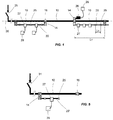
- FIG. 1 shows distribution elements 20 connected by their two ends 22 to bypass devices 14.
- a distribution element 20 is preferably parallel to a transport element 10.
- Figure 5 shows a distribution element 20 'connected by a single its ends 22 to a bypass device 14.
- the element of distribution 20 ' is indifferently either directed parallel to a transport element 10, as shown in FIG. 5, is directed in another direction, for example perpendicular to a transport element 10.
- Each distribution element 20, 20 ′ has, in a distributed manner, at intervals L D which may or may not be regular, for example intervals less than or equal to one meter, a limited number of connection points called branching hatches 25 allowing d '' install junction boxes 27 by plug-in type connections, that is to say a connection authorizing the installation and removal of a junction box 27 without cutting the power supply to the transport system and distribution.
- This type of connection is known and present in many distribution elements, such as prefabricated electrical pipes and its embodiment will not be detailed here.
- the interval L D between two adjacent branch hatches 25 is less than the length L T of the transport elements 10.
- junction boxes 27 are used to power receivers 29 located in downstream. These can thus be distributed advantageously over the entire length of a distribution element 20,20 'for a better distribution of the currents consumed. In addition, it is easy to modify the layout of the receivers 29 connected to the boxes. bypass 27, add or remove certain junction boxes without stopping the operation of other receivers.
- a user when a user wishes to install a receiver 29 of strong power, for example of power greater than or equal to the caliber of an element of distribution, or when it has only one receiver to install over the entire length of a transport element 10, it retains the possibility of connecting this receiver 29 by means a simple junction box 26 connected to a bypass device 14, as indicated in figure 1, this connection being made in a fixed manner and without voltage.
- the safe bypass 26 includes its own usual means of electrical protection against current overloads.
- the elements of transport comprise three transport conductors 11 which have a development at each of their ends 12 to facilitate splinting at the level of a terminal block 15.
- This development generates a distance D between two adjacent conductors 11.
- the value of this distance D is chosen from so as to be substantially equal to the spacing between the conductors 21 of distribution elements 20,20 'in order to simplify the bypass device 14.
- the terminal block comprises in a housing 15 several pairs of plates conductors 17,18, each pair surrounding the stripped ends of a conductor transport 11 and a corresponding distribution conductor 21.
- the insulation between two pairs of conductive plates 17,18 on the one hand and between the plates conductive 17,18 and the housing 15 on the other hand, is provided by an isolation device 19 adequate.
- the first conductive plates 17 and the insulation devices 19 of the terminal block 15 are extended to form a device branch 14 incorporated in the terminal block.
- the first conductive plates 17 provide the electrical connection between a transport conductor 11 and a conductor distribution 21 corresponding.
- the second conductive plates 18 are consisting of two separate half-plates 18a, 18b, the half-plate 18a ensuring the fixing and electrical connection of the transport conductors 11 and the half plate 18b ensuring the fixing and the electrical connection of the distribution conductors 21.
- Such a bypass device 14 thus offers two bypass locations 23 available, each location can accommodate the end 22 of an element of distribution 20.20 'as shown in Figure 3, but also a junction box 26.
- a terminal block 15 can then include two bypass devices 14 located on either side of this longitudinal axis 30 as shown in FIG. 1.
- the whole of the terminal block 15 and the bypass device 14 is tightened by clamping means, consisting for example of several clamping screws 16a, 16b with elastic washers, sufficient to ensure a good electrical connection between the conductors 11, the conductive plates 17, 18a, 18b and the conductors 21.
- clamping means consisting for example of several clamping screws 16a, 16b with elastic washers, sufficient to ensure a good electrical connection between the conductors 11, the conductive plates 17, 18a, 18b and the conductors 21.
- the conductive plates 17, 18a, 18b can advantageously simultaneously realize one or more devices for branch 14 as well as a splicing between two adjacent transport elements 10.
- this embodiment offers less flexibility for setting up branches, since these are either made at the time of splinting between transport elements 10 either require intervention on the transport elements transport 10.
- a terminal block 15 comprises separately a splicing between two transport elements 10 and a or more bypass devices 14.
- the bypass devices 14 are constituted, for example, by diversion hatches according to a known model possibly allowing plug-in type connections.
- Figure 8 shows a example in which a terminal block 15 comprises, in addition to a jointing, a first bypass hatch 14 'directed in one direction and a second hatch bypass 14 "pointing in an opposite direction.
- the bypass doors 14 ', 14" can accommodate 20.20 'distribution elements but also boxes bypass 26.
- the distribution elements 20 can be placed or removed without intervention on the transport elements 10, which simplifies the installation of the system described in the invention.
- this solution allows use standard splices and plug-in type branch connections. It nevertheless requires carrying at the ends of the transport conductors 11 blooming over a greater length. This flourishing of transport conductors 11 generates a distance D between two conductors 11 adjacent. The value of this distance D is chosen so as to be substantially equal to the distance between the conductors 21 of the distribution elements 20,20 ', so that bypass doors 14', 14 "can be used.
- transport elements 10 and distribution elements 20 can, equivalently, include a number of transport conductors 11 and distribution 21 different from three (in particular four conductors for carrying three phases and a neutral).
- the power supply of such a transport and distribution system electrical energy is provided by an external power source (e.g. a transformer) not shown and connected to one end of one of the elements transport 10, with suitable protection means 31.
- an external power source e.g. a transformer
- the total electrical losses P T in the conductors of a pipeline include not only the losses linked to the pure resistance of the conductors, a function of the resistivity of the material used and corrected for the skin effects and proximity effects to which they are subjected. the conductors, but also in particular the losses linked to the variations of the induction B inducing losses by hysteresis in the metallic envelope and losses by eddy currents in the conducting materials. All of these losses vary significantly depending on whether a technology is used with conductors pressed against each other or conductors spaced from each other. It can thus be seen that the resistance, reactance and therefore the impedance of the conductors are much lower in the technology with plated conductors than in the technology with spaced conductors.
- the transport elements 10, the conductors of which are plated generally generate less electrical losses than the distribution elements 20, 20 ′, the conductors of which are spaced apart. The same is true for line voltage drops, especially when the power factor of the installation is low.
- the technology with plated conductors allows better heat dissipation with the outside.
- FIG. 6 a distribution element 20 is connected by its two ends to points A and B of a transport element 10, via two terminal blocks 15 each comprising a bypass device 14.
- the distribution element 20 supplies five receivers 29 assumed identical in this example and each consuming a current I R.
- the five receivers 29 are connected to connection points C, D, E, F and G, corresponding to junction boxes 27 distributed on the element 20.
- FIG. 7 a distribution element 20 'is connected by a only one of its two ends at point A of a transport element 10, via a bypass device 14.
- the distribution element 20 ' supplies three receivers 29 assumed to be identical in this example and each consuming a current I R.
- the three receivers 29 are connected to connection points C, D and E, corresponding to junction boxes 27 distributed on the element 20 '.
- the impedance of a distribution element 20 is much greater than the impedance of a transport element 10 because on the one hand the transport elements 10 are in plated conductor technology and on the other hand the conductor section 21 of a distribution element 20 is less than the cross section of the conductors 11 of a transport element 10.
- the distribution element 20 is therefore traversed mainly by the current corresponding to the receivers 29 which are connected to it.
- this current is distributed on either side of the distribution element 20.
- the current I R consumed by the receiver 29 connected to the point E comes substantially identically from the sections DE and FE.
- the current I DE flowing in the section located between points D and E, is identical to the current I FE , flowing between points F and E, and is equal to: I R / 2.
- the current I CD flowing between points C and D, is identical to the current I GF , flowing between points G and F, and is equal to I R + I DE , ie: 3/2 * I R.
- the current I AC flowing between points A and C, is identical to the current I BG , flowing between points B and G, and is equal to I R + I CD , ie: 5/2 * I R. It can thus be seen that the resulting losses are different in each of the sections of the distribution element 20.
- the sum of the currents consumed by receivers 29 connected to a distribution element 20,20 ′ is much greater than the nominal current I N which would be acceptable over the entire length of this element of distribution 20,20 ', without exceeding the authorized operating temperature limit ⁇ .
- This is obtained on the one hand thanks to the different technologies used for the transport 10 and distribution elements 20, 20 ′, and on the other hand thanks to a limitation of the number and the caliber of the junction boxes 27 and to a distribution of these boxes along a transport element 20,20 '.
- the advantage is to give the user the opportunity to advantageously optimize the size of its distribution elements 20,20 'compared to the currents consumed downstream.
- a nominal current distribution element 20 I N equal to 630A can supply up to five distributed receivers 29 consuming 400A each, if it is connected at its two ends to an element of transport 10.
- a distribution element 20 ′ of nominal current I N equal to 500A and connected only at one end, can supply up to three receivers 29 distributed consuming 250A each.
- junction boxes 27 The limitation of the number of junction boxes 27 is obtained by construction by limiting the number of bypass hatches 25 integrated in a distribution element 20,20 'and limitation of the size of the junction boxes 27 likely to be installed on these bypass hatches 25, is obtained for example using a conventional mechanical coding preventing the connection of housings bypass 27 not allowed.
- the approach to adopt to set up such a system transport and distribution could, for example, be as follows: energy the surface to be fed i.e. install the transport elements 10 along buildings, then according to real needs, install distributed distribution elements 20,20 'and / or distribution boxes 26 only in useful areas of buildings thus optimizing the overall cost of the installation.
- distribution elements 20 connected at their two ends 22 to a bypass device 14, of a length equal to L T according to a preferred embodiment , or equal to a multiple of L T , for example 2 * L T as shown in FIG. 4.
- the distribution elements 20 ′ which are connected only to one end 22, are preferably of a length of the order of L T / 2.
Landscapes
- Connector Housings Or Holding Contact Members (AREA)
- Cable Accessories (AREA)
- Details Of Indoor Wiring (AREA)
- Processing Of Terminals (AREA)
- Emergency Protection Circuit Devices (AREA)
- Connections Effected By Soldering, Adhesion, Or Permanent Deformation (AREA)
- Connections Arranged To Contact A Plurality Of Conductors (AREA)
- Details Of Connecting Devices For Male And Female Coupling (AREA)
Abstract
Description
- la figure 1 représente un exemple de schéma général d'un système conforme à l'invention comportant trois éléments de transport, un coffret de dérivation et deux éléments de distribution raccordés à leurs deux extrémités,
- la figure 2 détaille un mode de réalisation d'un bloc de jonction reliant deux éléments de transport dotés de trois conducteurs,
- la figure 3 montre une vue en coupe du bloc de jonction de la figure 2 selon un axe X-X,
- la figure 4 représente un autre exemple de schéma d'un système conforme à l'invention,
- la figure 5 montre le schéma d'un système comprenant un élément de distribution raccordé par une seule de ses extrémités,
- les figures 6 et 7 illustrent la répartition des courants dans un système conforme à l'invention,
- la figure 8 représente un autre mode de réalisation d'un bloc de jonction.
- le courant nominal IN,
- la résistance globale R des conducteurs,
- la réactance X des conducteurs pour une fréquence d'emploi donnée,
- l'impédance Z = √(R2+X2).
Claims (12)
- Système de transport et de distribution d'énergie électrique comprenant :plusieurs éléments de transport (10) de longueur (LT), possédant chacun plusieurs conducteurs de transport (11) parallèles, isolés et plaqués les uns contre les autres, chaque extrémité de ces éléments de transport (10) présentant un épanouissement (12) des conducteurs de transport (11) pour connecter deux éléments de transport (10) adjacents au moyen d'un bloc de jonction (15),au moins un élément de distribution (20,20') possédant plusieurs conducteurs de distribution (21) parallèles et espacés les uns des autres, dont au moins une des deux extrémités (22) est directement connectée à un élément de transport (10) par un dispositif de dérivation (14) au niveau d'un bloc de jonction (15), sans adjonction de moyens de protection électrique contre les surcharges en courant.
- Système de transport et de distribution d'énergie électrique selon la revendication 1, caractérisé par le fait que les deux extrémités (22) d'un élément de distribution (20) sont directement connectées par des dispositifs de dérivation (14) à des éléments de transport (10), sans adjonction de moyens de protection électrique contre les surcharges en courant.
- Système de transport et de distribution d'énergie électrique selon la revendication 1, caractérisé par le fait que seulement une des deux extrémités (22) d'un élément de distribution (20') est directement connectée par un dispositif de dérivation (14) à un élément de transport (10), sans adjonction de moyens de protection électrique contre les surcharges en courant.
- Système de transport et de distribution d'énergie électrique selon l'une des revendications 1 à 3, caractérisé par le fait que la section des conducteurs de distribution (21) est inférieure à la section des conducteurs de transport (11).
- Système de transport et de distribution d'énergie électrique selon la revendication 4, caractérisé par le fait que un nombre limité de trappes de dérivation (25), espacées par des intervalles (LD), sont aménagées le long des éléments de distribution (20,20'), permettant d'installer des boítiers de dérivation (27) par des connexions de type "plug-in", c'est-à-dire autorisant la pose et la dépose des boítiers de dérivation (27) sans couper l'alimentation électrique du système de transport et de distribution.
- Système de transport et de distribution d'énergie électrique selon la revendication 5, caractérisé par le fait que l'intervalle (LD) entre deux trappes de dérivation (25) est inférieur à la longueur (LT) d'un élément de transport (10).
- Système de transport et de distribution d'énergie électrique selon la revendication 4, caractérisé par le fait que la somme des courants consommés par des récepteurs (29) raccordés à des boítiers de dérivation (27) d'un élément de distribution (20,20') peut être supérieure au courant nominal (IN) parcourant uniformément la longueur d'un élément de distribution (20,20').
- Système de transport et de distribution d'énergie électrique selon l'une des revendications précédentes, caractérisé par le fait qu'un coffret de dérivation (26), muni de ses propres moyens de protection électrique, peut également être connecté à un dispositif de dérivation (14) d'un élément de transport (10).
- Système de transport et de distribution d'énergie électrique selon la revendication 4, caractérisé par le fait que l'épanouissement à chaque extrémité (12) entre les différents conducteurs de transport (11) des éléments de transport (10) est d'une valeur (D) sensiblement identique à l'espacement entre les conducteurs de distribution (21).
- Système de transport et de distribution d'énergie électrique selon la revendication 9, caractérisé par le fait qu'un bloc de jonction (15) comporte des plaques conductrices (17,18a,18b) permettant de réaliser simultanément au moins un dispositif de dérivation (14) ainsi qu'un éclissage entre deux éléments de transport (10) adjacents.
- Système de transport et de distribution d'énergie électrique selon la revendication 10, caractérisé par le fait que chaque dispositif de dérivation (14) dispose de deux emplacements de dérivation (23) disponibles, chaque emplacement pouvant accueillir une extrémité (22) d'un élément de distribution (20,20') ou un coffret de dérivation (26).
- Système de transport et de distribution d'énergie électrique selon l'une des revendications précédentes, caractérisé par le fait qu'un bloc de jonction (15) peut comporter deux dispositifs de dérivation (14).
Applications Claiming Priority (2)
| Application Number | Priority Date | Filing Date | Title |
|---|---|---|---|
| FR0005837A FR2808626B1 (fr) | 2000-05-04 | 2000-05-04 | Systeme de transport et de distribution d'energie electrique |
| FR0005837 | 2000-05-04 |
Publications (2)
| Publication Number | Publication Date |
|---|---|
| EP1152509A1 true EP1152509A1 (fr) | 2001-11-07 |
| EP1152509B1 EP1152509B1 (fr) | 2009-03-04 |
Family
ID=8849986
Family Applications (1)
| Application Number | Title | Priority Date | Filing Date |
|---|---|---|---|
| EP01401046A Expired - Lifetime EP1152509B1 (fr) | 2000-05-04 | 2001-04-25 | Système de transport et de distribution d'énergie électrique |
Country Status (10)
| Country | Link |
|---|---|
| US (1) | US6690097B2 (fr) |
| EP (1) | EP1152509B1 (fr) |
| JP (1) | JP2002078179A (fr) |
| KR (1) | KR100740171B1 (fr) |
| CN (1) | CN1324777C (fr) |
| BR (1) | BRPI0101694B1 (fr) |
| CA (1) | CA2346313C (fr) |
| DE (1) | DE60137816D1 (fr) |
| ES (1) | ES2321277T3 (fr) |
| FR (1) | FR2808626B1 (fr) |
Families Citing this family (7)
| Publication number | Priority date | Publication date | Assignee | Title |
|---|---|---|---|---|
| DE10209771B3 (de) * | 2002-03-05 | 2004-01-29 | Daimlerchrysler Ag | Verteiler für Folienleiter |
| US7388303B2 (en) * | 2003-12-01 | 2008-06-17 | Conocophillips Company | Stand-alone electrical system for large motor loads |
| DE102008062108B4 (de) * | 2008-12-16 | 2026-02-05 | Sew-Eurodrive Gmbh & Co Kg | Umrichtersystem |
| JP5239970B2 (ja) * | 2009-03-17 | 2013-07-17 | 富士通株式会社 | リーク電流算出プログラム、リーク電流算出装置及びリーク電流算出方法 |
| SG11201909902PA (en) * | 2017-05-08 | 2019-11-28 | Abb Schweiz Ag | Multiple fed busbar system |
| CN110247412B (zh) * | 2019-06-14 | 2022-05-24 | 国网浙江综合能源服务有限公司 | 一种记及经济性的储能系统辅助调峰方法 |
| CN117438920B (zh) * | 2023-10-13 | 2024-05-14 | 临沂施乃通电气技术有限公司 | 一种高压环保气体开关柜 |
Citations (3)
| Publication number | Priority date | Publication date | Assignee | Title |
|---|---|---|---|---|
| US3376377A (en) | 1966-08-05 | 1968-04-02 | Gen Electric | Electric power busway with phase collection and branch take-off means |
| US4886468A (en) | 1988-06-08 | 1989-12-12 | General Electric Company | Insulated electrical power distribution busway tabs |
| FR2694845A1 (fr) * | 1992-08-17 | 1994-02-18 | Alsthom Gec | Tableau de distribution électrique d'étage d'immeuble. |
Family Cites Families (22)
| Publication number | Priority date | Publication date | Assignee | Title |
|---|---|---|---|---|
| US538090A (en) * | 1895-04-23 | Electric cut-out | ||
| US3732523A (en) * | 1971-10-12 | 1973-05-08 | Westinghouse Electric Corp | Bus duct system including improved plug-in power take-off means |
| US3742121A (en) * | 1972-02-28 | 1973-06-26 | Square D Co | Tap-off section for a feeder bus duct run |
| US3818417A (en) * | 1972-11-06 | 1974-06-18 | Cutler Hammer Inc | Phase collector assembly for multiple run busway |
| US4009920A (en) * | 1976-04-26 | 1977-03-01 | Cutler-Hammer, Inc. | Power tap-off unit for use at a single-bolt joint in a busway system |
| GB1576617A (en) * | 1976-05-11 | 1980-10-08 | Square D Co | Bus duct system |
| GB1557888A (en) * | 1977-01-19 | 1979-12-12 | Maxam Switchgear Ltd | Electrical distribution systems |
| US4097103A (en) * | 1977-05-18 | 1978-06-27 | General Electric Company | Busway plug assembly |
| CA1251528A (fr) * | 1984-09-13 | 1989-03-21 | Allan E. Slicer | Systeme de distribution electrique a connecteur de canalisations de bus ameliore |
| US4714431A (en) * | 1984-09-13 | 1987-12-22 | Square D Company | Electrical distribution system having an improved plug-in assembly for current tap-off |
| US4739441A (en) * | 1986-08-28 | 1988-04-19 | Westinghouse Canada Inc. | Switchgear assembly |
| US4820178A (en) * | 1988-06-08 | 1989-04-11 | General Electric Company | Outlet box for electric busway system |
| NO932424L (no) * | 1991-03-28 | 1993-07-02 | Dorma Gmbh & Co Kg | Elektrisk energifordelingssystem |
| US5192217A (en) * | 1991-12-31 | 1993-03-09 | Square D Company | Electrical busway distribution system having provisions for preventing unintentional contact with live conductors at tap-off locations |
| US5982645A (en) * | 1992-08-25 | 1999-11-09 | Square D Company | Power conversion and distribution system |
| US5760339A (en) * | 1993-03-25 | 1998-06-02 | Siemens Energy & Automation, Inc. | Busway joint |
| US5415557A (en) * | 1993-08-27 | 1995-05-16 | Square D Company | Busway tap off base assembly for preventing the ingress of dust and liquids |
| US5607317A (en) * | 1994-12-23 | 1997-03-04 | Haworth, Inc. | Electrical powerway for furniture panel |
| US5785542A (en) * | 1996-02-15 | 1998-07-28 | Qbc, Inc. | Electrical distribution system having an improved bus coupler |
| US6142807A (en) * | 1998-10-02 | 2000-11-07 | Siemens Energy & Automation, Inc. | High current and low current electrical busway systems having compatible bus plug |
| US6399882B1 (en) * | 1998-10-02 | 2002-06-04 | Siemens Energy & Automation, Inc. | Dual-hinged door for an electrical power distribution busway |
| US6521837B2 (en) * | 2001-02-23 | 2003-02-18 | Universal Electric Corporation | Electrical busway housing system and connection means therefor |
-
2000
- 2000-05-04 FR FR0005837A patent/FR2808626B1/fr not_active Expired - Lifetime
-
2001
- 2001-04-25 EP EP01401046A patent/EP1152509B1/fr not_active Expired - Lifetime
- 2001-04-25 ES ES01401046T patent/ES2321277T3/es not_active Expired - Lifetime
- 2001-04-25 DE DE60137816T patent/DE60137816D1/de not_active Expired - Lifetime
- 2001-04-30 KR KR1020010023381A patent/KR100740171B1/ko not_active Expired - Fee Related
- 2001-05-01 CA CA2346313A patent/CA2346313C/fr not_active Expired - Fee Related
- 2001-05-02 US US09/846,278 patent/US6690097B2/en not_active Expired - Fee Related
- 2001-05-02 JP JP2001134867A patent/JP2002078179A/ja active Pending
- 2001-05-04 BR BRPI0101694A patent/BRPI0101694B1/pt not_active IP Right Cessation
- 2001-05-04 CN CNB011196890A patent/CN1324777C/zh not_active Expired - Fee Related
Patent Citations (3)
| Publication number | Priority date | Publication date | Assignee | Title |
|---|---|---|---|---|
| US3376377A (en) | 1966-08-05 | 1968-04-02 | Gen Electric | Electric power busway with phase collection and branch take-off means |
| US4886468A (en) | 1988-06-08 | 1989-12-12 | General Electric Company | Insulated electrical power distribution busway tabs |
| FR2694845A1 (fr) * | 1992-08-17 | 1994-02-18 | Alsthom Gec | Tableau de distribution électrique d'étage d'immeuble. |
Also Published As
| Publication number | Publication date |
|---|---|
| JP2002078179A (ja) | 2002-03-15 |
| US6690097B2 (en) | 2004-02-10 |
| US20010039133A1 (en) | 2001-11-08 |
| KR100740171B1 (ko) | 2007-07-16 |
| CN1324777C (zh) | 2007-07-04 |
| FR2808626A1 (fr) | 2001-11-09 |
| BR0101694A (pt) | 2001-12-18 |
| FR2808626B1 (fr) | 2002-06-14 |
| DE60137816D1 (de) | 2009-04-16 |
| CN1323084A (zh) | 2001-11-21 |
| EP1152509B1 (fr) | 2009-03-04 |
| CA2346313A1 (fr) | 2001-11-04 |
| CA2346313C (fr) | 2010-11-23 |
| ES2321277T3 (es) | 2009-06-04 |
| BRPI0101694B1 (pt) | 2016-04-12 |
| KR20010100936A (ko) | 2001-11-14 |
Similar Documents
| Publication | Publication Date | Title |
|---|---|---|
| CA2816654C (fr) | Architecture de redresseur a diodes/thyristors compacte permettant une grande puissance | |
| EP1152509B1 (fr) | Système de transport et de distribution d'énergie électrique | |
| EP2937703B1 (fr) | Dispositif de mesure d'au moins une grandeur électrique d'un courant destiné à circuler dans un appareil électrique, et ensemble comprenant un tel dispositif | |
| EP1107269A1 (fr) | Appareillage de coupure triphasé de forte intensité à deux pôles jumelés par phase, muni de circuits magnétiques de compensation | |
| EP3594699B1 (fr) | Dispositif de protection différentielle | |
| WO2004032300A1 (fr) | Methode de deglaçage de lignes electriques sous charge | |
| EP1684394B1 (fr) | Poste de transformation électrique moyenne tension/basse tension | |
| FR2896335A1 (fr) | Disjoncteur de generateur avec resistance inseree | |
| EP0114539A1 (fr) | Dispositif de connexion à barre omnibus | |
| EP0889329B1 (fr) | Compteur d'électricité muni d'un système de protection contre les surtensions | |
| FR2955198A1 (fr) | Distributeur a coupe-circuit individuel | |
| EP1684395B1 (fr) | Poste de transformation électrique moyenne tension / basse tension | |
| EP0231310B1 (fr) | Dispositif de connexion electrique prefabrique de liaison sur un jeu de barres | |
| EP0901143A1 (fr) | Dispositif d'assemblage et de liaison électrique d'appareils électriques modulaires de puissance tels des disjoncteurs | |
| EP0704874A1 (fr) | Interrupteur différentiel associé à un ou plusieurs éléments de protection de circuit tels des coupe-circuits à fusibles ou disjoncteurs | |
| FR2970127A1 (fr) | Redresseur de forte puissance a faible desequilibre en courant | |
| EP1386380A1 (fr) | Canalisation electrique | |
| EP0561727B1 (fr) | Tableau de comptage de courant triphasé à basse tension | |
| FR3080712A1 (fr) | Systeme de raccordement electrique pour transformateur de tension | |
| EP4371222A1 (fr) | Interconnexions modulaires d'un moteur et d'une electronique de puissance | |
| EP1203272A1 (fr) | Reseau d'alimentation en energie electrique, notamment d'eclairage public | |
| FR2596213A1 (fr) | Tableau electrique de comptage triphase basse tension | |
| EP1790039A2 (fr) | Procede de distribution repartie de l'energie electrique | |
| FR3112037A1 (fr) | Convertisseur de tension DC/DC comprenant un module supérieur et un module inférieur | |
| FR3112042A1 (fr) | Convertisseur de tension AC/DC triphasé comprenant uniquement deux modules de conversion électrique |
Legal Events
| Date | Code | Title | Description |
|---|---|---|---|
| PUAI | Public reference made under article 153(3) epc to a published international application that has entered the european phase |
Free format text: ORIGINAL CODE: 0009012 |
|
| AK | Designated contracting states |
Kind code of ref document: A1 Designated state(s): AT BE CH CY DE DK ES FI FR GB GR IE IT LI LU MC NL PT SE TR Kind code of ref document: A1 Designated state(s): DE ES GB IT SE TR |
|
| AX | Request for extension of the european patent |
Free format text: AL;LT;LV;MK;RO;SI |
|
| 17P | Request for examination filed |
Effective date: 20011127 |
|
| AKX | Designation fees paid |
Free format text: DE ES GB IT SE TR |
|
| RAP1 | Party data changed (applicant data changed or rights of an application transferred) |
Owner name: SCHNEIDER ELECTRONIC INDUSTRIES SAS |
|
| RAP1 | Party data changed (applicant data changed or rights of an application transferred) |
Owner name: SCHNEIDER ELECTRIC INDUSTRIES SAS |
|
| 17Q | First examination report despatched |
Effective date: 20080402 |
|
| GRAP | Despatch of communication of intention to grant a patent |
Free format text: ORIGINAL CODE: EPIDOSNIGR1 |
|
| GRAS | Grant fee paid |
Free format text: ORIGINAL CODE: EPIDOSNIGR3 |
|
| GRAA | (expected) grant |
Free format text: ORIGINAL CODE: 0009210 |
|
| RAP1 | Party data changed (applicant data changed or rights of an application transferred) |
Owner name: SCHNEIDER ELECTRIC INDUSTRIES SAS |
|
| AK | Designated contracting states |
Kind code of ref document: B1 Designated state(s): DE ES GB IT SE TR |
|
| REG | Reference to a national code |
Ref country code: GB Ref legal event code: FG4D Free format text: NOT ENGLISH |
|
| REF | Corresponds to: |
Ref document number: 60137816 Country of ref document: DE Date of ref document: 20090416 Kind code of ref document: P |
|
| REG | Reference to a national code |
Ref country code: ES Ref legal event code: FG2A Ref document number: 2321277 Country of ref document: ES Kind code of ref document: T3 |
|
| REG | Reference to a national code |
Ref country code: SE Ref legal event code: TRGR |
|
| PLBE | No opposition filed within time limit |
Free format text: ORIGINAL CODE: 0009261 |
|
| STAA | Information on the status of an ep patent application or granted ep patent |
Free format text: STATUS: NO OPPOSITION FILED WITHIN TIME LIMIT |
|
| 26N | No opposition filed |
Effective date: 20091207 |
|
| PGFP | Annual fee paid to national office [announced via postgrant information from national office to epo] |
Ref country code: GB Payment date: 20170420 Year of fee payment: 17 Ref country code: DE Payment date: 20170403 Year of fee payment: 17 |
|
| PGFP | Annual fee paid to national office [announced via postgrant information from national office to epo] |
Ref country code: ES Payment date: 20170508 Year of fee payment: 17 Ref country code: IT Payment date: 20170411 Year of fee payment: 17 Ref country code: SE Payment date: 20170502 Year of fee payment: 17 |
|
| PGFP | Annual fee paid to national office [announced via postgrant information from national office to epo] |
Ref country code: TR Payment date: 20170418 Year of fee payment: 17 |
|
| REG | Reference to a national code |
Ref country code: DE Ref legal event code: R084 Ref document number: 60137816 Country of ref document: DE |
|
| REG | Reference to a national code |
Ref country code: DE Ref legal event code: R119 Ref document number: 60137816 Country of ref document: DE |
|
| REG | Reference to a national code |
Ref country code: SE Ref legal event code: EUG |
|
| GBPC | Gb: european patent ceased through non-payment of renewal fee |
Effective date: 20180425 |
|
| PG25 | Lapsed in a contracting state [announced via postgrant information from national office to epo] |
Ref country code: DE Free format text: LAPSE BECAUSE OF NON-PAYMENT OF DUE FEES Effective date: 20181101 Ref country code: SE Free format text: LAPSE BECAUSE OF NON-PAYMENT OF DUE FEES Effective date: 20180426 |
|
| PG25 | Lapsed in a contracting state [announced via postgrant information from national office to epo] |
Ref country code: GB Free format text: LAPSE BECAUSE OF NON-PAYMENT OF DUE FEES Effective date: 20180425 |
|
| PG25 | Lapsed in a contracting state [announced via postgrant information from national office to epo] |
Ref country code: IT Free format text: LAPSE BECAUSE OF NON-PAYMENT OF DUE FEES Effective date: 20180425 |
|
| REG | Reference to a national code |
Ref country code: ES Ref legal event code: FD2A Effective date: 20190912 |
|
| PG25 | Lapsed in a contracting state [announced via postgrant information from national office to epo] |
Ref country code: ES Free format text: LAPSE BECAUSE OF NON-PAYMENT OF DUE FEES Effective date: 20180426 |
|
| PG25 | Lapsed in a contracting state [announced via postgrant information from national office to epo] |
Ref country code: TR Free format text: LAPSE BECAUSE OF NON-PAYMENT OF DUE FEES Effective date: 20180425 |