EP1152501A2 - Insulator displacement stand and automatic insulation displacement machine - Google Patents
Insulator displacement stand and automatic insulation displacement machine Download PDFInfo
- Publication number
- EP1152501A2 EP1152501A2 EP01303844A EP01303844A EP1152501A2 EP 1152501 A2 EP1152501 A2 EP 1152501A2 EP 01303844 A EP01303844 A EP 01303844A EP 01303844 A EP01303844 A EP 01303844A EP 1152501 A2 EP1152501 A2 EP 1152501A2
- Authority
- EP
- European Patent Office
- Prior art keywords
- insulation displacement
- stand
- connector
- electric wire
- connector housing
- Prior art date
- Legal status (The legal status is an assumption and is not a legal conclusion. Google has not performed a legal analysis and makes no representation as to the accuracy of the status listed.)
- Granted
Links
Images










Classifications
-
- H—ELECTRICITY
- H01—ELECTRIC ELEMENTS
- H01B—CABLES; CONDUCTORS; INSULATORS; SELECTION OF MATERIALS FOR THEIR CONDUCTIVE, INSULATING OR DIELECTRIC PROPERTIES
- H01B13/00—Apparatus or processes specially adapted for manufacturing conductors or cables
-
- H—ELECTRICITY
- H01—ELECTRIC ELEMENTS
- H01R—ELECTRICALLY-CONDUCTIVE CONNECTIONS; STRUCTURAL ASSOCIATIONS OF A PLURALITY OF MUTUALLY-INSULATED ELECTRICAL CONNECTING ELEMENTS; COUPLING DEVICES; CURRENT COLLECTORS
- H01R43/00—Apparatus or processes specially adapted for manufacturing, assembling, maintaining, or repairing of line connectors or current collectors or for joining electric conductors
- H01R43/01—Apparatus or processes specially adapted for manufacturing, assembling, maintaining, or repairing of line connectors or current collectors or for joining electric conductors for connecting unstripped conductors to contact members having insulation cutting edges
-
- Y—GENERAL TAGGING OF NEW TECHNOLOGICAL DEVELOPMENTS; GENERAL TAGGING OF CROSS-SECTIONAL TECHNOLOGIES SPANNING OVER SEVERAL SECTIONS OF THE IPC; TECHNICAL SUBJECTS COVERED BY FORMER USPC CROSS-REFERENCE ART COLLECTIONS [XRACs] AND DIGESTS
- Y10—TECHNICAL SUBJECTS COVERED BY FORMER USPC
- Y10T—TECHNICAL SUBJECTS COVERED BY FORMER US CLASSIFICATION
- Y10T29/00—Metal working
- Y10T29/49—Method of mechanical manufacture
- Y10T29/49002—Electrical device making
- Y10T29/49117—Conductor or circuit manufacturing
- Y10T29/49174—Assembling terminal to elongated conductor
-
- Y—GENERAL TAGGING OF NEW TECHNOLOGICAL DEVELOPMENTS; GENERAL TAGGING OF CROSS-SECTIONAL TECHNOLOGIES SPANNING OVER SEVERAL SECTIONS OF THE IPC; TECHNICAL SUBJECTS COVERED BY FORMER USPC CROSS-REFERENCE ART COLLECTIONS [XRACs] AND DIGESTS
- Y10—TECHNICAL SUBJECTS COVERED BY FORMER USPC
- Y10T—TECHNICAL SUBJECTS COVERED BY FORMER US CLASSIFICATION
- Y10T29/00—Metal working
- Y10T29/51—Plural diverse manufacturing apparatus including means for metal shaping or assembling
- Y10T29/5136—Separate tool stations for selective or successive operation on work
- Y10T29/5137—Separate tool stations for selective or successive operation on work including assembling or disassembling station
-
- Y—GENERAL TAGGING OF NEW TECHNOLOGICAL DEVELOPMENTS; GENERAL TAGGING OF CROSS-SECTIONAL TECHNOLOGIES SPANNING OVER SEVERAL SECTIONS OF THE IPC; TECHNICAL SUBJECTS COVERED BY FORMER USPC CROSS-REFERENCE ART COLLECTIONS [XRACs] AND DIGESTS
- Y10—TECHNICAL SUBJECTS COVERED BY FORMER USPC
- Y10T—TECHNICAL SUBJECTS COVERED BY FORMER US CLASSIFICATION
- Y10T29/00—Metal working
- Y10T29/51—Plural diverse manufacturing apparatus including means for metal shaping or assembling
- Y10T29/5136—Separate tool stations for selective or successive operation on work
- Y10T29/5137—Separate tool stations for selective or successive operation on work including assembling or disassembling station
- Y10T29/5138—Separate tool stations for selective or successive operation on work including assembling or disassembling station and means to machine work part to fit cooperating work part
-
- Y—GENERAL TAGGING OF NEW TECHNOLOGICAL DEVELOPMENTS; GENERAL TAGGING OF CROSS-SECTIONAL TECHNOLOGIES SPANNING OVER SEVERAL SECTIONS OF THE IPC; TECHNICAL SUBJECTS COVERED BY FORMER USPC CROSS-REFERENCE ART COLLECTIONS [XRACs] AND DIGESTS
- Y10—TECHNICAL SUBJECTS COVERED BY FORMER USPC
- Y10T—TECHNICAL SUBJECTS COVERED BY FORMER US CLASSIFICATION
- Y10T29/00—Metal working
- Y10T29/51—Plural diverse manufacturing apparatus including means for metal shaping or assembling
- Y10T29/5136—Separate tool stations for selective or successive operation on work
- Y10T29/5137—Separate tool stations for selective or successive operation on work including assembling or disassembling station
- Y10T29/5139—Separate tool stations for selective or successive operation on work including assembling or disassembling station and means to sever work prior to disassembling
- Y10T29/514—Separate tool stations for selective or successive operation on work including assembling or disassembling station and means to sever work prior to disassembling comprising means to strip insulation from wire
-
- Y—GENERAL TAGGING OF NEW TECHNOLOGICAL DEVELOPMENTS; GENERAL TAGGING OF CROSS-SECTIONAL TECHNOLOGIES SPANNING OVER SEVERAL SECTIONS OF THE IPC; TECHNICAL SUBJECTS COVERED BY FORMER USPC CROSS-REFERENCE ART COLLECTIONS [XRACs] AND DIGESTS
- Y10—TECHNICAL SUBJECTS COVERED BY FORMER USPC
- Y10T—TECHNICAL SUBJECTS COVERED BY FORMER US CLASSIFICATION
- Y10T29/00—Metal working
- Y10T29/51—Plural diverse manufacturing apparatus including means for metal shaping or assembling
- Y10T29/5136—Separate tool stations for selective or successive operation on work
- Y10T29/5137—Separate tool stations for selective or successive operation on work including assembling or disassembling station
- Y10T29/5143—Separate tool stations for selective or successive operation on work including assembling or disassembling station and means to machine product
- Y10T29/5145—Separate tool stations for selective or successive operation on work including assembling or disassembling station and means to machine product to sever product to length
-
- Y—GENERAL TAGGING OF NEW TECHNOLOGICAL DEVELOPMENTS; GENERAL TAGGING OF CROSS-SECTIONAL TECHNOLOGIES SPANNING OVER SEVERAL SECTIONS OF THE IPC; TECHNICAL SUBJECTS COVERED BY FORMER USPC CROSS-REFERENCE ART COLLECTIONS [XRACs] AND DIGESTS
- Y10—TECHNICAL SUBJECTS COVERED BY FORMER USPC
- Y10T—TECHNICAL SUBJECTS COVERED BY FORMER US CLASSIFICATION
- Y10T29/00—Metal working
- Y10T29/51—Plural diverse manufacturing apparatus including means for metal shaping or assembling
- Y10T29/5193—Electrical connector or terminal
-
- Y—GENERAL TAGGING OF NEW TECHNOLOGICAL DEVELOPMENTS; GENERAL TAGGING OF CROSS-SECTIONAL TECHNOLOGIES SPANNING OVER SEVERAL SECTIONS OF THE IPC; TECHNICAL SUBJECTS COVERED BY FORMER USPC CROSS-REFERENCE ART COLLECTIONS [XRACs] AND DIGESTS
- Y10—TECHNICAL SUBJECTS COVERED BY FORMER USPC
- Y10T—TECHNICAL SUBJECTS COVERED BY FORMER US CLASSIFICATION
- Y10T29/00—Metal working
- Y10T29/53—Means to assemble or disassemble
- Y10T29/5313—Means to assemble electrical device
- Y10T29/532—Conductor
- Y10T29/53209—Terminal or connector
-
- Y—GENERAL TAGGING OF NEW TECHNOLOGICAL DEVELOPMENTS; GENERAL TAGGING OF CROSS-SECTIONAL TECHNOLOGIES SPANNING OVER SEVERAL SECTIONS OF THE IPC; TECHNICAL SUBJECTS COVERED BY FORMER USPC CROSS-REFERENCE ART COLLECTIONS [XRACs] AND DIGESTS
- Y10—TECHNICAL SUBJECTS COVERED BY FORMER USPC
- Y10T—TECHNICAL SUBJECTS COVERED BY FORMER US CLASSIFICATION
- Y10T29/00—Metal working
- Y10T29/53—Means to assemble or disassemble
- Y10T29/5313—Means to assemble electrical device
- Y10T29/532—Conductor
- Y10T29/53209—Terminal or connector
- Y10T29/53213—Assembled to wire-type conductor
-
- Y—GENERAL TAGGING OF NEW TECHNOLOGICAL DEVELOPMENTS; GENERAL TAGGING OF CROSS-SECTIONAL TECHNOLOGIES SPANNING OVER SEVERAL SECTIONS OF THE IPC; TECHNICAL SUBJECTS COVERED BY FORMER USPC CROSS-REFERENCE ART COLLECTIONS [XRACs] AND DIGESTS
- Y10—TECHNICAL SUBJECTS COVERED BY FORMER USPC
- Y10T—TECHNICAL SUBJECTS COVERED BY FORMER US CLASSIFICATION
- Y10T29/00—Metal working
- Y10T29/53—Means to assemble or disassemble
- Y10T29/5313—Means to assemble electrical device
- Y10T29/532—Conductor
- Y10T29/53209—Terminal or connector
- Y10T29/53213—Assembled to wire-type conductor
- Y10T29/53235—Means to fasten by deformation
Definitions
- the present invention relates to insulation displacement stands.
- the present invention also relates to automatic insulation displacement machines.
- an auto ID machine that is, automatic insulation displacement machine
- an insulation displacement stand for retaining an insulation displacement connector, a movable unit moving back and forth relative to the insulation displacement stand, and a punch attached to the movable unit.
- the insulation displacement connector includes a substantially box-like connector housing, and contacts which are inserted into cavities of the connector housing and which have slots in the upper portions of the contacts for inserting cores of electric wires by insulation displacement. Electric wire insertion holes communicating with the slots of the contacts are opened in the upper surface of the connector housing. The lower surface is used as a pressure-receiving surface for receiving a load by insulation displacement.
- the insulation displacement stand has a horizontal surface for receiving the pressure-receiving surface of the connector housing of the insulation displacement connector, and a vertical surface for receiving the front or rear surface of the connector housing. An insulation displacement load received on the pressure-receiving surface of the connector housing is caught by the horizontal surface. Moreover, the connector housing is positioned in the front-rear direction by being pushed against the vertical surface, for example, by a braking unit provided separately. A pressing surface protruding slightly like a hood from the vertical surface so as to engage with the upper surface of the connector housing is formed in the insulation displacement stand. The pressing surface prevents the connector housing from floating up from the insulation displacement stand. The horizontal surface, the vertical surface and the retaining surface are formed up to the left and right end surfaces of the insulation displacement stand.
- a groove shaped like a substantially sideways U-figure in section is formed by the horizontal surface, the vertical surface and the retaining surface.
- the insulation displacement connector to which the electric wires have been not inserted yet with insulation displacement is inserted from one end of the groove and slid in the right-left direction. Further, the insulation displacement connector is decelerated by the braking unit so as to be positioned in a position for insulation displacement.
- the movable unit is then moved back and forth, the electric wires are connected to the insulation displacement connector with insulation displacement. After the completion of insulation displacement, the insulation displacement connector is pulled in a direction of extending of the electric wires, so that the insulation displacement connector is released from the insulation displacement stand.
- Japanese Patent Application 2000-95953 which has been filed by the Applicant of the present invention discloses an insulation displacement connector which can be connected with electric wires with insulation displacement by means of an auto ID machine even if the insulation displacement connector is provided with a locking portion.
- the insulation displacement connector includes a substantially box-like connector housing and contacts.
- the connector housing has cavities piercing the connector housing, for example, in the front-rear direction, and each of the contacts has a connection portion at one end and slots for connecting cores of electric wires in an upper or lower surface on the other end side with insulation displacement.
- the contacts are inserted into the cavities of the connector housing respectively. Electric wire insertion holes communicating with the slots are opened in the upper or lower surface of the connector housing.
- a surface on a side vertically opposite to the upper or lower surface of the connector housing is used as a pressure-receiving surface for receiving a load by insulation displacement.
- a locking portion to be engaged with a partner connector is provided on the contact connection portion side in the pressure-receiving surface so as to protrude outward.
- a recess portion for making the locking portion escape must be formed in the horizontal surface of the insulation displacement stand.
- the locking portion is hooked by the recess portion so that the insulation displacement connector cannot depart from the insulation displacement stand.
- the present invention was achieved by paying attention to this respect.
- an insulation displacement stand to be attached to an automatic insulation displacement machine for connecting cores of electric wires to an insulation displacement connector with insulation displacement
- the insulation displacement connector including a substantially box-like connector housing and contacts, the connector housing having cavities piercing the connector housing in a front-rear direction, the contacts each having a connection portion at one end and slots for connecting corresponding one of the cores of the electric wires with insulation displacement in an upper or lower surface of the other end side, the contacts being inserted in the cavities of the connector housing, the connector housing having electric wire insertion holes opened in an upper or lower surface of the connector housing so as to communicate with the slots, and a surface vertically opposite to the upper or lower surface to be used as a pressure-receiving surface for receiving an insulation displacement load, a locking portion to be engaged with a partner connector being provided on a contact connection portion side of the pressure-receiving surface so as to protrude outward therefrom, wherein the insulation displacement stand includes: a fixed rack in which a first surface
- Embodiments of the present invention relate to a technical field of an auto ID machine (automatic insulation displacement machine) for pushing electric wires into slots of contacts in an insulation displacement connector and for inserting cores of the electric wires to the slots by insulation displacement.
- an auto ID machine automated insulation displacement machine
- embodiments of the present invention relate to improvements of an insulation displacement stand for retaining the insulation displacement connector.
- Embodiments of the present invention can provide an insulation displacement stand which enables smooth insulation displacement and release of an insulation displacement connector including a locking portion even in the case where the insulation displacement stand is attached to a conventional auto ID machine, and further can provide an auto ID machine having such an insulation displacement stand.
- the first, second, third and fourth surfaces are formed up to at least one end surface of the fixed and movable racks on a side where the insulation displacement connector is charged. Hence, a groove extending in the right-left direction is formed in the insulation displacement stand by the first, second, third and fourth surfaces.
- an insulation displacement load received on the pressure-receiving surface of the connector housing is caught by the first surface.
- the locking portion is made to escape by the difference in level between the first and second surfaces.
- the connector housing is positioned in the front-rear direction by the third surface and the braking unit.
- the fourth surface prevents the connector housing from floating up from the insulation displacement stand.
- the fixed rack and the movable rack are provided so as to be rotatable around a shaft extending in a right-left direction on the third surface.
- the provision of the movable rack which can be made apart from the fixed rack in the heightwise direction can be achieved by a simple structure.
- the automatic insulation displacement machine having the insulation displacement stand as stated in the first or second aspect of the invention is characterized in that the automatic insulation displacement machine includes: an electric wire supplying unit in which consecutive electric wires are reserved; a stationary chuck disposed in front of the electric wire supplying unit for clamping or releasing the electric wires; a movable chuck disposed in front of the stationary chuck for clamping or releasing the electric wires while the movable chuck moves in the front-rear direction; a pressing chuck disposed between the stationary chuck and the movable chuck for clamping or releasing the electric wires; an insulation displacement stand provided on an upper or lower side of the electric wires between the stationary chuck and the pressing chuck; a movable rack driving mechanism for retaining the movable rack in a regular position to bring the movable rack into contact with the insulation displacement connector in a normal state and for rotating the movable rack in a direction to make the movable rack apart from the fixed rack at a time
- the movable chuck moves forward and stops while clamping the end portions of the electric wires drawn out from the electric wire supplying unit through the stationary chuck. Then, the electric wires are strained and clamped by the stationary chuck and the pressing chuck. Then, the electric wires are cut by the cutting mechanism.
- the wire guide is advanced so that the cut end portions of the electric wires are led onto the slots of the insulation displacement connector retained in the insulation displacement stand.
- the punch is advanced so that the cut end portions of the electric wires are pushed into the slots . Then, the wire guide and the punch are retreated.
- the insulation displacement connector to which the electric wires have been connected with insulation displacement is released from the insulation displacement stand.
- the automatic insulation displacement machine having an insulation displacement stand as stated in the first or second aspect of the invention is characterized in that the automatic insulation displacement machine includes: an electric wire supplying unit in which consecutive electric wires are reserved; a stationary chuck disposed in front of the electric wire supplying unit for clamping or releasing the electric wires; a movable chuck disposed in front of the stationary chuck for clamping or releasing the electric wires while the movable chuck moves in the front-rear direction; a pressing chuck disposed between the stationary chuck and the movable chuck for clamping or releasing the electric wires; a first insulation displacement stand constituted by an insulation displacement stand between the stationary chuck and the pressing chuck and having a first surface provided on an upper or lower side of the electric wires so that the first surface faces the electric wires; a second insulation displacement stand constituted by an insulation displacement stand provided in front of the first insulation displacement stand between the stationary chuck and the pressing chuck and having a first surface provided on an upper or
- the movable chuck moves forward and stops while clamping the end portions of the electric wires drawn out from the electric wire supplying unit through the stationary chuck. Then, the electric wires are strained and clamped by the stationary chuck and the pressing chuck. Then, the electric wires are cut by the cutting mechanism.
- the first wire guide is advanced so that the stationary-chuck-side cut end portions of the electric wires are led onto slots of the insulation displacement connector retained in the first insulation displacement stand. Then, the first punch is advanced so that the cut end portions are pushed into the slots.
- the second wire guide is advanced so that the movable-chuck-side cut end portions of the electric wires are led onto slots of the insulation displacement connector retained in the second insulation displacement stand.
- the second punch is advanced so that the cut end portions are pushed into the slots.
- the two wire guides and the two punches are retreated.
- the automatic insulation displacement machine is provided with a split type insulation displacement stand as stated in the first or second aspect of the invention, and further provided with an integral type insulation displacement stand having a first surface for receiving a pressure-receiving surface of a connector housing of an insulation displacement connector stated in the first or second aspect of the invention, a second surface formed with a difference in level in a heightwise direction from the first surface so that the second surface can escape from the locking portion, a third surface for receiving the connection surface having contact connection portions opened in the connector housing, and a fourth surface for receiving the contact connection portion side in a surface having the electric wire insertion holes opened in the connector housing, the first, second, third and fourth surfaces being formed up to opposite side end surfaces, the integral type insulation displacement stand further having a braking unit for pushing the connector housing against the third surface by pressing a surface of the connector housing from which the electric wires are drawn out, characterized in that the automatic insulation displacement machine includes: an electric wire supplying unit in which consecutive electric wires are reserved; a stationary chuck
- the movable chuck moves forward and stops while clamping the end portions of the electric wires drawn out from the electric wire supplying unit through the stationary chuck. Then, the electric wires are strained and clamped by the stationary chuck and the pressing chuck. Then, the electric wires are cut by the cutting mechanism.
- the first wire guide is advanced so that the stationary-chuck-side cut end portions of the electric wires are led onto slots of the insulation displacement connector retained in the first insulation displacement stand. Then, the first punch is advanced so that the cut end portions are pushed into the slots.
- the second wire guide is advanced so that the movable-chuck-side cut end portions of the electric wires are led onto slots of the insulation displacement connector retained in the second insulation displacement stand.
- the second punch is advanced so that the cut end portions are pushed into the slots.
- the two wire guides and the two punches are retreated.
- FIGs. 19 to 21 show the insulation displacement connector 40 including a locking portion according to this embodiment of the present invention.
- the embodiment of the invention shows a six-pole insulation displacement connector 40 by way of example, the number of poles can be selected at option. Electric wires 60 of the number corresponding to the number of poles are connected to the insulation displacement connector 40.
- the insulation displacement connector 40 is connected to a partner connector 50.
- the insulation displacement connector 40 includes a connector housing 41, and male or female contacts 43.
- the connector housing 41 is shaped substantially like a box. Cavities 42 pierce the connector housing 41 in the front-rear direction.
- Each of the contacts 43 has a connection portion 44 at one end and slots 45 in an upper or lower surface of the other end side, so that a core of a corresponding electric wire 60 is connected by the slots 45 with insulation displacement.
- the contacts 43 are inserted into the cavities 42 of the connector housing 41 respectively.
- Electric wire insertion holes 46 communicating with the slots 45 are opened in an upper or lower surface of the connector housing 41. A surface vertically opposite to the surface in which the electric wire insertion holes 46 are opened is used as a pressure-receiving surface 47 for receiving a insulation displacement load.
- a locking portion 48 for engaging the connector 40 with the partner connector 50 is provided on the contact connection portion side of the pressure-receiving surface 47 so as to protrude outward from the surface 47.
- the surface having the electric wire insertion holes 46 opened therein is now called “front surface 41a” and the surface formed to be the pressure-receiving surface 47 and having the locking portion 48 provided thereon is now called “rear surface 41b”.
- the surface of the connector housing 41 having the contact connection portions 44 opened therein is now called “connection surface 41c” and a surface opposite to the surface 41c in the front-rear direction, that is, a surface from which electric wires are drawn out, is now called “wire-out surface 41d”.
- the locking portion 48 has a support portion 48a and an arm 48b.
- the support portion 48a is formed so as to protrude outward.
- the arm 48b extends in the front-rear direction so as to have an intermediate portion connected to the support portion 48a and has an engaging portion 48ba at a front end so as to be engaged with the partner connector 50.
- the locking portion 48 is of a so-called outer lock type.
- the engaging portion 48ba is shaped like a hook bent toward the rear surface 41b of the connector housing 41, and an engaged portion 51 to be hooked by the hook-like engaging portion 47ba is provided on an outer surface of the partner connector 50.
- a gripping portion 48bb is provided at a rear end of the arm 48b.
- the present invention may further include another embodiment of an insulation displacement connector provided with a so-called inner lock type locking portion.
- the engaging portion may be shaped like a hook bent so as to depart from the outer wall portion of the connector housing whereas an engaged portion to be hooked by the hook-like engaging portion may be provided on the outer wall of the partner connector.
- a connector housing portion of the connector housing 41 which receives the slots 45 of the contacts 43 is displaced in the front-rear direction compared with the support portion 48a and arm 48b of the locking portion 48.
- the outer surface of the connector housing portion for receiving the slots 45 can be used as a pressure-receiving surface 47 for receiving a insulation displacement load so that the insulation displacement load is received by the insulation displacement connector 40 steadily, and the electric wires 60 can be connected with insulation displacement by an auto ID machine which will be described later.
- the locking portion 48 makes the insulation displacement connector 40 be hard to be disconnected from the partner connector 50. Hence, occurrence of connection failure can be prevented.
- the connector is used as a insulation displacement connector, both reduction in machining cost and shortening in delivery time of such a connector including an electric wire can be achieved. Moreover, because the fitting length of the contacts 43 can be kept sufficient, connection failure caused by the inclination of the insulation displacement connector 40, or the like, can be prevented even in the case where draw-out force is received from the electric wires 60. Moreover, an intensive clicking sense can be obtained, so that occurrence of connection failure can be prevented in advance when the insulation displacement connector 40 is connected. These effects can be obtained remarkably particularly in a multi-pole connector.
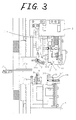
- Figs. 1 to 4 show a first embodiment of an auto ID machine (automatic insulation displacement machine) for connecting cores of electric wires 60 to the aforementioned insulation displacement connector 40 with insulation displacement.
- the reference numeral 1 designates an electric wire supplying unit in which consecutive electric wires 60 are reserved.
- the electric wire supplying unit 1 is constituted by a reel wound with such consecutive electric wires 60.
- a stationary chuck 2 for chucking or releasing the electric wires 60 is disposed in front of the electric wire supplying unit 1.
- the stationary chuck 2 has a pair of clamping members disposed above and under the electric wires 60.
- At least one of the clamping members is moved up or down to make the pair of claming members close to or apart from each other to thereby clamp or release the electric wires 60.
- a movable chuck 3 is disposed in front of the stationary chuck 2 so that the movable chuck 3 chucks or releases the electric wires 60 and is movable in the front-rear direction.
- the movable chuck 3 has a pair of clamping members disposed above and under the electric wires 60. At least one of the clamping members is moved up or down to make the pair of claming members close to or apart from each other to thereby clamp or release the electric wires 60.
- the front-rear direction used herein means a conveniently determined direction in which the left in Fig. 1 means rearward and the right in Fig.
- FIG. 1 means frontward.
- the left in Fig. 4 means the left of the auto ID machine and the right in Fig. 4 means the right of the auto ID machine.
- the upper side in Figs. 1 to 4 means the upper side of the auto ID machine and the lower side in Figs. 1 to 4 means the lower side of the auto ID machine.
- Members such as a pressing chuck, an insulation displacement stand, a wire guide, a punch, a cutting mechanism, a movable stand driving mechanism, a connector charging unit, etc., which will be described later, are disposed between the stationary chuck 2 and the movable chuck 3.
- an upper unit 5 and a lower unit 6 movable up and down are disposed between the stationary chuck 2 and the movable chuck 3 so as to be vertically opposite to each other.
- these members such as a pressing chuck, etc. are provided in the upper and lower units 5 and 6.
- the present invention also includes an embodiment in which these members such as a pressing chuck, etc. are provided individually but without providing the upper and lower units 5 and 6.
- a pressing chuck 4 for clamping or releasing the electric wires 60 is provided between the stationary chuck 2 and the movable chuck 3.
- the pressing chuck 4 has a pair of clamping members disposed above and under the electric wires 60. At least one of the clamping members is moved up or down to make the pair of claming members close to or apart from each other to thereby clamp or release the electric wires 60.
- the pressing chuck 4 has an upper clamping member 4a, and a lower clamping member 4b.
- the upper clamping member 4a is fixed to the upper unit 5.
- the lower clamping member 4b is provided in the lower unit 6 so as to be movable up and down.
- a linking mechanism and an elevating mechanism such as a hydraulic cylinder, a pneumatic cylinder etc. are connected to the lower clamping member 4b so that the lower clamping member 4b can be moved up and down from the lower unit 6 by the elevating mechanism.
- a split type insulation displacement stand is provided between the stationary chuck 2 and the pressing chuck 4 and on an upper or lower side of the electric wires 60.
- two insulation displacement stands are provided.
- a first insulation displacement stand 7 is the split type insulation displacement stand.
- the first insulation displacement stand 7 is provided on an upper or lower side of the electric wires 60 so that a first surface 33 for receiving the pressure-receiving surface 47 of the connector housing 41 faces the electric wires 60.
- a second insulation displacement stand 10 is constituted by an integral type insulation displacement stand.
- the second insulation displacement stand 10 is provided in front of the first insulation displacement stand 7 and on an upper or lower side of the electric wires 60 so that the first surface 33 for receiving the pressure-receiving surface 47 of the connector housing 41 faces the electric wires 60.
- the second insulation displacement stand 10 is reverse to the first insulation displacement stand 7 in the front-rear direction. That is, insulation displacement connectors 40 to be charged in the two insulation displacement stands 7 and 10 respectively are reverse to each other in the front-rear direction.
- the first insulation displacement stand 7 is provided on the upper side of the electric wires 60 and the second insulation displacement stand 10 is provided on the lower side of the electric wires 60.
- the first insulation displacement stand 7 is attached to the upper unit 5 and the second insulation displacement stand 10 is attached to the lower unit 6.
- the two insulation displacement stands 7 and 10 may be disposed separately on the upper and lower sides of the electric wires 60 in the aforementioned manner. Alternatively, the two insulation displacement stands 7 and 10 may be disposed on the upper side of the electric wires 60. Alternatively, the two insulation displacement stands 7 and 10 may be disposed on the lower side of the electric wires 60.
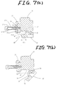
- the first insulation displacement stand 7 constituted by a split type insulation displacement stand will be described with reference to Figs. 5 through 7.
- the first insulation displacement stand 7 has a fixed rack 31, and a movable rack 32.
- the fixed rack 31 has a first surface 33 for receiving the pressure-receiving surface 47 of the connector housing 41, and a second surface 34 for running away from the locking portion 48.
- the first and second surfaces 33 and 34 are formed with a difference in level in the heightwise direction.
- the first and second surfaces 33 and 34 are formed up to at least one of left and right side end surfaces 31a and 31b of the fixed rack 31, that is, up to a side end surface on a side where the insulation displacement connector 40 is charged.
- the first and second surfaces 33 and 34 are formed up to the left and right end surfaces 31a and 31b of the fixed rack 31. Because the connector charging unit 15 for charging the insulation displacement connector 40 in the insulation displacement stand 7 is provided on the left side of the auto ID machine in this embodiment, the operation will go well if the first and second surfaces 33 and 34 are formed up to at least the left end surface 31a of the fixed rack 31.
- the movable rack 32 has a third surface 35 for receiving the connection surface 41c having the contact connection portions 44 opened in the connector housing 41, and a fourth surface 36 for receiving the contact connection portion side in the surface 41a which is a surface having the electric wire insertion holes 46 opened in the connector housing 41.
- the third and fourth surfaces 35 and 36 are formed up to at least one of left and right end surfaces 32a and 32b of the movable rack 32, that is, up to a side end surface on a side where the insulation displacement connector 40 is charged.
- the third and fourth surfaces 35 and 36 are formed up to the left and right end surfaces 32a and 32b of the movable rack 32.
- the connector charging unit 15 for charging the insulation displacement connector 40 in the insulation displacement stand 7 is provided on the left side of the auto ID machine in this embodiment, the operation will go well if the third and fourth surfaces 35 and 36 are formed up to at least the left end surface 32a of the movable rack 32.
- a braking unit 37 is provided in the fixed rack 31 so that the wire-out surface 41d which is a surface of the connector housing 41 and from which the electric wires 60 are drawn out is pressed to thereby press the connector housing 41 against the third surface 35.
- the braking unit 37 has a brake disc 37a, collars 37b, bolts 37c and coiled springs 37d.
- the brake disc 37a is a plate-like member abutting on the front or rear surface of the fixed rack 31 and has an end edge bent like an L-shaped figure in side view to thereby press the wire-out surface 41d of the connector housing 41.
- the collars 37b pierce the brake disc 37a and abut on the front or rear surface of the fixed rack 31.
- Each of the bolts 37c has a neck portion fitted to the collar 37b, and a screw portion piercing the collar 37b and engaged with the front or rear surface of the fixed rack 31 by thread.
- Each of the coiled springs 37d is contracted between the neck portion of the bolt 37c and the brake disc 37a.
- the length of thread engagement of the bolts 37c is changed to change the quantity of contraction of the coiled springs 37d so as to adjust the force of pressing the connector housing 41.
- the collars 37b limit the maximum length of thread engagement of the bolts 37c.
- the insulation displacement connector 40 in which the electric wires 60 are not yet connected is inserted into the insulation displacement stand 7 from one end of the insulation displacement stand 7 and slid in the right-left direction, the insulation displacement connector 40 is decelerated by the braking unit 37 so as to be positioned in a position for insulation displacement.
- the movable rack 32 is provided so that the movable rack 32 can move away from the fixed rack 31 in the heightwise direction.
- the fixed rack 31 and the movable rack 32 are provided so that they can rotate through a shaft 38 extending left and right on the third surface side.
- the second insulation displacement stand 10 constituted by an integral type insulation displacement stand will be described.
- the second insulation displacement stand 10 has a first surface for receiving the pressure-receiving surface 47 of the connector housing 41 of the insulation displacement connector 40, a second surface formed with a difference in level in the heightwise direction from the first surface so that the second surface can escape from the locking portion 48, a third surface for receiving the connection surface 41c having the contact connection portions 44 opened in the connector housing 41, and a fourth surface for receiving the contact connection portion side in the surface 41a which is a surface of the connector housing 41 and from which the electric wire insertion holes 46 are opened.
- the first, second, third and fourth surfaces are formed up to opposite side end surfaces.
- the second insulation displacement stand 10 further has a braking unit 37'.
- the wire-out surface 41d is a surface of the connector housing 41.
- the electric wires 60 are drawn out from the connector housing 41.
- the wire-out surface 41d is pressed by the braking unit 37' to thereby press the connector housing 41 against the third surface.
- the first, second, third and fourth surfaces are formed up to the two side end surfaces, that is, left and right end surfaces of the second insulation displacement stand 10.
- the second insulation displacement stand 10 is equivalent to a first insulation displacement stand 7 except that the fixed rack and the movable rack are integrally provided with each other, that is, except that, in a first insulation displacement stand 7, the movable rack 32 is provided to be able to move away from the fixed rack 31 in the heightwise direction.
- a wire guide and a punch are provided for each of the insulation displacement stands. That is, a first wire guide 8 and a first punch 9 are provided correspondingly with respect to the first insulation displacement stand 7.
- the first wire guide 8 is provided on a side opposite to the first insulation displacement stand 7 with respect to the electric wires 60 so that the first wire guide 8 moves back and forth relative to the first insulation displacement stand 7 to thereby lead end portions of the electric wires 60 onto the slots 45 of the insulation displacement connector 40.
- the first punch 9 is provided on a side opposite to the first insulation displacement stand 7 with respect to the electric wires 60 so that the first punch 9 moves back and forth relative to the first insulation displacement stand 7 to thereby force the end portions of the electric wires 60 into the slots 45 of the insulation displacement connector 40.
- a second wire guide 11 and a second punch 12 are provided correspondingly with respect to the second insulation displacement stand 10.
- the second wire guide 11 is provided on a side opposite to the second insulation displacement stand 10 with respect to the electric wires 60 so that the second wire guide 11 moves back and forth relative to the second insulation displacement stand 10 to thereby lead end portions of the electric wires 60 onto the slots 45 of the insulation displacement connector 40.
- the second punch 12 is provided on a side opposite to the second insulation displacement stand 10 with respect to the electric wires 60 so that the second punch 12 moves back and forth relative to the second insulation displacement stand 10 to thereby force the end portions of the electric wires 60 into the slots 45 of the insulation displacement connector 40.
- the first insulation displacement stand 7 is provided on the upper side of the electric wires 60
- the first wire guide 8 and the first punch 9 are provided on the lower side of the electric wires 60.
- the second insulation displacement stand 10 is provided on the lower side of the electric wires 60
- the second wire guide 11 and the second punch 12 are provided on the upper side of the electric wires 60.
- the wire guides 8 and 11 and the punches 9 and 12 can move back and forth individually relative to the insulation displacement stands 7 and 10 opposite to each other. That is, the first wire guide 8 and the first punch 9 are provided in the lower unit 6 so as to be movable up and down.
- a linking mechanism and an elevating mechanism such as a hydraulic cylinder, a pneumatic cylinder, etc.
- the second wire guide 11 and the second punch 12 are, on the other hand, are provided in the upper unit 5 so as to be movable up and down.
- a linking mechanism and an elevating mechanism such as a hydraulic cylinder, a pneumatic cylinder, etc. are connected to each of the second wire guide 11 and the second punch 12, so that the second wire guide 11 and the second punch 12 can be moved up and down by means of the elevating mechanism.
- Each of the wire guides 8 and 11 has a front end shaped like a comb.
- Cut end portions of the electric wires 60 are clamped and guided between teeth of the comb-like portion.
- Each of the punches 9 and 12 has a front end shaped like a comb. The position of the teeth is shifted left and right so as to be located between teeth of the comb-like portion in corresponding one of the wire guides 8 and 11. The electric wires 60 on the slots 45 of the insulation displacement connector 40 are pressed by the teeth of the comb-like portion respectively.
- a cutting mechanism 13 for cutting the electric wires 60 is provided between the two insulation displacement stands 7 and 10.
- the cutting mechanism 13 has a cutting edge 13a, and a receptacle 13b for receiving the cutting edge 13a. At least one of the cutting edge 13a and the receptacle 13b is moved up or down to make the cutting edge 13a and the receptacle 13b close to or apart from each other so as to cut or release the electric wires 60.
- the cutting edge 13a is provided in the upper unit 5 so as to be movable up and down.
- a linking mechanism and an elevating mechanism such as a hydraulic cylinder, a pneumatic cylinder, etc.
- the receptacle 13b is, on the other hand, provided in the lower unit 6. Conversely, the cutting edge 13a may be provided on the lower side and the receptacle 13b may be provided on the upper side.
- a wire supporter 17 is provided on the rear side of the first insulation displacement stand 7.
- the wire supporter 17 has a plate-like support member 17a, and a push rod 17b for pushing up the support member 17a.
- the support member 17a extends in the front-rear direction while the width of the support member 17 in the right-left direction is made substantially equal to that of the insulation displacement connector 40.
- a rear end of the support member 17a is supported by a shaft extending in the right-left direction, so that, when the push rod 17b extends, the support member 17a is pushed up by the push rod 17b.
- the wire supporter 17 is provided as occasion demands but is not an essential mechanism to the auto ID machine according to the present invention.
- the auto ID machine further has a movable rack driving mechanism 14.
- the movable rack driving mechanism 14 By the movable rack driving mechanism 14, the movable rack 32 of the first insulation displacement stand 7 constituted by a split type insulation displacement stand is retained in a regular position so as to be brought into contact with the insulation displacement connector 40 in a normal state and the movable rack 32 is rotated in a direction to move apart from the fixed rack 31 when insulation displacement is completed.
- the movable rack driving mechanism 14 has an arm 14a and a cylinder 14b.
- the arm 14a is provided at one end of a shaft 38 and extends in the direction of the radius of the shaft 38, while the cylinder 14b has a stretchable rod and is provided in the upper unit 5.
- a front end of the rod of the cylinder 14b is connected to an end portion of the arm 14a, opposite to the shaft 38.
- the movable rack driving mechanism 14 retains the movable rack 32 in a regular position to bring the movable rack 32 into contact with the insulation displacement connector 40 in accordance with the expansion and contraction of the rod of the cylinder 14b, or the movable rack driving mechanism 14 rotates the movable rack 32 in a direction to make the movable rack 32 apart from the fixed rack 31.
- a connector charging unit 15 for charging the insulation displacement connector 40 in each of the insulation displacement stands 7 and 10 is provided on a side of the insulation displacement stand.
- the connector charging unit 15 has a first pusher 15a, a second pusher 15b, and a lifter 15c. Insulation displacement connectors 40 supplied from a parts feeder (not shown) are pushed one by one into the first insulation displacement stand 7 by the first pusher 15a. Insulation displacement connectors 40 supplied from the parts feeder are pushed one by one into the second insulation displacement stand 10 by the second pusher 15b. These pushers 15a and 15b are lifted up and down by the lifter 15c.
- the first, second, third and fourth surfaces 33 to 36 of the first insulation displacement stand 7 are formed up to at least end surfaces 31a and 32a on a side where the insulation displacement connectors 40 are charged, among the left and right end surfaces 31a, 32a, and 31b, 32b of the fixed and movable stands 31 and 32.
- a groove 39 extending in the right-left direction is formed by the first, second, third and fourth surfaces 33 to 36 of the first insulation displacement stand 7 (see Fig. 7(a)).
- the connector charging unit 15 positions the insulation displacement connector 40 in a position for insulation displacement by inserting the insulation displacement connector 40 from one end of the groove 39 and sliding the insulation displacement connector 40 in the right-left direction before the electric wires 60 are connected with insulation displacement.
- any connector charging unit can be used as the connector charging unit according to the present invention so long as the connector charging unit has a function of positioning the insulation displacement connector in a position for insulation displacement by inserting the insulation displacement connector from one end of the groove of the insulation displacement stand and sliding the insulation displacement connector in the right-left direction before the electric wires are connected with insulation displacement.
- the stationary chuck 2, the movable chuck 3, the pressing chuck 4, the upper unit 5, the lower unit 6, the wire guides 8 and 11, the punches 9 and 12, the cutting mechanism 13, the movable rack driving mechanism 14 and the connector. charging unit 15 are controlled by a control unit 16.
- the controlling is performed by the following procedure. While the movable chuck 3 clamps end portions of the electric wires 60 drawn out from the electric wire supplying unit 1 through the stationary chuck 2, the movable chuck 3 moves frontward and stops. While the electric wires 60 are strained and clamped by the stationary chuck 2 and the pressing chuck 4, the electric wires 60 are cut by the cutting mechanism 13.
- the first wire guide 8 is advanced so that the cut end portions of the electric wires 60 on the stationary chuck side are led onto the slots 45 of the insulation displacement connector 40 retained in the first insulation displacement stand 7.
- the first punch 9 is advanced so that the cut end portions are pushed into the slots 45.
- the second wire guide 11 is advanced so that the cut end portions of the electric wires 60 on the movable chuck side are led onto the slots 45 of the insulation displacement connector 40 retained in the second insulation displacement stand 10.
- the second punch 12 is advanced so that the cut end portions are pushed into the slots 45.
- the wire guides 8 and 11 and the punches 9 and 12 are retreated so that the movable rack 32 is made apart from the fixed rack 31 in the first insulation displacement stand 7 by means of the movable rack driving mechanism 14.
- the elevating operations of the first and second insulation displacement stands 7 and 10 are also controlled by the control unit 16.
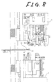
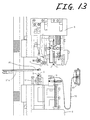
- Figs. 8 and 14 show the state where the respective portions are located in their initial positions. That is, the upper and lower units 5 and 6 are apart from each other, so that the members 4a and 4b of the pressing chuck 4, the first insulation displacement stand 7, the first wire guide 8, the first punch 9, the second insulation displacement stand 10, the second wire guide 11, the second punch 12, the cutting edge 13a and the receptacle 13b of the cutting mechanism 13, etc. provided in these units 5 and 6 are apart from one another to be located in upper and lower portions so as to be in a stand-by state.
- the end portion of the work half done 80 is clamped by the retreated movable chuck 3 and fed forward.
- the electric wires 60 of the work half done 80 are laid front and rear between the upper and lower units 5 and 6.
- the upper unit 5 moves down and the lower unit 6 moves up, so that the two units 5 and 6 approach each other.
- the electric wires 60 are clamped by the pressing chuck 4, so that the electric wires 60 are strained and clamped by the stationary chuck 2 and the pressing chuck 4.
- a template 19 moves down so that the electric wires 60 are retained.
- the template 19 is provided in the upper unit 5 so as to be movable up and down.
- a linking mechanism and an elevating mechanism such as a hydraulic cylinder, a pneumatic cylinder, etc. are connected to the template 19, so that the template 19 can be moved up and down from the upper unit 5 by the elevating mechanism.
- the template 19 may be provided in the lower unit 6 or may be provided separately from the upper and lower units 5 and 6.
- the template 19 is provided as occasion demands but is not an essential mechanism to the auto ID machine according to the present invention.
- the electric wires 60 are cut by the cutting mechanism 13.
- cut end portions of the electric wires 60 are moved in the front-rear direction so as to be positionally fitted to the slots 45 of the insulation displacement connector 40 retained in the insulation displacement stand.
- the stationary-chuck-side cut end portions of the electric wires 60 on the rear side of the cutting edge 13a are slightly displaced rearward by the stationary chuck 2.
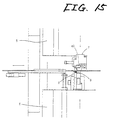
- the first wire guide 8 is advanced so that the cut end portions of the electric wires 60 on the stationary chuck side are led onto the slots 45 of the insulation displacement connector 40 retained in the first insulation displacement stand 7.
- the first punch 9 is advanced so that the cut end portions of the electric wires 60 are pushed into the slots 45 and connected with insulation displacement.
- the support member 17a of the wire supporter 17 is being pushed up by the push rod 17b on the rear side of the first insulation displacement stand 7.
- the second wire guide 11 is advanced so that the cut end portions of the electric wires 60 on the movable chuck side are led onto the slots 45 of the insulation displacement connector 40 retained in the second insulation displacement stand 10.
- the second punch 12 is advanced so that the cut end portions of the electric wires 60 are pushed into the slots 45 and connected with insulation displacement.
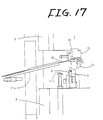
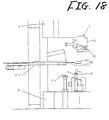
- the insulation displacement connector 40 including the electric wires connected with insulation displacement is released from the first insulation displacement stand 7 constituted by a split type insulation displacement stand. That is, as shown in Fig. 17, when the first wire guide 8 and the first punch 9 are retreated so that the movable rack 32 is moved apart from the fixed rack 31 of the first insulation displacement stand 7 by means of the movable rack driving mechanism 14, the insulation displacement connector 40 to which the cut end portions of the electric wires 60 on the stationary chuck side are connected with insulation displacement is released from the first insulation displacement stand 7. On this occasion, as shown in Figs. 17 and 18, the push rod 17b is retreated on the rear side of the first insulation displacement stand 7.
- the wire supporter 17 is moved down by its own weight, so that the insulation displacement connector 40 unsupported is made to fall down by its own weight.
- the work half done 80 in which the insulation displacement connector 40 is connected with insulation displacement to the one-end portions of the electric wires 60 is put on the wire supporter 17.
- the second wire guide 11 and the second punch 12 are retreated.
- a connector 70 including an electric wire in which insulation displacement connectors 40 are connected to opposite end portions of the electric wires 60 is completed.
- the insulation displacement connectors 40 at the opposite ends of the connector 70 including the electric wire are pushed out toward a side from the second insulation displacement stand 10 and the movable chuck 3 and fed to an next-step apparatus (not shown) such as a current conduction test apparatus provided on the side of the second insulation displacement stand 10 and the movable chuck 3.
- a current conduction test is performed between the insulation displacement connectors 40 at the opposite ends.
- the work of pushing out the insulation displacement connectors 40 from the second insulation displacement stand 10 is performed by the second pusher 15b provided in the connector charging unit 15 described preliminarily.
- the work of pushing out the insulation displacement connectors 40 from the movable chuck 3 is performed by a third pusher (not shown) additionally provided in the connector charging unit 15. Thereafter, the aforementioned operations of the respective portions of the auto ID machine are repeated.
- an insulation displacement load received on the pressure-receiving surface 47 of the connector housing 41 is caught by the first surface 33 of the first insulation displacement stand 7 at the time of insulation displacement.
- the locking portion 48 is allowed to escape by the difference in level between the first and second surfaces 33 and 34.
- the connector housing 41 is positioned in the front-rear direction by the third surface 35 and the braking unit 37.
- the fourth surface 36 prevents the connector housing 41 from floating up from the first insulation displacement stand 7. As shown in Fig.
- the present invention includes all embodiment of the split type insulation displacement stand which is designed to be divided into a fixed rack and a movable rack so that the movable rack can be made apart from the fixed rack in the heightwise direction.
- the present invention includes, for example, an embodiment in which the movable rack is provided so that the movable rack can slide vertically relative to the fixed rack.
- the split type insulation displacement stand 7 can be achieved by a simple structure.
- the present invention includes an embodiment obtained by combination of these embodiments, that is, an embodiment in which the movable rack is provided so as to be vertically slidable relative to the fixed rack and, further, in which the fixed rack and the movable rack are provided so as to be rotatable around the shaft extending in the right-left direction on the third surface side.
- a shaft bearing hole of the fixed rack may be formed to be a long hole so that, when the movable rack is moved apart from the fixed rack in the heightwise direction, the shaft 38 moves in a direction to escape from the insulation displacement connector (frontward in the first mode). If so, the insulation displacement connector can be released more smoothly because the third surface 35 is moved apart from the connection surface 41c of the insulation displacement connector 40 rapidly when the movable rack is moved apart from the fixed rack.
- the first insulation displacement stand 7 is disposed on the upper side of the electric wires 60 and the second insulation displacement stand 10 is disposed on the lower side of the electric wires 60.
- the arrangement of the insulation displacement stands is determined on the basis of the direction in which the insulation displacement connector is connected to the electric wires with insulation displacement. Therefore, the present invention includes all embodiments in which the arrangement of the first insulation displacement stand on the upper side of the electric wires, the arrangement of the first insulation displacement stand on the lower side of the electric wires, the arrangement of the second insulation displacement stand on the upper side of the electric wires and the arrangement of the second insulation displacement stand on the lower side of the electric wires are combined suitably.
- the first and second surfaces 33 and 34 are formed to be the fixed rack 31, and the third and fourth surfaces 35 and 36 are formed to be the movable rack 32.
- the present invention includes a modification in which the first, second and third surfaces are formed to be the fixed rack and the fourth surface is formed to be the movable rack.
- the split type insulation displacement stand according to this modification is a split type insulation displacement stand including a fixed rack, a movable rack, and a braking unit in the following manner.
- a first surface for receiving a pressure-receiving surface of a connector housing, and a second surface to escape from a locking portion are formed in the fixed rack with a difference in level in the heightwise direction.
- a third surface for receiving a connection surface of the connector housing having contact connection portions opened is further formed in the fixed rack.
- the first, second and third surfaces are formed up to at least one side end surface on the side where the insulation displacement connector is charged.
- a fourth surface for receiving the contact connection portion side in a surface of the connector housing having the electric wire insertion holes opened is formed in the movable rack so as to reach at least one side end surface on the side where the insulation displacement connector is charged.
- the braking unit is provided in the fixed rack so that the surface of the connector housing from which the electric wires are drawn out is pressed so as to press the connector housing against the third surface.
- the movable rack is provided so that the movable rack can be made apart from the fixed rack in the heightwise direction.
- a insulation displacement load received on the pressure-receiving surface of the connector housing is caught by the first surface of the split type insulation displacement stand at the time of insulation displacement.
- the locking portion is escaped due to the difference in level between the first and second surfaces.
- the positioning of the connector housing in the front-rear direction is performed by the third surface and the braking unit.
- the fourth surface prevents the connector housing from floating up from the split type insulation displacement stand.
- the split type insulation displacement stand is attached to a conventional auto ID machine, insulation displacement and release of an insulation displacement connector including a locking portion can be performed smoothly.
- the fixed rack and the movable rack may be provided so as to be rotatable around the shaft extending in the right-left direction on the third surface side, or the movable rack may be provided so as to be vertically slidable relative to the fixed rack, or these arrangements may be used in combination, as described above in the aforementioned embodiment for carrying out the invention.
- the first insulation displacement stand is formed to be a split type insulation displacement stand and the second insulation displacement stand more front than the first insulation displacement stand is formed to be an integral type insulation displacement stand.
- the present invention includes, as other embodiments, a second embodiment in which, for example, a first insulation displacement stand is formed to be a split type insulation displacement stand, and a second insulation displacement stand more front than the first insulation displacement stand is also formed to be a split type insulation displacement stand; and a third embodiment in which a insulation displacement stand is provided as a single stand and as a split type insulation displacement stand.
- Fig. 22 shows an auto ID machine according to the second embodiment.
- the second insulation displacement stand 10 is a split type insulation displacement stand having the same configuration as the first insulation displacement stand 7 but is reverse to the first insulation displacement stand 7 in the front-rear direction. That is, insulation displacement connectors 40 to be charged into the two insulation displacement stands 7 and 10 respectively are reverse to each other in the front-rear direction.
- the auto ID machine further has a movable rack driving mechanism 14 for the second insulation displacement stand 10.
- the configuration of the movable rack driving mechanism 14 is the same as that of the movable rack driving mechanism 14 described preliminarily for the first insulation displacement stand 7, except that the cylinder 14b is provided in the lower unit 6 to which the second insulation displacement stand 10 is attached.
- the first and second insulation displacement stands 7 and 10 may be interlocked with each other by one movable rack driving mechanism.
- the configuration of the second embodiment is an auto ID machine having split type insulation displacement stands, which includes: an electric wire supplying unit 1; a stationary chuck 2; a movable chuck 3; a pressing chuck 4; a first insulation displacement stand 7 constituted by a split type insulation displacement stand between the stationary chuck 2 and the pressing chuck 4 and having a first surface 33 provided on an upper or lower side of electric wires 60 so that the first surface 33 faces the electric wires 60; a second insulation displacement stand 10 constituted by a split type insulation displacement stand located in front of the first insulation displacement stand 7 between the stationary chuck 2 and the pressing chuck 4 and having a first surface 33 provided on an upper or lower side of the electric wires 60 so that the first surface 33 faces the electric wires 60; movable rack driving mechanisms 14 for the insulation displacement stands 7 and 10 respectively; a first wire guide 8 for the first insulation displacement stand 7; a first punch 9 for the first insulation displacement stand 7; a second wire guide 11 for the second
- one insulation displacement connector 40 is released from the first insulation displacement stand 7 and, at the same time, another insulation displacement connector 40 is also released from the second insulation displacement stand 10. That is, when the second wire guide 11 and the second punch 12 are retreated, and the movable rack 32 is made apart from the fixed rack 31 in the second insulation displacement stand 10 by the movable rack driving mechanism 14, the insulation displacement connector 40 to which the movable-chuck-side cut end portions of the electric wires 60 are connected with insulation displacement is released from the second insulation displacement stand 10. When, for example, the electric wires 60 are then pulled by the movable chuck 3, the connector 70 including an electric wire with the insulation displacement connectors 40 attached to the opposite end portions of the electric wires 60 is released. Unlike the first embodiment, the second embodiment is adapted to the case where the connector 70 including an electric wire is not automatically fed to the next-step apparatus such as a current conduction test apparatus . Thereafter, the above operations of the respective portions of the auto ID machine are repeated.
- the configuration, operation and effect of the third embodiment are different from those of the first embodiment as follows.
- the first insulation displacement stand 7 is provided but there is no second insulation displacement stand 10.
- the configuration of the third embodiment is an auto ID machine having a split type insulation displacement stand, which includes: an electric wire supplying unit 1; a stationary chuck 2; a movable chuck 3; a pressing chuck 4; a first insulation displacement stand 7 constituted by a split type insulation displacement stand between the stationary chuck 2 and the pressing chuck 4 and provided on an upper or lower side of electric wires 60; a movable rack driving mechanism 14; a first wire guide 8; a first punch 9; a cutting mechanism 13; a connector charging unit 15; and a control unit 16 for controlling the movable chuck 3 to move forward and stop while the movable chuck 3 clamps end portions of the electric wires 60 drawn out from the electric wire supplying unit 1 through the stationary chuck 2, controlling the stationary chuck 2 and the pressing chuck 4 to strain and clamp the electric wires 60, controlling the cutting mechanism 13 to cut the electric wires 60, controlling the first wire guide 8 to advance so as to lead the cut end portions
- the insulation displacement connector 40 is released only from the first insulation displacement stand 7.
- the electric wires 60 as the work half done 80 are cut by the cutting mechanism 13
- a single-side connector including an electric wire in which the insulation displacement connector 40 is connected with insulation displacement only to one end of the electric wires 60 is completed. Thereafter, the above operations of the respective portions of the auto ID machine are repeated.
- the insulation displacement stand is divided into a fixed rack and a movable rack which are provided so that the movable rack can be made apart from the fixed rack in the heightwise direction.
- the provision of the movable rack which is provided so that the movable rack can be made apart from the fixed rack in the heightwise direction can be achieved by a simple structure.
- insulation displacement and release of an insulation displacement connector including a locking portion can be performed automatically and smoothly.
- insulation displacement of insulation displacement connectors including a locking portion to each of opposite ends of electric wires and release of the insulation displacement connectors can be performed automatically and smoothly.
- a series of work of connecting insulation displacement connectors including a locking portion to opposite ends of electric wires and feeding the connectors to a next step such as a current conduction test etc. can be performed automatically and smoothly.
Landscapes
- Engineering & Computer Science (AREA)
- Manufacturing & Machinery (AREA)
- Manufacturing Of Electrical Connectors (AREA)
- Details Of Connecting Devices For Male And Female Coupling (AREA)
- Pressure Welding/Diffusion-Bonding (AREA)
- Multi-Conductor Connections (AREA)
Abstract
Description
Claims (14)
- An insulation displacement stand for an automatic insulation displacement machine for connecting a core of an electric wire to an insulation displacement connector with insulation displacement, the insulation displacement connector including: a connector housing having a cavity piercing the connector housing in a front-rear direction; and a contact having a connection portion at a first end and a slot for connecting the core of the electric wire on one of upper and lower surfaces thereof on a side of a second end, the contact being inserted in the cavity of the connector housing, wherein the connector housing includes an electric wire insertion hole opened on one of upper and lower surfaces of the connector housing so as to communicate with the slot of the contact, a pressure-receiving surface provided vertically opposite to the electric wire insertion hole so as to receive an insulation displacement load, and a locking portion disposed on a side of the first end and protruding outward for engaging with a partner connector, said insulation displacement stand comprising:a first surface for receiving the pressure-receiving surface of the connector housing;a second surface escaping from the locking portion of the connector housing and formed at a level different from one of said first surface in a heightwise direction;a third surface for receiving a connection surface of the connector housing, the connection surface having a hole communicating with the connection portion of the contact;a fourth surface for receiving the one of upper and lower surfaces which the electric wire insertion hole of the connector housing is opened; anda braking unit pressing the connector housing against said third surface by pressing a surface of the connector housing from which the electric wire is drawn out,wherein said first, second, third and fourth surfaces are formed up to at least one side end surface on a side where the insulation displacement connector is charged.
- The insulation displacement stand according to Claim 1, further comprising:a fixed rack on which said first and second surfaces are provided; anda movable rack movably provided so as to be apart from and close to said fixed rack in the heightwise direction, on which said third and fourth surfaces are provided,wherein said braking unit is provided on said fixed rack.
- The insulation displacement stand according to Claim 2, further comprising a shaft extending in a right-left direction with respect to said third surface,
wherein said fixed rack and said movable rack are provided so as to be rotatable around said shaft. - The insulation displacement stand according to Claim 1, wherein said first, second, third and fourth surfaces are provided on one rack and formed up to both side end surfaces.
- An automatic insulation displacement machine for connecting a core of an electric wire to an insulation displacement connector with insulation displacement, the insulation displacement connector including: a connector housing having a cavity piercing the connector housing in a front-rear direction; and a contact having a connection portion at a first end and a slot for connecting the core of the electric wire on one of upper and lower surfaces thereof on a side of a second end, the contact being inserted in the cavity of the connector housing, wherein the connector housing includes an electric wire insertion hole opened on one of upper and lower surfaces of the connector housing so as to communicate with the slot of the contact, a pressure-receiving surface provided vertically opposite to the electric wire insertion hole so as to receive an insulation displacement load, and a locking portion disposed on a side of the first end and protruding outward for engaging with a partner connector, said automatic insulation displacement machine comprising:an electric wire supplying unit consecutively reserving the electric wire;a stationary chuck disposed in front of said electric wire supplying unit for clamping and releasing the electric wire;a movable chuck disposed in front of said stationary chuck for clamping and releasing the electric wire, said movable chuck movable in the front-rear direction;a pressing chuck disposed between said stationary chuck and said movable chuck for clamping and releasing the electric wire;a first insulation displacement stand provided on one of upper and lower sides of the electric wire between said stationary chuck and said pressing chuck, said first insulation displacement stand including:a first surface for receiving the pressure-receiving surface of the connector housing;a second surface escaping from the locking portion of the connector housing and formed at a level different from one of said first surface in a heightwise direction;a third surface for receiving a connection surface of the connector housing, the connection surface having a hole communicating with the connection portion of the contact;a fourth surface for receiving the one of upper and lower surfaces which the electric wire insertion hole of the connector housing is opened; anda braking unit pressing the connector housing against said third surface by pressing a surface of the connector housing from which the electric wire is drawn out,wherein said first, second, third and fourth surfaces of said first insulation displacement stand are formed up to at least one side end surface on a side where the insulation displacement connector is charged;a first wire guide disposed on a side opposite to said first insulation displacement stand with respect to the electric wire and moving up and down relative to said first insulation displacement stand so as to lead an end portion of the electric wire onto the slot of the contact of the insulation displacement connector;a first punch disposed on a side opposite to said first insulation displacement stand with respect to the electric wire and moving up and down relative to said first insulation displacement stand so as to push the end portion of the electric wire onto the slot of the contact of the insulation displacement connector;a cutting mechanism for cutting the electric wire;a connector charging unit for charging the insulation displacement connector in said first insulation displacement stand; anda control unit for controlling said movable chuck to move forward and stop while said movable chuck clamps the end portion of the electric wire drawn out from said electric wire supplying unit through said stationary chuck, controlling said stationary chuck and said pressing chuck to strain and clamp the electric wire, controlling said cutting mechanism to cut the electric wire, controlling said first wire guide to advance so as to lead the cut end portion of the electric wire onto the slot of the insulation displacement connector retained in said first insulation displacement stand, controlling said first punch to advance so as to push the cut end portion of the electric wire into the slot, controlling said first wire guide and said first punch to retreat.
- The automatic insulation displacement machine according to Claim 5, further comprising a movable rack driving mechanism, wherein:
said first insulation displacement stand further including:a fixed rack on which said first and second surfaces of said first insulation displacement stand are provided; anda movable rack movably provided so as to be apart from and close to said fixed rack in the heightwise direction, on which said third and fourth surfaces of said first insulation displacement stand are provided,wherein said braking unit is provided on said fixed rack of said first insulation displacement stand; andsaid movable rack driving mechanism retains said movable rack in a position to bring said movable rack into contact with the insulation displacement connector and rotates said movable rack in a direction to make said movable rack apart from said fixed rack at a time of completion of insulation displacement; andsaid control unit is for controlling said movable rack driving mechanism to make said movable rack apart from said fixed rack in said first insulation displacement stand. - The automatic insulation displacement machine according to Claim 6, whereinsaid first insulation displacement stand further including a first shaft extending in a right-left direction with respect to said third surface of said first insulation displacement stand, andsaid fixed rack and said movable rack are provided so as to be rotatable around said first shaft.
- The automatic insulation displacement machine according to Claim 5, wherein said first, second, third and fourth surfaces of said first insulation displacement stand are provided on one rack and formed up to both side end surfaces.
- The automatic insulation displacement machine according to Claim 5, wherein said first surface of said first insulation displacement stand faces the electric wire.
- The automatic insulation displacement machine according to Claim 5, further comprising:a second insulation displacement stand provided on one of upper and lower sides of the electric wire between said stationary chuck and said pressing chuck, said second insulation displacement stand including:a first surface for receiving the pressure-receiving surface of the connector housing;a second surface escaping from the locking portion of the connector housing and formed at a level different from one of said first surface in a heightwise direction;a third surface for receiving a connection surface of the connector housing, the connection surface having a hole communicating with the connection portion of the contact;a fourth surface for receiving the one of upper and lower surfaces which the electric wire insertion hole of the connector housing is opened; anda braking unit pressing the connector housing against said third surface by pressing a surface of the connector housing from which the electric wire is drawn out,wherein said first, second, third and fourth surfaces are formed up to at least one side end surface on a side where the insulation displacement connector is charged;a second wire guide disposed on a side opposite to said second insulation displacement stand with respect to the electric wire and moving up and down relative to said second insulation displacement stand so as to lead an end portion of the electric wire onto the slot of the contact of the insulation displacement connector;a second punch disposed on a side opposite to said second insulation displacement stand with respect to the electric wire and moving up and down relative to said second insulation displacement stand so as to push the end portion of the electric wire onto the slot of the contact of the insulation displacement connector,wherein said connector charging unit charges the insulation displacement connector in said second insulation displacement stand.
- The automatic insulation displacement machine according to Claim 10, further comprising a movable rack driving mechanism, wherein:said second insulation displacement stand further including:a fixed rack on which said first and second surfaces of said second insulation displacement stand are provided; anda movable rack movably provided so as to be apart from and close to said fixed rack in the heightwise direction, on which said third and fourth surfaces of said second insulation displacement stand are provided,wherein said braking unit is provided on said fixed rack of said second insulation displacement stand; andsaid movable rack driving mechanism retains said movable rack in a position to bring said movable rack into contact with the insulation displacement connector and rotates said movable rack in a direction to make said movable rack apart from said fixed rack at a time of completion of insulation displacement; andsaid control unit is for controlling said movable rack driving mechanism to make said movable rack apart from said fixed rack in said second insulation displacement stand.
- The automatic insulation displacement machine according to Claim 11, whereinsaid second insulation displacement stand further including a second shaft extending in a right-left direction with respect to said third surface of said second insulation displacement stand,wherein said fixed rack and said movable rack are provided so as to be rotatable around said second shaft.
- The automatic insulation displacement machine according to Claim 10, wherein said first, second, third and fourth surfaces of said second insulation displacement stand are provided on one rack and formed up to both side end surfaces .
- The automatic insulation displacement machine according to Claim 10, wherein said first surface of said second insulation displacement stand faces the electric wire.
Applications Claiming Priority (2)
| Application Number | Priority Date | Filing Date | Title |
|---|---|---|---|
| JP2000134055A JP3355174B2 (en) | 2000-05-02 | 2000-05-02 | Split type pressure welding table and automatic pressure welding machine equipped with the same |
| JP2000134055 | 2000-05-02 |
Publications (3)
| Publication Number | Publication Date |
|---|---|
| EP1152501A2 true EP1152501A2 (en) | 2001-11-07 |
| EP1152501A3 EP1152501A3 (en) | 2003-10-01 |
| EP1152501B1 EP1152501B1 (en) | 2005-08-31 |
Family
ID=18642404
Family Applications (1)
| Application Number | Title | Priority Date | Filing Date |
|---|---|---|---|
| EP01303844A Expired - Lifetime EP1152501B1 (en) | 2000-05-02 | 2001-04-27 | Insulator displacement stand and automatic insulation displacement machine |
Country Status (6)
| Country | Link |
|---|---|
| US (1) | US6513215B2 (en) |
| EP (1) | EP1152501B1 (en) |
| JP (1) | JP3355174B2 (en) |
| KR (1) | KR100389744B1 (en) |
| CN (1) | CN1205706C (en) |
| DE (1) | DE60112987T2 (en) |
Cited By (2)
| Publication number | Priority date | Publication date | Assignee | Title |
|---|---|---|---|---|
| CN109462126A (en) * | 2018-11-05 | 2019-03-12 | 珠海格力智能装备有限公司 | Wire separating mechanism |
| CN109648342A (en) * | 2018-12-28 | 2019-04-19 | 王飞 | Movable contact and dynamic the full-automatic of touching bridge rush the match system that is welded |
Families Citing this family (3)
| Publication number | Priority date | Publication date | Assignee | Title |
|---|---|---|---|---|
| US8585430B1 (en) | 2012-04-05 | 2013-11-19 | Google Inc. | Connector with a severing device and wire taps |
| JP2013246915A (en) * | 2012-05-24 | 2013-12-09 | Sumitomo Wiring Syst Ltd | Connector |
| CN107123916A (en) * | 2017-06-08 | 2017-09-01 | 东莞市豪鼎电子有限公司 | Automatic bonding equipment |
Family Cites Families (12)
| Publication number | Priority date | Publication date | Assignee | Title |
|---|---|---|---|---|
| US3965558A (en) * | 1974-08-30 | 1976-06-29 | Trw Inc. | Wire termination apparatus |
| US4370806A (en) * | 1979-02-16 | 1983-02-01 | Molex Incorporated | Electrical harness fabrication apparatus |
| US4351110A (en) * | 1979-10-03 | 1982-09-28 | Amp Incorporated | Apparatus for terminating ribbon cable |
| US4519129A (en) * | 1982-09-09 | 1985-05-28 | Panduit Corp. | Mass termination connector tool assembly |
| US4590650A (en) * | 1984-02-27 | 1986-05-27 | Molex Incorporated | Electrical harness fabrication machine |
| US4918804A (en) * | 1989-03-06 | 1990-04-24 | Molex Incorporated | Modular application tooling for electrical connectors |
| US5197171A (en) * | 1990-03-21 | 1993-03-30 | Amp Incorporated | Cable terminating tool and jig |
| US5187861A (en) * | 1991-09-10 | 1993-02-23 | Panduit Corp. | Wire insertion hand tool with removable bench mounting accessories |
| DE19532130C2 (en) * | 1995-02-02 | 2002-08-29 | Yazaki Corp | Device and method for manufacturing a wire harness |
| JPH08235945A (en) | 1995-02-23 | 1996-09-13 | Nippon Atsuchiyaku Tanshi Seizo Kk | Electric wire guide device for electric harness processing machine |
| US5745975A (en) * | 1996-08-21 | 1998-05-05 | Molex Incorporated | Wire harness termination apparatus for programmable connectors |
| US5797179A (en) * | 1996-10-29 | 1998-08-25 | The Whitaker Corporation | Machine for terminating offset connector |
-
2000
- 2000-05-02 JP JP2000134055A patent/JP3355174B2/en not_active Expired - Fee Related
-
2001
- 2001-04-26 CN CNB011155078A patent/CN1205706C/en not_active Expired - Fee Related
- 2001-04-27 DE DE60112987T patent/DE60112987T2/en not_active Expired - Fee Related
- 2001-04-27 EP EP01303844A patent/EP1152501B1/en not_active Expired - Lifetime
- 2001-04-30 US US09/843,863 patent/US6513215B2/en not_active Expired - Fee Related
- 2001-05-02 KR KR10-2001-0023785A patent/KR100389744B1/en not_active Expired - Fee Related
Cited By (2)
| Publication number | Priority date | Publication date | Assignee | Title |
|---|---|---|---|---|
| CN109462126A (en) * | 2018-11-05 | 2019-03-12 | 珠海格力智能装备有限公司 | Wire separating mechanism |
| CN109648342A (en) * | 2018-12-28 | 2019-04-19 | 王飞 | Movable contact and dynamic the full-automatic of touching bridge rush the match system that is welded |
Also Published As
| Publication number | Publication date |
|---|---|
| US20010037554A1 (en) | 2001-11-08 |
| EP1152501A3 (en) | 2003-10-01 |
| EP1152501B1 (en) | 2005-08-31 |
| KR100389744B1 (en) | 2003-07-02 |
| CN1205706C (en) | 2005-06-08 |
| JP2001319751A (en) | 2001-11-16 |
| DE60112987D1 (en) | 2005-10-06 |
| JP3355174B2 (en) | 2002-12-09 |
| US6513215B2 (en) | 2003-02-04 |
| DE60112987T2 (en) | 2006-07-13 |
| CN1322037A (en) | 2001-11-14 |
| KR20010106206A (en) | 2001-11-29 |
Similar Documents
| Publication | Publication Date | Title |
|---|---|---|
| EP0531912B1 (en) | Electrical harness termination apparatus and method | |
| US3222957A (en) | Wire-stripper mechanism | |
| CN108604785B (en) | Cable processing device | |
| US6990730B2 (en) | System for mounting terminals with electric wires in a connector housing | |
| EP1152501B1 (en) | Insulator displacement stand and automatic insulation displacement machine | |
| US4590650A (en) | Electrical harness fabrication machine | |
| JPH09117114A (en) | Winding method and winding device for rotating electric machine stator | |
| US4765059A (en) | Apparatus for assembling two-part connectors | |
| KR102728300B1 (en) | apparatus for assembling connector | |
| CN118263743A (en) | Automatic three-core wire terminal crimping and thermal shrinkage integrated machine | |
| DE60002927T2 (en) | Improvements in the assembly of connections with electrical conductors in plug housings | |
| CN118676712A (en) | Wire stripping solutions for automated splicing or welding | |
| FI69226B (en) | ANORDNING FOER KOPPLING AV LEDNINGAR | |
| CN111082280B (en) | Conveying, shearing and crimping integrated device for cable end | |
| EP0753911A1 (en) | Wire guiding unit and wire cutting apparatus | |
| EP0601474B1 (en) | Wire-length measuring apparatus | |
| US5144733A (en) | Apparatus for bonding and laying conductors | |
| CN110945725B (en) | Cable processing equipment | |
| EP4443678A1 (en) | Electrical wire stripping solution for automated splicing or welding | |
| CN112706118B (en) | Automatic assembly device | |
| JP3585828B2 (en) | Manual crimping machine | |
| JP3178555B2 (en) | Connector mounting device | |
| JP3403744B2 (en) | Connector mounting device | |
| EP0643455B1 (en) | Apparatus for wiring an electrical connector | |
| JPH07130445A (en) | Connector mounting device |
Legal Events
| Date | Code | Title | Description |
|---|---|---|---|
| PUAI | Public reference made under article 153(3) epc to a published international application that has entered the european phase |
Free format text: ORIGINAL CODE: 0009012 |
|
| AK | Designated contracting states |
Kind code of ref document: A2 Designated state(s): AT BE CH CY DE DK ES FI FR GB GR IE IT LI LU MC NL PT SE TR |
|
| AX | Request for extension of the european patent |
Free format text: AL;LT;LV;MK;RO;SI |
|
| PUAL | Search report despatched |
Free format text: ORIGINAL CODE: 0009013 |
|
| AK | Designated contracting states |
Kind code of ref document: A3 Designated state(s): AT BE CH CY DE DK ES FI FR GB GR IE IT LI LU MC NL PT SE TR |
|
| AX | Request for extension of the european patent |
Extension state: AL LT LV MK RO SI |
|
| 17P | Request for examination filed |
Effective date: 20040302 |
|
| AKX | Designation fees paid |
Designated state(s): DE FR GB IT |
|
| 17Q | First examination report despatched |
Effective date: 20040525 |
|
| GRAP | Despatch of communication of intention to grant a patent |
Free format text: ORIGINAL CODE: EPIDOSNIGR1 |
|
| GRAS | Grant fee paid |
Free format text: ORIGINAL CODE: EPIDOSNIGR3 |
|
| GRAA | (expected) grant |
Free format text: ORIGINAL CODE: 0009210 |
|
| AK | Designated contracting states |
Kind code of ref document: B1 Designated state(s): DE FR GB IT |
|
| REG | Reference to a national code |
Ref country code: GB Ref legal event code: FG4D |
|
| REF | Corresponds to: |
Ref document number: 60112987 Country of ref document: DE Date of ref document: 20051006 Kind code of ref document: P |
|
| PGFP | Annual fee paid to national office [announced via postgrant information from national office to epo] |
Ref country code: FR Payment date: 20060315 Year of fee payment: 6 |
|
| ET | Fr: translation filed | ||
| PGFP | Annual fee paid to national office [announced via postgrant information from national office to epo] |
Ref country code: IT Payment date: 20060430 Year of fee payment: 6 |
|
| PLBE | No opposition filed within time limit |
Free format text: ORIGINAL CODE: 0009261 |
|
| STAA | Information on the status of an ep patent application or granted ep patent |
Free format text: STATUS: NO OPPOSITION FILED WITHIN TIME LIMIT |
|
| 26N | No opposition filed |
Effective date: 20060601 |
|
| PG25 | Lapsed in a contracting state [announced via postgrant information from national office to epo] |
Ref country code: FR Free format text: LAPSE BECAUSE OF NON-PAYMENT OF DUE FEES Effective date: 20070430 |
|
| PGFP | Annual fee paid to national office [announced via postgrant information from national office to epo] |
Ref country code: DE Payment date: 20080502 Year of fee payment: 8 |
|
| PG25 | Lapsed in a contracting state [announced via postgrant information from national office to epo] |
Ref country code: IT Free format text: LAPSE BECAUSE OF NON-PAYMENT OF DUE FEES Effective date: 20070427 |
|
| PG25 | Lapsed in a contracting state [announced via postgrant information from national office to epo] |
Ref country code: DE Free format text: LAPSE BECAUSE OF NON-PAYMENT OF DUE FEES Effective date: 20091103 |
|
| PGFP | Annual fee paid to national office [announced via postgrant information from national office to epo] |
Ref country code: GB Payment date: 20110427 Year of fee payment: 11 |
|
| GBPC | Gb: european patent ceased through non-payment of renewal fee |
Effective date: 20120427 |
|
| PG25 | Lapsed in a contracting state [announced via postgrant information from national office to epo] |
Ref country code: GB Free format text: LAPSE BECAUSE OF NON-PAYMENT OF DUE FEES Effective date: 20120427 |