EP1152416A2 - Disk drive - Google Patents
Disk drive Download PDFInfo
- Publication number
- EP1152416A2 EP1152416A2 EP01109587A EP01109587A EP1152416A2 EP 1152416 A2 EP1152416 A2 EP 1152416A2 EP 01109587 A EP01109587 A EP 01109587A EP 01109587 A EP01109587 A EP 01109587A EP 1152416 A2 EP1152416 A2 EP 1152416A2
- Authority
- EP
- European Patent Office
- Prior art keywords
- voltage
- head
- disk drive
- drive apparatus
- disk
- Prior art date
- Legal status (The legal status is an assumption and is not a legal conclusion. Google has not performed a legal analysis and makes no representation as to the accuracy of the status listed.)
- Granted
Links
- 230000007423 decrease Effects 0.000 abstract description 6
- 238000000034 method Methods 0.000 description 6
- 230000006870 function Effects 0.000 description 5
- 239000007858 starting material Substances 0.000 description 5
- 238000010586 diagram Methods 0.000 description 3
- 238000012544 monitoring process Methods 0.000 description 2
- 238000004891 communication Methods 0.000 description 1
- 230000003247 decreasing effect Effects 0.000 description 1
- 230000002708 enhancing effect Effects 0.000 description 1
- 239000004973 liquid crystal related substance Substances 0.000 description 1
- 230000002040 relaxant effect Effects 0.000 description 1
- 239000000725 suspension Substances 0.000 description 1
- 238000011144 upstream manufacturing Methods 0.000 description 1
Images




Classifications
-
- G—PHYSICS
- G11—INFORMATION STORAGE
- G11B—INFORMATION STORAGE BASED ON RELATIVE MOVEMENT BETWEEN RECORD CARRIER AND TRANSDUCER
- G11B19/00—Driving, starting, stopping record carriers not specifically of filamentary or web form, or of supports therefor; Control thereof; Control of operating function ; Driving both disc and head
- G11B19/02—Control of operating function, e.g. switching from recording to reproducing
- G11B19/04—Arrangements for preventing, inhibiting, or warning against double recording on the same blank or against other recording or reproducing malfunctions
-
- G—PHYSICS
- G11—INFORMATION STORAGE
- G11B—INFORMATION STORAGE BASED ON RELATIVE MOVEMENT BETWEEN RECORD CARRIER AND TRANSDUCER
- G11B21/00—Head arrangements not specific to the method of recording or reproducing
- G11B21/02—Driving or moving of heads
- G11B21/12—Raising and lowering; Back-spacing or forward-spacing along track; Returning to starting position otherwise than during transducing operation
-
- G—PHYSICS
- G11—INFORMATION STORAGE
- G11B—INFORMATION STORAGE BASED ON RELATIVE MOVEMENT BETWEEN RECORD CARRIER AND TRANSDUCER
- G11B21/00—Head arrangements not specific to the method of recording or reproducing
- G11B21/16—Supporting the heads; Supporting the sockets for plug-in heads
- G11B21/22—Supporting the heads; Supporting the sockets for plug-in heads while the head is out of operative position
Definitions
- the present invention relates to a disk drive for playing or driving an information-recording disk, such as a magnetic disk.
- HDDs hard disk drives
- the HDDs are capable of storing video and music contents in quantity and hence the products utilizing them are placed into marketing one after another. It is expected to mount them upon the car audio products.
- the DVDs nowadays are in the mainstream in the field of car navigation systems. It is however expected of shift from now on into HDDs.
- the basic structure of an HDD is shown in Fig. 1.
- the HDD adopts a ramp-loading scheme that a float head slider 51 arranged at a tip of the actuator 54 is mechanically floated from a surface of the magnetic disk.
- the magnetic head 51 on the actuator 54 is arranged for radial movement (shown by arrows) of the magnetic disk 53 and positioned by a voice coil motor (VCM) 160.
- VCM voice coil motor
- the magnetic head 51 is urged onto the surface of the magnetic disk 53 by an elastic force of the suspension 57, it is controlled to have a distance of several tens of ⁇ m to the disk surface of the magnetic disk 53 due to aerodynamic floating force acting upon the magnetic head 51 by a rotation of the magnetic disk 53.
- the magnetic head 51 not in operation is positioned in a retracted position where it is on a taper 56 of a ramp 55 formed at one end of the housing frame 50.
- Fig. 2 shows a positional relationship in a sectional view between the magnetic head 51 and the ramp 55.
- the ramp 55 positioned close to the outer periphery of the magnetic disk 53 has a taper 56 given gradually higher than a surface of the magnetic disk 53 in a direction toward a radial outward of the disk.
- the magnetic head 51 positions at a play position (in a position a) with a proper spacing to a main surface of the magnetic disk 53. In out of operation (or in unload), it gets over the taper 56 as shown by the arrow A to reach a retract position, or home position b, for waiting.
- the emergency unload function refers to a function that, where power voltage to the motor for driving the spindle 52 and magnetic head 51 is greatly decreased, the head 51 is forcibly moved to the retract position, in order to prevent a magnetic disk 53 from being damaged by the magnetic head 53.
- a power supply is required for carrying out the emergency unload.
- the emergency unloading is performed by the use of a reverse electromotive force, i.e. no-load electromotive force, caused by the inertial rotation of the spindle motor 52.
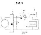
- Fig. 3 shows an example of a power supply circuit in an engine-driven vehicle. That is, an alternator G is driven by an engine, not shown. The alternating current supplied from the alternator G is rectified and smoothed by a rectifier D and then supplied to a battery B. The battery voltage Vb on the battery B is supplied to a movable contact m of an engine-key switch SW. The engine key switch SW has fixed terminals ACC, ON and ST. The battery voltage Vb passed through the terminal ACC is supplied as ACC power to a light load such as an audio unit. The battery voltage Vb passed through the terminal ON is supplied as ON power to a heavy load HL such as a power window actuator.
- the battery voltage Vb passed through the terminal ST is supplied as an MST voltage to a starter motor (not shown), to rotate the starter motor and start up the engine.
- the battery voltage Vb is supplied as a backup power to a light load LL through a line BU.
- Figs. 4A and 4B show voltage on the power supply lines how the voltages of BACKUP and ACC change at the engine start.
- Fig. 4A depicts a manner of change in power voltage of the backup power supply while
- Fig. 4B depicts a manner of change in the ACC power supply.
- the timings (I), (II), (III) and (IV) respectively correspond to the key switch positions of the engine key.
- (I) represents a case the engine key is positioned at an ACC position to supply power to a light load such as an audio unit, (II) a case at an ON position to supply power to a heavy load, for example, of the power window actuator or the like, (III) a case at an ST position to supply power to the starter motor and (IV) a case the engine key is returned to the ON position .
- the HDD is mounted on an engine-driven vehicle
- the emergency unload is to forcibly move the head by utilizing the reverse electromotive force of the spindle motor as described above
- there are increased occasions in the vehicular-mounted disk drive that the float head slider 51 collide with the taper 56 on the ramp 55 in the course of reaching the wait position b on the ramp 55 as compared to the case where the disk drive is mounted on a home-use device such as a home-use personal computer.
- the vehicular-mounted HDD requires increased endurance for the magnetic head 51. This circumstance is commonly problematic for the disk drive apparatuses for use with unstable power voltage.
- the present invention has been made in view of the above circumstance, and it is an object of the present invention to provide a disk drive apparatus capable of avoiding the decrease in endurance even if it is used under an unstable power supply.
- the present invention provides a disk drive apparatus for controlling, under supply of a predetermined rating voltage of power voltage, a head drive section to position a head in a radial direction of an information recording disk and carry out write and/or read operation of information while rotatively driving the information recording disk by a rotation drive motor
- the disk drive apparatus including: a forcible restoring section for controlling the head drive section to forcibly bring the head to a retract position by no-load electromotive force due to the rotation drive motor when the power voltage goes below a first voltage level; and a normal restoring section for controlling the head drive section to move the head toward the retract position on the basis of the power voltage while the power voltage is smaller than the rating voltage but greater than the first voltage level.
- Fig. 5 shows a car navigation system including an HDD according to the present invention.
- the HDD is used as a map information memory section for a car navigation system.
- the car navigation system as illustrated has a host CPU 11 serving as a control core and configured with a ROM 12, a RAM 13, a timer LSI (14), an HDD 15, a sensor section 16, a GPS receiver section 17, an interface 18, an input device 19, a display 20, a display control section 21, a display memory 22. a sound processing circuit 23, a speaker 24, a power supply circuit 25, a hard disk controller (HDC) 26 and a backup RAM 27.
- HDC hard disk controller
- the host CPU 11 administers overall control of navigation including search for destination and route guide in cooperation with the display control section 21 depending upon a program stored in the ROM 12 and RAM 13, according to an instruction given from a user through the input device 19.
- utilized is geographical information available, through the sensor section 16 and GPS receiver section 17.
- the timer LSI (14) has a time count value set programmable by the host CPU 11 and issues an interrupt at a time-up, thereby to initiate an interrupt process routine.
- the HDC 26 administers format control of a magnetic disk loaded on the HDD 15 and, further, has functions as a host interface and an HDD interface.
- the sensor section 16 refers to sensors needed in self-controlled traveling as a car navigation system and, for example, a vehicular speed sensor, a gyro-sensor or the like connected to a system bus 10 through the interface 18.
- the interface 18 is supplied also with an output of the GPS receiver section 17 to provide hybrid-traveling control based on GPS positioning and self-controlled traveling.
- the display 20 is configured, for example, with a liquid crystal monitor to read in and display, through the display control section 21, a process content of geographical information or the like written in the display memory 22 by the host CPU 11.
- the input device 19 is a remote control or console to be used as a GUI used to input commands or make communication with the navigation system through the display 20.
- the sound processing circuit 23 functions to generate a voice guide or as a GUI to dialogue with the navigation system by voice input.
- the voice guide is outputted through the speaker 24.
- the reference 25 is a vehicular power supply circuit and includes a backup power supply line and an ACC power supply line, as described above.
- Fig. 6 shows a voltage monitor device 30 for detecting voltage values of the backup power and the ACC power of the HDD 15 and vehicular power supply circuit 25.
- the vehicular power supply circuit 25 comprises a backup power source line 251 and an ACC power source line 252.
- the voltage monitor device 30 is formed with a voltage comparator circuit 301 and a threshold setting circuit 302.
- the voltage monitor circuit 30 monitors respective voltage values of the powers supplied through the power supply lines 251 and 252 from the backup power supply and the ACC power supply.
- the threshold setting circuit 302 is set with a threshold value to detect voltage drop, the value of which is to be informed to the voltage comparator circuit 301.
- the HDD 15 is configured by an CPU 152 built within the HDD as a core, a host interface circuit 151, a program memory 153, a data memory 154, an HDD interface circuit 155, an R/W (read/write) circuit 156, a head-drive control circuit 157, a spindle-motor control circuit 158, a magnetic head 51, a voice coil motor (VCM) 160 and a spindle motor 161.
- an CPU 152 built within the HDD as a core, a host interface circuit 151, a program memory 153, a data memory 154, an HDD interface circuit 155, an R/W (read/write) circuit 156, a head-drive control circuit 157, a spindle-motor control circuit 158, a magnetic head 51, a voice coil motor (VCM) 160 and a spindle motor 161.
- VCM voice coil motor
- the host interface 151, the HDD-built CPU 152, the program memory 153, the data memory 154 and the HDD interface circuit 155 are commonly connected to an HDD system bus 150.
- the HDD-built CPU 152 receives a command (Seek, Read/Write, etc.) through the host interface circuit 151 from the CPU 11 shown in Fig. 5, to control the R/W circuit 156, head-drive control circuit 157 and spindle-motor control circuit 158 through the HDD interface circuit 155 according to a program stored in the program memory 153.
- the data to be read from and written to the magnetic disk 53 through the magnetic head 51 is under control of the R/W circuit 156.
- the drive to the VCM 160 is under control of the head-drive control circuit 157.
- the rotation drive to the spindle motor 161 is under control of the spindle-motor control circuit 158.
- a power switch exclusive for the HDD can be provided on the lines 251, 252 at an upstream of the monitor points 251a, 252a for the voltage monitor circuit 30, for example, at a position surrounded by a broken line B.
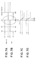
- Fig. 7A and Fig. 7B are timing charts showing voltage waveforms of the respective power supplies at a startup of the vehicle engine.
- Fig. 7A shows a voltage waveform of the backup power supplied through the power supply line 251
- Fig. 7B shows a voltage waveform of the ACC power supplied through the ACC power supply line 252.
- the voltage waveforms of the both power voltages are similar to the voltage waveforms shown in Figs. 4A and 4B, and detailed explanations are herein omitted.
- the present invention controls such that a voltage value at immediately before starting emergency unload (time A) is detected to perform normal unload operation upon detecting the voltage value. That is, where the normal power voltage or the ACC power voltage is given at 12V, the voltage value for starting normal unload is 9V and the voltage value for starting emergency unload is 4.5V, the voltage value on the backup power supply or the ACC power supply is monitored.
- the voltage value becomes 9V time A
- normal unload is started to start moving the head to a retract-position direction.
- the circuits such as the host CPU 11 and the HDD-built CPU 152 are reset which results in the emergency unload.
- Fig. 8A shows a routine carried out by the host CPU 11 and Fig. 8B a process by the HDD-built CPU 152.
- the host CPU 11 monitors whether the power voltage on the ACC power line varying interacting with a key switch is ON, or 12V, or not (step S41).
- the ACC power is ON, power is supplied to the overall navigation system of fig. 5, driving a spindle motor 161 of the HDD 15 to rotate.
- the voltage value ⁇ of the backup power 251 is monitored (step S42).
- the above steps S41 and S42 are executed by monitoring an output signal from a voltage-value monitor circuit 301 shown in Fig. 6.
- step S43 the host CPU 11 instructs head normal unload to a head-drive control circuit 157 and the HDD-built CPU 152 instructs normal unload to the head drive circuit 157 (step S43).
- the system entirety including the host CPU 11 automatically turns into a reset state, the control on the magnetic head 51 by the head drive circuit 157 is suspended.
- a relay RL is restored to supply the reverse electromotive force of the spindle motor 161 to the VCM 160 through a break contact of a contact rl, effecting the emergency unload operation (step S44).
- the host CPU 11 monitors a voltage waveform of the backup power after tuning on the HDD power switch.
- a normal-unload instruction is issued to the CPU 152 of the HDD controller 26.
- the HDD-built CPU 152 carries out the following process according to a control instruction by the host CPU 11.
- the HDD-built CPU 152 decodes the instruction. If, at this moment, the HDD is within either the write or read operation mode, the CPU 152 causes to move the magnetic head 51 toward the outer periphery (step S52). Then, monitor is made on whether the magnetic head 51 has reached the outermost periphery or not (step S53). When reaching the outermost periphery is confirmed, a process is made to cause the magnetic head 51 to climb the ramp 55 (step S54).
- the magnetic head 51 is moved toward the outermost periphery by the reverse electromotive force of the spindle motor 161 so that is climbs the ramp 55.
- the emergency unload is effected via the normal unload when the backup voltage drops under the state where the ACC power is supplied.
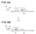
- the magnetic head 51 when the voltage value ⁇ of the backup power is a steady voltage of 12V is assumed in a position hatched in Fig. 9A. If in this position the backup power voltage value ⁇ goes below 9V, the normal unload is initiated. This moves the magnetic head 51 in a direction shown by the arrow in Fig. 9A. The movement of the magnetic head 51 is continued until the backup power voltage becomes 4.5V. In Fig. 9A, the backup power voltage is assumed to drop to 4.5V where the magnetic head 51 comes to a dot-lined position.
- the emergency unload is started (Fig. 9B).
- the magnetic head 51 collides with a taper 56 of the ramp 55, an impact degree of which is in proportion to a distance between the magnetic head 51 and the ramp 55, i.e. the impact degree is greater as the magnetic head 51 and the ramp 55 are distant farer. Consequently, where the normal unload is made immediately before the emergency unload, the magnetic head 51 is moved even a little toward the outer periphery thus relaxing the impact of collision between the magnetic head 51 and the ramp 55.
- the present invention moves the head in the direction toward the outer periphery when power voltage drop is detected in a range of no occurrence of emergency unload. Even when thereafter emergency unload is effected, the impact caused upon collision of the head with the taper of the ramp is relaxed thus prevent the lifetime of the HDD to be shortened.
- the foregoing normal-unload operation by the HDD device is to be effected not only at an engine startup but also in an event of power-voltage drop after starting the engine.
- detected is a voltage immediately before occurrence of the emergency unload caused by an abrupt decrease in the power voltage.
- the magnetic head is first moved in a direction toward an outer periphery, and thereafter the emergency unload is carried out. This can relax the impact caused upon collision of the magnetic head with a taper of a ramp, thus enhancing endurance and improving reliability.
Landscapes
- Rotational Drive Of Disk (AREA)
- Power Sources (AREA)
- Moving Of Heads (AREA)
- Moving Of Head For Track Selection And Changing (AREA)
- Supporting Of Heads In Record-Carrier Devices (AREA)
Abstract

Description
Claims (7)
- A disk drive apparatus for controlling, under supply of a predetermined rating voltage of power voltage, a head drive section to position a head in a radial direction of an information recording disk and carry out write and/or read operation of information while rotatively driving the information recording disk by a rotation drive motor, the disk drive apparatus including:a forcible restoring section for controlling the head drive section to forcibly bring said head to a retract position when said power voltage goes below a first voltage level; anda normal restoring section for controlling said head drive section to move said head toward said retract position on the basis of said power voltage while said power voltage is smaller than said rating voltage but greater than said first voltage level.
- A disk drive apparatus according to claim 1, wherein said information recording disk is a magnetic disk.
- A disk drive apparatus according to claim 2, wherein said head is a magnetic head, and said retract position has a ramp provided for said magnetic head to run thereon.
- A disk drive apparatus according to claim 1, wherein said power voltage is a voltage based on a battery voltage of a vehicle-mounted battery to be charged by a generator operating responsive to rotation of a vehicle-mounted engine.
- A disk drive apparatus according to claim 4, wherein said forcible restoring section and said normal restoring section are operated by a microprocessor operating on said power voltage.
- A vehicle-mounted navigation system including a disk drive apparatus according to claim 4.
- A disk drive apparatus according to claim 6, wherein monitor is made on only a battery voltage to said disk drive apparatus to detect variation in said power voltage.
Applications Claiming Priority (2)
| Application Number | Priority Date | Filing Date | Title |
|---|---|---|---|
| JP2000123263 | 2000-04-24 | ||
| JP2000123263A JP3937064B2 (en) | 2000-04-24 | 2000-04-24 | Recording / playback device |
Publications (3)
| Publication Number | Publication Date |
|---|---|
| EP1152416A2 true EP1152416A2 (en) | 2001-11-07 |
| EP1152416A3 EP1152416A3 (en) | 2002-01-23 |
| EP1152416B1 EP1152416B1 (en) | 2006-06-07 |
Family
ID=18633595
Family Applications (1)
| Application Number | Title | Priority Date | Filing Date |
|---|---|---|---|
| EP01109587A Expired - Lifetime EP1152416B1 (en) | 2000-04-24 | 2001-04-18 | Disk drive |
Country Status (5)
| Country | Link |
|---|---|
| US (1) | US7075745B2 (en) |
| EP (1) | EP1152416B1 (en) |
| JP (1) | JP3937064B2 (en) |
| CN (1) | CN1337674A (en) |
| DE (1) | DE60120272T2 (en) |
Families Citing this family (13)
| Publication number | Priority date | Publication date | Assignee | Title |
|---|---|---|---|---|
| JP3492629B2 (en) | 2000-12-11 | 2004-02-03 | Necパーソナルプロダクツ株式会社 | Magnetic recording / reproducing device |
| JP2005346741A (en) * | 2004-05-31 | 2005-12-15 | Toshiba Corp | Disk storage device and emergency head retraction control circuit applied to the same |
| SG126010A1 (en) * | 2005-03-31 | 2006-10-30 | Seagate Technology Llc | Ramp unload in disc drives |
| JP4724055B2 (en) * | 2006-06-15 | 2011-07-13 | 東芝ストレージデバイス株式会社 | Control device, storage device, and head retraction control method |
| JPWO2008146364A1 (en) * | 2007-05-29 | 2010-08-12 | 東芝ストレージデバイス株式会社 | Control device and storage device |
| EP2245518A4 (en) * | 2008-02-15 | 2013-04-17 | Hewlett Packard Development Co | Changing power states of data handling devices to meet redundancy criterion |
| US7907364B2 (en) * | 2008-08-29 | 2011-03-15 | Western Digital Technologies, Inc. | Disk drive including a delay circuit to provide a delayed reset signal |
| JP4930861B2 (en) * | 2008-12-25 | 2012-05-16 | 京セラミタ株式会社 | Image forming apparatus |
| US7800856B1 (en) | 2009-03-24 | 2010-09-21 | Western Digital Technologies, Inc. | Disk drive flushing write cache to a nearest set of reserved tracks during a power failure |
| JP6135033B2 (en) * | 2013-03-04 | 2017-05-31 | レシップホールディングス株式会社 | Power control device |
| JP2020155173A (en) * | 2019-03-19 | 2020-09-24 | 株式会社東芝 | Magnetic disk device |
| JP2023045556A (en) * | 2021-09-22 | 2023-04-03 | 株式会社東芝 | magnetic disk device |
| US12080327B2 (en) * | 2022-08-01 | 2024-09-03 | Stmicroelectronics S.R.L. | Method of operating hard disk drives and corresponding control circuit |
Family Cites Families (27)
| Publication number | Priority date | Publication date | Assignee | Title |
|---|---|---|---|---|
| AU525976B2 (en) * | 1978-07-25 | 1982-12-09 | Pertec Computer Corp. | Emergency head unload system for magnetic disk drive |
| US4371903A (en) * | 1981-09-28 | 1983-02-01 | Dma Systems Corporation | Emergency head retract system for magnetic disc drives |
| FR2528213B1 (en) * | 1982-06-03 | 1987-12-18 | Tandon Corp | MAGNETIC DISC MEMORY DEVICE |
| US4885517A (en) * | 1987-09-10 | 1989-12-05 | Seagate Technology, Inc. | Voice coil actuator positioning amplifier |
| IL93567A (en) * | 1990-02-27 | 1993-02-21 | Israel Hirshberg | Self renting car |
| US5258695A (en) * | 1990-12-19 | 1993-11-02 | Integral Peripherals, Inc. | Spin motor control system for a hard disk assembly |
| WO1993009501A1 (en) * | 1991-11-01 | 1993-05-13 | Yeh Keming W | Portable device having data storage capability for transferring data between a portable computer and a desktop computer |
| JPH05137393A (en) * | 1991-11-08 | 1993-06-01 | Victor Co Of Japan Ltd | Information recorder/reproducer |
| US5294937A (en) * | 1992-05-20 | 1994-03-15 | Cable Leakage Technologies | Cable leakage monitoring system |
| US5374933A (en) * | 1993-01-05 | 1994-12-20 | Zexel Corporation | Position correction method for vehicle navigation system |
| US5384524A (en) * | 1993-09-02 | 1995-01-24 | Cirrus Logic, Inc. | Voice coil motor control circuit and method for servo system control in a computer mass storage device |
| US5473238A (en) * | 1993-10-18 | 1995-12-05 | Allegro Microsystems, Inc. | Disc drive power management system |
| JPH07312048A (en) | 1994-05-13 | 1995-11-28 | Sony Corp | Magnetic disk unit |
| US5486957A (en) * | 1994-06-01 | 1996-01-23 | International Business Machines Corporation | Disk drive with rectifier circuit for parking the head carriers on power down |
| US5463261A (en) * | 1994-10-19 | 1995-10-31 | Minnesota Mining And Manufacturing Company | Power conservation device for a peripheral interface module |
| US5576716A (en) * | 1994-12-07 | 1996-11-19 | Sadler; Kermit M. | Owner oriented system for locating lost or stolen property |
| US5794164A (en) * | 1995-11-29 | 1998-08-11 | Microsoft Corporation | Vehicle computer system |
| JPH09245428A (en) | 1996-03-08 | 1997-09-19 | Toshiba Corp | Magnetic disk apparatus and spindle motor braking method thereof |
| US5889629A (en) * | 1996-06-27 | 1999-03-30 | Western Digital Corporation | Method and apparatus for controlling disk drive head parking during power interruption |
| JP3028515B2 (en) * | 1997-06-30 | 2000-04-04 | インターナショナル・ビジネス・マシーンズ・コーポレイション | Head mechanism control device, disk drive device, and head unload control method |
| US6204629B1 (en) * | 1997-11-21 | 2001-03-20 | Texas Instruments Incorporated | Method and apparatus for accurately measuring a back-emf voltage on an actuator coil |
| JP3567078B2 (en) * | 1998-04-13 | 2004-09-15 | 株式会社日立グローバルストレージテクノロジーズ | Retract method and magnetic disk drive |
| US6396652B1 (en) * | 1998-08-12 | 2002-05-28 | Kabushiki Kaisha Toshiba | Apparatus and method for control head unloading on power down in a disk drive |
| US6140784A (en) * | 1999-06-09 | 2000-10-31 | Quantum Corporation | Power off velocity control for disk drives |
| IT1313394B1 (en) * | 1999-09-16 | 2002-07-23 | St Microelectronics Srl | MOTOR CONTROL SYSTEM OF THE BEARING ARM OF A READING AND / OR WRITING HEAD DURING PARKING AND RELEASE PHASES. |
| JP3966534B2 (en) * | 2000-04-24 | 2007-08-29 | パイオニア株式会社 | Recording / playback device |
| US6546456B1 (en) * | 2000-09-08 | 2003-04-08 | International Business Machines Corporation | Method and apparatus for operating vehicle mounted disk drive storage device |
-
2000
- 2000-04-24 JP JP2000123263A patent/JP3937064B2/en not_active Expired - Fee Related
-
2001
- 2001-04-18 DE DE60120272T patent/DE60120272T2/en not_active Expired - Lifetime
- 2001-04-18 EP EP01109587A patent/EP1152416B1/en not_active Expired - Lifetime
- 2001-04-23 US US09/839,539 patent/US7075745B2/en not_active Expired - Fee Related
- 2001-04-24 CN CN01121491.0A patent/CN1337674A/en active Pending
Also Published As
| Publication number | Publication date |
|---|---|
| CN1337674A (en) | 2002-02-27 |
| DE60120272T2 (en) | 2007-05-24 |
| US7075745B2 (en) | 2006-07-11 |
| DE60120272D1 (en) | 2006-07-20 |
| JP2001307409A (en) | 2001-11-02 |
| US20020021513A1 (en) | 2002-02-21 |
| EP1152416B1 (en) | 2006-06-07 |
| JP3937064B2 (en) | 2007-06-27 |
| EP1152416A3 (en) | 2002-01-23 |
Similar Documents
| Publication | Publication Date | Title |
|---|---|---|
| EP1152416B1 (en) | Disk drive | |
| US6476996B1 (en) | Disk drive comprising an actuator driver circuit for retracting a head independent of a servo microprocessor when a spindle speed fault mode is detected | |
| US20050141375A1 (en) | Operating a rotatable media storage device at multiple spin-speeds | |
| US6560057B1 (en) | Head positioning system for a disk drive during a power down condition | |
| US6771447B2 (en) | Disc drive apparatus | |
| US6937417B2 (en) | Disk drive device | |
| KR100194029B1 (en) | Stiction Error Detection Circuit and Method of Hard Disk Drive | |
| JP3835790B2 (en) | Drive control system for in-vehicle hard disk drive | |
| JP2001202728A (en) | Disk storage device, system equipped with the storage device, and vehicle equipped with the storage device | |
| JP4913578B2 (en) | Hard disk drive voice coil motor driving method, head unloading apparatus and recording medium suitable therefor | |
| US7995302B2 (en) | Disk drive device and control method of unloading corresponding to fall detection in disk drive device | |
| JP2001307450A (en) | Recording and reproducing device | |
| JP4286110B2 (en) | Disk device, head retracting method, and head actuator control circuit | |
| US20010026415A1 (en) | Disk storage apparatus and head load control method | |
| EP1760697B1 (en) | Hard disk drive, method for parking magnetic head of hard disk drive, and computer-readable recording medium recording the method | |
| US20070103809A1 (en) | Retracting method of hard disk drive, hard disk drive adopting the method, and recording medium storing program for executing the method | |
| US8730613B1 (en) | Retracting an actuator | |
| JPH03134874A (en) | Magnetic recorder | |
| JP2004500674A (en) | Dual mode disk device and method | |
| JP2001143228A (en) | Unload circuit at power-off, disk storage device provided with the same, and head unload method at power-off | |
| JP2008293557A (en) | Disk drive device and retract method thereof | |
| KR20070070332A (en) | Hard disk drives and their methods to prevent head-on packs | |
| JPH0676456A (en) | Disk device operating corresponding to power source voltage | |
| JPH06267220A (en) | Head moving device for magnetic disk device |
Legal Events
| Date | Code | Title | Description |
|---|---|---|---|
| PUAI | Public reference made under article 153(3) epc to a published international application that has entered the european phase |
Free format text: ORIGINAL CODE: 0009012 |
|
| AK | Designated contracting states |
Kind code of ref document: A2 Designated state(s): DE FR GB Kind code of ref document: A2 Designated state(s): AT BE CH CY DE DK ES FI FR GB GR IE IT LI LU MC NL PT SE TR |
|
| AX | Request for extension of the european patent |
Free format text: AL;LT;LV;MK;RO;SI |
|
| PUAL | Search report despatched |
Free format text: ORIGINAL CODE: 0009013 |
|
| AK | Designated contracting states |
Kind code of ref document: A3 Designated state(s): AT BE CH CY DE DK ES FI FR GB GR IE IT LI LU MC NL PT SE TR |
|
| AX | Request for extension of the european patent |
Free format text: AL;LT;LV;MK;RO;SI |
|
| RIC1 | Information provided on ipc code assigned before grant |
Free format text: 7G 11B 21/22 A, 7G 11B 21/12 B, 7G 11B 19/04 B, 7G 11B 5/54 B |
|
| 17P | Request for examination filed |
Effective date: 20020416 |
|
| AKX | Designation fees paid |
Free format text: DE FR GB |
|
| GRAP | Despatch of communication of intention to grant a patent |
Free format text: ORIGINAL CODE: EPIDOSNIGR1 |
|
| GRAS | Grant fee paid |
Free format text: ORIGINAL CODE: EPIDOSNIGR3 |
|
| GRAA | (expected) grant |
Free format text: ORIGINAL CODE: 0009210 |
|
| AK | Designated contracting states |
Kind code of ref document: B1 Designated state(s): DE FR GB |
|
| REG | Reference to a national code |
Ref country code: GB Ref legal event code: FG4D |
|
| REF | Corresponds to: |
Ref document number: 60120272 Country of ref document: DE Date of ref document: 20060720 Kind code of ref document: P |
|
| ET | Fr: translation filed | ||
| PLBE | No opposition filed within time limit |
Free format text: ORIGINAL CODE: 0009261 |
|
| STAA | Information on the status of an ep patent application or granted ep patent |
Free format text: STATUS: NO OPPOSITION FILED WITHIN TIME LIMIT |
|
| REG | Reference to a national code |
Ref country code: GB Ref legal event code: 746 Effective date: 20070412 |
|
| 26N | No opposition filed |
Effective date: 20070308 |
|
| PGFP | Annual fee paid to national office [announced via postgrant information from national office to epo] |
Ref country code: DE Payment date: 20120425 Year of fee payment: 12 |
|
| PGFP | Annual fee paid to national office [announced via postgrant information from national office to epo] |
Ref country code: FR Payment date: 20120504 Year of fee payment: 12 Ref country code: GB Payment date: 20120418 Year of fee payment: 12 |
|
| GBPC | Gb: european patent ceased through non-payment of renewal fee |
Effective date: 20130418 |
|
| PG25 | Lapsed in a contracting state [announced via postgrant information from national office to epo] |
Ref country code: DE Free format text: LAPSE BECAUSE OF NON-PAYMENT OF DUE FEES Effective date: 20131101 Ref country code: GB Free format text: LAPSE BECAUSE OF NON-PAYMENT OF DUE FEES Effective date: 20130418 |
|
| REG | Reference to a national code |
Ref country code: FR Ref legal event code: ST Effective date: 20131231 |
|
| REG | Reference to a national code |
Ref country code: DE Ref legal event code: R119 Ref document number: 60120272 Country of ref document: DE Effective date: 20131101 |
|
| PG25 | Lapsed in a contracting state [announced via postgrant information from national office to epo] |
Ref country code: FR Free format text: LAPSE BECAUSE OF NON-PAYMENT OF DUE FEES Effective date: 20130430 |