EP1152406A2 - Optical recording medium - Google Patents
Optical recording medium Download PDFInfo
- Publication number
- EP1152406A2 EP1152406A2 EP01109918A EP01109918A EP1152406A2 EP 1152406 A2 EP1152406 A2 EP 1152406A2 EP 01109918 A EP01109918 A EP 01109918A EP 01109918 A EP01109918 A EP 01109918A EP 1152406 A2 EP1152406 A2 EP 1152406A2
- Authority
- EP
- European Patent Office
- Prior art keywords
- layer
- recording medium
- optical recording
- light transmission
- supporting substrate
- Prior art date
- Legal status (The legal status is an assumption and is not a legal conclusion. Google has not performed a legal analysis and makes no representation as to the accuracy of the status listed.)
- Withdrawn
Links
Images




Classifications
-
- G—PHYSICS
- G11—INFORMATION STORAGE
- G11B—INFORMATION STORAGE BASED ON RELATIVE MOVEMENT BETWEEN RECORD CARRIER AND TRANSDUCER
- G11B7/00—Recording or reproducing by optical means, e.g. recording using a thermal beam of optical radiation by modifying optical properties or the physical structure, reproducing using an optical beam at lower power by sensing optical properties; Record carriers therefor
- G11B7/24—Record carriers characterised by shape, structure or physical properties, or by the selection of the material
- G11B7/24018—Laminated discs
- G11B7/24027—Layers; Shape, structure or physical properties thereof
-
- G—PHYSICS
- G11—INFORMATION STORAGE
- G11B—INFORMATION STORAGE BASED ON RELATIVE MOVEMENT BETWEEN RECORD CARRIER AND TRANSDUCER
- G11B7/00—Recording or reproducing by optical means, e.g. recording using a thermal beam of optical radiation by modifying optical properties or the physical structure, reproducing using an optical beam at lower power by sensing optical properties; Record carriers therefor
- G11B7/24—Record carriers characterised by shape, structure or physical properties, or by the selection of the material
-
- G—PHYSICS
- G11—INFORMATION STORAGE
- G11B—INFORMATION STORAGE BASED ON RELATIVE MOVEMENT BETWEEN RECORD CARRIER AND TRANSDUCER
- G11B7/00—Recording or reproducing by optical means, e.g. recording using a thermal beam of optical radiation by modifying optical properties or the physical structure, reproducing using an optical beam at lower power by sensing optical properties; Record carriers therefor
- G11B7/007—Arrangement of the information on the record carrier, e.g. form of tracks, actual track shape, e.g. wobbled, or cross-section, e.g. v-shaped; Sequential information structures, e.g. sectoring or header formats within a track
- G11B7/013—Arrangement of the information on the record carrier, e.g. form of tracks, actual track shape, e.g. wobbled, or cross-section, e.g. v-shaped; Sequential information structures, e.g. sectoring or header formats within a track for discrete information, i.e. where each information unit is stored in a distinct discrete location, e.g. digital information formats within a data block or sector
-
- G—PHYSICS
- G11—INFORMATION STORAGE
- G11B—INFORMATION STORAGE BASED ON RELATIVE MOVEMENT BETWEEN RECORD CARRIER AND TRANSDUCER
- G11B7/00—Recording or reproducing by optical means, e.g. recording using a thermal beam of optical radiation by modifying optical properties or the physical structure, reproducing using an optical beam at lower power by sensing optical properties; Record carriers therefor
- G11B7/12—Heads, e.g. forming of the optical beam spot or modulation of the optical beam
- G11B7/125—Optical beam sources therefor, e.g. laser control circuitry specially adapted for optical storage devices; Modulators, e.g. means for controlling the size or intensity of optical spots or optical traces
- G11B7/127—Lasers; Multiple laser arrays
-
- G—PHYSICS
- G11—INFORMATION STORAGE
- G11B—INFORMATION STORAGE BASED ON RELATIVE MOVEMENT BETWEEN RECORD CARRIER AND TRANSDUCER
- G11B7/00—Recording or reproducing by optical means, e.g. recording using a thermal beam of optical radiation by modifying optical properties or the physical structure, reproducing using an optical beam at lower power by sensing optical properties; Record carriers therefor
- G11B7/24—Record carriers characterised by shape, structure or physical properties, or by the selection of the material
- G11B7/241—Record carriers characterised by shape, structure or physical properties, or by the selection of the material characterised by the selection of the material
- G11B7/242—Record carriers characterised by shape, structure or physical properties, or by the selection of the material characterised by the selection of the material of recording layers
-
- G—PHYSICS
- G11—INFORMATION STORAGE
- G11B—INFORMATION STORAGE BASED ON RELATIVE MOVEMENT BETWEEN RECORD CARRIER AND TRANSDUCER
- G11B7/00—Recording or reproducing by optical means, e.g. recording using a thermal beam of optical radiation by modifying optical properties or the physical structure, reproducing using an optical beam at lower power by sensing optical properties; Record carriers therefor
- G11B7/24—Record carriers characterised by shape, structure or physical properties, or by the selection of the material
- G11B7/241—Record carriers characterised by shape, structure or physical properties, or by the selection of the material characterised by the selection of the material
- G11B7/252—Record carriers characterised by shape, structure or physical properties, or by the selection of the material characterised by the selection of the material of layers other than recording layers
- G11B7/257—Record carriers characterised by shape, structure or physical properties, or by the selection of the material characterised by the selection of the material of layers other than recording layers of layers having properties involved in recording or reproduction, e.g. optical interference layers or sensitising layers or dielectric layers, which are protecting the recording layers
-
- G—PHYSICS
- G11—INFORMATION STORAGE
- G11B—INFORMATION STORAGE BASED ON RELATIVE MOVEMENT BETWEEN RECORD CARRIER AND TRANSDUCER
- G11B7/00—Recording or reproducing by optical means, e.g. recording using a thermal beam of optical radiation by modifying optical properties or the physical structure, reproducing using an optical beam at lower power by sensing optical properties; Record carriers therefor
- G11B7/24—Record carriers characterised by shape, structure or physical properties, or by the selection of the material
- G11B7/241—Record carriers characterised by shape, structure or physical properties, or by the selection of the material characterised by the selection of the material
- G11B7/252—Record carriers characterised by shape, structure or physical properties, or by the selection of the material characterised by the selection of the material of layers other than recording layers
- G11B7/258—Record carriers characterised by shape, structure or physical properties, or by the selection of the material characterised by the selection of the material of layers other than recording layers of reflective layers
-
- G—PHYSICS
- G11—INFORMATION STORAGE
- G11B—INFORMATION STORAGE BASED ON RELATIVE MOVEMENT BETWEEN RECORD CARRIER AND TRANSDUCER
- G11B7/00—Recording or reproducing by optical means, e.g. recording using a thermal beam of optical radiation by modifying optical properties or the physical structure, reproducing using an optical beam at lower power by sensing optical properties; Record carriers therefor
- G11B7/24—Record carriers characterised by shape, structure or physical properties, or by the selection of the material
- G11B7/241—Record carriers characterised by shape, structure or physical properties, or by the selection of the material characterised by the selection of the material
- G11B7/252—Record carriers characterised by shape, structure or physical properties, or by the selection of the material characterised by the selection of the material of layers other than recording layers
- G11B7/257—Record carriers characterised by shape, structure or physical properties, or by the selection of the material characterised by the selection of the material of layers other than recording layers of layers having properties involved in recording or reproduction, e.g. optical interference layers or sensitising layers or dielectric layers, which are protecting the recording layers
- G11B2007/25701—Record carriers characterised by shape, structure or physical properties, or by the selection of the material characterised by the selection of the material of layers other than recording layers of layers having properties involved in recording or reproduction, e.g. optical interference layers or sensitising layers or dielectric layers, which are protecting the recording layers consisting essentially of organic materials
- G11B2007/25703—Resins
Definitions
- the present invention relates to an optical recording medium.
- CD compact disc size
- a format having a recording capacity of 3.0-5.2 [GB] has been proposed and realized for actual use.
- Optical recording media having basically common optical parameters, or, the same system as those of DVD-ROM (Digital Varsatile Disc-Read Only Memory) but different format depending on groove structure and recording material have been known, for example, GIGA-station, NEC: DVD-R/W, Pioneer: DVD+R/W, Philips: DVD-RAM, PANASONIC and the like.
- the recording capacity provided by the conventional technology cannot satisfy requirements for achieving the digital HD (high definition) broadcasting.
- the spot size of the laser beam can be made smaller than when either of them is employed individually.
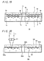
- FIG. 20 shows a schematic structure diagram of an example of a conventional optical recording medium 100.
- the thickness of the light transmission layer 103 formed in the surface on the side to be irradiated with the laser beam is preferably 3-177 [ ⁇ m].
- the optical recording medium 100 shown in FIG. 20 includes a non-magnetic supporting substrate 101 made of for example, glass, polycarbonate resin, polyolefine resin or the like having fine unevenness 110 such as predetermined pits and/or groove formed in the surface.
- a recording layer 102 is formed, corresponding to various optical recording mediums, such as that a metal reflection layer made of, for example, Al, Ag or the like, a dielectric layer made of, for example, Si 3 N 4 or the like, and a recording material layer made of magnetic substance such as TbFeCo, GdFeCo.
- a light transmission layer 103 made of, for example, ultraviolet curing resin is formed on the recording layer 102.
- a predetermined laser beam L is converged with an objective lens 111 and irradiated on a main surface opposite to the side of the non-magnetic supporting substrate 101 or in FIG. 20 on the side of a face in which the light transmission layer 103 is formed.
- the spherical aberration has a correlation with the thickness of the light transmission layer 103. If the thickness is shifted by ⁇ t with respect to a set value of the thickness of the light transmission layer 103, the spherical aberration increases proportional to the fourth power of numerical aperture N.A.. Therefore, if the numerical aperture N.A. of the objective lens is 0.85 assuming that the thickness deviation of the light transmission layer 103 of the DVD is ⁇ 30 [ ⁇ m], the spherical aberration has to be limited to ⁇ 7.4 [ ⁇ m] for the reason of the [expression 1] described below.
- the coma aberration is proportional to the third power of the numerical aperture N.A.. Therefore, it has to be limited to ⁇ 0.14° with respect to the skew standard of the DVD of 0.4° for the reason of [Expression 2] described below.
- the coma aberration has to be limited to ⁇ 0.087°for the reason of [Expression 4] described below.
- the coma aberration can be corrected by reducing the thickness of the light transmission layer 103.
- the thickness of the light transmission layer 103 For example, by reducing the thickness of the light transmission layer 103 from 0.6 [mm] to 0.1 [mm], sixfold skew margin can be obtained.
- the deviation of the thickness of the light transmission layer 103 has to be limited to ⁇ 4.6 [ ⁇ m] as described above.
- a predetermined accuracy is required for both of recording and reproduction.
- the deviation of the thickness has to be distributed to these and as a conclusion, the deviation of the thickness has to be limited to ⁇ 2.3 [ ⁇ m] which is half of the above described value.
- HD High Definition
- the signal pits or groove in the recording layer 102 is fine and the thickness of the light transmission layer 103 is very small in the optical recording medium for high density recording, particularly, it is necessary to improve corrosion resistance of the recording layer 102.
- the recording layer 102 is close to the air in an outermost peripheral portion 100a and an innermost portion 100b of the optical recording medium 100 of FIG. 20. Therefore, corrosion is likely to occur from this portion. For example, if recorded information is reproduced from the optical recording medium 100, this corrosion may induce reproduction failure, so that reliability of the optical recording medium 100 may be badly affected.
- the recording layer 102 composed of various materials exists between the light transmission layer 103 and the non-magnetic supporting substrate 101 in the outermost peripheral portion 100a and the innermost portion 100b, there is generated a problem that separation occurs from this portion as the thickness of the light transmission layer 103 decreases.
- an optical recording medium having a high reliability in which a recording beam or a reproduction beam is irradiated from the side of the light transmission layer, an occurrence of corrosion in the recording layer composing a large-capacity optical recording medium being avoided and separation of the light transmission layer in the outermost peripheral portion 100a and innermost portion 100b of the disc being suppressed.
- the present invention provides optical recording medium characterized in that a signal region constituted of information pits and/or groove are formed on a main surface of a disc-shaped non-magnetic supporting substrate and a recording layer and a reflection layer and a light transmission layer of 3-177 [ ⁇ m] in thickness are formed in the signal region, so that information reproduction and/or recording is carried out by irradiating the side of the light transmission layer with laser beam, the recording layer or the reflection layer being formed in the entire signal region but not formed in other region than the signal region in an outermost peripheral portion and an innermost portion of the disc-shaped non-magnetic substrate.
- the substrate and the light transmission protective layer are made in direct contact with each other in the outermost peripheral portion and the innermost portion, adhesiveness is improved, so that the disc hardness can be improved.
- the optical recording medium of the present invention is comprised a signal region composed of information pits and/or groove, a recording layer and/or a reflection layer formed by coating this signal region with material corresponding to the kind of a target recording medium and a light transmission layer of 3-177 [ ⁇ m] in thickness made of ultraviolet-curing resin, these layers being formed on a major surface of a non-magnetic supporting substrate made of for example, polycarbonate.
- a non-magnetic supporting substrate made of for example, polycarbonate.
- No film is formed on region other than the signal region on a outermost peripheral portion and a innermost portion of the disc shaped non-magnetic substrate. In the outermost peripheral portion and innermost portion, no recording layer or reflection layer exits between the light transmission layer and the nonmagnetic supporting substrate.
- optical recording medium of the present invention will be described by picking up examples.
- the optical recording medium of the present invention is not restricted to the examples described below.
- FIG. 1 shows a schematic sectional view of an example of the optical recording medium 10 of the present invention.
- the optical recording medium 10 shown in FIG. 1 is comprised of a non-magnetic supporting substrate 1 formed of for example, polycarbonate resin, polyolefine resin or the like having fine unevenness such as predetermined pits, grooves or the like, and recording layer 2 composed of metal layer made of Al, dielectric material layer made of ZnS-SiO 2 , optical recording layer made of GeSbTe and dielectric material layer made of ZnS-SiO 2 formed successively. Then, a light transmission layer 3 is formed on this recording layer 2 via for example, adhesive agent layer 4 of ultraviolet-curing resin.
- laser beam can be moved to any place on the disc by using the groove as a guide groove.
- the pits acts as information signal so that recorded information is read out by irradiating the pits with laser beam.
- Such fine unevennesses are formed spirally or coaxially in a predetermined configuration on the non-magnetic supporting substrate 1.
- a predetermined laser beam L is projected and focused to the main surface on an opposite side to the non-magnetic supporting substrate 1, namely from the side in which the light transmission layer 3 is formed in FIG. 1.
- polycarbonate resin polyolefine resin, acrylic resin, other resin and glass can be employed.
- the non-magnetic supporting substrate 1 can be produced by injection molding method (injection method) or photo polymerization method (2P method).
- the non-magnetic supporting substrate 1 may be formed of untransparent material such as metal as well as transparent material with respect to laser beam L.
- the light transmission layer 3 is preferably formed of material having a capacity of absorbing a predetermined wavelength of laser beam for recording and reproduction. More specifically, material having transmissivity of more than 90% with respect to laser beam is preferred.
- the thickness of the light transmission layer 3 is set to 3-177 [ ⁇ m] to achieve a large capacity.
- a high density recording capacity optical recording medium is achieved.
- the light transmission layer 3 can be formed by bonding thermoplastic resin film having a uniform thickness onto the non-magnetic supporting substrate 1. Further, the light transmission layer 3 may be formed also by interposing ultraviolet curing resin between the thermoplastic resin film and the non-magnetic supporting substrate 1, bonding these components and leaving cured by ultraviolet ray.
- This light transmission layer 3 may be also formed by bonding a thermoplastic resin film having adhesiveness onto the non-magnetic supporting substrate 1. Further, the light transmission layer 3 may be also formed by spin-coating the top face of the non-magnetic supporting substrate 1 with ultraviolet curing resin and then bonding the thermoplastic resin film on this layer. If the film is bonded by way of the ultraviolet curing resin, the thickness of the light transmission layer 3 is a sum of the thickness of the thermoplastic resin film and that of the ultraviolet curing resin after cured, and in the optical recording medium according to the present invention, this is 3-177 [ ⁇ m].
- thermoplastic resin film for example, polycarbonate resin or polyolefine may be used.
- Polycarbonate resin may be produced according to so-called phosgene method by reacting, for example, diphenol base material such as bisphenol A with phosgene under an existence of acid binder such as sodium hydrate.
- branched polycarbonate having phenol base hydroxyl group may be used as a branching agent and long-chain alkyl acid chloride or long-chain alkyl ester substituted phenol or the like may be used as an end stop agent.
- End long-chain alkyl branched polycarbonate resin for use as both the branching agent and end stop agent or a mixture of these materials may be used.
- thermoplastic resin is loaded onto a conventionally used extruder and melted by means of a heater. Then, it is extruded in the form of a sheet, and is formed to resin sheet by using a plurality of cooling rolls.
- optical recording medium 10 of the present invention is produced as a phase change type optical recording medium, a phase change material is used for material layer composing the recording layer 2.
- the phase change material is material which generates reversible condition change when laser beam is irradiated.
- material which generates reversible phase change between amorphous state and crystalline state is preferable and conventionally well known material such as chalcogen compound and single-element chalcogen may be used.
- gas additive such as nitrogen, oxygen
- material containing mainly Sb-Te system is particularly preferable. It is possible to add any element, for example, Se, Pd or In to this material as an applicable material.
- optical recording medium of the present invention can be applied to a magneto-optical recording medium as well as the phase change type optical recording medium.
- a layer of magneto-optical material is formed.
- magneto-optical recording material such as Tb-Fe system, Tb-Fe-Co system, Gd-Fe system and Gd-Fe-Co system can be applied.
- optical recording medium 10 of the present invention is formed in the form of ROM (Read Only Disc) type optical disc, as material layer composing the recording layer 2, a reflection layer is formed by employing well known metal material such as Al, Ag.
- a glass substrate 10 whose surface is polished sufficiently is prepared as shown in FIG. 2.
- This glass substrate 10 is placed on a rotating base (not shown) and then, by rotating this at a predetermined rotation speed, photo-resist 21 is applied in an equal thickness as shown in FIG. 3.
- the photo-resist 21 is exposed to a predetermined pattern by recording laser beam L.
- the recording laser beam L is fed by an equal distance for each turn in the radial direction of the glass substrate 20, so that groove latent image is generated at a predetermined interval, for example, spirally in the photo-resist 21.
- an object of the present invention is to obtain an optical recording medium capable of achieving a high density recording corresponding to a large capacity of 22 [GB], it is necessary to form a high-density guide groove and address in the aforementioned exposure process. Then, with cutting pitch set to about 0.6 [ ⁇ m], exposure was carried out. Because the recording layer and material layer produced in post process are buried in a groove formed by this cutting process, the exposure region needs to be formed relatively wider.
- a groove of 0.37 ⁇ 0.01 [ ⁇ m] may be formed.
- an optical recording medium of 120 [mm] in diameter for example, its signal region is a region of 24-58 [mm] in radius. If the recording is carried out at linear density of 0.13 [ ⁇ m/bit] with the aforementioned pitch, assuming that signal effectiveness is 80%, finally, an optical recording medium having a large capacity of 22 [GB] can be obtained.
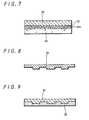
- the glass substrate 20 is developed with alkali developing solution to remove an exposed portion. Consequently, fine unevenness 21a of a predetermined pattern is formed on the glass substrate 20.
- surface conductive processing is carried out by electroless plating so as to form electroless plating layer 22 of NiP having a thickness of about 100 nm on the fine unevenness 21a.
- metallic plating layer 23 is formed on the electroless plating layer 22 in thickness of, for example, 0.3mm.
- the electroless plating layer 22 and the metallic plating layer 23 are removed from the glass substrate 20 so as to produce a metal master disc 24 shown in FIG. 8.
- this metal master disc 24 is subjected to heat treatment at high temperatures.
- This heat treatment is carried out at a temperature over 200°C, for example, in the air of normal pressure for about 30 minutes.
- this heat treatment may be carried out with natural convection type high-temperature drier, not only heating with far-infrared radiation and heating with a hot plate but also other various heating methods may be employed.
- Impurity adhering to the surface of the metal master disc 24 can be removed by this heat treatment so that releasability thereof can be improved.
- the surface is purified by irradiating the surface of the metal master disc 24 with far-infrared ray and by carrying out plasma irradiation, the releasability is improved.
- the metal master disc 24 is subjected to electro-plating so as to form metal plating layer 25. Then, the metal plating layer 25 is separated from the metal master disc 24 as shown in FIG. 10 so as to produce a stamper duplication disc 26.
- a region to which fine unevenness of the non-magnetic supporting substrate 1 is transferred serves for a signal region 30.
- the recording layer 2 is formed on this non-magnetic supporting substrate 1.
- This recording layer 2 is formed of material corresponding to various optical recording medium such as, for example, ROM type disc, phase change type optical disc and the like.
- metal layer of Al, dielectric layer made of ZnS-SiO 2 , optical recording layer of GeSbTe and dielectric layer of ZnS-SiO 2 are formed on the non-magnetic supporting substrate 1 in this order so as to form the recording layer 2.
- the recording layer 2 is not formed an entire region of the surface of the non-magnetic supporting substrate 1. Although the recording layer 2 is formed on an entire surface of the signal region 30 shown in FIG. 13, it is not formed in a region other than the signal region on the outermost peripheral portion and innermost peripheral portion of the disc.
- the recording layer 2 is not formed in a region far by b [mm] from the center, for example, 22 [mm] and in a region far by c [mm] from the outer end of the disc, for example, 1.5 [mm].
- the recording layer 2 is formed in a region d [mm] from 22 [mm] from the center up to 58.5 [mm].
- ultraviolet curing resin is coated in a region, for example, within the distance of 20-60 [mm] from the center of the non-magnetic supporting substrate 1 on which the recording layer 2 is formed, in thickness of for example, 30 [ ⁇ m] so as to produce adhesive agent layer 4.
- a transparent thermoplastic resin film of, for example, 119.5 [mm] in diameter, and 70 [ ⁇ m] in thickness is bonded by pressing and cured by irradiating with ultraviolet ray.
- the light transmission layer 3 of, 100 [ ⁇ m] in thickness with a deviation of ⁇ 2 [ ⁇ m] can be formed, so that the optical recording medium 10 of the present invention can be produced.
- the non-magnetic supporting substrate 1 and the light transmission layer 3 are placed in contact with each other by means of the adhesive agent layer 4 in the outermost peripheral portion 1a and innermost portion 1b of the non-magnetic supporting substrate 1, so that no material layer for forming the recording layer 2 exists there.
- adhesiveness in this portion is improved so that separation of the light transmission layer 4 can be avoided effectively thereby the strength of the disc hardness being improved.
- the recording layer 2 is not formed in region other than the signal region in the outermost peripheral portion 1a and innermost portion of the non-magnetic supporting substrate 1, the material of the recording layer 2 can be prevented from making contact with the air at an end of the disc, thereby corrosion of the recording layer 2 through this portion being avoided effectively. As a result, an optical recording medium having excellent corrosion resistance and optical performance can be obtained.
- the storage condition is 80°C, 80% in humidity for 1000 hours.
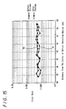
- FIG. 15 shows a measurement result of the error rate in the optical recording medium 10 of the present invention shown in FIG. 1.
- the axis of ordinate indicates the error rate and the abscissa axis indicates a distance from the center of the optical recording medium 10.
- a line 71 indicates the condition of the error rate before storage under the above described condition and a line 72 indicates the condition of the error rate after the storage under the above described condition.
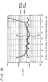
- FIG. 16 shows a measurement result of the error rate in the optical recording medium 100 having the conventional structure shown in FIG. 20.
- the axis of ordinate indicates the error rate and the abscissa axis indicates a distance from the center of the optical recording medium 100.
- a line 81 indicates the condition of the error rate before the storage under the above described condition and a line 82 indicates the condition of the error rate after the storage under the above described condition.
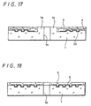
- a portion around a center hole 1h in the non-magnetic supporting substrate 1 is protruded so that this portion is formed thicker than the surrounding portion.
- the light transmission layer 3 for example 100 ⁇ m thick can be formed.
- thermoplastic resin film which forms the light transmission layer 3 it is possible to form fine unevenness such as pits and grooves preliminarily in the surface of thermoplastic resin film which forms the light transmission layer 3, to form a recording layer 40 by applying a predetermined material layer and then to bond this onto the recording layer 2 through the adhesive agent layer 4 so as to produce an optical recording medium having multiple recording layers.
- the recording layer 40 formed on the side of bonding with the non-magnetic supporting substrate 1 of the light transmission layer 3 is formed on an entire signal region on the surface of the light transmission layer 3, this is not formed on other region than the signal region in the outermost peripheral portion 3a and innermost peripheral portion 3b of the optical recording medium.
- thermoplastic resin sheet preliminarily, a conventionally well known method, that is, injection molding method or photo-polymerization method may be applied.
- the material layer for forming the recording layer 2 does not exist on a border between the non-magnetic supporting substrate 1 and the light transmission layer 3 in the outermost peripheral portion 1a and the innermost peripheral portion 1b of the non-magnetic supporting substrate 1. Consequently, adhesiveness between the non-magnetic supporting substrate 1 and the light transmission layer 3 in this portion is improved so that separation of the light transmission layer 4 can be avoided effectively, thereby leading to improvement of the strength and durability of the optical disc.
- the recording layer 2 is not formed in region other than the signal region in the outermost peripheral portion 1a and the innermost portion 1b of the non-magnetic supporting substrate 1, contact of the material for composing the recording layer 2 with the air at an end portion of the disc can be avoided, so that an occurrence of corrosion of the recording layer 2 from this portion can be avoided. As a result, an optical recording medium having excellent optical corrosion resistance and characteristic can be obtained.
Landscapes
- Physics & Mathematics (AREA)
- Optics & Photonics (AREA)
- Optical Record Carriers And Manufacture Thereof (AREA)
- Optical Recording Or Reproduction (AREA)
Abstract
Description
Claims (5)
- An optical recording medium comprising a signal region constituted of information pits line and/or groove are formed on a main surface of a disc-shaped non-magnetic supporting substrate, and a recording layer and/or a reflection layer and a light transmission layer of 3 to 177 [µm] in thickness are formed in the signal region, so that information reproduction and/or recording are carried out by irradiating the side of the light transmission layer with blue-violet laser beam, characterized in that the recording layer or the reflection layer being formed in the entire signal region but not formed in region other than the signal region in an outermost peripheral portion and an innermost portion of the supporting substrate.
- The optical recording medium according to claim 1 characterized in that the light transmission layer is formed of thermoplastic resin film.
- The optical recording medium according to claim 1 characterized in that the light transmission layer is formed of thermoplastic resin film and adhesive agent layer.
- The optical recording medium according to claim 1 characterized in that the light transmission layer is formed of thermoplastic resin film, anda signal region constituted of information pits line and/or groove are formed in the thermoplastic resin film on a side of bonding with supporting substrate and a recording layer and/or a reflection layer are formed in the signal region,the recording layer or the reflection layer on the side of bonding with the thermoplastic resin film being formed in the entire signal region of the thermoplastic resin film while not formed in region other than the signal region in an outermost peripheral portion and an innermost portion of the thermoplastic resin film.
- The optical recording medium according to claim 1 characterized in that
the supporting substrate has a protrusion which is formed around the center bore on the laser irradiated side of the supporting substrate and has a thickness greater than that of the surrounding portion.
Applications Claiming Priority (2)
| Application Number | Priority Date | Filing Date | Title |
|---|---|---|---|
| JP2000123133 | 2000-04-24 | ||
| JP2000123133A JP2001307381A (en) | 2000-04-24 | 2000-04-24 | Optical recording medium |
Publications (2)
| Publication Number | Publication Date |
|---|---|
| EP1152406A2 true EP1152406A2 (en) | 2001-11-07 |
| EP1152406A3 EP1152406A3 (en) | 2002-11-06 |
Family
ID=18633495
Family Applications (1)
| Application Number | Title | Priority Date | Filing Date |
|---|---|---|---|
| EP01109918A Withdrawn EP1152406A3 (en) | 2000-04-24 | 2001-04-24 | Optical recording medium |
Country Status (6)
| Country | Link |
|---|---|
| US (1) | US20010053122A1 (en) |
| EP (1) | EP1152406A3 (en) |
| JP (1) | JP2001307381A (en) |
| KR (1) | KR20010098826A (en) |
| CN (1) | CN1324074A (en) |
| TW (1) | TW519638B (en) |
Cited By (4)
| Publication number | Priority date | Publication date | Assignee | Title |
|---|---|---|---|---|
| EP1353327A3 (en) * | 2002-04-08 | 2003-12-03 | Fuji Photo Film Co., Ltd. | Optical information recording medium and production process thereof |
| WO2003107338A1 (en) * | 2002-06-14 | 2003-12-24 | Koninklijke Philips Electronics N.V. | Dual stack optical data storage medium and use of such medium |
| WO2003107339A1 (en) * | 2002-06-14 | 2003-12-24 | Koninklijke Philips Electronics N.V. | Optical data storage medium and use of such medium |
| EP1528547A4 (en) * | 2002-08-09 | 2008-07-02 | Sony Corp | Optical disk |
Families Citing this family (9)
| Publication number | Priority date | Publication date | Assignee | Title |
|---|---|---|---|---|
| EP1429325A4 (en) * | 2001-09-13 | 2006-05-31 | Tdk Corp | Optical recording medium manufacturing method |
| JP4071956B2 (en) * | 2001-11-13 | 2008-04-02 | Tdk株式会社 | Multilayer optical recording medium |
| JP2003203390A (en) * | 2001-12-28 | 2003-07-18 | Fuji Photo Film Co Ltd | Optical information recording medium |
| JP4860884B2 (en) * | 2002-03-11 | 2012-01-25 | Tdk株式会社 | Optical information medium |
| EP1617428A4 (en) * | 2003-04-18 | 2008-08-20 | Pioneer Corp | Stamper and method for production thereof |
| WO2006009161A1 (en) * | 2004-07-21 | 2006-01-26 | Matsushita Electric Industrial Co., Ltd. | Multi-layer information recording medium and manufacturing method thereof |
| US20070020561A1 (en) * | 2005-07-21 | 2007-01-25 | Kazuya Hisada | Manufacturing method and manufacturing apparatus for an optical data recording medium, and an optical data recording medium |
| JP4827848B2 (en) * | 2005-08-30 | 2011-11-30 | パナソニック株式会社 | Multilayer information recording medium manufacturing method, multilayer information recording medium manufacturing apparatus, and multilayer information recording medium manufacturing screen constituting the manufacturing apparatus |
| EP2446438B1 (en) | 2009-06-23 | 2014-03-05 | Thomson Licensing | Data disc, method and system of forming the disc |
Family Cites Families (3)
| Publication number | Priority date | Publication date | Assignee | Title |
|---|---|---|---|---|
| US4435801A (en) * | 1979-12-28 | 1984-03-06 | Rca Corporation | Information record with a thick overcoat |
| JPH0762919B2 (en) * | 1989-05-18 | 1995-07-05 | 三菱化学株式会社 | Play-only optical disc |
| JPH10326435A (en) * | 1997-03-25 | 1998-12-08 | Sony Corp | Optical recording medium and optical disk device |
-
2000
- 2000-04-24 JP JP2000123133A patent/JP2001307381A/en active Pending
-
2001
- 2001-04-20 TW TW090109530A patent/TW519638B/en not_active IP Right Cessation
- 2001-04-24 US US09/840,943 patent/US20010053122A1/en not_active Abandoned
- 2001-04-24 EP EP01109918A patent/EP1152406A3/en not_active Withdrawn
- 2001-04-24 KR KR1020010021957A patent/KR20010098826A/en not_active Withdrawn
- 2001-04-24 CN CN01117084A patent/CN1324074A/en active Pending
Cited By (6)
| Publication number | Priority date | Publication date | Assignee | Title |
|---|---|---|---|---|
| EP1353327A3 (en) * | 2002-04-08 | 2003-12-03 | Fuji Photo Film Co., Ltd. | Optical information recording medium and production process thereof |
| CN100339901C (en) * | 2002-04-08 | 2007-09-26 | 富士胶片株式会社 | Optical information recording medium and mfg method thereof |
| WO2003107338A1 (en) * | 2002-06-14 | 2003-12-24 | Koninklijke Philips Electronics N.V. | Dual stack optical data storage medium and use of such medium |
| WO2003107339A1 (en) * | 2002-06-14 | 2003-12-24 | Koninklijke Philips Electronics N.V. | Optical data storage medium and use of such medium |
| EP1770698A1 (en) * | 2002-06-14 | 2007-04-04 | Koninklijke Philips Electronics N.V. | Dual stack optical data storage medium and use of such medium |
| EP1528547A4 (en) * | 2002-08-09 | 2008-07-02 | Sony Corp | Optical disk |
Also Published As
| Publication number | Publication date |
|---|---|
| CN1324074A (en) | 2001-11-28 |
| TW519638B (en) | 2003-02-01 |
| US20010053122A1 (en) | 2001-12-20 |
| JP2001307381A (en) | 2001-11-02 |
| EP1152406A3 (en) | 2002-11-06 |
| KR20010098826A (en) | 2001-11-08 |
Similar Documents
| Publication | Publication Date | Title |
|---|---|---|
| US6023451A (en) | Optical recording medium and optical disk apparatus | |
| US6221455B1 (en) | Multi-layer optical disc and recording/reproducing apparatus | |
| KR100235363B1 (en) | Optical recording media | |
| US6246656B1 (en) | Reduced thickness of a light transmissive layer for a high density optical disc | |
| US6353592B1 (en) | Optical recording medium and optical disk device | |
| US5972459A (en) | Optical recording medium and optical disk apparatus | |
| US5154957A (en) | Optical information recording medium | |
| JPH10302309A (en) | Optical recording medium | |
| JPH1131337A (en) | Optical recording medium and optical disk device | |
| EP1152406A2 (en) | Optical recording medium | |
| JP4161716B2 (en) | Optical recording medium and optical disc apparatus | |
| JPH08203126A (en) | Optical information recording medium, optical information reproducing method, and optical information recording, reproducing and erasing method | |
| JP2001357571A (en) | Manufacturing method of optical recording medium | |
| JPH117658A (en) | Optical recording medium and optical disk device | |
| JP4085300B2 (en) | Phase change optical disk medium and method for initializing the medium | |
| JP2003233930A (en) | Optical recording medium | |
| JP2002092955A (en) | Optical recording medium and manufacturing method thereof | |
| JP2002092945A (en) | Optical recording medium and manufacturing method thereof | |
| JPH10312545A (en) | Information recording medium and recording / reproducing method thereof | |
| JPH06139619A (en) | Optical disk used exclusively for reproduction | |
| JP2009004093A (en) | Optical recording medium |
Legal Events
| Date | Code | Title | Description |
|---|---|---|---|
| PUAI | Public reference made under article 153(3) epc to a published international application that has entered the european phase |
Free format text: ORIGINAL CODE: 0009012 |
|
| AK | Designated contracting states |
Kind code of ref document: A2 Designated state(s): AT BE CH CY DE DK ES FI FR GB GR IE IT LI LU MC NL PT SE TR |
|
| AX | Request for extension of the european patent |
Free format text: AL;LT;LV;MK;RO;SI |
|
| PUAL | Search report despatched |
Free format text: ORIGINAL CODE: 0009013 |
|
| AK | Designated contracting states |
Kind code of ref document: A3 Designated state(s): AT BE CH CY DE DK ES FI FR GB GR IE IT LI LU MC NL PT SE TR |
|
| AX | Request for extension of the european patent |
Free format text: AL;LT;LV;MK;RO;SI |
|
| 17P | Request for examination filed |
Effective date: 20030407 |
|
| AKX | Designation fees paid |
Designated state(s): AT DE FR GB IT NL |
|
| STAA | Information on the status of an ep patent application or granted ep patent |
Free format text: STATUS: THE APPLICATION HAS BEEN WITHDRAWN |
|
| 18W | Application withdrawn |
Effective date: 20030827 |