EP1152253B1 - Beacon-assisted spacecraft attitude control systems and methods - Google Patents
Beacon-assisted spacecraft attitude control systems and methods Download PDFInfo
- Publication number
- EP1152253B1 EP1152253B1 EP01109641A EP01109641A EP1152253B1 EP 1152253 B1 EP1152253 B1 EP 1152253B1 EP 01109641 A EP01109641 A EP 01109641A EP 01109641 A EP01109641 A EP 01109641A EP 1152253 B1 EP1152253 B1 EP 1152253B1
- Authority
- EP
- European Patent Office
- Prior art keywords
- attitude
- signal
- spacecraft
- err
- beacon
- Prior art date
- Legal status (The legal status is an assumption and is not a legal conclusion. Google has not performed a legal analysis and makes no representation as to the accuracy of the status listed.)
- Expired - Lifetime
Links
Images


Classifications
-
- G—PHYSICS
- G01—MEASURING; TESTING
- G01S—RADIO DIRECTION-FINDING; RADIO NAVIGATION; DETERMINING DISTANCE OR VELOCITY BY USE OF RADIO WAVES; LOCATING OR PRESENCE-DETECTING BY USE OF THE REFLECTION OR RERADIATION OF RADIO WAVES; ANALOGOUS ARRANGEMENTS USING OTHER WAVES
- G01S3/00—Direction-finders for determining the direction from which infrasonic, sonic, ultrasonic, or electromagnetic waves, or particle emission, not having a directional significance, are being received
- G01S3/02—Direction-finders for determining the direction from which infrasonic, sonic, ultrasonic, or electromagnetic waves, or particle emission, not having a directional significance, are being received using radio waves
- G01S3/14—Systems for determining direction or deviation from predetermined direction
- G01S3/28—Systems for determining direction or deviation from predetermined direction using amplitude comparison of signals derived simultaneously from receiving antennas or antenna systems having differently-oriented directivity characteristics
- G01S3/30—Systems for determining direction or deviation from predetermined direction using amplitude comparison of signals derived simultaneously from receiving antennas or antenna systems having differently-oriented directivity characteristics derived directly from separate directional systems
-
- G—PHYSICS
- G01—MEASURING; TESTING
- G01S—RADIO DIRECTION-FINDING; RADIO NAVIGATION; DETERMINING DISTANCE OR VELOCITY BY USE OF RADIO WAVES; LOCATING OR PRESENCE-DETECTING BY USE OF THE REFLECTION OR RERADIATION OF RADIO WAVES; ANALOGOUS ARRANGEMENTS USING OTHER WAVES
- G01S19/00—Satellite radio beacon positioning systems; Determining position, velocity or attitude using signals transmitted by such systems
- G01S19/38—Determining a navigation solution using signals transmitted by a satellite radio beacon positioning system
-
- G—PHYSICS
- G01—MEASURING; TESTING
- G01S—RADIO DIRECTION-FINDING; RADIO NAVIGATION; DETERMINING DISTANCE OR VELOCITY BY USE OF RADIO WAVES; LOCATING OR PRESENCE-DETECTING BY USE OF THE REFLECTION OR RERADIATION OF RADIO WAVES; ANALOGOUS ARRANGEMENTS USING OTHER WAVES
- G01S5/00—Position-fixing by co-ordinating two or more direction or position line determinations; Position-fixing by co-ordinating two or more distance determinations
- G01S5/02—Position-fixing by co-ordinating two or more direction or position line determinations; Position-fixing by co-ordinating two or more distance determinations using radio waves
- G01S5/0247—Determining attitude
Landscapes
- Engineering & Computer Science (AREA)
- Radar, Positioning & Navigation (AREA)
- Remote Sensing (AREA)
- Physics & Mathematics (AREA)
- General Physics & Mathematics (AREA)
- Computer Networks & Wireless Communication (AREA)
- Control Of Position, Course, Altitude, Or Attitude Of Moving Bodies (AREA)
- Navigation (AREA)
Description
- The present invention relates generally to spacecraft attitude control and, more particularly, to beacon-assisted attitude control.
- Various conventional tracking systems and methods have been described (e.g., see
U.S. Patents 4,963,890 and5,926,130 ) for beacon-assisted spacecraft attitude control. The acquisition range, transient response and offset pointing of these systems and methods, however, has often been found to be less than satisfactory and they typically fail to operate autonomously (i.e., they require assistance from supporting control systems). - The present invention is directed to the autonomous orientation of a spacecraft to a desired spacecraft attitude Adsrd relative to a beacon that transmits a beacon signal. It discloses attitude control systems and methods which make direct use of received antenna powers and a signal modifier Smod to facilitate autonomous spacecraft attitude control, enhance conventional acquisition ranges and conventional transient responses and facilitate precise offset attitudes. These systems and methods avoid ambiguities that are introduced when received antenna powers are converted to angular distances.
- These goals are achieved with process steps that include:
- a) providing the spacecraft with at least three antennas A---N that have respective boresights arranged in a fixed angular relationship;
- b) from the antennas, receiving the beacon signal with power amplitudes PA --- PN that are each a measure of the angular distance between the boresight of a respective one of the antennas A---N and the beacon;
- c) combining the powers PA --- PN in accordance with the angular relationship to generate at least one attitude error signal Serr whose magnitude is a measure of the attitude difference between a current spacecraft attitude Acrnt and the desired spacecraft attitude Adsrd;
- d) generating a signal modifier Smod that increases with decreases in a sum power PΣ that is the sum of the signal powers PA --- PN;
- e) modifying the attitude error signal Serr with a term (1+Smod) to form an enhanced attitude error signal Serr
enhd ; and - f) orienting the spacecraft to reduce the enhanced attitude error signal Serr
enhd . - In one embodiment, the signal modifier Smod is set equal to n | Pmax - PΣ| m wherein n and m are positive numbers and the maximum power Pmax is the sum power PΣ when the attitude error signal Serr =0.
- Systems and spacecraft are also described for realizing the methods described above.
- The novel features of the invention are set forth with particularity in the appended claims. The invention will be best understood from the following description when read in conjunction with the accompanying drawings.
-
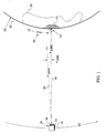
FIG. 1 is a view that illustrates a spatial relationship between a spacecraft, antennas carried by the spacecraft and a beacon that transmits a beacon signal; -
FIG. 2 is a flow chart that recites exemplary process steps of the invention which orient the attitude of the spacecraft ofFIG. 1 ; -
FIG. 3 is chart of angular relationships between the antennas ofFIG. 1 wherein the chart is organized along an exemplary coordinate system; -
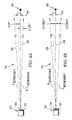
FIGS. 4A and 4B are side views of the spacecraft and beacon ofFIG. 1 that correspond to the coordinate system ofFIG. 3 ; -
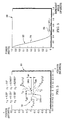
FIG. 5 is a graph that illustrates an exemplary relationship between received power and boresight angle in the antennas ofFIG. 1 ; -
FIG. 6 is a graph of sum power PΣ in the antennas ofFIG. 1 ; -
FIG. 7 is a graph of a transfer function which plots attitude error signal Serr versus attitude error Aerr, the graph illustrates an enhanced acquisition range that is realized with the process steps ofFIG. 2 ; -
FIGS. 8A and 8B use the chart ofFIG. 3 to further illustrate the enhanced acquisition range ofFIG. 6 ; and -
FIG. 9 is a block diagram of a control system of the invention that realizes the process steps ofFIG. 2 . - The present invention is especially suited for enhancing acquisition range, transient response and precision offset pointing in the orientation of a spacecraft to a desired spacecraft attitude Adsrd relative to a beacon that transmits a beacon signal. It achieves spacecraft attitude control via the direct use of received powers from beacon-sensing antennas and via the use of a signal modifier to form enhanced attitude error signals Serr
enhd . Accordingly, it facilitates autonomous spacecraft attitude control (i.e., it removes the need for supporting control systems), enhances conventional acquisition ranges and conventional transient responses and facilitates precise offset attitudes. - Concepts of the invention are illustrated in
FIG. 1 which shows the spacecraft and beacon and inFIG. 2 which recites process steps that realize the desired spacecraft attitude Adsrd. In particular,FIG. 1 shows aspacecraft 20 traveling in anorbital path 22 and having a spacecraft member (e.g., a face 24) directed towards abeacon 26. The beacon's signal is received inantennas 30 that are carried on thespacecraft body 31 and are arranged in a fixed spatial relationship with each other and with theface 24. - In practicing the invention, the
beacon 26 can be positioned in a variety of locations. As a first example, it can be positioned on thesurface 32 of an Earth 33 as shown inFIG. 1 . As a second example, it can be associated with an array ofcommunication cells 34 in a terrestrial area 35 (e.g., a country) which might originate and receive signals that are routed through thespacecraft 20. As a third example, thebeacon 26 may be carried on a vehicle such as theairplane 36 that is traveling along afight path 37. - In the embodiment illustrated in
FIG. 1 , the invention aids in orienting thespacecraft 20 so that theface 24 is directed towards thebeacon 26. That is, the spacecraft is oriented to have a desired attitude Adsrd as indicated by thevector 38 between theface 24 and thebeacon 26. When the spacecraft is instead oriented with a different current attitude Acrnt as indicated by thevector 39, it has an attitude error Aerr that is shown inFIG. 1 to be the difference between the current attitude Acrnt and the desired attitude Adsrd. - The
flow chart 50 ofFIG. 2 has afirst process step 51 that provides thespacecraft 20 with at least three antennas A---N which have respective boresights arranged in a fixed spatial relationship. An antenna's boresight is its electromagnetic axis and, accordingly, it defines the direction of maximum radiation (when radiating) or maximum sensitivity (when receiving). An exemplary antenna arrangement is shown in theangular plot 60 ofFIG. 3 . In this embodiment, three antennas A, B and C are provided and arranged to each diverge from a central axis (e.g., theaxis 38 ofFIG. 1 ) with an angle of 0.25°. - The
chart 60 plots these divergence angles on an exemplary orthogonal x, y coordinate system with the antenna A positioned on the x axis. In the coordinate system ofFIG. 3 , the 0.25° divergence causes antenna A to have angular components x1=-0.25°, y1=0° and causes antennas B and C to have respective angular components of x2=0.125°, y2=0.21651° and x3=0.125°, y3=-0.21651°. These exemplary divergence values indicate that the antennas A, B and C are laterally spaced on the antenna face (24 inFIG. 1 ) at 120° intervals about the desired attitude vector (38 inFIG. 1 ). - When the
spacecraft 20 ofFIG. 1 is oriented with the desired attitude Adsrd, thebeacon 26 will have aposition 26A at the origin of theplot 60 ofFIG. 3 . Accordingly, each antenna A, B and C will have a common angular distance rcm of 0.25° from thebeacon 26. When thespacecraft 20 is oriented with a different current attitude (e.g., Acrnt inFIG. 1 ) thebeacon 26 will be spaced from the origin of theplot 60. For example, it may then have aposition 26B and, from this position, the antennas A, B and C will respectively have angular distances r1, r2 and r3 from the beacon. When inposition 26B, the spacecraft attitude will have the attitude errors xerr and yerr shown inFIG. 3 . - The antenna and beacon angular relationships are further illustrated in
FIGS. 4A and 4B which indicate corresponding attitude errors xerr and yerr. These areside views FIG. 1 that are arranged in accordance with the coordinate system ofFIG. 3 . That is,FIGS. 4A and 4B respectively viewFIG. 1 along the x and y axes ofFIG. 3 . In these figures, thespacecraft face 24 is initially assumed to be directed along the desiredattitude vector 38 to thebeacon 26. InFIG. 4A , theboresight 74 of antenna A accordingly forms an angle of 0.25° with thevector 38 and theboresights 75 of antennas B and C form an oppositely directed angle of 0.125°. InFIG. 4B , the boresight of antenna A falls on thevector 38 and theboresights vector 38. - It is apparent in
FIG. 4A that if the current spacecraft attitude Acrnt were rotated 0.1° to align with the vector 39 (also shown inFIG. 1 ), then the boresight A angle would increase from 0.25 to 0.35 and the boresight angles B, C would decrease from 0.125° to 0.025°. It is similarly apparent inFIG. 4B that if the current spacecraft attitude Acrnt were rotated 0.1° to align with thevector 39, then the boresight B angle would increase from 0.21651° to 0.31651° and the boresight angle C would decrease from 0.21651° to 0.11651°. In these assumed rotations, the spacecraft attitude would have the indicated attitude errors xerr and yerr (for clarity of illustration, the angles depicted inFIGS. 4A and 4B have been greatly exaggerated). - The angular distances r1, r2 and r3 of
FIG. 3 can be detected in thespacecraft 20 ofFIG. 1 because the relationship between received beacon power and boresight angle is typically known. An exemplary relationship between received beacon power and boresight angle (angle from the beacon) is given by
FIG. 5 for an antenna diameter of 1.4427 meters and a wavelength of 0.010163 meters. Theplot 82 indicates a power minimum at approximately 0.5° boresight angle between amain lobe 84 and afirst side lobe 86. It is noted that the plot yields an unambiguous boresight angle only for those angles in which the power in themain lobe 84 exceeds thepeak power 87 of thefirst side lobe 86. - Fom the
plot 82 ofFIG. 5 , received power in theantennas 30 of thespacecraft 20 ofFIG. 1 can thus be converted to the angular distances r1 ,r2 and r3 ofFIG. 3 . From these known angular distances, the attitude errors xerr and yerr ofFIG. 3 can be expressed as
FIG. 3 that these attitudes are generally formed by adding squares of angular distances that are on a same side of the beacon signal and differencing squares of angular distances that are on different sides of the beacon signal. It is further noted that received antenna powers must be converted to angular distances before these relationships can be used in the generation of attitude-control error signals. - With this background description completed, attention is now returned to the
flow chart 50 ofFIG. 2 in whichprocess step 52 employs antennas with a known angular relationship to receive a beacon signal with signal powers PA --- PN that are each a measure of the angular distance between the boresight of a respective one of the antennas A---N and the beacon. Exemplary details of this step have been described above with reference toFIGS. 3-5 . -
Process step 53 ofFIG. 2 combines the signal powers PA --- PN in accordance with the angular relationship to generate at least one attitude error signal Serr whose magnitude is a measure of the attitude difference between a current spacecraft attitude Acrnt and the desired spacecraft attitude Adsrd. This step differs significantly from the calculated attitude errors xerr and yerr of equation (2) because it substitutes actual antenna power measurements for the angular distances r1 ,r2 and r3 which were converted from power measurements with knowledge of the relationship between received beacon power and boresight angle. - The method of
FIG. 2 continues withprocess step 54 which generates a signal modifier Smod that increases with decreases in a sum power P∑ that is the sum of the signal powers PA --- PN. In the exemplary antenna set ofFIG. 3 , the sum power PΣ is the sum of the powers received by antennas A, B and C (i.e., PA + PB+ PC). -
Process step 55 then modifies the attitude error signal Serr with a term (1+Smod) to form an enhanced attitude error signal Serrenhd andprocess step 56 orients the spacecraft to reduce the enhanced attitude error signal Serrenhd . In spacecraft attitude control, it has been found that the use of the signal powers PA --- PN significantly enhances acquisition range and the use of the term (1+Smod) significantly enhances transient response. - The teachings of these process steps can be practiced with various signal modifier Smod embodiments.. One embodiment can be defined with reference to
FIG. 6 in which aplot 88 indicates an antenna sum power PΣ as a function of attitude error Aerr. For the antennas ofFIG. 3 , the sum power PΣ = PA + PB + PC wherein PA, PB and PC are the received powers from the antennas A, B and C. As indicated inFIG. 6 , a maximum power Pmax is the maximum value of the sum power PΣ and this maximum power Pmax is received when the attitude error Aerr=0. - From
FIG. 6 , it is evident that one embodiment of the signal modifier Smod may be (Pmax - PΣ) which obviously increases as PΣ decreases in response to greater attitude errors. More generally, the signal modifier Smod may be chosen to be n|Pmax - PΣ|m in which n and m are positive numbers and the quantity (Pmax - PΣ) is replaced by its absolute value. Although (Pmax - PΣ) will always be positive or zero inFIG. 6 , this replacement accommodates offset method embodiments which will presently be described. - With this general embodiment of the signal modifier Smod, and with reference to the specific coordinate system of
FIG. 3 , enhanced attitude error signals Sxerr and Syerr may be defined as
-
FIG. 7 illustrates an exemplary attitude-control transfer function 90 that relates attitude error signal Serr as a function of attitude error Aerr. The transfer function has an initialinstantaneous slope 92 when the atttidude error is zero and approximates this initial slope over alimited attitude range 93. Because they use converted angular distances, the attitude errors of equations (2) are substantially true only in thelimited attitude range 93. Accordingly their use in an attitude control system will insure control acquisition only over this same limited range. - In contrast, it has been found that the combination of antenna power combinations (e.g., PB+PC-2PA) of equations (3) are effective over any expanded attitude range 94 in which the instantaneous slope of the transfer function has a slope greater than zero as exemplarized by the
slope 95. Accordingly, use of the attitude error signals of equations (3) will provide control acquisition over the substantially-enlarged attitude range 94. - The
limited attitude range 93 ofFIG. 6 basically corresponds to a boresight angle of ~0.4° inFIG. 5 which is the lowest power point for which theplot 82 yields an unambiguous conversion from received power to boresight angle. Theangular plot 60 ofFIG. 3 has been duplicated inFIGS. 8A and 8B withunambiguous circles 110 of radius 0.4° centered over antennas A, B and C inFIG. 8A . Controlling attitude with equations (2) is thus limited to an acquisition range defined by the shaded intersection 111 of theunambiguous circles 110. - In contrast, the expanded attitude range 94 of
FIG. 7 basically extends past thefirst side lobe 84 ofFIG. 5 to a boresight angle of -0.8°. Correspondingunambiguous circles 112 are shown inFIG. 8B which indicates that the shaded intersection 111 ofFIG. 8A has significantly expanded to ashaded intersection 113. As described above, increased boresight angles (e.g., angles that exceed -0.4° inFIG. 5 ) introduce ambiguities when antenna power is converted to angular distances. Direct use of antenna powers (e.g., as shown in equations (3)) avoid these ambiguities. - The general signal modifier n|Pmax - PΣ|m of equations (3) is particularly effective in enhancing transient response during spacecraft attitude control. An exemplary use of this term can be shown with reference to an arbitrary power threshold PthldA that is positioned at an attitude error of -0.226° in the plot 100 of sum power PΣ in
FIG. 6 . In this exemplary use, n and m are chosen such that the signal modifier is 2 |Pmax - PΣ|2 when the sum power PΣ is less than the power threshold PthldA and is 2|Pmax - PΣ| when the sum power PΣ is greater than the power threshold PthldA. Thus, the attitude error signals of equations (3) are increased when attitude error is large so as to reduce acquisition time but are decreased as attitude error diminishes so as to reduce control overshoot and/or ringing. - Obviously, the selection of n and m can be varied in many ways to condition transient response parameters (e.g., acquisition time, undershoot, overshoot and ringing). Additionally, they can be chosen with respect to more than one power threshold in the sum power PΣ plot 100 of
FIG. 6 to facilitate further control over the transient response parameters. - With reference to the
plot 88 of sum power PΣ inFIG. 6 , it can be seen that the value of the general signal modifier n|Pmax - PΣ|m approaches zero as the attitude error Aerr approaches zero. Thus the term {1 + n|Pmax - PΣ|m} approaches 1 as the attitude error Aerr approaches zero, i.e., the effect of the signal modifier diminishes as the spacecraft attitude error is reduced to very small values. - The process steps of
FIG. 2 can be realized with thecontrol system 120 ofFIG. 9 which includes anantenna system 122, anRF downconverter 124, a power measurement device such as thepower meter system 126, aspacecraft control processor 128 and atorque generation system 130. Theantenna system 122 can be formed, for example, with areflector 134 that directs a beacon signal (from thebeacon 26 ofFIG. 1 ) to feedhorns 135. Thereflector 134 causes thehorns 135 to appear to be invirtual positions 136 from which it is seen they are arranged in an angular relationship that causes theirboresights 137 to diverge. - After the received signals are downconverted in the
downconverter 124, they are measured in thepower meter system 126 and provided directly (i.e., without conversion to angular distances) to thespacecraft control processor 128. Aprocessor 140 within the spacecraft control processor may be programmed to perform the process steps 53, 54 and 55 ofFIG. 2 (when programmed, such process steps are sometimes referred to as procedures or algorithms). Theprocessor 140 thus receives the power signals (e.g., from antennas A, B and C) and, in response, forms an attitude error signal Serr and modifies this to an enhanced attitudeerror signal S errenhd 144. - The
spacecraft control processor 128 includes an attitude determination andcontrol system 148 which receives the enhanced attitude error signal Serrenhd along with attitude and attitude rate signals from attitude sensors 150 (e.g., earth sensors, sun sensors and rate gyros). From these input signals, the attitude determination andcontrol system 148 uses conventional feedback transfer functions (e.g., proportional plus derivative signals) and spacecraft dynamics transfer functions to generate control signals which are coupled to thetorque generation system 130. This latter system includes conventional torque generators (e.g.,thrusters 152,momentum wheels 153 and magnetic torquers 154) which respond to the control signals by effecting spacecraft attitude changes that act as anattitude feedback 156 that is sensed by theantenna system 122. - The systems and methods of the invention can be modified to direct the
vector 38 ofFIG. 1 to a spatial point that is offset from thebeacon 26. This is effected in thecontrol system 120 ofFIG. 9 by passing the enhanced attitude error signal Serrenhd through asummer 160 which is biased with an appropriate offsetsignal S off 162. Completing the process steps ofFIG. 2 will then cause thespacecraft 20 ofFIG. 1 to be directed along the desired offset vector. - Insertion of the offset signal 162 (and the resultant offset pointing) introduces asymmetries into the profile of the sum power PΣ plot 88 of
FIG. 6 . For offset pointing, it has therefore been found that acquisition range can be further improved if the enhanced attitude error signals Serrenhd recited above as equations (3) are modified to ones better suited to accommodate the offset-induced asymmetries. For the exemplary coordinate system ofFIG. 3 , the offset signal Soff would be expressed as xoff and yoff and an exemplary set of modified enhanced attitude error signals are given by

- In equations (4), PX and PY are power modifiers which enhance the precision of offset pointing because they provide offset corrections that improve the accuracy of the summed and differenced antenna powers PA, PB and PC. As the offset pointing is reduced to zero, it can be seen that equations (4) reduce to equations (3). In particular PX and PY reduce to zero because r1, r2 and r3 are then equal and, accordingly, α1, α2 and α3are also equal. Because of the offset of the antennas, the term Pmax
off - PΣ in equations (4) will not always be positive and, accordingly, the absolute value of this term was introduced above in equations (3). - It was mentioned above that the
beacon 26 ofFIG. 1 can be positioned in various locations to thereby assist in attitude control of spacecraft and, in particular, it can be associated with the array ofcommunication cells 32. The teachings of the invention can be practiced, for example, by placing the beacon at (or offset from) the common intersection of three communication cells (e.g., a point sometimes referred to as the triple cross-over point). In this embodiment, each of the antennas A, B and C ofFIG. 3 may be directed to transmit signals to and receive signals from respective one of the three cells. - Systems and methods have been described which make direct use of received antenna powers and a signal modifier Smod to facilitate autonomous spacecraft attitude control, enhance conventional acquisition ranges and conventional transient responses and facilitate precise offset attitudes. These systems and methods avoid ambiguities that are introduced when received antenna powers are converted to angular distances.
- The preferred embodiments of the invention described herein are exemplary and numerous modifications, variations and rearrangements can be readily envisioned to achieve substantially equivalent results, all of which are intended to be embraced within the scope of the invention as defined in the appended claims.
Claims (10)
- A method of orientating a spacecraft (20) to a desired spacecraft attitude (Adsrd) relative to a beacon (26) that transmits a beacon signal, the method comprising the steps of:providing (51) said spacecraft with at least three antennas (A---N; 30; 135) that have respective boresights (137) arranged in a fixed angular relationship;from said antennas (A---N; 30; 135), receiving (52) said beacon signal with signal powers (PA---PN) that are each a measure of the angular distance between the boresight of a respective one of said antennas (A-N; 30; 135) and said beacon (26);combining (53) said signal powers (PA---PN) in accordance with said angular relationship to generate at least one attitude error signal (Serr) whose magnitude is a measure of the attitude difference between a current spacecraft attitude (Acrnt) and said desired spacecraft attitude (Adsrd);generating (54) a signal modifier (Smod) that increases with decreases in a sum power (PΣ) that is the sum of said signal powers (PA---PN);modifying (55) said attitude error signal (Serr) with a term (1 + Smod) to form an enhanced attitude error signal (Serr
enhd ; 144);
andorienting (56) said spacecraft (20) to reduce said enhanced attitude error signal (Serrenhd ; 144). - The method of claim 1, further including the step of limiting said antennas to three antennas A, B and C.
- The method of claim 1, wherein said combining step (53) includes the steps of:adding signal powers of antennas whose boresights are substantially on the same side of said beacon; anddifferencing signal powers of antennas whose boresights are substantially on different sides of said beacon.
- The method of claim 1, wherein said generating step (54) includes the step of choosing said signal modifier (Smod) to be n|Pmax - PΣ|m wherein n and m are positive numbers and maximum power Pmax is said sum power PΣ when said attitude error signal (Serr) = 0.
- The method of claim 1, further including the step of combining said attitude error signal (Serr) with an offset signal (Soff; 162) to thereby cause said desired spacecraft attitude (Adsrd) to include a spatial offset from said beacon.
- The method of claim 5, further including the step of subtracting a power modifier from said signal powers (PA---PN) to facilitate realization of said spatial offset.
- An attitude control system (120) that orients a spacecraft (20) to a desired spacecraft attitude (Adsrd) relative to a beacon (26) that transmits a beacon signal, the system being characterized by:at least three antennas (A---N; 30; 135) that have respective boresights arranged with a fixed angular relationship, said antennas thus arranged to receive said beacon power with signal powers (PA---PN) that are each a measure of the angular distance between the boresight of a respective one of said antennas (A---N; 30; 135) and said beacon (26);a downconverter (124) that downconverts received signals of said antennas; anda control processor (140) that responds to said downconverter (124) and:a) combines (53) said signal powers (PA---PN) in accordance with said angular relationship to generate at least one attitude error signal (Serr) whose magnitude is a measure of the attitude difference between a current spacecraft attitude (Acrnt) and said desired spacecraft attitude (Adsrd);b) generates (54) a signal modifier (Smod) that increases with decreases in a sum power (PΣ) that is the sum of said signal powers (PA---PN);c) modifies (55) said attitude error signal (Serr) with a term (1 + Smod) to form an enhanced attitude error signal (Serr
enhd ; 144); andd) couples said enhanced attitude error signal (Serrenhd ; 144) to a torque-generation system (130). - The system of claim 7, characterized in that said control processor (140) forms said attitude error signal (Serr) as n|Pmax - PΣ|m wherein n and m are positive numbers and maximum power Pmax is said sum power PΣ when said attitude error signal (Serr) = 0.
- A spacecraft (20) having an attitude control system (120) that orients said spacecraft (20) to a desired spacecraft attitude (Adsrd) relative to a beacon that transmits a beacon (26) signal, the spacecraft (20) being characterized by:a spacecraft body (31);at least three antennas (A---N; 30; 135) carried on said body (31) and arranged with a fixed angular relationship, said antennas thus arranged to receive said beacon power with signal powers (PA---PN) that are each a measure of the angular distance between the boresight of a respective one of said antennas (A---N; 30; 135) and said beacon (26);a downconverter (124) carried in said body (31) to downconvert said signal powers (PA---PN);a power measurement system (126) carried in said body (31) to generate signal amplitudes (SA---SN) in response to downconverted signal powers (PA---PN) from said downconverter (124);a control processor (140) that responds to said downconverter (124) and:a) combines (53) said signal amplitudes (SA---SN) in accordance with said angular relationship to generate at least one attitude error signal (Serr) whose magnitude is a measure of the attitude difference between a current spacecraft attitude (Acrnt) and said desired spacecraft attitude (Adsrd);b) generates (54) a signal modifier (Smod) that increases with decreases in a sum power (PΣ) that is the sum of said signal powers (PA---PN);c) modifies (55) said attitude error signal (Serr) with a term (1 + Smod) to form an enhanced attitude error signal (Serr
enhd ; 144); andd) couples said enhanced attitude error signal (Serrenhd ;144) to a torque-generation system (130). - The spacecraft of claim 9, characterized in that said control processor (140) forms said attitude error signal (Serr) as n|Pmax - PΣ|m wherein n and m are positive numbers and maximum power Pmax is said sum power PΣ when said attitude error signal (Serr) = 0.
Applications Claiming Priority (2)
| Application Number | Priority Date | Filing Date | Title |
|---|---|---|---|
| US557378 | 1990-07-24 | ||
| US09/557,378 US6288671B1 (en) | 2000-04-25 | 2000-04-25 | Beacon-assisted spacecraft attitude control systems and methods |
Publications (3)
| Publication Number | Publication Date |
|---|---|
| EP1152253A2 EP1152253A2 (en) | 2001-11-07 |
| EP1152253A3 EP1152253A3 (en) | 2003-03-05 |
| EP1152253B1 true EP1152253B1 (en) | 2008-08-06 |
Family
ID=24225147
Family Applications (1)
| Application Number | Title | Priority Date | Filing Date |
|---|---|---|---|
| EP01109641A Expired - Lifetime EP1152253B1 (en) | 2000-04-25 | 2001-04-19 | Beacon-assisted spacecraft attitude control systems and methods |
Country Status (3)
| Country | Link |
|---|---|
| US (1) | US6288671B1 (en) |
| EP (1) | EP1152253B1 (en) |
| DE (1) | DE60135176D1 (en) |
Families Citing this family (4)
| Publication number | Priority date | Publication date | Assignee | Title |
|---|---|---|---|---|
| US6695262B2 (en) * | 2001-12-07 | 2004-02-24 | The Boeing Company | Spacecraft methods and structures for enhanced service-attitude accuracy |
| US7136014B2 (en) * | 2004-11-23 | 2006-11-14 | The Boeing Company | System and method for estimating the azimuth pointing angle of a moving monopulse antenna |
| US8640994B1 (en) * | 2010-09-27 | 2014-02-04 | The Boeing Company | Agile dedicated spacecraft for spinning microwave imagers and sounders |
| FR2988860A1 (en) * | 2012-03-29 | 2013-10-04 | Astrium Sas | SPACIAL ERROR CALIBRATION METHOD, METHOD AND SYSTEM FOR ATTITUDE ESTIMATION OF A GEAR |
Family Cites Families (4)
| Publication number | Priority date | Publication date | Assignee | Title |
|---|---|---|---|---|
| IT1199172B (en) | 1984-07-27 | 1988-12-30 | Selenia Ind Elettroniche | SYSTEM FOR THE END OF POINTING CONTROL OF ANTENNAS WITH RADIO FREQUENCY SENSOR, WITH WIDE ANGLE ACQUISITION FIELD |
| US5790071A (en) * | 1997-07-03 | 1998-08-04 | Lockheed Martin Corp. | Method for determining orientation and attitude of a satellite- or aircraft-borne phased-array antenna |
| US6018315A (en) * | 1998-05-04 | 2000-01-25 | Motorola, Inc. | Method and system for attitude sensing using monopulse GPS processing |
| US5926130A (en) | 1998-07-10 | 1999-07-20 | Hughes Electronics Corporation | Digital spacecraft antenna tracking system |
-
2000
- 2000-04-25 US US09/557,378 patent/US6288671B1/en not_active Expired - Lifetime
-
2001
- 2001-04-19 EP EP01109641A patent/EP1152253B1/en not_active Expired - Lifetime
- 2001-04-19 DE DE60135176T patent/DE60135176D1/en not_active Expired - Lifetime
Also Published As
| Publication number | Publication date |
|---|---|
| EP1152253A3 (en) | 2003-03-05 |
| EP1152253A2 (en) | 2001-11-07 |
| DE60135176D1 (en) | 2008-09-18 |
| US6288671B1 (en) | 2001-09-11 |
Similar Documents
| Publication | Publication Date | Title |
|---|---|---|
| US4883244A (en) | Satellite attitude determination and control system with agile beam sensing | |
| US7221317B2 (en) | Space-based lever arm correction in navigational systems employing spot beams | |
| US7333064B1 (en) | System and method for pointing and control of an antenna | |
| US8521427B1 (en) | Vehicle navigation using cellular networks | |
| US6825806B2 (en) | Satellite methods and structures for improved antenna pointing and wide field-of-view attitude acquisition | |
| US6731240B2 (en) | Method of tracking a signal from a moving signal source | |
| EP1760485B1 (en) | Boresight calibration of GPS satellite spot beam antenna using mobile GPS receivers | |
| US6289268B1 (en) | Attitude determination system and method | |
| US5597142A (en) | Spacecraft acquisition of orientation by scan of earth sensor field of view | |
| JPH0858699A (en) | Spaceship attitude determination system using sun sensor, earth sensor and space-to-ground link | |
| US7221316B2 (en) | Control segment-based lever-arm correction via curve fitting for high accuracy navigation | |
| US10476584B1 (en) | Systems and methods for autonomous operations of ground station networks | |
| US20090012662A1 (en) | Method and apparatus for determining a satellite attitude using crosslink reference signals | |
| US6504502B1 (en) | Method and apparatus for spacecraft antenna beam pointing correction | |
| US6771217B1 (en) | Phased array pointing determination using inverse pseudo-beacon | |
| US6567040B1 (en) | Offset pointing in de-yawed phased-array spacecraft antenna | |
| US20030036826A1 (en) | Spacecraft constellation formation keeping using inter-spacecraft distance measurement | |
| EP1152253B1 (en) | Beacon-assisted spacecraft attitude control systems and methods | |
| US6135389A (en) | Subterranean target steering strategy | |
| JP4295618B2 (en) | Satellite attitude adjustment for GPS initialization | |
| US6283415B1 (en) | Simplified yaw steering method for satellite antenna beam control | |
| US7129889B1 (en) | User segment-based lever arm correction via prescribed maneuver for high-accuracy navigation | |
| US6695262B2 (en) | Spacecraft methods and structures for enhanced service-attitude accuracy | |
| Wu et al. | Precision beacon-assisted attitude control for spaceway | |
| JPH02206779A (en) | Antenna tracking device of space navigating body |
Legal Events
| Date | Code | Title | Description |
|---|---|---|---|
| PUAI | Public reference made under article 153(3) epc to a published international application that has entered the european phase |
Free format text: ORIGINAL CODE: 0009012 |
|
| AK | Designated contracting states |
Kind code of ref document: A2 Designated state(s): AT BE CH CY DE DK ES FI FR GB GR IE IT LI LU MC NL PT SE TR |
|
| AX | Request for extension of the european patent |
Free format text: AL;LT;LV;MK;RO;SI |
|
| PUAL | Search report despatched |
Free format text: ORIGINAL CODE: 0009013 |
|
| AK | Designated contracting states |
Kind code of ref document: A3 Designated state(s): AT BE CH CY DE DK ES FI FR GB GR IE IT LI LU MC NL PT SE TR |
|
| AX | Request for extension of the european patent |
Extension state: AL LT LV MK RO SI |
|
| 17P | Request for examination filed |
Effective date: 20030822 |
|
| AKX | Designation fees paid |
Designated state(s): DE FR GB |
|
| GRAP | Despatch of communication of intention to grant a patent |
Free format text: ORIGINAL CODE: EPIDOSNIGR1 |
|
| GRAS | Grant fee paid |
Free format text: ORIGINAL CODE: EPIDOSNIGR3 |
|
| GRAA | (expected) grant |
Free format text: ORIGINAL CODE: 0009210 |
|
| AK | Designated contracting states |
Kind code of ref document: B1 Designated state(s): DE FR GB |
|
| REG | Reference to a national code |
Ref country code: GB Ref legal event code: FG4D |
|
| REF | Corresponds to: |
Ref document number: 60135176 Country of ref document: DE Date of ref document: 20080918 Kind code of ref document: P |
|
| PLBE | No opposition filed within time limit |
Free format text: ORIGINAL CODE: 0009261 |
|
| STAA | Information on the status of an ep patent application or granted ep patent |
Free format text: STATUS: NO OPPOSITION FILED WITHIN TIME LIMIT |
|
| 26N | No opposition filed |
Effective date: 20090507 |
|
| REG | Reference to a national code |
Ref country code: FR Ref legal event code: PLFP Year of fee payment: 16 |
|
| REG | Reference to a national code |
Ref country code: FR Ref legal event code: PLFP Year of fee payment: 17 |
|
| REG | Reference to a national code |
Ref country code: FR Ref legal event code: PLFP Year of fee payment: 18 |
|
| PGFP | Annual fee paid to national office [announced via postgrant information from national office to epo] |
Ref country code: FR Payment date: 20200427 Year of fee payment: 20 Ref country code: DE Payment date: 20200429 Year of fee payment: 20 |
|
| PGFP | Annual fee paid to national office [announced via postgrant information from national office to epo] |
Ref country code: GB Payment date: 20200427 Year of fee payment: 20 |
|
| REG | Reference to a national code |
Ref country code: DE Ref legal event code: R071 Ref document number: 60135176 Country of ref document: DE |
|
| REG | Reference to a national code |
Ref country code: GB Ref legal event code: PE20 Expiry date: 20210418 |
|
| PG25 | Lapsed in a contracting state [announced via postgrant information from national office to epo] |
Ref country code: GB Free format text: LAPSE BECAUSE OF EXPIRATION OF PROTECTION Effective date: 20210418 |