EP1151933A2 - Plastic container - Google Patents
Plastic container Download PDFInfo
- Publication number
- EP1151933A2 EP1151933A2 EP01104658A EP01104658A EP1151933A2 EP 1151933 A2 EP1151933 A2 EP 1151933A2 EP 01104658 A EP01104658 A EP 01104658A EP 01104658 A EP01104658 A EP 01104658A EP 1151933 A2 EP1151933 A2 EP 1151933A2
- Authority
- EP
- European Patent Office
- Prior art keywords
- base
- hinge
- lid
- sections
- container
- Prior art date
- Legal status (The legal status is an assumption and is not a legal conclusion. Google has not performed a legal analysis and makes no representation as to the accuracy of the status listed.)
- Granted
Links
Images


Classifications
-
- B—PERFORMING OPERATIONS; TRANSPORTING
- B65—CONVEYING; PACKING; STORING; HANDLING THIN OR FILAMENTARY MATERIAL
- B65D—CONTAINERS FOR STORAGE OR TRANSPORT OF ARTICLES OR MATERIALS, e.g. BAGS, BARRELS, BOTTLES, BOXES, CANS, CARTONS, CRATES, DRUMS, JARS, TANKS, HOPPERS, FORWARDING CONTAINERS; ACCESSORIES, CLOSURES, OR FITTINGS THEREFOR; PACKAGING ELEMENTS; PACKAGES
- B65D43/00—Lids or covers for rigid or semi-rigid containers
- B65D43/14—Non-removable lids or covers
- B65D43/16—Non-removable lids or covers hinged for upward or downward movement
- B65D43/162—Non-removable lids or covers hinged for upward or downward movement the container, the lid and the hinge being made of one piece
-
- B—PERFORMING OPERATIONS; TRANSPORTING
- B65—CONVEYING; PACKING; STORING; HANDLING THIN OR FILAMENTARY MATERIAL
- B65D—CONTAINERS FOR STORAGE OR TRANSPORT OF ARTICLES OR MATERIALS, e.g. BAGS, BARRELS, BOTTLES, BOXES, CANS, CARTONS, CRATES, DRUMS, JARS, TANKS, HOPPERS, FORWARDING CONTAINERS; ACCESSORIES, CLOSURES, OR FITTINGS THEREFOR; PACKAGING ELEMENTS; PACKAGES
- B65D2401/00—Tamper-indicating means
- B65D2401/60—Tearable part both of the container and of the closure
Definitions
- This invention relates generally to plastic containers having a lid, a base and a hinge joining the lid to the base.
- Plastic containers have long been used to carry food from a cafeteria, grocery store or restaurant for consumption at another location. Such containers have typically included a base and a lid sized and shaped to matingly engage the edges of one another for securely enclosing food items prior to storing and transporting the items. These containers are commonly thermoformed from a sheet of thermoplastic material.
- lids and bases are manufactured, sold and used in two separate pieces as individual lids and bases. Often the lids and the bases are made of like shapes and sizes so that the lids and the bases may nest within one another when not secured to one another along their edges. A drawback to such two-piece containers is that they are inefficient to use as the lids corresponding to the bases must be matched and aligned to the bases prior to joining them to the bases.
- Some plastic containers have overcome this drawback by hinging together the bases and the lids. These hinged containers are manufactured, sold and used as integral one piece units.
- the hinges of such containers are often comprised of one or more fold lines or creases in-between the lid and the base as shown for example in U.S. Patent No. 5,860,549.
- the hinges allow the lid to be folded and unfolded repeatedly onto the base along the fold line. This efficiency of the one-piece container is particularly appreciated by persons involved in the packing of food into the containers as they are able to efficiently load food into the base without concern for later locating matching lids, and aligning the edges of the lids with the edges of the bases to close the filled container.
- the present invention meets the above-described need in the art by providing in a preferred form of the invention a plastic container having a base and a lid hinged together by a hinge.
- the hinge has a series of relatively thick sections joined together by a series of relatively thin sections.
- the thin sections are sufficiently thin to be severed upon an initial folding of the hinge.
- the thick sections are sufficiently thick to remain at least partially intact during the initial folding.
- a method of packaging and unpackaging food products comprises the steps of placing food in the base of an open plastic container having a lid and a base joined by a hinge, closing the lid onto the base and partially fracturing the hinge, and subsequently re-opening the container and completely fracturing the hinge thereby providing access to the product in the base with the lid unattached.
- Fig. 1 illustrates a container 10 having a base 12, a lid 14 and a hinge 16 joining the lid to the base.
- the container 10 is thermoformed from a sheet of thermoplastic material preferably including a polypropylene or polyethylene resin.
- the base 12 has a bottom 18 and sides 20 that border the bottom.
- a bottom lip 22 extends from an upper portion of the sides 20.
- a protrusion 24 is formed in the bottom lip 22.
- the lid 14 has a top 26 and sides 28 that border the top.
- a top lip 30 extends from an upper portion of the sides 28.
- a groove 32 is formed in the top lip 30.
- the protrusion 24 and the groove 32 are sized and shaped to matingly engage one another in a tongue and groove manner.
- the hinge 16 is integrally formed to a side edge 34 of the base 12 and to a side edge 36 of the lid 14.
- the hinge 16 has a series of thin sections 38 and a series of thick sections 40.
- the hinge 16 extends along an axis 42 between the base 12 and the lid 14.
- the axis 42 is the fulcrum about which the base 12 and the lid 14 pivot.
- the axis 42 is preferably positioned to enable the flange 24 of the base 12 to engage the groove 30 of the lid 14.
- Fig. 2 illustrates a blade 44 used to impregnate or coin a sheet of plastic material to form the hinge 16.
- the blade 44 has a series of upper teeth 46 and a series of lower teeth 48 attached to a ridge 50.
- the ridge 50 is mounted to a block 52.
- the upper teeth 46 are preferably 1.4 millimeters in height as measured from the block 52.
- the lower teeth 48 are preferably 1.1 millimeters in height as measured from the block 52.
- Fig. 3 illustrates a side view of the blade 44 and of a striker plate 54 against which the blade coins a sheet of plastic material 56.
- the plastic material 56 is squeezed between the blade 44 and the striker plate 54.
- the compressive force of the upper teeth 46 against the striker plate 54 forms the thin sections 38 of the hinge 16.
- the compressive force of the lower teeth 48 against the striker plate 54 forms the thick sections 40 of the hinge 16.
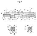
- the compression of the teeth 46 and 48 against the striker plate 54 carves out large and small indentations 58 and 60 in the plastic sheet 56 as best shown in Figs. 4a-c.
- Fig. 4a is a cross-sectional view of a section of the hinge 16 taken along the plane 4a-4a in Fig. 1.
- Each of the thin sections 38 includes a pair of upper inclined walls 62 that intersect at an upper crease 64.
- Each of the thin sections 38 extends between the upper inclined walls 62 and a top hinge surface 66.
- the top hinge surface 66 is preferably a planar surface formed by the striker plate 54.
- Each of the thick sections 40 includes a pair of lower inclined walls 68 that intersect at a lower crease 70, and a pair of side walls 72.
- Each of the thick sections 40 extends between the lower inclined walls 68 and the top hinge surface 66.
- the gauge of the sheet of thermoplastic material 56 from which the container 10 is formed is preferably 25 to 70 microns.
- the depths d 1 of the thin sections 38 between the upper crease lines 64 and the top hinge surface 66 are preferably about 25 percent to 50 percent of the gauge of the thermoplastic sheet 56.
- the depths d 2 of the thick sections 40 between the lower crease lines 70 and the top hinge surface 66 are preferably between about 75 percent and 95 percent of the gauge of the thermoplastic sheet 56.
- the lengths l 1 of the thin sections 38 between the side walls 72 are preferably about 4 millimeters.
- the lengths l 2 of the thick sections 40 between the side walls 72 are preferably about 2 millimeters.
- the depths d 1 and d 2 and the lengths l 1 and l 2 vary depending upon the type, the durability and the gauge of thermoplastic material used to form the hinge 16. Also, there is some variation in the exact measurements of thermoplastic material from which the containers 10 are made. Based upon the differences in the dimensions of the teeth 46 and 48 of the blade 44, the depths d 1 of the thin sections 38 are preferably about 15-25 percent less than the depths d 2 of the thick sections 40. The lengths l 1 of the thin sections 38 are preferably about twice the lengths l 2 of the thick sections 40.
- Figs. 4b and 4c are cross-sectional views of the hinge 16 taken along the planes 4b-4b and 4c-4c in Fig. 1.
- the thin sections 38 and the thick sections 40 align along the axis 42.
- the widths w 1 of the thin sections 38 and the widths w 2 of the thick sections 40 are preferably 1.2 millimeters. However, the widths w 1 of the thin sections 38 and the widths w 2 of the thick sections 40 need not be the same.
- the upper inclined walls 62 of the thin sections 38 form a V-shape.
- the lower inclined walls 68 of the thick sections also form a V-shape.
- the side walls 72 of the thick sections 40 together with the upper inclined walls 62 of the thin sections 38 define the large indentations 58.
- the lower inclined walls 68 define the small indentations 60.
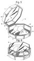
- the container 10 is typically used initially from its open position as shown in Fig. 1. Food or other items are placed in the base 12 and the lid 14 is moved pivotally about the axis 42 from an open position to a partially closed position as shown in Fig. 5. As the lid 14 is further moved pivotally about the axis 42 to a fully closed position upon the base 12, as shown in Fig. 6, tensile stress is applied to the hinge 16 transverse to the axis 42.
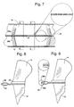
- the thin sections 38 are sufficiently thin so that the tensile stress caused by this pivotal movement of the lid 14 toward the base 12 weakens and severs them into two pieces 38a and 38b as shown in Figs. 7 and 8 as the container 10 is closed.
- the thick sections 40 are sufficiently thin so that the tensile stress applied to them transverse to the axis 42 during the initial closing action of the lid 14 upon the base 12 does not sever the thick sections.
- the thick sections 40 of the hinge 16 are at least partially intact.
- the thick sections 40 provide some stability to the container 10 so that the tongue 24 may be aligned and engaged to the groove 32 prior to the hinge 16 fully severing.
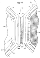
- the thick sections 40 Upon reopening of the container 10 by disengaging the tongue 24 from the groove 32 and pivotally moving the lid 14 away from the base 12, the thick sections 40 sever into two pieces 40a and 40b as shown in Fig. 10.
- the thick sections 40 are sufficiently thin so that they cannot withstand the force caused by pivotally reopening the container 10. It should be noted that the initial closing action of the container 10 partially weakens the thick sections 40. Thus, upon reopening the container 10, the thick sections 40 are further weakened and severed into two pieces 40a and 40b.
- the container 10 converts from a one-piece container to a two-piece container after one full cycle of closing and re-opening.
- the separate lid 14 and the separate base 12 may be fitted or nested together with the lid placed directly under the base.
- the top lip 30 and the bottom lip 22, the top sides 28 and the bottom sides 20, top 26 and the bottom 18 each lie in essentially parallel planes to one another.
- the lid 14 may be compactly stored under the base 12 to provide double the support and double the insulation of the base. This is particularly useful where the container. 10 is used to carry hot or heavy food.
- the base 12 may be used apart or together with the lid 14 to contain and heat food as in a microwave.
- the thick sections 40 fully sever as the lid 14 is moved to a fully opened position as shown in Fig. 10.
- the thick sections 40 may not fully sever as shown in Fig. 10. In such circumstances, the lid 14 and the base 12 may be pulled slightly apart to complete the severing of the thick sections 40.
- the preferred thermoplastic material 56 used to form the container 10 includes a polypropylene or polyethylene blend of resins.
- thermoplastic materials include polystyrene, oriented polystyrene, polyethylene terephthalate, amphorous polyethylene terephthalate (APET), and crystallized polyethylene terephthalate (CPET).
- plastic sheets comprised of other plastic resins may be used to form the container.
Abstract
Description
Claims (10)
- A plastic container having a base and a lid hinged together by a hinge that has a series of relatively thick sections joined together by a series of relatively thin sections, said thin sections being sufficiently thin to be severed upon an initial folding of said hinge and said thick sections being sufficiently thick to remain at least partially intact during the initial folding whereby the container may be filled with product and closed with the hinge becoming partially severed and weakened and may be later opened with the hinge becoming completely severed to separate the base and the lid.
- The plastic container of claim 1 wherein said hinge extends along an axis between said base and said lid and said thin sections and said thick sections are aligned along said axis.
- The plastic container of claim 1 comprised of a thermoplastic resin selected from the group consisting of polyethylene or polystyrene.
- The plastic container of claim 1 wherein the lengths of said thin sections are approximately twice the lengths of said thick sections.
- The plastic container of claim 1 wherein said thick sections have a thickness approximately 50 percent to 75 percent greater than the thickness of said thin sections.
- The plastic container of claim 1 wherein said thin sections have a substantially V-shaped cross-section.
- The plastic container of claim 1 wherein said thick sections have a substantially V-shaped cross-section.
- A method of packaging and unpackaging food products which comprises the steps of placing food in the base of an open plastic container having a lid and a base joined by a hinge, closing the lid onto the base and partially fracturing the hinge, and subsequently re-opening the container and completely fracturing the hinge thereby providing access to the product in the base with the lid unattached.
- The method of claim 8 wherein the food is heated and further comprising an additional step of nesting the base containing heated food upon the lid to assist in keeping the food warm.
- The method of claim 8 wherein the base and the food are heated and further comprising an additional step of nesting the heated base and food upon the lid to assist in keeping the food warm.
Applications Claiming Priority (2)
| Application Number | Priority Date | Filing Date | Title |
|---|---|---|---|
| US09/563,520 US6572909B1 (en) | 2000-05-03 | 2000-05-03 | Container having single-cycle hinge and use thereof |
| US563520 | 2000-05-03 |
Publications (3)
| Publication Number | Publication Date |
|---|---|
| EP1151933A2 true EP1151933A2 (en) | 2001-11-07 |
| EP1151933A3 EP1151933A3 (en) | 2003-01-29 |
| EP1151933B1 EP1151933B1 (en) | 2005-10-19 |
Family
ID=24250839
Family Applications (1)
| Application Number | Title | Priority Date | Filing Date |
|---|---|---|---|
| EP01104658A Expired - Lifetime EP1151933B1 (en) | 2000-05-03 | 2001-02-24 | Plastic container |
Country Status (7)
| Country | Link |
|---|---|
| US (1) | US6572909B1 (en) |
| EP (1) | EP1151933B1 (en) |
| AT (1) | ATE307066T1 (en) |
| DE (1) | DE60114076T2 (en) |
| DK (1) | DK1151933T3 (en) |
| ES (1) | ES2251423T3 (en) |
| HK (1) | HK1041471B (en) |
Cited By (5)
| Publication number | Priority date | Publication date | Assignee | Title |
|---|---|---|---|---|
| EP1571100A1 (en) * | 2004-02-18 | 2005-09-07 | DeSter.ACS Holding B.V. | Container for food, in particular for catering purposes |
| GB2446795A (en) * | 2007-02-23 | 2008-08-27 | Pregis Rigid Packaging Ltd | Container with hinge of reduced resilience |
| EP2364924A1 (en) | 2010-03-08 | 2011-09-14 | People on the Move B.V. | Plastic container, in particular for catering purposes |
| EP3699109A1 (en) * | 2019-02-22 | 2020-08-26 | Pro-Pac Ostendorf Plastic Thermoformfolien und Verpackungen Gmbh & Co. Kg | Container for storing food |
| US20220041343A1 (en) * | 2020-08-07 | 2022-02-10 | Portage Plastics Corporation | Tamper Evident Package Or Container |
Families Citing this family (46)
| Publication number | Priority date | Publication date | Assignee | Title |
|---|---|---|---|---|
| US20030168451A1 (en) * | 2002-03-07 | 2003-09-11 | Timothy Bohrer | Method of making one-piece lidded containers and containers made by the same |
| US20080087669A2 (en) | 2006-07-10 | 2008-04-17 | Inline Plastics Corp. | Tamper-resistant container with tamper-evident feature and method of forming same |
| US7246714B2 (en) * | 2003-08-15 | 2007-07-24 | Anchor Packaging, Inc. | Single point hinge for a container |
| US20050104487A1 (en) * | 2003-11-14 | 2005-05-19 | Joy Mangano | Nail polishing stand and storage cabinet |
| US7631776B2 (en) * | 2005-06-10 | 2009-12-15 | Pwp Industries | Tamper evident container with tear-apart parts |
| US8251242B2 (en) * | 2005-06-10 | 2012-08-28 | Pwp Industries | Tamper-evident container with extended band |
| US8083089B2 (en) | 2005-07-13 | 2011-12-27 | Pwp Industries Inc. | Versatile tamper-evident food container |
| US8251249B1 (en) | 2005-06-24 | 2012-08-28 | Pwp Industries | Hangable tamper resistant packaging system |
| US7568589B2 (en) * | 2005-06-24 | 2009-08-04 | Pwp Industries | Edge-tearing tamper-evident container |
| US8833589B2 (en) * | 2005-12-21 | 2014-09-16 | Pactiv Packaging Inc. | Enhanced tamper evident bowl with blocked tab |
| US8360262B2 (en) * | 2005-12-21 | 2013-01-29 | Pactiv Packaging Inc. | Integrated food packaging system having a cup, a container, and a cover |
| US7703632B2 (en) * | 2006-08-04 | 2010-04-27 | Kochanowski George E | Stackable and collapsible container |
| US20080116345A1 (en) * | 2006-11-21 | 2008-05-22 | O'malley Joseph | Locking tabs for roll stock stacking support |
| US20080308557A1 (en) * | 2007-06-15 | 2008-12-18 | Precision Packaging Products, Inc. | Tamper-evident seal for a container |
| US7669630B2 (en) * | 2007-06-22 | 2010-03-02 | Lap Shun Hui | Hole punch with automatic reinforcement ring placement |
| US20090090712A1 (en) * | 2007-10-09 | 2009-04-09 | Terry Vovan | Dip packaging system |
| US8127961B2 (en) * | 2007-11-10 | 2012-03-06 | Pwp Industries | Double ribbed secure container |
| US20090179039A1 (en) * | 2008-01-11 | 2009-07-16 | Tim Cimmerer | Domed casserole roaster container |
| US8322555B2 (en) * | 2008-05-13 | 2012-12-04 | Pwp Industries, Inc. | Resealable tamper-evident container assembly and lid |
| US20100102074A1 (en) * | 2008-10-28 | 2010-04-29 | Par-Pak Ltd. | Tamper evident container with frangible hinge |
| US10220986B2 (en) | 2009-03-06 | 2019-03-05 | Pactiv Corporation | Tamper evident container with full tab |
| US8146766B2 (en) | 2009-04-29 | 2012-04-03 | Pwp Industries | Enhanced secure container |
| JP5881618B2 (en) * | 2010-01-21 | 2016-03-09 | ネステク ソシエテ アノニム | Beverage machine with removable liquid supply reservoir |
| US20120024859A1 (en) * | 2010-07-30 | 2012-02-02 | Francesco Longoni | Container |
| US9624009B2 (en) | 2010-08-26 | 2017-04-18 | Dart Container Corporation | Tamper evident container |
| US8608008B2 (en) | 2010-08-26 | 2013-12-17 | Dart Container Corporation | Tamper evident container |
| US8895092B1 (en) * | 2011-03-16 | 2014-11-25 | Cryovac, Inc. | Package including a thermoplastic tray |
| USD675517S1 (en) | 2011-07-29 | 2013-02-05 | Dart Container Corporation | Container |
| USD712250S1 (en) | 2012-09-10 | 2014-09-02 | The Hillshire Brands Company | Packaging for food product |
| US9676527B2 (en) | 2013-03-21 | 2017-06-13 | Placon Corporation | Tamper resistant container |
| US9340350B2 (en) | 2014-08-15 | 2016-05-17 | Tekni-Plex, Inc. | Method and apparatus for forming a notched hinge connection in a thermoformed container |
| US9656785B2 (en) | 2015-06-30 | 2017-05-23 | Anchor Packaging, Inc. | Tamper evident plastic food container |
| US9796511B2 (en) | 2015-06-30 | 2017-10-24 | Anchor Packaging, Inc. | Tamper evident plastic food container |
| US9580219B2 (en) | 2015-06-30 | 2017-02-28 | Anchor Packaging | Tamper evident plastic food container |
| USD795651S1 (en) | 2015-06-30 | 2017-08-29 | Anchor Packaging, Inc. | Tamper evident plastic food container |
| US9475621B1 (en) | 2015-09-29 | 2016-10-25 | Anchor Packaging, Inc. | Tamper evident plastic food container with trigger open mechanism |
| US10220985B2 (en) | 2016-10-28 | 2019-03-05 | Genpak, Llc | Tamper-evident container with a tabbed hinge |
| US10894635B2 (en) | 2016-10-28 | 2021-01-19 | Genpak, Llc | Tamper-evident container with a wide tab extending beyond a hinge |
| US10889413B2 (en) | 2016-10-28 | 2021-01-12 | Genpak, Llc | Tamper-evident container with a tab extending beyond a hinge |
| US10351310B2 (en) | 2016-10-28 | 2019-07-16 | Genpak, Llc | Tamper-evident container with a bump near a tabbed hinge |
| NL2019712B1 (en) * | 2017-10-12 | 2019-04-23 | Paperfoam B V | Hinging product and apparatus and method for forming a hinging product |
| US10933788B2 (en) * | 2018-03-29 | 2021-03-02 | Lear Corporation | Foldable insert |
| US10669080B2 (en) | 2018-09-19 | 2020-06-02 | Sonoco Development, Inc. | Tamper evident closure |
| US11479389B2 (en) | 2020-05-20 | 2022-10-25 | Anchor Packaging, Llc | Tamper evident plastic food container |
| US11479392B2 (en) | 2020-05-20 | 2022-10-25 | Anchor Packaging, Llc | Tamper evident plastic food container |
| USD981992S1 (en) * | 2021-07-05 | 2023-03-28 | Guangdong Xizhongxi Technology Co., Ltd. | Set of wireless earphones and charging case |
Citations (7)
| Publication number | Priority date | Publication date | Assignee | Title |
|---|---|---|---|---|
| GB2014548A (en) * | 1978-02-17 | 1979-08-30 | Drg Uk Ltd | Moulded containers |
| US4220252A (en) * | 1979-08-27 | 1980-09-02 | Miles Laboratories, Inc. | Biological specimen process apparatus |
| US4421246A (en) * | 1982-06-21 | 1983-12-20 | Allied Corporation | Biological tissue cassette |
| EP0563781A1 (en) * | 1992-03-24 | 1993-10-06 | Mitsubishi Plastics Inc. | Plastic sheet with a ruled line for bending |
| FR2714891A1 (en) * | 1994-01-12 | 1995-07-13 | Robert Michel | Rigid food packaging dish with integral hinged lid |
| US5938068A (en) * | 1997-12-11 | 1999-08-17 | Dart Container | Container with removable cover |
| US6004251A (en) * | 1997-08-06 | 1999-12-21 | Klearfold, Inc. | Plastic sheets with scoring lines |
Family Cites Families (12)
| Publication number | Priority date | Publication date | Assignee | Title |
|---|---|---|---|---|
| US2915214A (en) * | 1956-10-05 | 1959-12-01 | Frankel Morris | Plastic containers |
| US3790062A (en) * | 1971-09-27 | 1974-02-05 | Packaging Corp America | Carton construction |
| US3937389A (en) | 1971-12-27 | 1976-02-10 | Harold Wind | Disposable food container |
| IT1061912B (en) | 1975-05-16 | 1983-04-30 | Mcdonalds Corp | PACKAGE FOR SWEET AND SIMILAR SANDWICHES AND RELATED MANUFACTURING PROCEDURE |
| US4189054A (en) | 1979-04-13 | 1980-02-19 | Liu Jack F | Product holder |
| FR2659627B1 (en) * | 1990-03-15 | 1992-05-22 | Rg Plastiques | PLASTIC TRAY LID. |
| US5851634A (en) * | 1992-08-11 | 1998-12-22 | E. Khashoggi Industries | Hinges for highly inorganically filled composite materials |
| US5366104A (en) | 1993-09-13 | 1994-11-22 | Fabri-Kal Corporation | Container with hinged lid |
| US5577627A (en) | 1995-06-07 | 1996-11-26 | Tenneco Packaging | Hinge structure for thermoformed plastic containers |
| US5957275A (en) | 1995-08-04 | 1999-09-28 | Lemaire; Real | Reusable container for coins or tokens |
| US5860549A (en) | 1995-09-27 | 1999-01-19 | Genpak, L.L.C. | Container for stabilizing a food dish |
| US5897011A (en) * | 1997-08-19 | 1999-04-27 | Anchor Packaging, Inc. | Clamshell container with tear-away lid |
-
2000
- 2000-05-03 US US09/563,520 patent/US6572909B1/en not_active Expired - Lifetime
-
2001
- 2001-02-24 DE DE60114076T patent/DE60114076T2/en not_active Expired - Lifetime
- 2001-02-24 AT AT01104658T patent/ATE307066T1/en not_active IP Right Cessation
- 2001-02-24 EP EP01104658A patent/EP1151933B1/en not_active Expired - Lifetime
- 2001-02-24 DK DK01104658T patent/DK1151933T3/en active
- 2001-02-24 ES ES01104658T patent/ES2251423T3/en not_active Expired - Lifetime
-
2002
- 2002-04-30 HK HK02103213.3A patent/HK1041471B/en not_active IP Right Cessation
Patent Citations (7)
| Publication number | Priority date | Publication date | Assignee | Title |
|---|---|---|---|---|
| GB2014548A (en) * | 1978-02-17 | 1979-08-30 | Drg Uk Ltd | Moulded containers |
| US4220252A (en) * | 1979-08-27 | 1980-09-02 | Miles Laboratories, Inc. | Biological specimen process apparatus |
| US4421246A (en) * | 1982-06-21 | 1983-12-20 | Allied Corporation | Biological tissue cassette |
| EP0563781A1 (en) * | 1992-03-24 | 1993-10-06 | Mitsubishi Plastics Inc. | Plastic sheet with a ruled line for bending |
| FR2714891A1 (en) * | 1994-01-12 | 1995-07-13 | Robert Michel | Rigid food packaging dish with integral hinged lid |
| US6004251A (en) * | 1997-08-06 | 1999-12-21 | Klearfold, Inc. | Plastic sheets with scoring lines |
| US5938068A (en) * | 1997-12-11 | 1999-08-17 | Dart Container | Container with removable cover |
Cited By (6)
| Publication number | Priority date | Publication date | Assignee | Title |
|---|---|---|---|---|
| EP1571100A1 (en) * | 2004-02-18 | 2005-09-07 | DeSter.ACS Holding B.V. | Container for food, in particular for catering purposes |
| GB2446795A (en) * | 2007-02-23 | 2008-08-27 | Pregis Rigid Packaging Ltd | Container with hinge of reduced resilience |
| GB2446795B (en) * | 2007-02-23 | 2011-11-30 | Pregis Rigid Packaging Ltd | Container and Method |
| EP2364924A1 (en) | 2010-03-08 | 2011-09-14 | People on the Move B.V. | Plastic container, in particular for catering purposes |
| EP3699109A1 (en) * | 2019-02-22 | 2020-08-26 | Pro-Pac Ostendorf Plastic Thermoformfolien und Verpackungen Gmbh & Co. Kg | Container for storing food |
| US20220041343A1 (en) * | 2020-08-07 | 2022-02-10 | Portage Plastics Corporation | Tamper Evident Package Or Container |
Also Published As
| Publication number | Publication date |
|---|---|
| US6572909B1 (en) | 2003-06-03 |
| EP1151933B1 (en) | 2005-10-19 |
| HK1041471B (en) | 2005-12-23 |
| EP1151933A3 (en) | 2003-01-29 |
| ATE307066T1 (en) | 2005-11-15 |
| DK1151933T3 (en) | 2006-02-27 |
| HK1041471A1 (en) | 2002-07-12 |
| DE60114076T2 (en) | 2006-07-13 |
| DE60114076D1 (en) | 2006-03-02 |
| ES2251423T3 (en) | 2006-05-01 |
Similar Documents
| Publication | Publication Date | Title |
|---|---|---|
| EP1151933B1 (en) | Plastic container | |
| US7992743B2 (en) | Edge-tearing tamper-evident container | |
| CA2354340C (en) | Displayable shipping carton | |
| AU2005269251B2 (en) | Stackable storage box for hanging files with separate base and lid | |
| US5108000A (en) | Recyclable materials caddy for hanging attachment to a waste receptacle | |
| CA2067951C (en) | Food package | |
| US8251249B1 (en) | Hangable tamper resistant packaging system | |
| US5577627A (en) | Hinge structure for thermoformed plastic containers | |
| US20040226989A1 (en) | Portable food dispenser | |
| US20140069930A1 (en) | Cutlery utensil dispensing package | |
| US20070063008A1 (en) | Perforated packaging | |
| NL2007197C2 (en) | Packaging unit for products like eggs, and mould and method there for. | |
| WO2003091120A1 (en) | Pizza box apparatus | |
| US20070031067A1 (en) | Plastic bag with cinching means and methods of using same | |
| US6910623B2 (en) | Paperboard can with an integrated lid having a hinge on the lid | |
| EP2495182A1 (en) | Easily disposable modular container for pizza and the like | |
| US8393529B2 (en) | EZ-fold modular pizza box | |
| US6230917B1 (en) | Lockable two-piece container | |
| EP1422151A1 (en) | Carton opening feature | |
| SE543091C2 (en) | Fastfood packaging with Cup-holder | |
| CA2758893A1 (en) | Flatbread container | |
| US20070012754A1 (en) | Slanted Clamshell Container with Sauce Holder | |
| WO2016071344A1 (en) | Flip-top container with improved resistance against breakage at the hinge connection | |
| EP1669306A1 (en) | Side-opening container with audible indication of opening | |
| EP0533457A1 (en) | Containers and blanks |
Legal Events
| Date | Code | Title | Description |
|---|---|---|---|
| PUAI | Public reference made under article 153(3) epc to a published international application that has entered the european phase |
Free format text: ORIGINAL CODE: 0009012 |
|
| AK | Designated contracting states |
Kind code of ref document: A2 Designated state(s): AT BE CH CY DE DK ES FI FR GB GR IE IT LI LU MC NL PT SE TR |
|
| AX | Request for extension of the european patent |
Free format text: AL;LT;LV;MK;RO;SI |
|
| PUAL | Search report despatched |
Free format text: ORIGINAL CODE: 0009013 |
|
| AK | Designated contracting states |
Designated state(s): AT BE CH CY DE DK ES FI FR GB GR IE IT LI LU MC NL PT SE TR |
|
| AX | Request for extension of the european patent |
Extension state: AL LT LV MK RO SI |
|
| 17P | Request for examination filed |
Effective date: 20030716 |
|
| AKX | Designation fees paid |
Designated state(s): AT BE CH CY DE DK ES FI FR GB GR IE IT LI LU MC NL PT SE TR |
|
| AXX | Extension fees paid |
Extension state: SI Payment date: 20030716 Extension state: AL Payment date: 20030716 Extension state: RO Payment date: 20030716 Extension state: LV Payment date: 20030716 Extension state: MK Payment date: 20030716 Extension state: LT Payment date: 20030716 |
|
| 17Q | First examination report despatched |
Effective date: 20031006 |
|
| GRAP | Despatch of communication of intention to grant a patent |
Free format text: ORIGINAL CODE: EPIDOSNIGR1 |
|
| GRAS | Grant fee paid |
Free format text: ORIGINAL CODE: EPIDOSNIGR3 |
|
| GRAA | (expected) grant |
Free format text: ORIGINAL CODE: 0009210 |
|
| AK | Designated contracting states |
Kind code of ref document: B1 Designated state(s): AT BE CH CY DE DK ES FI FR GB GR IE IT LI LU MC NL PT SE TR |
|
| AX | Request for extension of the european patent |
Extension state: AL LT LV MK RO SI |
|
| REG | Reference to a national code |
Ref country code: GB Ref legal event code: FG4D |
|
| REG | Reference to a national code |
Ref country code: CH Ref legal event code: EP |
|
| REG | Reference to a national code |
Ref country code: IE Ref legal event code: FG4D |
|
| REG | Reference to a national code |
Ref country code: HK Ref legal event code: GR Ref document number: 1041471 Country of ref document: HK |
|
| PG25 | Lapsed in a contracting state [announced via postgrant information from national office to epo] |
Ref country code: GR Free format text: LAPSE BECAUSE OF FAILURE TO SUBMIT A TRANSLATION OF THE DESCRIPTION OR TO PAY THE FEE WITHIN THE PRESCRIBED TIME-LIMIT Effective date: 20060119 |
|
| REG | Reference to a national code |
Ref country code: SE Ref legal event code: TRGR |
|
| PGFP | Annual fee paid to national office [announced via postgrant information from national office to epo] |
Ref country code: IE Payment date: 20060214 Year of fee payment: 6 |
|
| REG | Reference to a national code |
Ref country code: CH Ref legal event code: NV Representative=s name: PATENTANWALTSBUERO JEAN HUNZIKER |
|
| PGFP | Annual fee paid to national office [announced via postgrant information from national office to epo] |
Ref country code: DK Payment date: 20060217 Year of fee payment: 6 |
|
| PGFP | Annual fee paid to national office [announced via postgrant information from national office to epo] |
Ref country code: AT Payment date: 20060221 Year of fee payment: 6 |
|
| PGFP | Annual fee paid to national office [announced via postgrant information from national office to epo] |
Ref country code: PT Payment date: 20060224 Year of fee payment: 6 |
|
| PGFP | Annual fee paid to national office [announced via postgrant information from national office to epo] |
Ref country code: CH Payment date: 20060227 Year of fee payment: 6 |
|
| REG | Reference to a national code |
Ref country code: DK Ref legal event code: T3 |
|
| PG25 | Lapsed in a contracting state [announced via postgrant information from national office to epo] |
Ref country code: LU Free format text: LAPSE BECAUSE OF NON-PAYMENT OF DUE FEES Effective date: 20060228 Ref country code: MC Free format text: LAPSE BECAUSE OF NON-PAYMENT OF DUE FEES Effective date: 20060228 |
|
| REF | Corresponds to: |
Ref document number: 60114076 Country of ref document: DE Date of ref document: 20060302 Kind code of ref document: P |
|
| LTIE | Lt: invalidation of european patent or patent extension |
Effective date: 20051019 |
|
| REG | Reference to a national code |
Ref country code: ES Ref legal event code: FG2A Ref document number: 2251423 Country of ref document: ES Kind code of ref document: T3 |
|
| ET | Fr: translation filed | ||
| PLBE | No opposition filed within time limit |
Free format text: ORIGINAL CODE: 0009261 |
|
| STAA | Information on the status of an ep patent application or granted ep patent |
Free format text: STATUS: NO OPPOSITION FILED WITHIN TIME LIMIT |
|
| 26N | No opposition filed |
Effective date: 20060720 |
|
| PGFP | Annual fee paid to national office [announced via postgrant information from national office to epo] |
Ref country code: FI Payment date: 20070226 Year of fee payment: 7 |
|
| PG25 | Lapsed in a contracting state [announced via postgrant information from national office to epo] |
Ref country code: CH Free format text: LAPSE BECAUSE OF NON-PAYMENT OF DUE FEES Effective date: 20070228 Ref country code: LI Free format text: LAPSE BECAUSE OF NON-PAYMENT OF DUE FEES Effective date: 20070228 |
|
| PG25 | Lapsed in a contracting state [announced via postgrant information from national office to epo] |
Ref country code: PT Free format text: LAPSE BECAUSE OF NON-PAYMENT OF DUE FEES Effective date: 20070824 |
|
| REG | Reference to a national code |
Ref country code: PT Ref legal event code: MM4A Free format text: LAPSE DUE TO NON-PAYMENT OF FEES Effective date: 20070824 |
|
| REG | Reference to a national code |
Ref country code: DK Ref legal event code: EBP Ref country code: CH Ref legal event code: PL |
|
| PG25 | Lapsed in a contracting state [announced via postgrant information from national office to epo] |
Ref country code: AT Free format text: LAPSE BECAUSE OF NON-PAYMENT OF DUE FEES Effective date: 20070224 |
|
| REG | Reference to a national code |
Ref country code: IE Ref legal event code: MM4A |
|
| PG25 | Lapsed in a contracting state [announced via postgrant information from national office to epo] |
Ref country code: IE Free format text: LAPSE BECAUSE OF NON-PAYMENT OF DUE FEES Effective date: 20070226 Ref country code: DK Free format text: LAPSE BECAUSE OF NON-PAYMENT OF DUE FEES Effective date: 20070228 |
|
| PG25 | Lapsed in a contracting state [announced via postgrant information from national office to epo] |
Ref country code: TR Free format text: LAPSE BECAUSE OF FAILURE TO SUBMIT A TRANSLATION OF THE DESCRIPTION OR TO PAY THE FEE WITHIN THE PRESCRIBED TIME-LIMIT Effective date: 20051019 |
|
| PG25 | Lapsed in a contracting state [announced via postgrant information from national office to epo] |
Ref country code: FI Free format text: LAPSE BECAUSE OF NON-PAYMENT OF DUE FEES Effective date: 20080224 |
|
| PG25 | Lapsed in a contracting state [announced via postgrant information from national office to epo] |
Ref country code: CY Free format text: LAPSE BECAUSE OF FAILURE TO SUBMIT A TRANSLATION OF THE DESCRIPTION OR TO PAY THE FEE WITHIN THE PRESCRIBED TIME-LIMIT Effective date: 20051019 |
|
| PG25 | Lapsed in a contracting state [announced via postgrant information from national office to epo] |
Ref country code: BE Free format text: LAPSE BECAUSE OF NON-PAYMENT OF DUE FEES Effective date: 20150228 |
|
| PGRI | Patent reinstated in contracting state [announced from national office to epo] |
Ref country code: BE Effective date: 20150612 |
|
| REG | Reference to a national code |
Ref country code: FR Ref legal event code: PLFP Year of fee payment: 16 |
|
| PGFP | Annual fee paid to national office [announced via postgrant information from national office to epo] |
Ref country code: IT Payment date: 20160225 Year of fee payment: 16 Ref country code: NL Payment date: 20160226 Year of fee payment: 16 Ref country code: DE Payment date: 20160229 Year of fee payment: 16 Ref country code: ES Payment date: 20160217 Year of fee payment: 16 |
|
| PGFP | Annual fee paid to national office [announced via postgrant information from national office to epo] |
Ref country code: FR Payment date: 20160226 Year of fee payment: 16 Ref country code: GB Payment date: 20160211 Year of fee payment: 16 Ref country code: SE Payment date: 20160222 Year of fee payment: 16 Ref country code: BE Payment date: 20160225 Year of fee payment: 16 |
|
| PG25 | Lapsed in a contracting state [announced via postgrant information from national office to epo] |
Ref country code: BE Free format text: LAPSE BECAUSE OF NON-PAYMENT OF DUE FEES Effective date: 20170228 |
|
| REG | Reference to a national code |
Ref country code: DE Ref legal event code: R119 Ref document number: 60114076 Country of ref document: DE |
|
| REG | Reference to a national code |
Ref country code: SE Ref legal event code: EUG |
|
| REG | Reference to a national code |
Ref country code: NL Ref legal event code: MM Effective date: 20170301 |
|
| GBPC | Gb: european patent ceased through non-payment of renewal fee |
Effective date: 20170224 |
|
| PG25 | Lapsed in a contracting state [announced via postgrant information from national office to epo] |
Ref country code: NL Free format text: LAPSE BECAUSE OF NON-PAYMENT OF DUE FEES Effective date: 20170301 Ref country code: SE Free format text: LAPSE BECAUSE OF NON-PAYMENT OF DUE FEES Effective date: 20170225 |
|
| REG | Reference to a national code |
Ref country code: FR Ref legal event code: ST Effective date: 20171031 |
|
| PG25 | Lapsed in a contracting state [announced via postgrant information from national office to epo] |
Ref country code: FR Free format text: LAPSE BECAUSE OF NON-PAYMENT OF DUE FEES Effective date: 20170228 Ref country code: DE Free format text: LAPSE BECAUSE OF NON-PAYMENT OF DUE FEES Effective date: 20170901 |
|
| REG | Reference to a national code |
Ref country code: BE Ref legal event code: MM Effective date: 20170228 |
|
| PG25 | Lapsed in a contracting state [announced via postgrant information from national office to epo] |
Ref country code: IT Free format text: LAPSE BECAUSE OF NON-PAYMENT OF DUE FEES Effective date: 20170224 Ref country code: GB Free format text: LAPSE BECAUSE OF NON-PAYMENT OF DUE FEES Effective date: 20170224 |
|
| REG | Reference to a national code |
Ref country code: ES Ref legal event code: FD2A Effective date: 20180628 |
|
| PG25 | Lapsed in a contracting state [announced via postgrant information from national office to epo] |
Ref country code: ES Free format text: LAPSE BECAUSE OF NON-PAYMENT OF DUE FEES Effective date: 20170225 |