EP1151820A2 - Improvements in thermal welding - Google Patents
Improvements in thermal welding Download PDFInfo
- Publication number
- EP1151820A2 EP1151820A2 EP01303893A EP01303893A EP1151820A2 EP 1151820 A2 EP1151820 A2 EP 1151820A2 EP 01303893 A EP01303893 A EP 01303893A EP 01303893 A EP01303893 A EP 01303893A EP 1151820 A2 EP1151820 A2 EP 1151820A2
- Authority
- EP
- European Patent Office
- Prior art keywords
- cryogen
- welding
- carbon dioxide
- cooling
- friction stir
- Prior art date
- Legal status (The legal status is an assumption and is not a legal conclusion. Google has not performed a legal analysis and makes no representation as to the accuracy of the status listed.)
- Granted
Links
Images


Classifications
-
- B—PERFORMING OPERATIONS; TRANSPORTING
- B23—MACHINE TOOLS; METAL-WORKING NOT OTHERWISE PROVIDED FOR
- B23K—SOLDERING OR UNSOLDERING; WELDING; CLADDING OR PLATING BY SOLDERING OR WELDING; CUTTING BY APPLYING HEAT LOCALLY, e.g. FLAME CUTTING; WORKING BY LASER BEAM
- B23K20/00—Non-electric welding by applying impact or other pressure, with or without the application of heat, e.g. cladding or plating
- B23K20/12—Non-electric welding by applying impact or other pressure, with or without the application of heat, e.g. cladding or plating the heat being generated by friction; Friction welding
- B23K20/122—Non-electric welding by applying impact or other pressure, with or without the application of heat, e.g. cladding or plating the heat being generated by friction; Friction welding using a non-consumable tool, e.g. friction stir welding
- B23K20/123—Controlling or monitoring the welding process
- B23K20/1235—Controlling or monitoring the welding process with temperature control during joining
-
- B—PERFORMING OPERATIONS; TRANSPORTING
- B23—MACHINE TOOLS; METAL-WORKING NOT OTHERWISE PROVIDED FOR
- B23K—SOLDERING OR UNSOLDERING; WELDING; CLADDING OR PLATING BY SOLDERING OR WELDING; CUTTING BY APPLYING HEAT LOCALLY, e.g. FLAME CUTTING; WORKING BY LASER BEAM
- B23K37/00—Auxiliary devices or processes, not specially adapted for a procedure covered by only one of the other main groups of this subclass
- B23K37/003—Cooling means for welding or cutting
-
- B—PERFORMING OPERATIONS; TRANSPORTING
- B23—MACHINE TOOLS; METAL-WORKING NOT OTHERWISE PROVIDED FOR
- B23K—SOLDERING OR UNSOLDERING; WELDING; CLADDING OR PLATING BY SOLDERING OR WELDING; CUTTING BY APPLYING HEAT LOCALLY, e.g. FLAME CUTTING; WORKING BY LASER BEAM
- B23K2103/00—Materials to be soldered, welded or cut
- B23K2103/08—Non-ferrous metals or alloys
- B23K2103/10—Aluminium or alloys thereof
Definitions
- the present invention relates to thermal welding processes and in particular to methods of cooling work pieces during a thermal welding process.
- Cryogens particularly liquid nitrogen, and solid carbon dioxide have been used to provide enhanced cooling to arc welding (i.e. fusion) processes in order to enable high quality welds to be produced rapidly without thermal distortion of the workpieces, workpieces of relatively soft metals and alloys such as aluminium and aluminium alloys being particularly prone to distortion and reduction tensile strength.
- Fusion welding processes employing such cooling are, for example, described in GB-A-1 552 660; GB-A-0 764 336; WO-A-95/236 69; CN-A-1 110 206; JP-A-04-0 288 991; JP-A-02-0 052 173; JP-A-60-0 033 881; JP-A-60-0 018 292; JP-A-52-0 076 243 and SU-A- 414 066.
- Friction stir welding is an alternative welding process to electric arc welding. Examples of friction stir welding are disclosed in WO-A-95 26254, US-A-5 460 317 and US-A- 5 813 592. Difficulties still arise however in reliably and rapidly forming stress and strain free welds when joining two workpieces by friction stir welding.
- a tool which comprises a shank, a body (sometimes with cooling fins), a shoulder and a pin.
- the tool is usually made from tool steel and may have a specialised coating. The too is inserted into what is, in essence, a milling machine. The pin is lowered onto the two plates to be joined. The rotation of the pin heats the metal until it softens. At this point the pin is pushed downwards so that the shoulder comes into contact with the metal plates. The shoulder has a concave profile so that the tool locates the plasticised metal displaced by the pin. The should now beings to heat a larger volume of the metal.
- a method of friction stir welding together at least two metallic workpieces includes the step of applying at or adjacent to a heated welding zone at least one jet of cryogen.
- the cryogen may be in the form of a liquid cryogen, for example, liquid nitrogen or liquid argon.
- the cryogen may be solid carbon dioxide.
- cryogen is applied to the welding zone through a plurality of nozzles.
- the cryogen may be a liquid cryogen for example liquid nitrogen or liquid argon.
- the cryogen could be solid carbon dioxide or a mixture of solid carbon dioxide together with a liquid cryogen.
- the choice of the cryogen is dependent on the process and the material of the metallic plates being welded.
- the amount of cooling and location to which the cryogen is applied is strictly controlled in order to achieve the desired effect. This is achieved by applying the cryogen via a nozzle or nozzles directed on to the surface of the work pieces being welded.
- the size and geometry of the nozzles is a critical factor for controlling the cooling footprint as well as the location and orientation of the cooling jets.
- a butt joint of two aluminium alloy plates 20, each 6.35 mm thick was made by friction stir welding employing a friction stir welding tool 22.
- a jet of solid carbon dioxide particles was applied on the top side of the weld from a nozzle 24.
- the point of application of the carbon dioxide was arranged to trail the welding point by approximately 20 mm.
- the vertical stand off distance between the tip of the nozzle 24 and the weld was 20mm.
- the nozzle 24 had a diameter of 1 mm.
- the jet of solid carbon dioxide particles was formed conventionally (for example by causing a pressurised liquid stream of carbon dioxide to flow from a source (not shown) thereof via solenoid valve 26 through the nozzle 24).
- the carbon dioxide was supplied at a rate of 1.5 kg/min and at a supply pressure of 22 bar.
- the friction stir welding tool 22 was rotated at a speed of 355 revolutions per minute and was translated at 95.2 mm per minute.
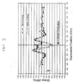
- FIG. 3 shows the difference between weld samples made with and without cryogenic cooling in accordance with the invention.
- Figure 3 shows a substantial reduction in the tensile stresses in the weld zone.
- the cooling actually created compressive stresses in this area. Creation of such compressive stresses is recognised in the art as a highly desirable feature.
Landscapes
- Engineering & Computer Science (AREA)
- Mechanical Engineering (AREA)
- Physics & Mathematics (AREA)
- Optics & Photonics (AREA)
- Pressure Welding/Diffusion-Bonding (AREA)
- Materials For Medical Uses (AREA)
- Adhesives Or Adhesive Processes (AREA)
Abstract
Description
Claims (7)
- A method of friction stir welding together at least two metallic workpieces, including the step of applying at or adjacent a heated welding zone a cryogen in the form of at least one jet.
- A method as claimed in Claim 1, in which the cryogen is a liquid cryogen.
- A method as claimed in Claim 2, in which the liquid cryogen is nitrogen.
- A method as claimed in Claim 2, in which the liquid cryogen is argon.
- A method as claimed in Claim 1, in which the cryogen is solid carbon dioxide.
- A method as claimed in Claim 1, in which the cryogen is a mixture of solid carbon dioxide and a liquid cryogen.
- A method as claimed in any one of the preceding claims wherein the work pieces are of aluminium or an aluminium alloy.
Applications Claiming Priority (2)
| Application Number | Priority Date | Filing Date | Title |
|---|---|---|---|
| GB0010793 | 2000-05-03 | ||
| GBGB0010793.8A GB0010793D0 (en) | 2000-05-03 | 2000-05-03 | Improvements in thermal welding |
Publications (3)
| Publication Number | Publication Date |
|---|---|
| EP1151820A2 true EP1151820A2 (en) | 2001-11-07 |
| EP1151820A3 EP1151820A3 (en) | 2003-07-02 |
| EP1151820B1 EP1151820B1 (en) | 2008-09-03 |
Family
ID=9890975
Family Applications (1)
| Application Number | Title | Priority Date | Filing Date |
|---|---|---|---|
| EP01303893A Expired - Lifetime EP1151820B1 (en) | 2000-05-03 | 2001-04-27 | Improved friction stir weldin method using a cryogen flow |
Country Status (7)
| Country | Link |
|---|---|
| US (1) | US20010054639A1 (en) |
| EP (1) | EP1151820B1 (en) |
| JP (1) | JP2002028792A (en) |
| AT (1) | ATE406974T1 (en) |
| DE (1) | DE60135601D1 (en) |
| ES (1) | ES2313931T3 (en) |
| GB (1) | GB0010793D0 (en) |
Cited By (9)
| Publication number | Priority date | Publication date | Assignee | Title |
|---|---|---|---|---|
| GB2368550A (en) * | 2000-09-07 | 2002-05-08 | Rolls Royce Plc | Friction welding with cooling |
| WO2003039804A1 (en) * | 2001-11-02 | 2003-05-15 | The Boeing Company | Apparatus and method for forming weld joints having compressive residual stress patterns |
| EP1319460A1 (en) * | 2001-12-07 | 2003-06-18 | The BOC Group plc | Weld preparation method |
| GB2383285A (en) * | 2001-12-20 | 2003-06-25 | Bae Systems Plc | Cooling a weld with solid block of coolant |
| EP1430986A1 (en) * | 2002-12-20 | 2004-06-23 | Hitachi, Ltd. | Friction stir welding method for reducing the friction force |
| WO2007080372A1 (en) | 2006-01-11 | 2007-07-19 | Bae Systems Plc | Improvements relating to coolant delivery |
| WO2007144673A1 (en) * | 2006-06-16 | 2007-12-21 | The Boc Group Limited | Weld cooling |
| GB2455086A (en) * | 2007-11-27 | 2009-06-03 | Boc Group Plc | Weld Cooling |
| GB2527375A (en) * | 2014-06-20 | 2015-12-23 | Linde Ag | Welding apparatus |
Families Citing this family (11)
| Publication number | Priority date | Publication date | Assignee | Title |
|---|---|---|---|---|
| DE10035332C1 (en) * | 2000-07-20 | 2002-02-28 | Eads Deutschland Gmbh | Method and device for friction stir welding |
| GB0209380D0 (en) * | 2002-04-24 | 2002-06-05 | Boc Group Plc | Metal working |
| GB2439159B (en) * | 2004-04-30 | 2009-06-24 | Tokyu Car Corp | Method of connecting metal material |
| GB0418738D0 (en) * | 2004-08-23 | 2004-09-22 | 3M Innovative Properties Co | Medicinal aerosol formulation receptacle and production thereof |
| JP2007237282A (en) * | 2006-03-10 | 2007-09-20 | Osaka Univ | Metal joining method |
| EP1842617A1 (en) * | 2006-04-04 | 2007-10-10 | ThyssenKrupp Technologies AG | Process and device for partial hardening of metal sheets or semi finished products using a laser beam and protective gas having solid particles; Metal sheet or semi finished product made of steel with a partial hardening |
| DE102007032067A1 (en) * | 2007-07-10 | 2009-01-15 | Linde Ag | Apparatus and method for CO2 purification in the welding of metals |
| US20120080506A1 (en) | 2010-09-23 | 2012-04-05 | Tecnara Fsw Company, Llc | Method for holding high speed friction spot joining tools |
| CN103433616B (en) * | 2013-07-25 | 2016-02-03 | 中国科学院理化技术研究所 | Friction stir welding device |
| CN105127579A (en) * | 2015-08-31 | 2015-12-09 | 昆山斯格威电子科技有限公司 | Welding process for friction stir welding |
| US11660700B2 (en) * | 2021-06-04 | 2023-05-30 | Dus Operating Inc. | Welding and deburring system with cryogenic cooling |
Family Cites Families (9)
| Publication number | Priority date | Publication date | Assignee | Title |
|---|---|---|---|---|
| JPH04288991A (en) * | 1991-03-04 | 1992-10-14 | Tomoe Corp | Welding method |
| WO1995023669A1 (en) * | 1994-03-01 | 1995-09-08 | Siemens Aktiengesellschaft | Process for welding metal workpieces and device for implementing it |
| JP3627194B2 (en) * | 1994-11-30 | 2005-03-09 | 株式会社石井鐵工所 | Welding method of austenitic stainless steel |
| JPH08229681A (en) * | 1995-02-28 | 1996-09-10 | Isuzu Motors Ltd | Welding equipment |
| US6516992B1 (en) * | 1996-05-31 | 2003-02-11 | The Boeing Company | Friction stir welding with simultaneous cooling |
| JP3891642B2 (en) * | 1997-06-26 | 2007-03-14 | 昭和電工株式会社 | Friction stir welding method |
| JP3518263B2 (en) * | 1997-07-25 | 2004-04-12 | 日本軽金属株式会社 | Method for welding Al-Mg-Si alloy |
| JPH11291067A (en) * | 1998-04-09 | 1999-10-26 | Hitachi Ltd | Friction joining method |
| US6168067B1 (en) * | 1998-06-23 | 2001-01-02 | Mcdonnell Douglas Corporation | High strength friction stir welding |
-
2000
- 2000-05-03 GB GBGB0010793.8A patent/GB0010793D0/en not_active Ceased
-
2001
- 2001-04-27 AT AT01303893T patent/ATE406974T1/en active
- 2001-04-27 EP EP01303893A patent/EP1151820B1/en not_active Expired - Lifetime
- 2001-04-27 US US09/844,186 patent/US20010054639A1/en not_active Abandoned
- 2001-04-27 DE DE60135601T patent/DE60135601D1/en not_active Expired - Lifetime
- 2001-04-27 ES ES01303893T patent/ES2313931T3/en not_active Expired - Lifetime
- 2001-05-07 JP JP2001136259A patent/JP2002028792A/en active Pending
Cited By (18)
| Publication number | Priority date | Publication date | Assignee | Title |
|---|---|---|---|---|
| GB2368550A (en) * | 2000-09-07 | 2002-05-08 | Rolls Royce Plc | Friction welding with cooling |
| GB2368550B (en) * | 2000-09-07 | 2004-09-01 | Rolls Royce Plc | Method and apparatus for friction welding |
| US6926970B2 (en) | 2001-11-02 | 2005-08-09 | The Boeing Company | Apparatus and method for forming weld joints having compressive residual stress patterns |
| WO2003039804A1 (en) * | 2001-11-02 | 2003-05-15 | The Boeing Company | Apparatus and method for forming weld joints having compressive residual stress patterns |
| EP1319460A1 (en) * | 2001-12-07 | 2003-06-18 | The BOC Group plc | Weld preparation method |
| US6852011B2 (en) | 2001-12-07 | 2005-02-08 | The Boc Group, Plc | Weld preparation method |
| GB2383285A (en) * | 2001-12-20 | 2003-06-25 | Bae Systems Plc | Cooling a weld with solid block of coolant |
| EP1430986A1 (en) * | 2002-12-20 | 2004-06-23 | Hitachi, Ltd. | Friction stir welding method for reducing the friction force |
| US6866181B2 (en) | 2002-12-20 | 2005-03-15 | Hitachi, Ltd. | Friction stir welding method |
| WO2007080372A1 (en) | 2006-01-11 | 2007-07-19 | Bae Systems Plc | Improvements relating to coolant delivery |
| JP2008528934A (en) * | 2006-01-11 | 2008-07-31 | ビ−エイイ− システムズ パブリック リミテッド カンパニ− | Improved coolant delivery |
| WO2007144673A1 (en) * | 2006-06-16 | 2007-12-21 | The Boc Group Limited | Weld cooling |
| GB2452462A (en) * | 2006-06-16 | 2009-03-04 | Boc Group Ltd | Weld cooling |
| GB2452462B (en) * | 2006-06-16 | 2011-03-09 | Boc Group Ltd | Weld cooling |
| GB2455086A (en) * | 2007-11-27 | 2009-06-03 | Boc Group Plc | Weld Cooling |
| GB2455086B (en) * | 2007-11-27 | 2010-02-10 | Boc Group Plc | Weld cooling |
| GB2527375A (en) * | 2014-06-20 | 2015-12-23 | Linde Ag | Welding apparatus |
| WO2015193633A1 (en) * | 2014-06-20 | 2015-12-23 | Linde Ag | Welding apparatus comprising a weld cooling apparatus |
Also Published As
| Publication number | Publication date |
|---|---|
| EP1151820A3 (en) | 2003-07-02 |
| US20010054639A1 (en) | 2001-12-27 |
| ATE406974T1 (en) | 2008-09-15 |
| JP2002028792A (en) | 2002-01-29 |
| DE60135601D1 (en) | 2008-10-16 |
| GB0010793D0 (en) | 2000-06-28 |
| ES2313931T3 (en) | 2009-03-16 |
| EP1151820B1 (en) | 2008-09-03 |
Similar Documents
| Publication | Publication Date | Title |
|---|---|---|
| EP1151820B1 (en) | Improved friction stir weldin method using a cryogen flow | |
| US7066375B2 (en) | Aluminum coating for the corrosion protection of welds | |
| AU719174B2 (en) | Method of welding | |
| NZ547868A (en) | Tig welding or braze-welding with metal transfer via a liquid bridge | |
| Kadir et al. | Investigation on welding distortion in stainless steel sheet using gas tungsten arc welding process | |
| CN113618194A (en) | 60kg/m hypereutectoid steel rail air pressure welding method and device | |
| Zhi-Hong et al. | Friction stir welding of aluminum alloys | |
| EP0691173B1 (en) | Plasma arc welding method and apparatus for practising the same | |
| EP2675585B1 (en) | Method of producing a welded article of dispersion strengthened platinum based alloy with two steps of welding | |
| WO1998039130A1 (en) | Method for arc welding with melting electrode | |
| Sánchez-Amaya et al. | Understanding the influence of different HLAW parameters to increase the welding speed of 8 mm thick structural steel | |
| Bushey | Welding of cast irons | |
| Al Amin et al. | Preheat and PWHT analysis of FCAW A573 grade 70 welds results of HT and NHT materials on hardness and microstructure | |
| Syukran et al. | The analysis of carbon dioxide and Argon shielding gas effect on mechanical properties of ASTM a 36 material GMAW welding process | |
| US5773786A (en) | Method and device for reducing overpenetration at the start of plasma arc welds | |
| KR100327751B1 (en) | A method for butt joint one-side welding | |
| JPH02241677A (en) | Method for joining bar materials | |
| JP7651103B1 (en) | Welding method | |
| RU1755484C (en) | Arc welding method | |
| Botkova et al. | Evaluation of Stainless Steel AISI 316Ti Corner Joints Quality Produced by Tungsten Inert Gas Welding | |
| Gorka | Welding technologies for the removal of defects in welded joints and iron‐castings | |
| Carstensen et al. | the Example of Titanium Alloy Ti6Al4V | |
| US4396821A (en) | Method of spot arc welding | |
| Ballis | Oxyfuel Gas Welding | |
| CN117283096A (en) | Aluminum alloy welding method, welding system, storage medium, electronic equipment |
Legal Events
| Date | Code | Title | Description |
|---|---|---|---|
| PUAI | Public reference made under article 153(3) epc to a published international application that has entered the european phase |
Free format text: ORIGINAL CODE: 0009012 |
|
| AK | Designated contracting states |
Kind code of ref document: A2 Designated state(s): AT BE CH CY DE DK ES FI FR GB GR IE IT LI LU MC NL PT SE TR |
|
| AX | Request for extension of the european patent |
Free format text: AL;LT;LV;MK;RO;SI |
|
| PUAL | Search report despatched |
Free format text: ORIGINAL CODE: 0009013 |
|
| AK | Designated contracting states |
Designated state(s): AT BE CH CY DE DK ES FI FR GB GR IE IT LI LU MC NL PT SE TR |
|
| AX | Request for extension of the european patent |
Extension state: AL LT LV MK RO SI |
|
| 17P | Request for examination filed |
Effective date: 20031117 |
|
| AKX | Designation fees paid |
Designated state(s): AT BE CH CY DE DK ES FI FR GB GR IE IT LI LU MC NL PT SE TR |
|
| 17Q | First examination report despatched |
Effective date: 20040505 |
|
| 17Q | First examination report despatched |
Effective date: 20040505 |
|
| GRAP | Despatch of communication of intention to grant a patent |
Free format text: ORIGINAL CODE: EPIDOSNIGR1 |
|
| RTI1 | Title (correction) |
Free format text: IMPROVED FRICTION STIR WELDIN METHOD USING A CRYOGEN FLOW |
|
| GRAS | Grant fee paid |
Free format text: ORIGINAL CODE: EPIDOSNIGR3 |
|
| GRAA | (expected) grant |
Free format text: ORIGINAL CODE: 0009210 |
|
| AK | Designated contracting states |
Kind code of ref document: B1 Designated state(s): AT BE CH CY DE DK ES FI FR GB GR IE IT LI LU MC NL PT SE TR |
|
| REG | Reference to a national code |
Ref country code: GB Ref legal event code: FG4D |
|
| REG | Reference to a national code |
Ref country code: CH Ref legal event code: EP |
|
| REG | Reference to a national code |
Ref country code: IE Ref legal event code: FG4D |
|
| REF | Corresponds to: |
Ref document number: 60135601 Country of ref document: DE Date of ref document: 20081016 Kind code of ref document: P |
|
| RAP2 | Party data changed (patent owner data changed or rights of a patent transferred) |
Owner name: THE BOC GROUP LIMITED |
|
| REG | Reference to a national code |
Ref country code: SE Ref legal event code: TRGR |
|
| NLT2 | Nl: modifications (of names), taken from the european patent patent bulletin |
Owner name: THE BOC GROUP LIMITED Effective date: 20081112 |
|
| REG | Reference to a national code |
Ref country code: CH Ref legal event code: NV Representative=s name: RIEDERER HASLER & PARTNER PATENTANWAELTE AG |
|
| REG | Reference to a national code |
Ref country code: ES Ref legal event code: FG2A Ref document number: 2313931 Country of ref document: ES Kind code of ref document: T3 |
|
| PG25 | Lapsed in a contracting state [announced via postgrant information from national office to epo] |
Ref country code: PT Free format text: LAPSE BECAUSE OF FAILURE TO SUBMIT A TRANSLATION OF THE DESCRIPTION OR TO PAY THE FEE WITHIN THE PRESCRIBED TIME-LIMIT Effective date: 20090203 |
|
| PLBE | No opposition filed within time limit |
Free format text: ORIGINAL CODE: 0009261 |
|
| STAA | Information on the status of an ep patent application or granted ep patent |
Free format text: STATUS: NO OPPOSITION FILED WITHIN TIME LIMIT |
|
| PG25 | Lapsed in a contracting state [announced via postgrant information from national office to epo] |
Ref country code: DK Free format text: LAPSE BECAUSE OF FAILURE TO SUBMIT A TRANSLATION OF THE DESCRIPTION OR TO PAY THE FEE WITHIN THE PRESCRIBED TIME-LIMIT Effective date: 20080903 |
|
| 26N | No opposition filed |
Effective date: 20090604 |
|
| PG25 | Lapsed in a contracting state [announced via postgrant information from national office to epo] |
Ref country code: IE Free format text: LAPSE BECAUSE OF NON-PAYMENT OF DUE FEES Effective date: 20090427 Ref country code: MC Free format text: LAPSE BECAUSE OF NON-PAYMENT OF DUE FEES Effective date: 20090430 |
|
| PG25 | Lapsed in a contracting state [announced via postgrant information from national office to epo] |
Ref country code: GR Free format text: LAPSE BECAUSE OF FAILURE TO SUBMIT A TRANSLATION OF THE DESCRIPTION OR TO PAY THE FEE WITHIN THE PRESCRIBED TIME-LIMIT Effective date: 20081204 |
|
| PG25 | Lapsed in a contracting state [announced via postgrant information from national office to epo] |
Ref country code: LU Free format text: LAPSE BECAUSE OF NON-PAYMENT OF DUE FEES Effective date: 20090427 |
|
| PGFP | Annual fee paid to national office [announced via postgrant information from national office to epo] |
Ref country code: ES Payment date: 20110518 Year of fee payment: 11 Ref country code: FR Payment date: 20110426 Year of fee payment: 11 Ref country code: CH Payment date: 20110412 Year of fee payment: 11 Ref country code: SE Payment date: 20110412 Year of fee payment: 11 Ref country code: DE Payment date: 20110420 Year of fee payment: 11 |
|
| PG25 | Lapsed in a contracting state [announced via postgrant information from national office to epo] |
Ref country code: TR Free format text: LAPSE BECAUSE OF FAILURE TO SUBMIT A TRANSLATION OF THE DESCRIPTION OR TO PAY THE FEE WITHIN THE PRESCRIBED TIME-LIMIT Effective date: 20080903 |
|
| PGFP | Annual fee paid to national office [announced via postgrant information from national office to epo] |
Ref country code: AT Payment date: 20110328 Year of fee payment: 11 Ref country code: FI Payment date: 20110412 Year of fee payment: 11 Ref country code: GB Payment date: 20110427 Year of fee payment: 11 Ref country code: NL Payment date: 20110420 Year of fee payment: 11 Ref country code: BE Payment date: 20110411 Year of fee payment: 11 |
|
| PG25 | Lapsed in a contracting state [announced via postgrant information from national office to epo] |
Ref country code: CY Free format text: LAPSE BECAUSE OF FAILURE TO SUBMIT A TRANSLATION OF THE DESCRIPTION OR TO PAY THE FEE WITHIN THE PRESCRIBED TIME-LIMIT Effective date: 20080903 |
|
| PGFP | Annual fee paid to national office [announced via postgrant information from national office to epo] |
Ref country code: IT Payment date: 20110422 Year of fee payment: 11 |
|
| BERE | Be: lapsed |
Owner name: THE BOC GROUP P.L.C. Effective date: 20120430 |
|
| REG | Reference to a national code |
Ref country code: NL Ref legal event code: V1 Effective date: 20121101 |
|
| REG | Reference to a national code |
Ref country code: CH Ref legal event code: PL |
|
| REG | Reference to a national code |
Ref country code: SE Ref legal event code: EUG |
|
| REG | Reference to a national code |
Ref country code: AT Ref legal event code: MM01 Ref document number: 406974 Country of ref document: AT Kind code of ref document: T Effective date: 20120427 |
|
| GBPC | Gb: european patent ceased through non-payment of renewal fee |
Effective date: 20120427 |
|
| REG | Reference to a national code |
Ref country code: FR Ref legal event code: ST Effective date: 20121228 |
|
| PG25 | Lapsed in a contracting state [announced via postgrant information from national office to epo] |
Ref country code: GB Free format text: LAPSE BECAUSE OF NON-PAYMENT OF DUE FEES Effective date: 20120427 Ref country code: LI Free format text: LAPSE BECAUSE OF NON-PAYMENT OF DUE FEES Effective date: 20120430 Ref country code: FI Free format text: LAPSE BECAUSE OF NON-PAYMENT OF DUE FEES Effective date: 20120427 Ref country code: BE Free format text: LAPSE BECAUSE OF NON-PAYMENT OF DUE FEES Effective date: 20120430 Ref country code: CH Free format text: LAPSE BECAUSE OF NON-PAYMENT OF DUE FEES Effective date: 20120430 Ref country code: AT Free format text: LAPSE BECAUSE OF NON-PAYMENT OF DUE FEES Effective date: 20120427 |
|
| REG | Reference to a national code |
Ref country code: DE Ref legal event code: R119 Ref document number: 60135601 Country of ref document: DE Effective date: 20121101 |
|
| PG25 | Lapsed in a contracting state [announced via postgrant information from national office to epo] |
Ref country code: IT Free format text: LAPSE BECAUSE OF NON-PAYMENT OF DUE FEES Effective date: 20120427 Ref country code: SE Free format text: LAPSE BECAUSE OF NON-PAYMENT OF DUE FEES Effective date: 20120428 Ref country code: FR Free format text: LAPSE BECAUSE OF NON-PAYMENT OF DUE FEES Effective date: 20120430 |
|
| PG25 | Lapsed in a contracting state [announced via postgrant information from national office to epo] |
Ref country code: NL Free format text: LAPSE BECAUSE OF NON-PAYMENT OF DUE FEES Effective date: 20121101 |
|
| REG | Reference to a national code |
Ref country code: ES Ref legal event code: FD2A Effective date: 20130821 |
|
| PG25 | Lapsed in a contracting state [announced via postgrant information from national office to epo] |
Ref country code: ES Free format text: LAPSE BECAUSE OF NON-PAYMENT OF DUE FEES Effective date: 20120428 |
|
| PG25 | Lapsed in a contracting state [announced via postgrant information from national office to epo] |
Ref country code: DE Free format text: LAPSE BECAUSE OF NON-PAYMENT OF DUE FEES Effective date: 20121101 |