EP1150503A2 - Signal processing device and signal processing method - Google Patents
Signal processing device and signal processing method Download PDFInfo
- Publication number
- EP1150503A2 EP1150503A2 EP01110435A EP01110435A EP1150503A2 EP 1150503 A2 EP1150503 A2 EP 1150503A2 EP 01110435 A EP01110435 A EP 01110435A EP 01110435 A EP01110435 A EP 01110435A EP 1150503 A2 EP1150503 A2 EP 1150503A2
- Authority
- EP
- European Patent Office
- Prior art keywords
- signal
- section
- signal processing
- characteristic value
- processing device
- Prior art date
- Legal status (The legal status is an assumption and is not a legal conclusion. Google has not performed a legal analysis and makes no representation as to the accuracy of the status listed.)
- Withdrawn
Links
Images








Classifications
-
- H—ELECTRICITY
- H04—ELECTRIC COMMUNICATION TECHNIQUE
- H04H—BROADCAST COMMUNICATION
- H04H60/00—Arrangements for broadcast applications with a direct linking to broadcast information or broadcast space-time; Broadcast-related systems
- H04H60/27—Arrangements for recording or accumulating broadcast information or broadcast-related information
-
- G—PHYSICS
- G11—INFORMATION STORAGE
- G11B—INFORMATION STORAGE BASED ON RELATIVE MOVEMENT BETWEEN RECORD CARRIER AND TRANSDUCER
- G11B27/00—Editing; Indexing; Addressing; Timing or synchronising; Monitoring; Measuring tape travel
- G11B27/10—Indexing; Addressing; Timing or synchronising; Measuring tape travel
- G11B27/102—Programmed access in sequence to addressed parts of tracks of operating record carriers
-
- G—PHYSICS
- G11—INFORMATION STORAGE
- G11B—INFORMATION STORAGE BASED ON RELATIVE MOVEMENT BETWEEN RECORD CARRIER AND TRANSDUCER
- G11B27/00—Editing; Indexing; Addressing; Timing or synchronising; Monitoring; Measuring tape travel
- G11B27/10—Indexing; Addressing; Timing or synchronising; Measuring tape travel
- G11B27/19—Indexing; Addressing; Timing or synchronising; Measuring tape travel by using information detectable on the record carrier
- G11B27/28—Indexing; Addressing; Timing or synchronising; Measuring tape travel by using information detectable on the record carrier by using information signals recorded by the same method as the main recording
-
- H—ELECTRICITY
- H04—ELECTRIC COMMUNICATION TECHNIQUE
- H04H—BROADCAST COMMUNICATION
- H04H20/00—Arrangements for broadcast or for distribution combined with broadcast
- H04H20/12—Arrangements for observation, testing or troubleshooting
- H04H20/14—Arrangements for observation, testing or troubleshooting for monitoring programmes
-
- H—ELECTRICITY
- H04—ELECTRIC COMMUNICATION TECHNIQUE
- H04H—BROADCAST COMMUNICATION
- H04H60/00—Arrangements for broadcast applications with a direct linking to broadcast information or broadcast space-time; Broadcast-related systems
- H04H60/35—Arrangements for identifying or recognising characteristics with a direct linkage to broadcast information or to broadcast space-time, e.g. for identifying broadcast stations or for identifying users
- H04H60/37—Arrangements for identifying or recognising characteristics with a direct linkage to broadcast information or to broadcast space-time, e.g. for identifying broadcast stations or for identifying users for identifying segments of broadcast information, e.g. scenes or extracting programme ID
-
- H—ELECTRICITY
- H04—ELECTRIC COMMUNICATION TECHNIQUE
- H04H—BROADCAST COMMUNICATION
- H04H60/00—Arrangements for broadcast applications with a direct linking to broadcast information or broadcast space-time; Broadcast-related systems
- H04H60/56—Arrangements characterised by components specially adapted for monitoring, identification or recognition covered by groups H04H60/29-H04H60/54
- H04H60/58—Arrangements characterised by components specially adapted for monitoring, identification or recognition covered by groups H04H60/29-H04H60/54 of audio
-
- H—ELECTRICITY
- H04—ELECTRIC COMMUNICATION TECHNIQUE
- H04H—BROADCAST COMMUNICATION
- H04H60/00—Arrangements for broadcast applications with a direct linking to broadcast information or broadcast space-time; Broadcast-related systems
- H04H60/56—Arrangements characterised by components specially adapted for monitoring, identification or recognition covered by groups H04H60/29-H04H60/54
- H04H60/59—Arrangements characterised by components specially adapted for monitoring, identification or recognition covered by groups H04H60/29-H04H60/54 of video
-
- H—ELECTRICITY
- H04—ELECTRIC COMMUNICATION TECHNIQUE
- H04H—BROADCAST COMMUNICATION
- H04H60/00—Arrangements for broadcast applications with a direct linking to broadcast information or broadcast space-time; Broadcast-related systems
- H04H60/68—Systems specially adapted for using specific information, e.g. geographical or meteorological information
- H04H60/72—Systems specially adapted for using specific information, e.g. geographical or meteorological information using electronic programme guides [EPG]
-
- H—ELECTRICITY
- H04—ELECTRIC COMMUNICATION TECHNIQUE
- H04H—BROADCAST COMMUNICATION
- H04H60/00—Arrangements for broadcast applications with a direct linking to broadcast information or broadcast space-time; Broadcast-related systems
- H04H60/76—Arrangements characterised by transmission systems other than for broadcast, e.g. the Internet
- H04H60/81—Arrangements characterised by transmission systems other than for broadcast, e.g. the Internet characterised by the transmission system itself
-
- H—ELECTRICITY
- H04—ELECTRIC COMMUNICATION TECHNIQUE
- H04N—PICTORIAL COMMUNICATION, e.g. TELEVISION
- H04N5/00—Details of television systems
- H04N5/76—Television signal recording
-
- G—PHYSICS
- G11—INFORMATION STORAGE
- G11B—INFORMATION STORAGE BASED ON RELATIVE MOVEMENT BETWEEN RECORD CARRIER AND TRANSDUCER
- G11B2220/00—Record carriers by type
- G11B2220/20—Disc-shaped record carriers
-
- G—PHYSICS
- G11—INFORMATION STORAGE
- G11B—INFORMATION STORAGE BASED ON RELATIVE MOVEMENT BETWEEN RECORD CARRIER AND TRANSDUCER
- G11B2220/00—Record carriers by type
- G11B2220/20—Disc-shaped record carriers
- G11B2220/25—Disc-shaped record carriers characterised in that the disc is based on a specific recording technology
- G11B2220/2525—Magneto-optical [MO] discs
-
- G—PHYSICS
- G11—INFORMATION STORAGE
- G11B—INFORMATION STORAGE BASED ON RELATIVE MOVEMENT BETWEEN RECORD CARRIER AND TRANSDUCER
- G11B2220/00—Record carriers by type
- G11B2220/90—Tape-like record carriers
-
- G—PHYSICS
- G11—INFORMATION STORAGE
- G11B—INFORMATION STORAGE BASED ON RELATIVE MOVEMENT BETWEEN RECORD CARRIER AND TRANSDUCER
- G11B27/00—Editing; Indexing; Addressing; Timing or synchronising; Monitoring; Measuring tape travel
- G11B27/10—Indexing; Addressing; Timing or synchronising; Measuring tape travel
- G11B27/19—Indexing; Addressing; Timing or synchronising; Measuring tape travel by using information detectable on the record carrier
- G11B27/28—Indexing; Addressing; Timing or synchronising; Measuring tape travel by using information detectable on the record carrier by using information signals recorded by the same method as the main recording
- G11B27/32—Indexing; Addressing; Timing or synchronising; Measuring tape travel by using information detectable on the record carrier by using information signals recorded by the same method as the main recording on separate auxiliary tracks of the same or an auxiliary record carrier
- G11B27/326—Indexing; Addressing; Timing or synchronising; Measuring tape travel by using information detectable on the record carrier by using information signals recorded by the same method as the main recording on separate auxiliary tracks of the same or an auxiliary record carrier used signal is a video-frame or a video-field (P.I.P.)
-
- G—PHYSICS
- G11—INFORMATION STORAGE
- G11B—INFORMATION STORAGE BASED ON RELATIVE MOVEMENT BETWEEN RECORD CARRIER AND TRANSDUCER
- G11B27/00—Editing; Indexing; Addressing; Timing or synchronising; Monitoring; Measuring tape travel
- G11B27/10—Indexing; Addressing; Timing or synchronising; Measuring tape travel
- G11B27/19—Indexing; Addressing; Timing or synchronising; Measuring tape travel by using information detectable on the record carrier
- G11B27/28—Indexing; Addressing; Timing or synchronising; Measuring tape travel by using information detectable on the record carrier by using information signals recorded by the same method as the main recording
- G11B27/32—Indexing; Addressing; Timing or synchronising; Measuring tape travel by using information detectable on the record carrier by using information signals recorded by the same method as the main recording on separate auxiliary tracks of the same or an auxiliary record carrier
- G11B27/327—Table of contents
-
- G—PHYSICS
- G11—INFORMATION STORAGE
- G11B—INFORMATION STORAGE BASED ON RELATIVE MOVEMENT BETWEEN RECORD CARRIER AND TRANSDUCER
- G11B27/00—Editing; Indexing; Addressing; Timing or synchronising; Monitoring; Measuring tape travel
- G11B27/10—Indexing; Addressing; Timing or synchronising; Measuring tape travel
- G11B27/34—Indicating arrangements
Definitions
- This invention is applied to an audio/video recording/reproduction apparatus. More particularly, the present invention relates to a signal processing device and a signal processing method that can be conveniently used for storing, viewing/listening to and/or retrieving commercial messages added to a television broadcast program.
- CMs commercial messages
- CMs are not wanted while other may appreciate them as necessary and direct sources of commercial information particularly when they present famous actors and/or interesting scenes.
- the channels and the time slots of television and radio programs to be broadcast can be known in advance by referring to a published time schedule, it is not easy to know in advance the channel and the time slot of a particular CM. Therefore, it may be highly convenient to those viewers/listeners who want to view/listen to particular CMs if the CMs that are broadcast and/or to be broadcast are stored at a particular site so that any viewer/listener who wants to view/listen to a particular CM may access, retrieve and view/listen to it at any time he or she wants.
- Japanese Patent Applications Laid-Open Publication Nos. 8-317342, 3-158086 and 3-2622872 proposes techniques for detecting CMs out of broadcast signals so that a viewer/listener can view/listen to a program by skipping the CMs in the program.
- none of the above cited patent documents describe a technique for storing accessing, retrieving and viewing/listening to CMs.
- Japanese Patent Application Laid-Open Publication No. 10-224724 describes a technique of detecting information accompanying CMs, storing the information and replaying a same CM for once.
- the disclosed technique cannot be used to store, access, retrieve and view/listen to CMs.
- the use of the disclosed technique is very limited because it cannot discriminate a stereophonic program and a CM that is broadcast in a stereo mode, although CMs are often broadcast in a stereo mode.
- a signal processing device comprising a first signal section detecting means for detecting a first signal section out of an input signal including at least the first signal section and the remaining signal section on a time division basis, a first signal extracting means for extracting the signal of the first signal section out of the input signal according to the result of the detection of the first signal section and a recording means for recording the extracted first signal.
- a signal processing method comprising steps of detecting a first signal section out of an input signal containing at least the first signal section and the remaining signal section on a time division basis, extracting the signal of the first signal section out of the input signal according to the result of the detection of the first signal section and recording the extracted first signal.
- the first signal is detected out of the input signal and recorded and therefore, it is now possible to separate and sort out the first signal from the remaining signal section of the input signal. Additionally, according to the invention, it is easy to view, remove and/or detect the first signal because some or all of the characteristic values characterizing the detected first signal can be recorded with the first signal itself. Still additionally, according to the invention, it is possible to extract and display the index information representing the first signal so that the first signal can be viewed and retrieved with ease. Furthermore, according to the invention, any duplicative parts of the recorded first signal can be removed to improve the recording efficiency and eliminate the possible waste of time of viewing a same signal for a number of times. Finally, according to the invention, the first signal can be used to detect a signal that is partly identical with or similar to the first signal.
- the first signal section is detected out of an input signal and then extracted and recorded according to the result of the detection of the first signal section, it is now possible to detect a CM as the first signal out of a broadcast signal, or the input signal, so that the CM can be stored, viewed/listened to and/or retrieved without problem.
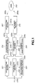
- FIG. 1 is a schematic block diagram of a preferred embodiment of broadcast signal processing device according to the invention.
- the broadcast signal processing device is adapted to receive an input signal 200a that can contain a video signal, an audio signal, a control signal and a program guide signal.
- the input signal 200a may be a signal that is received by way of a ground wave broadcasting system, a satellite broadcasting system, a cable broadcasting system or a telephone network or reproduced from some other recording device that has recorded the signal in advance.
- the video signal and the audio signal take a major part of the broadcast signal and contain the signals of a program itself and one or more than one CMs.
- the control signal includes information on the broadcasting mode, the time slot of broadcasting the program, the frequency of the wave or the channel to be used for the transmission of the signal.
- the program guide signal contains data related to the video signal and the audio signal when the signals are received in the case of digital broadcasting or by way of a telephone network. While it is assumed that the signals are those of a single broadcast program, the present invention is also applicable to signals that are input simultaneously by way of a plurality of channels.
- the CM detecting section 202 detects at least the start time of each CM (to be referred to as CM start time hereinafter) and the length of the CM section (to be referred to as CM length hereinafter from the input signal 200a containing the video signal, audio signal, control signal and the program guide signal and outputs a CM detection signal 202a indicating the CM start times and the CM lengths.
- CM start time the start time
- CM length of the CM section to be CM length of the CM section
- the operation of the CM detecting section 202 will be described in greater detail hereinafter along with the CM start times and the CM lengths.
- the CM detection signal 202a detected by the CM detecting section 202 is then sent to the CM extracting section 201 and the CM characteristics extracting section.
- the CM extracting section 201 extracts signal 201a that corresponds to the CM sections out of the input signal 202a on the basis of the CM detection signal 202a supplied from the CM detecting section 202. More specifically, the CM extracting section 201 extracts the signal sections corresponding to the CM sections as defined respectively by the CM start times and the CM lengths indicated by the CM detection signal 202a fed from the CM detecting section 202 and outputs CM part signals corresponding to the respective CM sections and containing video signals, audio signals, control signals and program guide signals respectively. The CM part signals 201a are sent to the CM recording section 205.
- the CM extracting section 201 is adapted to absorb the delay by using a temporary storage such as a magnetic recording device that is internally or externally provided.
- the CM recording section 205 is in fact a device for recording and reproducing signals by using a magnetic tape, a magnetic disc, an optomagnetic disc, a recordable optical disc and/or a semiconductor memory.
- the CM recording section 205 Upon receiving the CM part signals 201a (including the video signals, the audio signals, the control signals and the program guide signals corresponding to the CM sections), the CM recording section 205 records the CM part signals 201a.
- FIG. 2 is a schematic block diagram of a subset of the embodiment including only the CM extracting section 201, the CM recording section 202 and the CM recording section 205 and FIG. 3 is a flow chart of the operation of the subset of FIG. 2.
- the input signal 200a is stored in the internal or external temporary storage by the CM extracting section 201 in step S221.
- the CM detecting section 202 of the above subset detects the CM start times and the CM lengths of the CM sections. More specifically, the CM detecting section 202 detects each CM section out of the input signal 200a in Step S222 and then processing operation proceeds to Step S223 when it is determined that the detected section is a CM section but to Step S225 when it is determined that the detected section is not a CM section.
- Step S223 the CM extracting section 201 extracts the signal 201a containing the video signal, the audio signal, the control signal and the program guide signal of the detected CM section. Then, in Step S224, the CM recording section 205 stores the extracted signal.
- Step S225 the signals temporarily stored by the CM extracting section 201 is discarded and the processing operation returns to Step S220 to repeat the above steps.
- the CM characteristics extracting section 203 extracts CM characteristics out of the input signal 200a on the basis of the CM detection signal 202a fed from the CM detecting section 202. More specifically, the CM characteristics extracting section 203 extracts the characteristic values (representing some or all of the characteristics as CM as will be described hereinafter) of each of the signal parts contained in the CM detection signal 202a fed from the CM detecting section 202 and corresponding to the CM sections as defined by the CM start times and the CM lengths and outputs the characteristic values 203a to the CM recording section 205.
- the characteristic values representing some or all of the characteristics as CM as will be described hereinafter
- the CM characteristics extracting section 203 is adapted to absorb the delay by using a temporary storage such as a magnetic recording device that is internally or externally provided.
- the temporary storage of the CM characteristics extracting section 203 may share the temporary storage of the CM extracting section 201.
- the characteristic values for characterizing each of the CMs are extracted from the video signal and the audio signal. Part or all of the physical values of each CM including the amplitude characterizing value, the spectrum characterizing value, the linear prediction coefficient, the brightness histogram, the color histogram, the average luminance the luminance difference energy, the number of cut changes and the number of each cut change may be used for the purpose of the invention. These characteristic values shows a pattern that is identical to a CM and but different from that of some other CM so that they can be used to characterize the CM.
- the processing frame is the processing unit having a predetermined time length, which is typically 250ms.
- the number of frames corresponding to the length of a CM section is expressed by N as shown in (c) of FIG. 4.
- the amplitude characteristic value A[n] of processing frame n is the value of the mean square of the audio signals in frame n and obtained by means of formula (1) below.
- the computation is carried out by typically using FFT or linear prediction analysis.
- the operation of discretization of frequency can be reduced to a linear one or non-linear one that uses octave as unit of operation by rediscretizing k in formula (2).
- the linear prediction coefficient P[k;n] of processing frame n can be computationally determined by using an LPC algorithm such as the one shown in Linear Prediction of Speech (Markel et al., Springer Verag, 1978).
- k 0, ..., K-1 denotes the number for the linear prediction coefficient and K denotes the degree of prediction.
- the luminance histogram H 1 [q;n] of processing frame n is the luminance histogram of the video signals of frame n.
- q 0, ..., Q-1 denotes the index number of the luminance slot and Q denotes the number of slots of the histogram.
- the color histogram H c [q;n] of processing frame n is the intensity histogram of each color of the signal of frame n.
- q 0, ..., Q-1 denotes the index number of the color and intensity slot and Q denotes the number of slots of the histogram.
- the average luminance B[n] of processing frame n is that of the video signals in processing frame n and determined by formula (3) below.
- the luminance difference energy D[n] of processing frame n is the interpixel difference energy of adjacent video frames and typically determined by formula (4) below.
- the inter-pixel difference may be replaced by the difference in the average luminance of all the images or the inter-block difference, using blocks of 8 ⁇ 8 pixels or 16 ⁇ 16 pixels for horizontal direction ⁇ vertical direction.
- the number of cut changes C[n] of processing frame n is the number of the frames where the pixel difference energy between adjacent video frames exceeds a predetermined threshold value in the processing frame n and determined by formula (5) below; where Count b a (f) is a function for showing the number of times where the requirement of evaluation formula f is satisfied and D thsd is a predetermined threshold value for the luminance difference energy.
- the time of each cut change can be determined in terms of frame number n that satisfies the requirement of C[n] > 0.
- the number of cut changes for all the CM section can be determined as the total sum of C[n].
- the CM characteristics extracting section 203 detects all or part of the above described characteristic values for each CM section. Therefore, the characteristic values that characterizes the CM section is expressed by vector V defined by formula (6) below.
- V (A, F, P, H l , H c , B, D, C)
- V (A[n], F[k;n], P[k;n], H l [n], H c [n], B[n], D[n], C[n])
- the characteristic values described above and extracted by the CM characteristics extracting section 203 are then stored in the CM recording section 205 with the signal of the CM section (including video signal/audio signal/control signal/program guide signal) for the CM section extracted by the CM extracting section 201, which is described earlier.
- FIG. 5 is a schematic block diagram of a subset of the embodiment including the CM extracting section 201, the CM detecting section 202, the CM characteristics extracting section 203 and the CM recording section 205 and FIG. 6 is a flow chart of the operation of the subset of FIG. 5. Note that the steps of the flow chart of FIG. 6 that are same as those of the flow chart of FIG. 3 are denoted respectively by the same step numbers and will not be described any further. Therefore, only the steps relating to the CM characteristics extracting section 203 will be described below.
- Step S220 where the video signal, the audio signal, the control signal and the program guide signal of the input signal 200a are sequentially input
- the processing operation proceeds to Step S231, where the input signal 200a is temporarily stored in the internal or external temporary storage of the CM characteristics extracting section 203.
- Step S233 it is determined in Step S222 that the detected section is a CM section
- the processing operation proceeds to Step S235 if it is determined in Step S222 that the detected section is not a CM section.
- the CM characteristics extracting section 203 extracts characteristic values of the CM section out of the video signal, the audio signal, the control signal and the program guide signal of the CM section and the extracted characteristic values are stored in the CM recording section 205 in Step S234.
- Step S235 the signals temporarily stored in the CM characteristics extracting section 203 are discarded, and returns to Step S220 to repeats the above steps.
- the CM part signals 201a (including the video signals, the audio signals, the control signals and the program guide signals) of the CM section stored in the CM recording section 205 and the characteristic values 203a of the CM section are read out of the CM recording section 205 and sent to the CM index generating section 206 and the CM viewing section 208.
- the CM index generating section 206 generates information to be used as indexes for the CM on the basis of the CM part signals 201a and the characteristic values 203a fed from the CM recording section 205 and sends the information 206a (to be referred to as CM index information hereinafter) to the CM viewing section 208.
- the CM index information 206 a may typically be information showing the starting image, the cut point image, the cut point video image, the starting sound and/or the ending sound of the CM, which will be described below.
- CM index information 206a will be discussed below.
- the starting point image is the image at the very start of the CM section and used as part of the index information.
- the cut point image is the image of a cut point of the CM section and used as part of the index information. Since a cut point belongs to a processing frame whose characteristic value C[n] is greater than 0, the image of the time is used. While a CM section normally has a plurality of cut points, only a single image that may be the image of the first cut point or that of the last cut point as selected according to a predetermined criterion is used as the cut point image.
- the cut point video image is obtained by connecting the images of the cut points of the CM section to produce a video image, which is then used as part of the index information. Since a CM section normally has a plurality of cut points, a short video image is generated by connecting all the images of all the cut points.
- the starting sound is a sound that lasts for a predetermined period of time, e. g., 2 seconds, from the very start of the CM section and used as part of the index information. Since CMs often have a short characteristic sound at the very start thereof, it is useful to utilize the starting sound as a CM index.
- the ending sound is a sound that lasts for a predetermined period of time, e. g., 2 seconds, until the very end of the CM section and used as part of the index information. Since CMs often have a sound and an image specific to a particular product or a particular company or some other organization, it is useful to utilize the ending sound as a CM index.
- the CM part signals 201a and the characteristic values 203a of the CM section from the CM recording section 205 are supplied to the CM viewing section 208 along with the CM index information 206a from the CM index generating section 206.
- the CM viewing section 208 includes a display processor 801 and a display section 802.
- the display section 802 typically comprises a display device such as a CRT (cathode ray tube) or a liquid crystal monitor and a loudspeaker and is adapted to provide the user with images and sounds.
- a display device such as a CRT (cathode ray tube) or a liquid crystal monitor and a loudspeaker and is adapted to provide the user with images and sounds.
- the display processor 801 of the CM viewing section 208 is also fed with the user selected information 207a generated by the CM selecting section 207 according to the selecting instruction 209a of the user 209.
- the user 209 will view (208a) the CM index images, or the images and the icons, displayed on the display section 802 and issues a selecting instruction 209a to the CM index images, or the images and the icons, displayed on the display section 802 typically by means of a pointing device which may be a mouse, a remote commander or a touch panel.
- the CM selecting section 207 generates user selection information 207a corresponding to the user's selecting instruction 209a.
- the generated user selection information 207a is sent to the display processor 801 of the CM viewing section 208.
- the display processor 801 receives the CM index information 206a and the recording section reproduced signal 205a (particularly, video/audio signal sections) along with the user selection information 207a from the CM selecting section 207 and operates to display information to the user.
- the display processor 801 may typically comprise a processor and software.
- FIG. 7 showing a typical image of the display section 802.
- the display processor 801 firstly arranges CM index images, or video images 810, on a plurality of CMs according to the CM index information 206a typically as a single scene and displays it on the display section 802 as shown in FIG. 7.
- Each of the CM index images, or the video images 810 may be the starting point image or the cut point video image of the corresponding CM. If the number of CMs (the CM index images or the video images 810) is large, they may be arranged in two or more than two scenes.
- the display processor 801 also arranges icons 811 through 814 to be used by the user to input his or her instructions to the CM selecting section 207 in a scene along with the CM index images or the video images 810 on the display section 802. In the instance of FIG. 7, a total of twelve CM index images or the video images 810 are displayed in a single scene along with a CM reproduction icon 811, a sound reproduction icon 812, a preceding page icon 813 and a succeeding page icon 814
- the display processor 801 When a scene as shown in FIG. 7 is displayed and the display processor 801 receives user selection information 207a from the CM selecting section 207, the display processor 801 changes the display according to the user selection information 207a. More specifically, if the user 209 selects one or more than one CM index images or the video images by way of the CM selecting section 207, the display processor 801 may highlight the selected CM index images or the video images 810.
- the display processor 801 carries out a processing operation that corresponds to the selected icon. If, for example, the CM reproduction icon 811 is selected by the user selection information 207a, the display processor 801 reproduces the image and the sound of the CM that is already selected from the CM index images or the video images 810. If the sound reproduction icon 812 is specifically selected by the user selection information 207a, the display processor 801 reproduces the starting sound, the ending sound or the entire sound of the CM.
- the display processor 801 displays the CM index images or the video images 810 of the immediately preceding page on the display screen. If, on the other hand, the succeeding page icon 814 is selected by the user selection information 207a, the display processor 801 displays the CM index images or the video images 810 of the immediately succeeding page (that are not viewed by the user) on the display screen.
- FIG. 8 is a schematic block diagram of a subset of the embodiment including the CM recording section 205, the CM index generating section 206, the CM viewing section 208 and the CM selecting section 207.
- FIG. 9 is a flow chart of the operation of the subset of FIG. 8, that of the CM viewing section 208 in particular.
- the CM viewing section 208 specifies the CMs of the first page in Step S240 and obtains the video signals/audio signals of the CMs of the first page in Step S241. Then, CM index information 206a is generated in Step S242 by the CM index generating section 206.
- Step S243 the display processor 801 of the CM viewing section 208 generates a scene to be displayed on the display screen according to the CM index information 206a and drives the display section 802 to display the scene.
- Step S244 the display processor 801 waits for the input of a user instruction (user selection information 207a), while displaying the scene.
- the display processor 801 selects the CM index image or the video image 810 specified by the user selecting information 207a in Step S245. Then, the display processor 801 regenerates the scene highlighting the CM index image or the video image 810 and causes the display section 802 to display the highlighted scene as in Step S243 and subsequently waits for the input of an instruction by the user 209 as in Step S244.
- the display processor 801 If the user selection information 207a specifies the CM reproduction icon 811, the display processor 801 reproduces in the CM recording section 205, the video signal and the audio signal of the CM corresponding to the CM index image or the video image 810 already specified by the user selection information 207a, in Step S246. Then, the display processor 801 regenerates the scene corresponding to the reproduced video signal and causes the display section 802 to display the scene as in Step S243 and subsequently waits for the input of an instruction by the user 209 as in Step S244.
- the display processor 801 If the user selection information 207a specifies the sound reproduction icon 812, the display processor 801 reproduces in the CM recording section 205, the audio signal of the starting sound, the ending sound or all the sound of the CM corresponding to the CM index image or the video image 810 already specified by the user selection information 207a, in Step S247. Then, the display processor 801 drives the loudspeaker to output the sound of the reproduced audio signal as in Step S243 and subsequently waits for the input of an instruction by the user 209 as in Step S244.
- the display processor 801 reproduces in the CM recording section 205, the video signals and the audio signals of the CMs corresponding to the CM index images or the video images 810 of the immediately preceding page, in Step S248. Then, the display processor 801 drives the display section 802 to display the images corresponding to the reproduced video signals as in Step S243 and subsequently waits for the input of an instruction by the user 209 as in Step S244.
- the display processor 801 reproduces in the CM recording section 205, the video signals and the audio signals of the CMs corresponding to the CM index images or the video images 810 of the immediately succeeding page, in Step S249. Then, the display processor 801 drives the display section 802 to display the images corresponding to the reproduced video signals as in Step S243 and subsequently waits for the input of an instruction by the user 209 as in Step S244.
- the characteristic vector V of each CM recorded in the CM recording section 205 is sent to the characteristics comparing section 204 as signal 205b.
- the characteristics comparing section 204 reads out the characteristic vector V of each CM recorded in the CM recording section 205 by means of a reading control signal 204a.
- the characteristics comparing section 204 determines by comparison if the CM is the right CM or not by means of the characteristic vector V i of the CM read out from the CM recording section 205.
- "i" denotes the index (the variable of index) discriminating the individual CMs.
- the characteristics comparing section 204 compares the characteristic vectors V i and V j of two CMs in a manner as shown below.
- the characteristics comparing section 204 carries out the comparing operation for all the CMs stored in the CM recording section 205 and removes either one of the two CMs that are determined to be same from the CM recording section 205. As a result, all the duplicate signals of CMs stored in the CM recording section 205 will be removed.
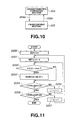
- FIG. 10 is a schematic block diagram of a subset of the embodiment including the CM recording section 205 and the characteristics comparing section.
- FIG. 11 is a flow chart of the operation of the subset of FIG. 10, that of the characteristics comparing section 204 in particular.
- the characteristics comparing section 204 sets the variable i of said index to 0 in Step S250 and then sets the variable j of said index to i+1.
- the characteristics comparing section 204 carries out computations for the evaluation function J(i,j) on the basis of the characteristic vectors V i and V j and compares it with a predetermined threshold value J thsd in Step S252. If the value of the function J(i,j) is lower than the threshold value J thsd (Yes), the two CMs are determined to be same and the CM represented by the characteristic vector V j is removed from the CM recording section 205 in Step S253. If, on the other hand, the value of the function J(i,j) is not lower than J thsd (No), the two CMs are determined to be different from each other and the processing operation proceeds to Step S254.
- Step S254 the characteristics comparing section 204 checks if the value of j corresponds to the last CM number among the CMs to be compared or not. If it is determined in Step S254 that the value of j does not correspond to the last CM member (No), j is incremented in Step S255 and the processing operation returns to Step S252, where J(i,j) is compared with the threshold value once again. If, on the other hand, it is determined in Step S254 that the value of j corresponds to that last CM member (Yes), it is determined in Step S256 if i corresponds to the last CM number or not.
- Step S256 If it is determined in Step S256 that the value of i does not correspond to the last CM number (No), i is incremented in Step S257 and the processing operation returns to Step S251 to set j once again. If, on the other hand, it is determined in Step S256 that the value of i corresponds to the last CM number (Yes), the processing operation is terminated there.
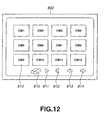
- FIG. 12 schematically illustrates a scene displayed on the display section 802 and containing an additional retrieval icon 815.
- the operations of the CM recording section 205, the characteristics comparing section 204, the CM viewing section 208, the CM index generating section 206 and the CM selecting section 207 will be described by referring to the illustrated image of FIG. 12.
- the CM selecting section 207 As the retrieval icon 815 is specified by the user 209, the CM selecting section 207 generates user selection information 207a corresponding to the user's selection and transmits the user selection information 207a to both the CM viewing section 208 and the characteristics comparing section 204.
- the characteristics comparing section 204 retrieves the CM having characteristics whose values partially agree with those of the CM that is already selected in the CM index image or the video image 810.
- the characteristics comparing section 204 compares the characteristic values of the CMi with the characteristic values of the CMj that is recorded in the CM recording section 205.
- the characteristics comparing section 204 firstly carries out computations for the evaluation function J'(i,j) of the CM part section, using formula (10) below; where N s denotes the first processing frame number of the CM part section to be compared and N e denotes the last processing frame number of the CM part section to be compared.
- the characteristics comparing section 204 compares the evaluation function J'(i,j) with the predetermined threshold value J' thsd and determines that they do not agree with each other when the former is greater than the latter value but they do when the former is not greater than the latter.
- the evaluation function J'(i,j) to be used for comparing characteristics values may alternatively be defined by formula (11) below; where N w denotes the span to be used for retrieving agreeing parts whose characteristic values agree with each other and s denotes the index number that is used for shifting the span for retrieving partially agreeing parts from the beginning to the end of the CM section. Min s () denotes the smallest value of all the values of s. It will be effective to use only the sound-related characteristic values A[n], F[k;n] and P[k;n] excluding the image-related characteristic values H 1 [n], H c [n], B[n], D[n] and C[n] from the vector [n].
- CMs that partly agree with each other For example, CMs containing a same piece of background music may be retrieved. If the CMs of a particular product or a particular company or some other organization are designed to provide a sense of continuation, they are often made to contain a same piece of background music in order to make the viewers have a feeling of sameness of similarity. Therefore, the function can be an effective evaluation function to be used for retrieving CMs that are designed to provide a sense of continuation.
- the evaluation functions J(i,j) and J'(i,j) may be referred to as similarity of two CMs.
- the audio and video signals of the CM retrieved from the CM recording section 205 are then sent to the CM viewing section 208 as recording section reproduced signal 205a.
- the index generating section 206 generates index information on the CMs whose characteristic values agree with each other and transmits the generated index information 206a to the CM viewing section 208.
- the CM viewing section 208 can display the image of the retrieved CM and/or reproduce the sound of the CM.
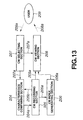
- FIG. 13 is a schematic block diagram of a subset of the embodiment including the CM recording section 205, the characteristics comparing section 204, the CM index generating section 206, the CM viewing section 208 and the CM selecting section 207.
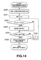
- FIG. 14 is a flow chart of the operation of the subset of FIG. 13. It will be appreciated that the flow chart of FIG. 14 comes immediately after the flow chart of FIG. 9.
- the characteristic comparing section 204 sets the index variable i to the value of the index of the selected CM in Step S260 and then sets the index variable j to 0 in Step S261.
- the characteristics comparing section 204 carries out computations for the evaluation function J'(i,j) in Step S262, using the characteristic vectors V i and V j , and compares the obtained value with the predetermined threshold value J' thsd . If it is determined that the obtained value is not greater than the threshold value J' thsd (Yes), the CM is judged to be a similar CM and the CM represented by the characteristic vector V j is marked in Step S263. If, on the other hand, it is determined that the obtained value is greater than the threshold value J' thsd (No), the CM is judged to be not a similar CM and the processing operation proceeds to the next step, or Step S294.
- Step S294 the characteristics comparing section 204 checks if the value of j corresponds to the last CM number among the CMs to be compared or not. If it is determined in Step S294 that the value of j does not correspond to the last CM member (No), j is incremented in Step S265 and the processing operation returns to Step S262, where J(i,j) is compared with the threshold value once again. If, on the other hand, it is determined in Step S266 that the value of j corresponds to that last CM member (Yes), all the marked CMs are specified collectively and the processing operation returns to Step S241 shown in FIG. 9, where signals of the specified CMs are retrieved from the CM recording section 205.
- This embodiment may alternatively be so arranged that the same CMs are not removed but stored and, the number of times and the clock times when same CMs are broadcast by retrieving them, detecting the agreement in all the CM sections.
- CM sections can be extracted from a broadcast signal along with characteristic values characterizing the CM sections so that the characteristic values may be stored. Then, it is possible to provide a data base device adapted to store only the CM sections of a program and their characteristic values without recording the program itself. Such characteristic values are useful when retrieving same CMs and/or similar CMs.
- any of the stored CMs can be displayed and viewed so that the viewer (user) can display a list of the stored CMs and reproduce and retrieve any CMs he or she wants.
- This functional feature is particularly useful when the viewer wants to detect and view a specific CM.
- any duplicate CMs can be removed from the stored CMs to save the storage capacity and eliminate the trouble of repeatedly viewing same CMs.
- CMs having a same end part it is possible to retrieve CMs having a same end part. Because CMs of a same product or a same company or some other organization normally contains a common image and a common sound, it is now possible to retrieve the CMs of a same product or a same provider can be retrieved and displayed with ease.
- CM detecting section 202 of FIG. 1 for detecting CMs out of a broadcast signal along with the start time and the length of each CM will be discussed below in greater detail.
- a characteristic value may or may not mean same as the term "characteristic” as used above from viewpoint of the CM characteristics extracting section 203 and the characteristics comparing section 204, although the both are used to express a characteristic aspect of a CM. Therefore, the two terms are used here indiscriminately.
- CMs that are broadcast through TV channels are prepared according to the specifications provided by the broadcasters particularly in terms of duration and hence "the time length (of a CM) is limited and cannot vary in many different ways". For instance, in Japan, all CMs have a duration of 15 seconds, 30 seconds or 60 seconds with very few exceptions.
- CM when a CM is broadcast, it is inserted into the stream of a TV program but prepared independently from the latter so that "the sound level falls (and becomes less audible)" and "the video signal is switched” inevitably before and after the CM.
- the expression that "the sound level falls” does not necessarily means that silence (or only a light noise) prevails there. In other words, the program can be switched to the CM or vice versa without a complete silence depending on the timing of the switch.
- CMs show the three characteristic aspects of CMs including "specified time lengths (few variations in time length)", “a low sound level” and “a switched image”. In other words, these are three “requirements” to be met by CMs. Therefore, these requirements will be referred to as “the three indispensable requirements” of CMs hereinafter.
- CM candidates or signal parts that will probably represents the corresponding respective CMs
- programs can also contain signal parts that do not represent any CM but meet the indispensable requirements, there still remains a risk of erroneously detecting parts of the program as CM candidates if only the indispensable requirements are used for detecting CMs.
- CMs show some or all of the following characteristic aspects due to of the nature of CMs, although there are obviously more exceptions if compared with the indispensable requirements.
- additional requirements occurs from the fact that CMs are produced by conforming to given specifications, that CMs are intended to achieve an advertising effect in a very short period of time and that CMs are subject to programming restrictions. Therefore, while the additional requirements are not deterministically reliable, they are effective when evaluating the probability of each CM.
- CM candidates (signal parts that probably represent respective CMs) are deterministically extracted from a TV broadcast signal on the basis of the "indispensable requirements” and selected according to statistic criteria that are based on the "additional requirements and any overlapping relationship of CMs is eliminated on the basis of the "logical requirement” to accurately detect CMs.
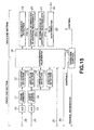
- FIG. 15 is a schematic block diagram of the CM detecting section, illustrating a possible first configuration thereof.
- the CM detecting section 202 comprises a front end section and a rear end section.
- the operation control section 23 determines if the broadcasting channel being detected is a channel where CMs are broadcast or not on the basis of channel information 1b that indicates the type of the channel and controls the components of FIG. 15 so as not to operate for detecting CMs if the channel is not used for broadcasting CMs.
- the video signal 2a, the audio signal 2b and the broadcasting mode signal 2c of the input signal 200a are input to the front end section.
- the time information 3a generated by a clock (not shown) is also fed to the front end section.
- the video signal 2a is digitized by A/D converter 10 and stored in frame memory 11, which is adapted to store at least video signals for two frames.
- the video signal read out from the frame memory 11 for each frame is then sent to cut change detector 12.
- the cut change detector 12 detects frames where the image changes abruptly (to be referred to as image change frames hereinafter) and frames showing a uniform luminance (to be referred to as uniform luminance frames hereinafter) on the basis of the video signal of each frame fed from the frame memory 11.
- the cut change detector 12 determines the difference of the square sums of the pixels of the temporally adjacent frames stored in the frame memory 11 and detects the temporally succeeding one of the two adjacent frames as image change frame where the image changes abruptly if the difference of the square sums exceeds a predetermined threshold value. Additionally, the cut change detector 12 determines the variance of luminance of the image of each of the frames stored in the frame memory 11 and detects the frame as a uniform luminance frame if the variance of luminance of the frame is under a predetermined threshold value.
- time interval separating two adjacent frames (about 30ms in the case of the NTSC system) does not agree with the frame period in the audio signal processing operation which will be described hereinafter, it is made to agree with the frame period by rediscretizing the time interval of two adjacent frames.
- the transversal size and the longitudinal size of a discretized video signal are X and Y respectively
- the transversal and longitudinal pixel numbers of each pixel are expressed by x, y respectively
- the image of the n-th frame is expressed by I n (x,y) while the image of the (n-1)-th frame that temporally immediately precedes the n-th frame is expressed by I n- 1 (x,y).
- the square sum D[n] of the difference of luminance of the pixels between the n-th frame and the (n-1)-th frame is obtained by formula (12) below and the variance of luminance of the n-th frame V[n] is expressed by formula (13) below.
- the detection output C[n] of the cut change detector 12 is expressed by formula (14) below; where D thsd is the predetermined threshold value for the square sum that is used when detecting an image change frame and V thsd is the predetermined threshold value for the variance of luminance that is used when detecting a uniform luminance frame.
- the detection output C[n] of the cut change detector 12 is then sent to characteristic value buffer 18 as a characteristic value of the video signal.
- the storage capacity and the amount of arithmetic operations can be reduced by dividing a frame image into small blocks and determining the difference of luminance for each block instead of treating the entire frame image at a same time.
- they can be reduced by determining the luminance histogram of each frame and subsequently the difference in the luminance histogram between two frames instead of determining the difference of luminance for each pixel.
- they can be reduced by determining the average luminance for each frame image and subsequently the difference in the average luminance between two frames.
- the accuracy of detection can be improved by determining the difference of luminance and that of color histogram for individual component colors such as R (red), G (green) and B (blue).
- the audio signal 2b is digitized by A/D converter 13 and stored in audio signal buffer 14.
- the audio signal buffer 14 has a storage capacity for storing at least 2-channel stereophonic audio signals for left (L) and right (R) for a predetermined time period T 1 (e.g., 30ms, which is to be referred to as a frame length hereinafter).
- the audio signals read out from the audio signal buffer 14 are then sent to amplitude detector 15, correlation detector 16 and spectrum detector 17
- T 2 e.g., 15ms, which is to be referred to as a frame period hereinafter
- the amplitude detector 15 calculates the mean square amplitude A[n] for the 2-channel audio signals for left and right in the n-th frame by using formula (15) below.
- the mean square amplitude A[n] obtained by, or the detection output of, the amplitude detector 15 is then sent to characteristic value buffer 18 as a characteristic value of the audio signal.
- the correlation detector 16 detects the correlation coefficient for the audio signal of each frame prior to the normalization, using the audio signals stored in the audio signal buffer 14 and also the short period energy to be used in the operation of normalization to be carried out downstream. If the audio signal buffer 14 stores 2-channel stereophonic signals for left and right, the correlation detector 16 detects the correlation coefficient for the 2-channel audio signals for left and right for a frame prior to the normalization out of the 2-channel stereophonic signal for left and right read out from the audio signal buffer 14 and also the short period energy to be used in the operation of normalization to be carried out downstream.
- the correlation detector 16 calculates the correlation efficient A LR [n] of the 2-channel audio signals for left and right for the n-th frame by using formula (16) below. It also calculates the left channel audio signal energy A LL [n] by using formula (17) and the right channel audio signal energy A RR [n] by using formula (18) as shown below.
- the detection output of the correlation detector 16 including the correlation coefficient A LR [n], the left channel audio signal energy A LL [n] and the right channel audio signal energy A RR [n] are sent to the characteristic value buffer 18 as so many characteristic values.
- the spectrum detector 17 calculates the short period spectrum by using the audio signals stored in the audio signal buffer 14. If the audio signal buffer 14 stores 1-channel stereophonic audio signals for left and right, the spectrum detector 17 calculates the short period spectrum out of the 2-channel stereophonic audio signals S L [m] and S R [m] for left and right read out from the audio signal buffer 14.
- formula (19) can be realized typically by means of an appropriate technique such as Fast Fourier Transform (FFT) or linear prediction analysis (LPC).
- FFT Fast Fourier Transform
- LPC linear prediction analysis
- the computational output, or the short period discrete spectrum F[k:n] of the spectrum detector 17 is sent to the characteristic value buffer 18 as a characteristic value for the audio signal.
- the broadcasting mode signal 2c is made to show a discretized value that conforms to the above described audio signal processing frame.
- the broadcasting mode signal 2c of the n-th frame may be made to show a numerical value B[n] as expressed by formula (20).
- the numerical value B[n] obtained by discretizing the broadcasting mode signal 2c is then sent to the characteristic value buffer 18 as a characteristic value of the TV broadcast signal.
- temporal signal 3a is also made to show a discretized numerical value T[n] that conforms to the audio signal processing frame and sent to the characteristic value buffer 18 as a characteristic value.
- the characteristic value buffer 18 stores the characteristic value G[n] shown in formula (21) below that includes the detection output C[n] from the cut change detector 12, the means square amplitude A[n] from the amplitude detector 15, the correlation coefficient A LR [n] and the audio signal energy values A LL [n] and A RR [n] from the correlation detector 16, the short period discrete spectrum F[k;n] from the spectrum detector 17, the discretized numerical value B[n] of the broadcasting mode signal 2c and the discretized numerical value T[n] of the temporal signal 3a for a predetermined period of time T 3 .
- the time T 3 is so determined that the buffer can store at least a CM and may typically be 80 seconds.
- G[n] ⁇ C[n], A[n], A LR [n], ALL[n], A RR [n], F[k;n], B[n], T[n] ⁇ (21)
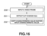
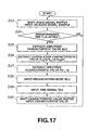
- the front end section of the CM detecting section 202 shown in FIG. 15 comprises the above described components from the A/D converter 10 to the characteristic value buffer 18. Now, the operation of the front end section will be described by referring to the flow charts of FIGS. 16 and 17. Note that Steps S30 through S32 in FIG. 16 are for the video signal 2a, whereas Steps S33 through S40 in FIG. 17 are for the audio signal 2b, the broadcasting mode signal 2c and the temporal signal 3a.
- Step S30 the front end section stores the video signal 2a for at least a frame that is digitized by the A/D converter 10 in the frame memory 11.
- the frame memory 11 is so designed as to handle a video signal 2a for a frame as a sample. Therefore, as the video signal 2a for a frame is input, the video signals 2a already stored in the frame memory 11 are shifted by a frame and the video signal 2a that was stored first in the frame memory 11 is pushed out as output.
- the front end section reads out the video signal 2a from the frame memory 11 and transmits it to the cut change detector 12 in Step S31, which cut change detector 12 by turn produces the detection output C[n] in a manner as described above.
- the front end section stores the detection output C[n] in the characteristic value buffer 18 in Step S32.
- the front end section inputs the audio signal 2b that is digitized by the A/D converter 13 into the audio signal buffer 14 and stores the audio signal 2b for at least a frame period T 2 in the audio signal buffer 14 in Steps S33 and S34.
- the audio signal buffer 14 is so designed as to handle an audio signal 2b for a frame period T 2 as a sample. Therefore, as the audio signal 2b for a frame period T 2 is input, the audio signals 2b already stored in the audio signal buffer 14 are shifted by a frame period T 2 and the audio signal 2b for a frame period T 2 that was stored first in the audio signal buffer 14 is pushed out as output.
- the front end section reads out the audio signal 2b stored in the audio signal buffer 14 and transmits it to the amplitude detector 15 in Step S35, which amplitude detector 15 by turn produces the means square amplitude A[n] in a manner as described above.
- the front end section transmits the audio signal 2b stored in the audio signal buffer 14 to the correlation detector 16 in Step S36, which correlation detector 16 by turn produces the correlation coefficient A LR [n] and the audio signal energy values A LL [n], A RR [n] in a manner as described above.
- the front end section transmits the audio signal 2b stored in the audio signal buffer 14 to the spectrum detector 17 in Step S37, which spectrum detector 17 by turn produces the short period discrete spectrum F[k;n] in a manner as described above.
- the front end section determines the discretized numerical value B[n] from the broadcasting mode signal 2c and the discretized numerical value T[n] from the temporal signal 3a in Step S38.
- the front end section stores the characteristic value G[n] including the detection output C[n] from the cut change detector 12, the root-mean-square amplitude A[n] from the amplitude detector 15, the correlation efficient A LR [n] and the audio signal energy values A LL [n], A RR [n] from the correlation detector 16, the short period discrete spectrum F[k;n] from the spectrum detector 17, the discretized numerical value B[n] of the broadcasting mode signal 2c and the discretized numerical value T[n] of the temporal signal 3a in the characteristic value buffer 18.
- n denotes the frame number of the characteristic value of each frame stored in the characteristic value buffer 18.
- the characteristic value of the most recent frame is expressed by G[0] and the value of n increases for an older frame so that, when the most recent frame is updated, the numbers of all the other frames and hence those of their characteristic values are shifted by 1).
- the characteristic values stored in the characteristic value buffer 18 are sent to CM candidate detector 19 on a frame by frame basis.
- the CM candidate detector 19 computationally detects the CM section, if any, of each frame on the basis of the above described "indispensable requirements" that are satisfied by almost all CMs.
- the characteristic value buffer 18 is so designed as to operates for inputting, shifting and outputting signals on the basis of a unit of a frame.
- the characteristic value buffer 18 is adapted to handle the characteristic value of a frame as a sample. Therefore, when the characteristic value of a frame is input, all the characteristic values already stored in the characteristic value buffer 18 are shifted by 1 frame and the characteristic value of a frame that was stored first in the characteristic value buffer 18 is pushed out as output.
- the CM candidate detector 19 checks if the characteristic value of a frame (a sample) meets the indispensable requirements including the sound level requirement, the video requirement and the time requirement in Steps S52 and S53. More specifically, the CM candidate detector 19 determines if the frame meets the indispensable requirements including the sound level requirement, the video requirement and the time requirement or not by comparing the means square amplitude A[0] of the first frame and the predetermined threshold value A thsd for square-root amplitude in Step S52 and checking if the detection output C[0] is equal to 1 or not in Step S53.
- Step S50 If it is determined by the CM candidate detector 19 that the means square amplitude A[0] does not exceed the predetermined threshold value A thsd for square-root amplitude and the indispensable requirements are met as a result of the processing operations of Steps S52 and S53, the frame is selected as CM candidate and the operation proceeds to Step S57 and on (Step S54 through S56 will be described hereinafter). If, on the other hand, it is determined by the CM candidate detector 19 that the means square amplitude A[0] exceeds the predetermined threshold value A thsd for square-root amplitude or the indispensable requirements are not met as a result of the processing operations of Steps S52 and S53, the frame is not selected as CM candidate and the operation returns to Step S50.
- the CM candidate detector 19 retrieves the CM starting frame n s in Step S57 and also the CM ending frame n e in Step S58 and then computationally determines the CM starting time T s in Step S59 and also the CM length W in Step S60.
- the CM candidate detector 19 After the retrieving and computing operations of Steps S57 through S60, the CM candidate detector 19 refers to the CM candidate table, which will be described hereinafter, in Step S61 and, if it finds a CM candidate whose CM starting time T s and CM length T w respectively agree with those of the detected CM candidate, it returns to Steps S54 through 56. If, on the other hand, it does not find any such a CM candidate, it adds the CM candidate as new one and returns to Steps S54 through S56.
- Step S54 through S56 When the processing operations of Steps S54 through S56 are conducted for all the time lengths, the CM candidate detector 19 returns to Step S50 and repeats the above steps for the next input.
- the CM starting frame n s refers to the frame number of the first frame whose means square amplitude A[n] exceeds the threshold value A thsd for square-root amplitude as viewed from the frame that meets the time requirements out of the frames expressed by n 1 , n 2 and n 3 toward the most recent frame.
- the CM ending frame n e refers to the frame number of the last frame whose means square amplitude A[n] does not exceed the threshold value A thsd for square-root amplitude as viewed from the 0-th frame toward the older frames.
- FIG. 19 shows an example that can be used for defining the indispensable requirements.
- [o] denotes a frame whose means square amplitude does not exceed the threshold value for square-root amplitude A thsd
- [x] denotes a frame whose root-mean-square amplitude exceeds the threshold value for square-root amplitude A thsd .
- the CM candidate detector 19 detects a CM candidate each time the characteristic value of a frame (sample) is input and, if a CM candidate is detected, it enters the candidate into the CM candidate table.
- FIG. 20 shows an example of CM candidate table.
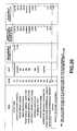
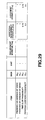
- the CM candidate table contains items including the starting time T s , the length T w , the characteristic values Q 1 through Q 11 as determined by the additional requirement computing unit 20, which will be described hereinafter, and the score R and the result of score judgment Z determined by the additional requirement determiner 21, which will also be described hereinafter.
- the starting time T s and the length T w are written at the stage of the CM candidate table 19a prepared by the CM candidate detector 19.
- the CM candidate table is used to describe and manage the starting time T s and the length T w obtained by the CM candidate detector 19, the characteristic values Q 1 through Q 11 computed by the additional requirement computing unit 20 and the score R and the result of score judgment Z determined by the additional requirement determiner 21.
- the CM candidate table is maintained until the entry is judged to be a CM or not a CM and is output as CM detection output 4a from the rule judging unit 22 if it is judged to be a CM but simply discarded if it is judged to be not a CM.
- the CM candidate table 19a carrying only the starting time T s and the length T w as described by the CM is then sent to the additional requirement computing unit 20.
- the additional requirement computing unit 20 extracts the characteristic values Q 1 through Q 11 from the candidate sections entered to the CM candidate table 19a, referring to the characteristic value buffer 18, in a manner as described below and adds them to the CM candidate table 19a to produce a CM candidate table 20a, which is then output to the additional requirement judging unit 21.
- FIG. 21 schematically illustrates how the characteristic values Q 1 through Q 11 are computationally determined by the additional requirement computing unit 20.
- the horizontal axes represent the frame number (corresponding to the discrete time).
- (a) shows the cut change detection output C[n] and (b) shows the discretized numerical value B[n] of the broadcast mode signal 2c, whereas (c) shows the short period discrete spectrum S[k,n] of the audio signal and (d)shows the root-mean-square amplitude A[n] of the audio signal.
- the part indicated by n 1 shows a CM candidate.
- the position indicated by CT shows the position where the cut change detection output C[n] is found to be equal to 1 (and hence where a cut change is detected).
- the part M indicates that it is in a broadcasting mode of some sort or another.
- S1, S2, S3 and S4 indicate that a spectrum component of some sort or another is there.
- AM indicates a change in the square-root amplitude and Q 1 through Q 11 indicates the respective positions where the characteristic values Q 1 through Q 11 are computationally determined by the additional requirement computing unit 20.
- the characteristic value Q 1 is the front break length, or the length of the low sound level section (to be referred to as "front break section") located immediately before a CM candidate section, where A[n] is successively less than a predetermined threshold value A thsd .
- the section between the corresponding dotted broken lines represents the front break length Q 1 .
- the characteristic value Q 2 is the rear break length, or the length of the low sound level section (to be referred to as "rear break section") located immediately after a CM candidate section, where A[n] is successively less than a predetermined threshold value A thsd .
- the section between the corresponding dotted broken lines represents the rear break length Q 2 .
- the characteristic value Q 3 is the front break minimal amplitude.
- the front break minimal amplitude Q 3 is the smallest value of A[n] in the front break section.
- the characteristic values Q 4 is the rear break minimal amplitude.
- the rear break minimal amplitude Q 4 is the smallest value of A[n] in the rear break section.
- the characteristic value Q 5 is the left/right correlation value.
- the left/right correlation value Q 5 is that of the 2-channel audio signals S L [m] and S R [m] for left and right. They can be computationally determined by using formula (25) below and A LR [n], A LL [n] and A RR [n] obtained by formulas (16) through (18).
- the characteristic value Q 6 is the average amplitude.
- the average amplitude Q 6 is the RMS of the amplitudes of the audio signals (root-mean-square amplitude) of the CM candidate section. This can be obtained by using formula (26) below.
- the characteristic value Q 7 is the number of cuts.
- the characteristic value Q 8 is the broadcasting mode.
- the broadcasting mode as used herein refers to the prevailing broadcasting mode in the CM candidate section. This is obtained by an operation of selecting the broadcasting mode Q 8 that appears most frequently in B[n] in [n s , n e ).
- the characteristic value Q 9 is the number of adjacent candidates.
- the number of adjacent candidates Q 9 indicates that if the sounded sections found before and after the CM candidate are also CM candidates or not.
- the characteristic value Q 9 is equal to [2] when a CM candidate is found before and after the CM candidate and [1] when a CM candidate is found only before or after the CM candidate. It is equal to [0] when no other CM candidate is found before and after the CM candidate.
- the operation of determining the number of adjacent candidates is realized by checking the CM candidate table.
- CM candidate that is immediately succeeding the CM candidate in question or not is determined by seeing if the sum of the starting time T s , the length T w and the rear break length Q 2 or (T s + T w + Q 2 ) agrees with the starting time (T' s ) of some other CM candidate or not.
- the front break length Q 1 or (T s - Q 1 ) agrees with the sum of the starting time T' s and the length T' w or (T' s + T' w ) of some other CM candidate or not.
- the characteristic values Q 10 and Q 11 are the front spectrum difference energy and the rear spectrum difference energy.
- the front spectrum difference energy and the rear spectrum difference energy Q 10 and Q 11 are used to quantize the change in the sound quality at the boundary of a CM and the program containing the CM or at the boundary of a CM and another CM. These are defined as the square sum of the difference between the average spectrum values of the opposite sides of the boundary and obtained by using formulas (27) through (32) below; and where N is the number of frames used for determining the average of spectrum values, n' e is the number of the ending frame of the sounded section found immediately before the CM candidate section (see FIG.
- n' s is the number of the starting frame of the sounded section found immediately after the CM candidate section
- S 1 [k] is the average spectrum immediately before the end of the sounded section that is found immediately before the CM candidate section
- S 2 [k] is the average spectrum immediately after the start of the CM candidate section
- S 3 [k] is the average spectrum immediately before the end of the CM candidate section
- S 4 [k] is the average spectrum immediately after the start of the sounded section that is found immediately after the CM candidate section
- S norm is an appropriate normalization constant.
- the above described additional requirement computing unit 20 additionally describes the characteristic values Q 1 through Q 11 that are determined in a manner as described above on the CM table 19a to produce the CM candidate table 20a as output.
- the CM candidate table 20a is sent output the additional requirement judging unit 21.
- the additional requirement judging unit 21 receives the CM candidate table 20a as input and calculates the score R for the CM candidate by performing a parameter transform on the characteristic values of the CM candidate typically, using a threshold function, and subsequently weighting the obtained values so that the CM candidate is judged to be a strong candidate when R exceeds a predetermined threshold value.
- the additional requirement judging unit 21 additionally describes the score R and the result of score judgment Z to the CM candidate table 20a to produce the CM candidate table 21a as output.
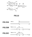
- FIG. 22 schematically illustrates the configuration of the additional requirement judging unit 21.
- the characteristic values Q 1 through Q L of the CM candidate table 21a are sent to respective function computing units 50 1 through 50 L , which perform transform operations by using respective parameter transform functions H 1 () through H L () and then obtain the products of the outcomes of the respective computations and respective weights W 1 through W L by means of respective weighting units 51 1 through 51 L .
- the characteristic values obtained as a result of the weighting operations, using the respective weighting units 51 1 through 51 L are added by summation adder 52 to obtain the score R.
- the score R output from the summation adder 52 is compared with a predetermined threshold value by score judging unit 53 and, if the score R exceeds a predetermined threshold value, an output telling that the CM candidate is judged to be a strong CM candidate is produced.
- the CM candidate that is determined by the score judging unit 53 so as to be not exceeding the threshold value is erased from the table.
- the parameter transform function H 1 () that is used by the function computing units 50 1 through 50 L may be a rectangular function, which is the most simple function.
- rectangular function Rect(x; t 1 , t 2 ) as shown in (b) of FIG. 23 may be used and t 11 and t 21 may be selected for the lower and upper limits of the reference value that is predetermined for each of the characteristic values. Then, if formula (34) is used, 1 is given when Q 1 is found within the scope of the reference value, whereas 0 is given when Q 1 if found out of the scope of the reference value.
- H 1 (Q 1 ) Rect (Q 1 ; t 1 , t 2 )
- a sigmoid function Sigm(x; t 1 , t 2 ) as expressed by formula (35) below may be used.
- FIG. 23 (c) schematically shows such smooth transitions.
- ⁇ 11 and ⁇ 21 are constants defining the profile of transition that are to be selected in advance typically by referring to the distribution of characteristic value.
- weight W 1 applied by the weighting units 51 1 through 51 L may be artificially selected in advance on the basis of the statistic properties of the characteristic values, it is also possible to select the weight by making the device learn known learning samples typically by means of a neural network (see, inter alia, Nakagawa, "Pattern Information Processing", Maruzen (1999).
- 1 represents any number between 1 and 11.
- the operation of score judgment of said judging unit 53 is performed by processing the threshold value for score R, using formula (36) below;
- Z Unit ® - t r )
- Unit (x) is a unit step function whose value is 1 when x > 0 and 0 when x ⁇ 0 as shown in (a) of FIG. 23 and t is a judgment threshold value that is predetermined or automatically selected as a result of a learning process.
- the rule judging unit 22 receives the CM candidate table 21a obtained as a result of the score judgment of the additional requirement judging unit 21 as input and produces the CM starting time and the CM length as final CM detection output 4a that is obtained as a result of a predetermined rule judging operation as will be described hereinafter.
- the rule judging unit 22 effects rule processing, thus selecting the most prominent CM candidate if there are two or more CM candidates at the same time. (The event that two or more CM candidates coexist shall be referred to as "competing relationship”.)
- Step S70 the rule judging unit 22 selects a CM candidate for judgment from the CM candidate table.
- the selected CM candidate is the oldest candidate in the CM candidate table that has survived for a predetermined time period T 4 , which is long enough for containing several CMs and may typically be 150 seconds.
- Step S71 the rule judging unit 22 checks the CM candidate table to see if any other CM candidate is found in the selected CM candidate section (which is the period from T s to T s + T w ). If it is determined in Step S71 that there is not any other CM candidate in the selected CM candidate section (No), the CM candidate is output as CM detection output and erased from the CM candidate table.
- Step S71 If, on the other hand, it is determined in Step S71 that there is another CM candidate in the selected CM candidate section (Yes), it is so judged that they are competing and the minimum length prioritizing rule is firstly applied to them in Step S72.
- the time section comprising a shorter CM candidate is prioritized among a number of time sections having a uniform length and comprising one or more than one CM candidates with different time lengths. More specifically, if there are a time section having a length of 30 seconds and comprising a single 30 seconds long CM candidate and a time section having a length of 30 seconds and comprising two 15 seconds long CM candidates, the 15 seconds long CM candidates are selected and the 30 seconds long CM candidate is discarded.
- the minimum length prioritizing rule will be described further by referring to FIG. 25 that illustrates an example.
- FIG. 25 shows a section where four CMs including CM1 through CM4 are successively broadcast, whereas (b) shows that eight CM candidates A through H are found in the CM candidate table.
- section G can be described by C and D, it is discarded and hence C is adopted.
- D is adopted as the CM candidate of D is subjected to judgment as shown in (f) of FIG. 25, there is no longer any competitor and it is no longer necessary to apply the rule. Therefore, D is adopted.
- A, B, C and D are selected from the time section as CM candidates. If there arises a competing situation to which this rule cannot be applied, all the CM candidates are left in the table and the processing operation will simply be terminated.
- Step S73 the rule judging unit 22 determines if the CM candidate being subjected to judgment is discarded or not as a result of the application of the minimum length prioritizing rule. If it is determined in Step S73 that the CM candidate being subjected to judgment is discarded (Yes), the rule judging unit 22 erases the candidate from the CM candidate table and returns to Step S70.
- Step S73 If, on the other hand, it is determined in Step S73 that the CM candidate being subjected to judgment is not discarded (No), the rule judging unit 22 checks the CM candidate table in Step S74 to see if there is any other CM candidate found in the time section of the CM candidate that is being subjected to judgment.
- Step S74 If it is determined in Step S74 that there is not any other CM candidate (No), the rule judging unit 22 outputs the CM candidate being subjected to judgment as detection output and erase it from the CM candidate table in Step S80. If, on the other hand, it is determined in Step S74 that there is at least another CM candidate (Yes), the rule judging unit 22 proceeds to Step S75.
- Step S75 the rule judging unit 22 applies the adjacency prioritizing rule to the CM candidate.
- the adjacency prioritizing rule if there are a plurality of CM candidates that are competing with each other, priority is given to the CM candidate having adjacent CM candidates that immediately precedes and succeeds it.
- the adjacency prioritizing rule will be described further by referring to FIG. 26, illustrating an example.
- FIG. 26 (a) shows that four CMs, or CM 11 through CM 14, are broadcast successively in a time section and (b) shows that there exist a total of six candidates, or candidates I through N, for the time section.
- the candidates M and N are selected as candidates simply because they incidently contains cut changes and low sound levels. It will be appreciated that, while such candidates are falsely selected for the time section, they survived the score judgment process for the additional requirements that is conducted to judge if the candidates are probably CMs or not because they contain CMs.
- the oldest CM candidate I is firstly subjected to judgment as shown in (c) of FIG. 26. While M competes with I, I has an adjacent candidate J but M does not have any adjacent candidate so that I is adopted and M is discarded. Then, the CM candidate J is subjected to judgment as shown in (d) of FIG. 26. While N completes with J, J has an adjacent candidate I and K but N does not have any adjacent candidate so that J is adopted and N is discarded. Subsequently, since the remaining CM candidates K, L do not have any competitor as shown in (e) and (f) of FIG. 26, both K and L are adopted without problem.
- I, J, K and L are selected as CM candidates from the time section of FIG. 26.
- Step S76 the rule judging unit 22 determines if the CM candidate being subjected to judgement is discarded or not as a result of the application of the adjacency prioritizing rule. If it is determined in Step S76 that the CM candidate being subjected to judgment is discarded (Yes), the rule judging unit 22 erases the candidate from the CM candidate table and returns to Step S70.
- Step S76 If, on the other hand, it is determined in Step S76 that the CM candidate being subjected to judgment is not discarded (No), the rule judging unit 22 checks the CM candidate table in the next Step S77 to see if there is any other CM candidate found in the time section of the CM candidate that is being subjected to judgment.
- Step S77 If it is determined in Step S77 that there is not any other CM candidate (No), the rule judging unit 22 outputs the CM candidate being subjected to judgment as detection output and erase it from the CM candidate table in Step S80. If, on the other hand, it is determined in Step S77 that there is at least another CM candidate (Yes), the rule judging unit 22 proceeds to Step S78. Where the rule judging unit 22 applies the score prioritizing rule to the CM candidate. With the score prioritizing rule, if the competing situation is not dissolved as a result of the application of the above rules, the candidate having a higher score R given as a result of the score judgment of the additional requirement judging unit 21 has priority. This score prioritizing rule is repeatedly applied until the competing situation is dissolved.
- the score prioritizing rule will be described by referring to FIG. 27, illustrating an example.
- FIG. 27 shows that four CMs, or CM 21 through CM 24, are broadcast successively in a time section and (b) shows that there exist a total of seven candidates, or candidates P through W, for the time section.
- the oldest CM candidate P is firstly subjected to judgment as shown in (c) of FIG. 27 and competing with U.
- the competing situation is not dissolved by applying the minimum length prioritizing rule and the adjacency prioritizing rule.
- the candidate Q having the highest judgment score of (1.9) is adopted and the candidate U that is competing with Q is discarded as shown in (f) of FIG. 27.
- Step S79 the rule judging unit 22 determines if the candidates being subjected to judgement is discarded or not as a result of the application of the score prioritizing rule. If it is determined in Step S79 that the CM candidate being subjected to judgment is discarded (Yes), the rule judging unit 22 erases the candidate from the CM candidate table and returns to Step S70.
- Step S79 If, on the other hand, it is determined in Step S79 that the CM candidate being subjected to judgment is not discarded (No), the rule judging unit 22 outputs the starting time and the length of the CM as CM detection output in Step S80 and erases the CM candidate from the CM candidate table before it returns to Step S70.
- CM detecting section 202 of this embodiment firstly deterministically extracts CM candidates from the program on the basis of the indispensable requirements that almost all CMs satisfy, selects CM candidates by statistically evaluating the characteristic values of each CM candidate on the basis of the additional requirements that are used to indicate probable CMs and then dissolves any overlapping relationship of candidates on the basis of the logical requirement in order to accurately detect CMs. While this embodiment is adapted to a video/audio recording apparatus adapted to currently prevalent analog TV broadcasting, it will be appreciated that the CM detecting section 202 is applicable to digital TV broadcasting. It will be appreciated that, when the embodiment is applied to radio broadcasting, the part of the CM detecting section 202 for processing video signals can be omitted.
- CM detecting section 202 of the embodiment of the present invention will be described below.
- FIG. 28 illustrates in detail the configuration of the second example of CM detecting section 202 of the embodiment of the invention.
- CM detecting section 202 is adapted to handle only the basic ones of the above described additional requirements. More specifically, of the additional requirements 1) through 14), 11) through 14) are not used for the CM detecting section 202 to simplify the configuration thereof. (preventing the intricacy)
- this second example of CM detecting section 202 comprises a front end section and a rear end section.
- FIG. 28 the components that are same as their counterparts of FIG. 15 are denoted respectively by the same reference symbols and will not be described any further.
- the sound source identifying unit 101 of the front end section receives a digitized and framed audio signal 2b as input and outputs the sound source name of the frame of the audio signal 2b.
- the sound source may be voice, music, voice and music and others. Any of the technologies illustrated in Kohchi et al., "Automatic Classification of Broadcast Sounds on the Basis of VQ distortions", Journal of the Society of Telecommunication Technology, DSP97-95/SP97-50, 43/48 (1998), Minami et al., "Video Indexing and Applications thereof Using Sound Information", Paper of the Society of Telecommunication Technology, Vol. J81-D-II, No. 3, 529/537 (1998) and the specification and the drawing of Abe's Japanese Patent Application Laid-Open No. 2001-024980 may be utilized for the purpose of the identifying the sound source of the input audio signal.
- a numerical value is assigned to each of the sound source names identified by the sound source identifying unit 101.
- the numerical value of each sound source is then input to the characteristic value buffer 18 as characteristic value U[n].
- the program category data or the program category identifying unit 102 arranged at the front end section is used to output the category name of the program being processed.
- the program category names that can be used for the purpose of the invention include news, drama, baseball and soccer.
- Program category data may be obtained from a TV program guide or a TV program table.
- program category data can be obtained automatically by way of Internet.
- the technology illustrated in the specification and the drawing of Abe's Japanese Patent Application Laid-Open No. 2001-024980 may be utilized for the purpose of the identifying the program category form the audio and video signals of the program being broadcast.
- a numerical value is assigned to each of the program category names identified by the program category data or the program category identifying unit 102 on a frame by frame basis.
- the numerical value of each program category is then input to the characteristic value buffer 18 as characteristic value W[n].
- the front end section has a configuration same as that of FIG. 15.
- the front end section is made to comprise the sound source identifying unit 101 and the program category data or the program category identifying unit 102 so that the characteristic values U[n] and W[n] obtained by them are stored in the characteristic value buffer 18.
- the characteristic value G[n] of formula (21) stored in the characteristic value buffer 18 is expanded to formula (37) below.
- the CM candidate tables 19a through 21a of this second example are extended in a manner as described below.
- the CM candidate tables 19a through 21a are extended in such a way that the characteristic values Q 12 through Q 15 to the above described characteristic values Q 1 through Q 11 as shown in FIG. 29. Note that, in FIG. 29, the characteristic values Q 1 through Q 11 are omitted and not shown.
- the CM probability data base 103 of the rear end section stores in advance the probability of transmission of each CM obtained as a function of time slot and the probability of transmission of each CM obtained as a function of program category and the elapsed time of program.
- the probabilities are read out from the CM probability data base 103 by referring to the current time and input to the additional requirement computing unit 20.
- the probability data stored in the CM probability data base 103 can be obtained by statistically processing the actually broadcast programs.
- the additional requirement computing unit 20 of the second example is extended to carry out the operations of computing the characteristic values Q 12 through Q 15 to the characteristic values Q 1 through Q 11 .
- the characteristic value Q 12 is obtained by checking if the CM candidate being examined contains one or more than one voice sections or not.
- the characteristic value Q 12 that shows if the CM candidate contains one ore more than one voice sections or not is determined by using formula (38) below.
- the characteristic value Q 13 is obtained by checking if the CM candidate being examined contains one or more than one music sections or not.
- the characteristic value Q 13 that shows if the CM candidate contains one ore more than one music sections or not is determined by using formula (39) below.
- the characteristic value Q 14 is the probability of occurrence of the CM in question as determined on the basis of the current time (time slot probability).
- the additional requirement computing unit 20 uses the probability of broadcasting the CM obtained from the CM probability data base 103 directly as the characteristic value Q 14 .
- the characteristic value Q 15 is the probability of occurrence of the CM in question as determined on the basis of program category of the current program and the elapsed time from the start of the program (program category probability).
- the additional requirement computing unit 20 uses the probability of broadcasting the CM obtained from the CM probability data base 103 directly as the characteristic value Q 15 .
- the arrangement of the CM detecting section 202 downstream to the additional requirement judging unit 21 is same as that the CM detecting section 202 of FIG. 15 except that the variables are extended to include the characteristic values Q 12 through Q 15 and therefore will not be described here any further.
- the CM detecting section 202 of this example can detect CMs on the basis of the sound sources of the broadcast signal, taking the current time and the program category into consideration.
- FIG. 30 is a schematic block diagram of the hardware components of the CM detecting section 202 of the embodiment that can be used for the purpose of the invention and illustrated in FIGS. 15 and 28.
- the A/D converter 40 has the function of the A/D converters 10 and 13 of FIGS. 15 and 28 and the memory 41 has the function of the frame memory 11 and that of audio signal buffer 14.
- the A/V processor, or DSP (digital signal processor) 42 has the functions of the cut change detector 112, the amplitude detector 15, the correlation detector 16, the spectrum detector 17, the sound source identifier 101 and so on and the memory 43 has the function of the characteristic value buffer 18.
- the processor 44 has functions of the CM candidate detector 19, the additional requirement computing unit 20, the additional requirement judging unit 21, the rule judging unit 22, the CM probability data base 103 and so on.
- Either the A/V processor, or the DSP (digital signal processor) 42 or the processor 44 may be made to have the function of the operation control section 23.
Landscapes
- Engineering & Computer Science (AREA)
- Signal Processing (AREA)
- Multimedia (AREA)
- Physics & Mathematics (AREA)
- Acoustics & Sound (AREA)
- Television Signal Processing For Recording (AREA)
- Testing, Inspecting, Measuring Of Stereoscopic Televisions And Televisions (AREA)
Abstract
Description

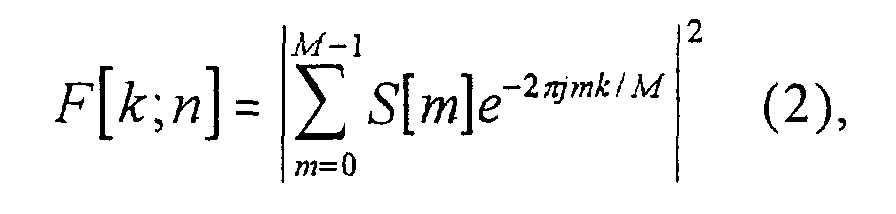







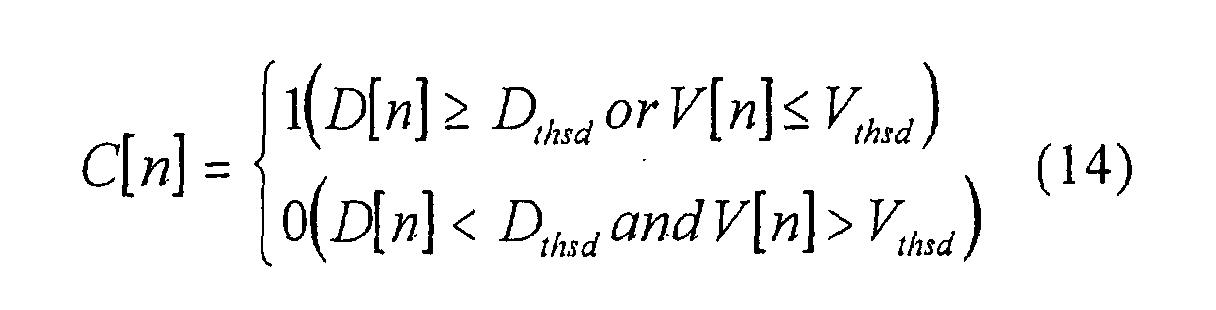


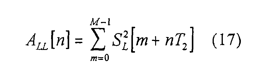

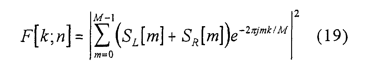
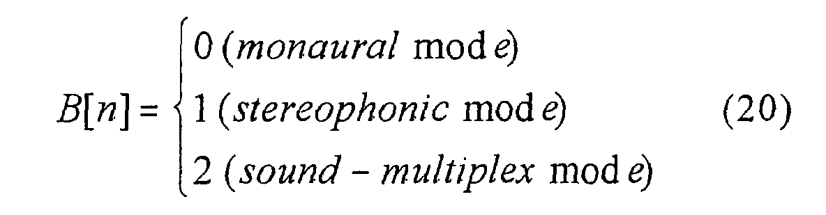


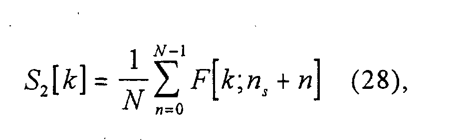


the characteristic values Q1 through Q11 that are determined in a manner as described above on the CM table 19a to produce the CM candidate table 20a as output. The CM candidate table 20a is sent output the additional requirement judging unit 21.




Claims (54)
- A signal processing device comprising:a first signal section detecting means for detecting a first signal section from an input signal including at least the first signal section and the remaining signal section on a time division basis;a first signal extracting means for extracting the signal in the first signal section from the input signal in accordance with a result of the detection by the first signal section; anda recording means for recording the extracted first signal.
- The signal processing device according to claim 1, further comprising a characteristic value extracting means for extracting the characteristic values characterizing the first signal from the extracted first signal, wherein said recording means records the characteristic values.
- The signal processing device according to claim 1, wherein said first signal section detecting means detects said first signal section from said input signal on the basis of a characteristic pattern of the signal appearing in said input signal at predetermined time intervals and a characteristic value showing the probability of the first signal.
- The signal processing device according to claim 1, wherein said first signal section detecting means detects said first signal section on the basis of predetermined guide information which is prepared corresponding to said input signal.
- The signal processing device according to claim 2, wherein said characteristic value characterizing said first signal is amplitude of the signal in the first signal section.
- The signal processing device according to claim 2, wherein said characteristic value characterizing said first signal is a spectrum of the signal in the first signal section.
- The signal processing device according to claim 2, wherein said characteristic value characterizing said first signal is a linear prediction coefficient of the signal in the first signal section.
- The signal processing device according to claim 2, wherein said characteristic value characterizing said first signal is a histogram of a predetermined component of the signal in the first signal section.
- The signal processing device according to claim 2, wherein said characteristic value characterizing said first signal is mean value of the predetermined component of the signal in the first signal section.
- The signal processing device according to claim 2, wherein said characteristic value characterizing said first signal is difference of the predetermined signal component of the signal in the first signal section.
- The signal processing device according to claim 2, wherein said characteristic value characterizing said first signal is the number of changes of the state of the signal in the first signal section.
- The signal processing device according to claim 2, wherein said characteristic value characterizing said first signal is the time of the change of the state of the signal in the first signal section.
- The signal processing device according to claim 1, further comprising:an index information extracting means for extracting information to be used as an index representing said recorded first signal; anda display means for displaying said extracted index information.
- The signal processing device according to claim 13, wherein said index information is an edited signal obtained by editing said first signal.
- The signal processing device according to claim 14, wherein said edited signal obtained by editing said first signal comprises a set of signals at the time when the state of said first signal changes.
- The signal processing device according to claim 14, wherein said edited signal obtained by editing said first signal comprises a signal representing a starting part of said first signal and/or a signal representing an ending part of said first signal.
- The signal processing device according to claim 13, wherein said index information extracting means extract the signal at a time when the state of said first signal changes.
- The signal processing device according to claim 2, further comprising a comparing means for comparing characteristic values respectively characterizing different first signals.
- The signal processing device according to claim 18, wherein said comparing means is detects agreement/disagreement of the first signals in a part of the section or in the entire section by comparing said characteristic values.
- The signal processing device according to claim 18, wherein said comparing means detects the degree of similarity of the first signals in a part of the section or in the entire section by comparing said characteristic values.
- The signal processing device according to claim 18, wherein said comparing means performs the comparing operation on a basis of the distance as determined by using a predetermined distance scale between vectors formed at least one of the amplitude of the signal in the first signal section, the spectrum of the signal in the first signal section, the linear prediction coefficient of the signal in the first signal section, the histogram of a predetermined component of the signal in the first signal section, the mean value of the predetermined component of the signal in the first signal section, the difference in the predetermined signal component of the signal in the first signal section, the number of changes in the state of the signal in the first signal section and the time of a change in the state of the signal in the first signal section.
- The signal processing device according to claim 13, further comprising:an index information specifying means for specifying desired index information from said displayed plurality of pieces of index information; anda retrieving means for retrieving the first signal corresponding to said specified index information.
- The signal processing device according to claim 2, further comprising:
a retrieving means for retrieving the first signal substantially agreeing with said first signal from said recording means, using said first signal in a part of the section or in the entire section or a characteristic value characterizing the first signal as retrieving condition. - The signal processing device according to claim 2, further comprising:
a retrieving means for retrieving the first signal substantially agreeing with said first signal from said recording means, using a part or all of said first signal or a characteristic value characterizing the first signal as retrieving condition. - The signal processing device according to claim 1, further comprising:
a measuring means for measuring the number of times and/or the hours of appearances of a same first signal. - The signal processing device according to claim 1, further comprising:
a measuring means for measuring the number of times and/or the hours of appearances of similar first signals. - A signal processing method comprising the steps of:detecting a first signal section from an input signal containing at least the first signal section and the remaining signal section on a time division basis;extracting the signal of the first signal section out of the input signal in accordance with to the result of the detection of the first signal section; andrecording the extracted first signal.
- The signal processing method according to claim 27, further comprising the steps of:extracting the characteristic values characterizing the first signal from the extracted first signal; andrecording the characteristic values.
- The signal processing method according to claim 27, wherein said first signal section detecting step is adapted to detect said first signal section from said input signal on the basis of a characteristic pattern of the signal appearing in said input signal at predetermined time intervals and a characteristic value showing the probability of the first signal.
- The signal processing method according to claim 27, wherein
said first signal section detecting step is adapted to detect said first signal section on a basis of predetermined guide information which is prepared to correspond to said input signal. - The signal processing method according to claim 28, wherein said characteristic value characterizing said first signal is amplitude of the signal in the first signal section.
- The signal processing method according to claim 28, wherein said characteristic value characterizing said first signal is a spectrum of the signal in the first signal section.
- The signal processing method according to claim 28, wherein said characteristic value characterizing said first signal is a linear prediction coefficient of the signal in the first signal section.
- The signal processing method according to claim 28, wherein said characteristic value characterizing said first signal is a histogram of a predetermined component of the signal in the first signal section.
- The signal processing method according to claim 28, wherein said characteristic value characterizing said first signal is mean value of the predetermined component of the signal in the first signal section.
- The signal processing method according to claim 28, wherein said characteristic value characterizing said first signal is difference of the predetermined signal component of the signal in the first signal section.
- The signal processing method according to claim 28, wherein said characteristic value characterizing said first signal is the number of changes of the state of the signal in the first signal section.
- The signal processing method according to claim 28, wherein said characteristic value characterizing said first signal is the time of the change of the state of the signal in the first signal section.
- The signal processing method according to claim 27, further comprising the steps of:extracting information to be used as an index representing said recorded first signal; anddisplaying said extracted index information.
- The signal processing method according to claim 39, wherein said index information is an edited signal obtained by editing said first signal.
- The signal processing method according to claim 40, wherein said edited signal obtained by editing said first signal comprises a set of signals at the time when the state of said first signal changes.
- The signal processing method according to claim 40, wherein said edited signal obtained by editing said first signal comprises a signal representing a starting part of said first signal and/or a signal representing an ending part of said first signal.
- The signal processing method according to claim 39, wherein said index information extracting step is adapted to extract the signal at a time when the state of said first signal changes.
- The signal processing method according to claim 28, further comprising a comparing step for comparing characteristic values respectively characterizing different first signals.
- The signal processing method according to claim 44, wherein said comparing step is adapted to detect the agreement/disagreement of the first signals in a part of the section or in the entire section by comparing said characteristic values.
- The signal processing method according to claim 44, wherein said comparing step is adapted to detect the degree of similarity of the first signals in a part of the section or in the entire section by comparing said characteristic values.
- The signal processing method according to claim 44, wherein said comparing steps is adapted to perform the comparing operation on the basis of the distance as determined by using a predetermined distance scale between vectors formed at least one of the amplitude of the signal in the first signal section, the spectrum of the signal in the first signal section, the linear prediction coefficient of the signal in the first signal section, the histogram of a predetermined component of the signal in the first signal section, the average value of a predetermined component of the signal in the first signal section, the difference in a predetermined signal component of the signal in the first signal section, the number of changes in the state of the signal in the first signal section and the time of a change in the state of the signal in the first signal section.
- The signal processing method according to claim 39, further comprising an index information specifying step for specifying desired index information from said displayed plurality of pieces of index information; and
a retrieving step for retrieving the first signal corresponding to said specified index information. - The signal processing method according to claim 28, further comprising a retrieving step for retrieving a first signal substantially agreeing with said first signal from said recording step, using said first signal in a part of the section or in the entire section or a characteristic value characterizing the first signal as retrieving condition.
- The signal processing method according to claim 28, further comprising a retrieving step for retrieving a first signal substantially agreeing with said first signal from said recording step, using a part or all of said first signal or a characteristic value characterizing the first signal as retrieving condition.
- The signal processing method according to claim 27, further comprising a measuring step for measuring the number of times and/or the hours of appearances of a same first signal.
- The signal processing method according to claim 27, further comprising a measuring step for measuring the number of times and/or the hours of appearances of similar first signals.
- The signal processing device according to claim 1, wherein said input signal comprises a video signal and/or an audio signal and said first signal covers a commercial message section.
- The signal processing method according to claim 27, wherein said input signal comprises a video signal and/or an audio signal and said first signal covers a commercial message section.
Applications Claiming Priority (2)
| Application Number | Priority Date | Filing Date | Title |
|---|---|---|---|
| JP2000132918A JP4332988B2 (en) | 2000-04-27 | 2000-04-27 | Signal processing apparatus and method |
| JP2000132918 | 2000-04-27 |
Publications (2)
| Publication Number | Publication Date |
|---|---|
| EP1150503A2 true EP1150503A2 (en) | 2001-10-31 |
| EP1150503A3 EP1150503A3 (en) | 2006-01-25 |
Family
ID=18641520
Family Applications (1)
| Application Number | Title | Priority Date | Filing Date |
|---|---|---|---|
| EP01110435A Withdrawn EP1150503A3 (en) | 2000-04-27 | 2001-04-27 | Signal processing device and signal processing method |
Country Status (3)
| Country | Link |
|---|---|
| US (1) | US7962007B2 (en) |
| EP (1) | EP1150503A3 (en) |
| JP (1) | JP4332988B2 (en) |
Cited By (2)
| Publication number | Priority date | Publication date | Assignee | Title |
|---|---|---|---|---|
| EP1858017A1 (en) * | 2006-03-29 | 2007-11-21 | Kabushiki Kaisha Toshiba | Image processing apparatus and file reproduce method |
| US20210240993A1 (en) * | 2018-06-05 | 2021-08-05 | Nippon Telegraph And Telephone Corporation | Device and method for detecting display of provided credit, and program |
Families Citing this family (24)
| Publication number | Priority date | Publication date | Assignee | Title |
|---|---|---|---|---|
| JP2002010237A (en) * | 2000-06-22 | 2002-01-11 | Sony Corp | Information transmitting / receiving system and method, information processing apparatus and method |
| US7525697B2 (en) * | 2002-07-15 | 2009-04-28 | Olympus Corporation | White balance processing apparatus and processing method thereof |
| US8312489B2 (en) * | 2005-02-23 | 2012-11-13 | Sony Corporation | CM searching method and apparatus, and CM-appendant information supplying method and apparatus |
| KR100772866B1 (en) * | 2006-02-21 | 2007-11-02 | 삼성전자주식회사 | Apparatus and method for synchronizing playback time of time shifted content with real time content |
| JP2008172498A (en) * | 2007-01-11 | 2008-07-24 | Sony Corp | Playback apparatus, playback method, and program |
| US8311390B2 (en) * | 2008-05-14 | 2012-11-13 | Digitalsmiths, Inc. | Systems and methods for identifying pre-inserted and/or potential advertisement breaks in a video sequence |
| KR101027159B1 (en) | 2008-07-28 | 2011-04-05 | 뮤추얼아이피서비스(주) | Target image detection device and method |
| US9386356B2 (en) | 2008-11-26 | 2016-07-05 | Free Stream Media Corp. | Targeting with television audience data across multiple screens |
| US9961388B2 (en) | 2008-11-26 | 2018-05-01 | David Harrison | Exposure of public internet protocol addresses in an advertising exchange server to improve relevancy of advertisements |
| US9154942B2 (en) | 2008-11-26 | 2015-10-06 | Free Stream Media Corp. | Zero configuration communication between a browser and a networked media device |
| US9986279B2 (en) | 2008-11-26 | 2018-05-29 | Free Stream Media Corp. | Discovery, access control, and communication with networked services |
| US8180891B1 (en) | 2008-11-26 | 2012-05-15 | Free Stream Media Corp. | Discovery, access control, and communication with networked services from within a security sandbox |
| US10334324B2 (en) | 2008-11-26 | 2019-06-25 | Free Stream Media Corp. | Relevant advertisement generation based on a user operating a client device communicatively coupled with a networked media device |
| US10567823B2 (en) | 2008-11-26 | 2020-02-18 | Free Stream Media Corp. | Relevant advertisement generation based on a user operating a client device communicatively coupled with a networked media device |
| US9026668B2 (en) | 2012-05-26 | 2015-05-05 | Free Stream Media Corp. | Real-time and retargeted advertising on multiple screens of a user watching television |
| US10880340B2 (en) | 2008-11-26 | 2020-12-29 | Free Stream Media Corp. | Relevancy improvement through targeting of information based on data gathered from a networked device associated with a security sandbox of a client device |
| US10977693B2 (en) | 2008-11-26 | 2021-04-13 | Free Stream Media Corp. | Association of content identifier of audio-visual data with additional data through capture infrastructure |
| US10631068B2 (en) | 2008-11-26 | 2020-04-21 | Free Stream Media Corp. | Content exposure attribution based on renderings of related content across multiple devices |
| US9519772B2 (en) | 2008-11-26 | 2016-12-13 | Free Stream Media Corp. | Relevancy improvement through targeting of information based on data gathered from a networked device associated with a security sandbox of a client device |
| US10419541B2 (en) | 2008-11-26 | 2019-09-17 | Free Stream Media Corp. | Remotely control devices over a network without authentication or registration |
| US8699855B2 (en) * | 2010-12-23 | 2014-04-15 | Echostar Technologies L.L.C. | User-selected interstitial media content recording |
| CN104182957B (en) * | 2013-05-21 | 2017-06-20 | 北大方正集团有限公司 | Traffic video information detecting method and device |
| CN104581396A (en) * | 2014-12-12 | 2015-04-29 | 北京百度网讯科技有限公司 | Processing method and device for promotion information |
| JP6850166B2 (en) * | 2017-03-17 | 2021-03-31 | 日本放送協会 | Video stream match judgment program |
Family Cites Families (24)
| Publication number | Priority date | Publication date | Assignee | Title |
|---|---|---|---|---|
| US4685003A (en) * | 1983-12-02 | 1987-08-04 | Lex Computing & Management Corporation | Video composition method and apparatus for providing simultaneous inputting and sorting of video source material |
| DE3915868C2 (en) * | 1989-05-16 | 1996-09-12 | Zeiss Carl Fa | UV-compatible dry lens for microscopes |
| JPH05205344A (en) | 1992-01-27 | 1993-08-13 | Mitsubishi Electric Corp | Video recording system |
| US5696866A (en) | 1993-01-08 | 1997-12-09 | Srt, Inc. | Method and apparatus for eliminating television commercial messages |
| US5579537A (en) | 1993-04-08 | 1996-11-26 | Digital D.J. Inc. | Broadcast system with associated data capabilities |
| US5966495A (en) * | 1993-05-12 | 1999-10-12 | Canon Kabushiki Kaisha | Recording and reproducing apparatus |
| US5343251A (en) * | 1993-05-13 | 1994-08-30 | Pareto Partners, Inc. | Method and apparatus for classifying patterns of television programs and commercials based on discerning of broadcast audio and video signals |
| US5594493A (en) | 1994-01-19 | 1997-01-14 | Nemirofsky; Frank R. | Television signal activated interactive smart card system |
| CN1312609C (en) * | 1995-04-08 | 2007-04-25 | 索尼公司 | editing system |
| US5751672A (en) * | 1995-07-26 | 1998-05-12 | Sony Corporation | Compact disc changer utilizing disc database |
| US5774664A (en) * | 1996-03-08 | 1998-06-30 | Actv, Inc. | Enhanced video programming system and method for incorporating and displaying retrieved integrated internet information segments |
| JPH09247612A (en) | 1996-03-12 | 1997-09-19 | Hitachi Ltd | Image signal handling method |
| JP3315879B2 (en) | 1996-10-25 | 2002-08-19 | 松下電器産業株式会社 | Image recording device and image reproducing device |
| US5948061A (en) * | 1996-10-29 | 1999-09-07 | Double Click, Inc. | Method of delivery, targeting, and measuring advertising over networks |
| JPH10224722A (en) | 1997-02-07 | 1998-08-21 | Sony Corp | Commercial scene detector and its detection method |
| JP3544105B2 (en) | 1997-09-26 | 2004-07-21 | 富士ゼロックス株式会社 | Received information recording device and received information recording method |
| US6698020B1 (en) * | 1998-06-15 | 2004-02-24 | Webtv Networks, Inc. | Techniques for intelligent video ad insertion |
| DE19828072A1 (en) * | 1998-06-24 | 1999-12-30 | Thomson Brandt Gmbh | Procedure for recording and playing back a broadcast program contribution |
| US6100941A (en) * | 1998-07-28 | 2000-08-08 | U.S. Philips Corporation | Apparatus and method for locating a commercial disposed within a video data stream |
| US6169542B1 (en) * | 1998-12-14 | 2001-01-02 | Gte Main Street Incorporated | Method of delivering advertising through an interactive video distribution system |
| JP3485029B2 (en) | 1999-06-10 | 2004-01-13 | 日本電気株式会社 | Program recording and playback system |
| JP4304839B2 (en) * | 2000-07-13 | 2009-07-29 | ソニー株式会社 | Video signal recording / reproducing apparatus and method, and recording medium |
| US6959143B2 (en) * | 2000-12-26 | 2005-10-25 | Eloda Inc. | Advertising extracting system |
| US20050028200A1 (en) * | 2003-08-01 | 2005-02-03 | Esteban Sardera | Media content navigation associated advertising |
-
2000
- 2000-04-27 JP JP2000132918A patent/JP4332988B2/en not_active Expired - Fee Related
-
2001
- 2001-04-26 US US09/843,629 patent/US7962007B2/en not_active Expired - Fee Related
- 2001-04-27 EP EP01110435A patent/EP1150503A3/en not_active Withdrawn
Cited By (3)
| Publication number | Priority date | Publication date | Assignee | Title |
|---|---|---|---|---|
| EP1858017A1 (en) * | 2006-03-29 | 2007-11-21 | Kabushiki Kaisha Toshiba | Image processing apparatus and file reproduce method |
| US20210240993A1 (en) * | 2018-06-05 | 2021-08-05 | Nippon Telegraph And Telephone Corporation | Device and method for detecting display of provided credit, and program |
| US12028573B2 (en) * | 2018-06-05 | 2024-07-02 | Nippon Telegraph And Telephone Corporation | Device and method for detecting display of provided credit, and program |
Also Published As
| Publication number | Publication date |
|---|---|
| JP2001313898A (en) | 2001-11-09 |
| JP4332988B2 (en) | 2009-09-16 |
| EP1150503A3 (en) | 2006-01-25 |
| US20020015105A1 (en) | 2002-02-07 |
| US7962007B2 (en) | 2011-06-14 |
Similar Documents
| Publication | Publication Date | Title |
|---|---|---|
| EP1150503A2 (en) | Signal processing device and signal processing method | |
| US7742680B2 (en) | Apparatus and method for processing signals | |
| KR100711948B1 (en) | Personalized Video Classification and Retrieval System | |
| CN101051514B (en) | Recording and reproducing device and recording and reproducing method | |
| US6928233B1 (en) | Signal processing method and video signal processor for detecting and analyzing a pattern reflecting the semantics of the content of a signal | |
| EP1584187B1 (en) | Real-time recording agent for streaming data from an internet | |
| US20050038661A1 (en) | Closed caption control apparatus and method therefor | |
| US7673320B2 (en) | Information transmission/reception system and method and information processing method and apparatus for automatic detection of data for commercial messages | |
| JP2004336507A (en) | Video processing apparatus and method, recording medium, and program | |
| US20100319015A1 (en) | Method and system for removing advertising content from television or radio content | |
| KR20050088490A (en) | Method and apparatus for similar video content hopping | |
| TW200402654A (en) | A system and method for providing user control over repeating objects embedded in a stream | |
| US20090279840A1 (en) | Image Digesting Apparatus | |
| US8325803B2 (en) | Signal processing apparatus, signal processing method, and program | |
| WO2004012447A1 (en) | Method of and system for controlling the operation of a video system | |
| JP4512969B2 (en) | Signal processing apparatus and method, recording medium, and program | |
| US8234278B2 (en) | Information processing device, information processing method, and program therefor | |
| JP4793929B2 (en) | AV apparatus having progress bar configuration information generation function with feature information | |
| US20070028256A1 (en) | Method and apparatus for facilitating program selection | |
| JPH08265660A (en) | Music management method and device | |
| JP4507351B2 (en) | Signal processing apparatus and method | |
| JP3617785B2 (en) | Broadcast system, information reference method thereof, and receiving apparatus | |
| CN121509783A (en) | Live broadcast segment generation methods, devices, media, electronic equipment and products | |
| WO2011041008A1 (en) | Method for removing advertising content | |
| KR20040070943A (en) | Method and system for offering channel for singing room using network and satellite |
Legal Events
| Date | Code | Title | Description |
|---|---|---|---|
| PUAI | Public reference made under article 153(3) epc to a published international application that has entered the european phase |
Free format text: ORIGINAL CODE: 0009012 |
|
| AK | Designated contracting states |
Kind code of ref document: A2 Designated state(s): AT BE CH CY DE DK ES FI FR GB GR IE IT LI LU MC NL PT SE TR |
|
| AX | Request for extension of the european patent |
Free format text: AL;LT;LV;MK;RO;SI |
|
| PUAL | Search report despatched |
Free format text: ORIGINAL CODE: 0009013 |
|
| AK | Designated contracting states |
Kind code of ref document: A3 Designated state(s): AT BE CH CY DE DK ES FI FR GB GR IE IT LI LU MC NL PT SE TR |
|
| AX | Request for extension of the european patent |
Extension state: AL LT LV MK RO SI |
|
| 17P | Request for examination filed |
Effective date: 20060602 |
|
| AKX | Designation fees paid |
Designated state(s): DE FR GB |
|
| 17Q | First examination report despatched |
Effective date: 20090424 |
|
| STAA | Information on the status of an ep patent application or granted ep patent |
Free format text: STATUS: THE APPLICATION IS DEEMED TO BE WITHDRAWN |
|
| 18D | Application deemed to be withdrawn |
Effective date: 20131101 |