EP1150288A2 - Optical recording medium - Google Patents
Optical recording medium Download PDFInfo
- Publication number
- EP1150288A2 EP1150288A2 EP01106919A EP01106919A EP1150288A2 EP 1150288 A2 EP1150288 A2 EP 1150288A2 EP 01106919 A EP01106919 A EP 01106919A EP 01106919 A EP01106919 A EP 01106919A EP 1150288 A2 EP1150288 A2 EP 1150288A2
- Authority
- EP
- European Patent Office
- Prior art keywords
- range
- film
- weight
- recording
- phase change
- Prior art date
- Legal status (The legal status is an assumption and is not a legal conclusion. Google has not performed a legal analysis and makes no representation as to the accuracy of the status listed.)
- Withdrawn
Links
Images



Classifications
-
- G—PHYSICS
- G11—INFORMATION STORAGE
- G11B—INFORMATION STORAGE BASED ON RELATIVE MOVEMENT BETWEEN RECORD CARRIER AND TRANSDUCER
- G11B7/00—Recording or reproducing by optical means, e.g. recording using a thermal beam of optical radiation by modifying optical properties or the physical structure, reproducing using an optical beam at lower power by sensing optical properties; Record carriers therefor
- G11B7/24—Record carriers characterised by shape, structure or physical properties, or by the selection of the material
- G11B7/241—Record carriers characterised by shape, structure or physical properties, or by the selection of the material characterised by the selection of the material
- G11B7/242—Record carriers characterised by shape, structure or physical properties, or by the selection of the material characterised by the selection of the material of recording layers
- G11B7/243—Record carriers characterised by shape, structure or physical properties, or by the selection of the material characterised by the selection of the material of recording layers comprising inorganic materials only, e.g. ablative layers
-
- G—PHYSICS
- G11—INFORMATION STORAGE
- G11B—INFORMATION STORAGE BASED ON RELATIVE MOVEMENT BETWEEN RECORD CARRIER AND TRANSDUCER
- G11B7/00—Recording or reproducing by optical means, e.g. recording using a thermal beam of optical radiation by modifying optical properties or the physical structure, reproducing using an optical beam at lower power by sensing optical properties; Record carriers therefor
- G11B7/007—Arrangement of the information on the record carrier, e.g. form of tracks, actual track shape, e.g. wobbled, or cross-section, e.g. v-shaped; Sequential information structures, e.g. sectoring or header formats within a track
-
- G—PHYSICS
- G11—INFORMATION STORAGE
- G11B—INFORMATION STORAGE BASED ON RELATIVE MOVEMENT BETWEEN RECORD CARRIER AND TRANSDUCER
- G11B7/00—Recording or reproducing by optical means, e.g. recording using a thermal beam of optical radiation by modifying optical properties or the physical structure, reproducing using an optical beam at lower power by sensing optical properties; Record carriers therefor
- G11B7/24—Record carriers characterised by shape, structure or physical properties, or by the selection of the material
- G11B7/2407—Tracks or pits; Shape, structure or physical properties thereof
- G11B7/24073—Tracks
- G11B7/24079—Width or depth
-
- G—PHYSICS
- G11—INFORMATION STORAGE
- G11B—INFORMATION STORAGE BASED ON RELATIVE MOVEMENT BETWEEN RECORD CARRIER AND TRANSDUCER
- G11B7/00—Recording or reproducing by optical means, e.g. recording using a thermal beam of optical radiation by modifying optical properties or the physical structure, reproducing using an optical beam at lower power by sensing optical properties; Record carriers therefor
- G11B7/24—Record carriers characterised by shape, structure or physical properties, or by the selection of the material
- G11B7/241—Record carriers characterised by shape, structure or physical properties, or by the selection of the material characterised by the selection of the material
- G11B7/252—Record carriers characterised by shape, structure or physical properties, or by the selection of the material characterised by the selection of the material of layers other than recording layers
- G11B7/253—Record carriers characterised by shape, structure or physical properties, or by the selection of the material characterised by the selection of the material of layers other than recording layers of substrates
-
- G—PHYSICS
- G11—INFORMATION STORAGE
- G11B—INFORMATION STORAGE BASED ON RELATIVE MOVEMENT BETWEEN RECORD CARRIER AND TRANSDUCER
- G11B7/00—Recording or reproducing by optical means, e.g. recording using a thermal beam of optical radiation by modifying optical properties or the physical structure, reproducing using an optical beam at lower power by sensing optical properties; Record carriers therefor
- G11B7/24—Record carriers characterised by shape, structure or physical properties, or by the selection of the material
- G11B7/241—Record carriers characterised by shape, structure or physical properties, or by the selection of the material characterised by the selection of the material
- G11B7/252—Record carriers characterised by shape, structure or physical properties, or by the selection of the material characterised by the selection of the material of layers other than recording layers
- G11B7/257—Record carriers characterised by shape, structure or physical properties, or by the selection of the material characterised by the selection of the material of layers other than recording layers of layers having properties involved in recording or reproduction, e.g. optical interference layers or sensitising layers or dielectric layers, which are protecting the recording layers
-
- G—PHYSICS
- G11—INFORMATION STORAGE
- G11B—INFORMATION STORAGE BASED ON RELATIVE MOVEMENT BETWEEN RECORD CARRIER AND TRANSDUCER
- G11B7/00—Recording or reproducing by optical means, e.g. recording using a thermal beam of optical radiation by modifying optical properties or the physical structure, reproducing using an optical beam at lower power by sensing optical properties; Record carriers therefor
- G11B7/24—Record carriers characterised by shape, structure or physical properties, or by the selection of the material
- G11B7/241—Record carriers characterised by shape, structure or physical properties, or by the selection of the material characterised by the selection of the material
- G11B7/252—Record carriers characterised by shape, structure or physical properties, or by the selection of the material characterised by the selection of the material of layers other than recording layers
- G11B7/258—Record carriers characterised by shape, structure or physical properties, or by the selection of the material characterised by the selection of the material of layers other than recording layers of reflective layers
-
- G—PHYSICS
- G11—INFORMATION STORAGE
- G11B—INFORMATION STORAGE BASED ON RELATIVE MOVEMENT BETWEEN RECORD CARRIER AND TRANSDUCER
- G11B7/00—Recording or reproducing by optical means, e.g. recording using a thermal beam of optical radiation by modifying optical properties or the physical structure, reproducing using an optical beam at lower power by sensing optical properties; Record carriers therefor
- G11B7/24—Record carriers characterised by shape, structure or physical properties, or by the selection of the material
- G11B7/241—Record carriers characterised by shape, structure or physical properties, or by the selection of the material characterised by the selection of the material
- G11B7/242—Record carriers characterised by shape, structure or physical properties, or by the selection of the material characterised by the selection of the material of recording layers
- G11B7/243—Record carriers characterised by shape, structure or physical properties, or by the selection of the material characterised by the selection of the material of recording layers comprising inorganic materials only, e.g. ablative layers
- G11B2007/24302—Metals or metalloids
- G11B2007/2431—Metals or metalloids group 13 elements (B, Al, Ga, In)
-
- G—PHYSICS
- G11—INFORMATION STORAGE
- G11B—INFORMATION STORAGE BASED ON RELATIVE MOVEMENT BETWEEN RECORD CARRIER AND TRANSDUCER
- G11B7/00—Recording or reproducing by optical means, e.g. recording using a thermal beam of optical radiation by modifying optical properties or the physical structure, reproducing using an optical beam at lower power by sensing optical properties; Record carriers therefor
- G11B7/24—Record carriers characterised by shape, structure or physical properties, or by the selection of the material
- G11B7/241—Record carriers characterised by shape, structure or physical properties, or by the selection of the material characterised by the selection of the material
- G11B7/242—Record carriers characterised by shape, structure or physical properties, or by the selection of the material characterised by the selection of the material of recording layers
- G11B7/243—Record carriers characterised by shape, structure or physical properties, or by the selection of the material characterised by the selection of the material of recording layers comprising inorganic materials only, e.g. ablative layers
- G11B2007/24302—Metals or metalloids
- G11B2007/24312—Metals or metalloids group 14 elements (e.g. Si, Ge, Sn)
-
- G—PHYSICS
- G11—INFORMATION STORAGE
- G11B—INFORMATION STORAGE BASED ON RELATIVE MOVEMENT BETWEEN RECORD CARRIER AND TRANSDUCER
- G11B7/00—Recording or reproducing by optical means, e.g. recording using a thermal beam of optical radiation by modifying optical properties or the physical structure, reproducing using an optical beam at lower power by sensing optical properties; Record carriers therefor
- G11B7/24—Record carriers characterised by shape, structure or physical properties, or by the selection of the material
- G11B7/241—Record carriers characterised by shape, structure or physical properties, or by the selection of the material characterised by the selection of the material
- G11B7/242—Record carriers characterised by shape, structure or physical properties, or by the selection of the material characterised by the selection of the material of recording layers
- G11B7/243—Record carriers characterised by shape, structure or physical properties, or by the selection of the material characterised by the selection of the material of recording layers comprising inorganic materials only, e.g. ablative layers
- G11B2007/24302—Metals or metalloids
- G11B2007/24314—Metals or metalloids group 15 elements (e.g. Sb, Bi)
-
- G—PHYSICS
- G11—INFORMATION STORAGE
- G11B—INFORMATION STORAGE BASED ON RELATIVE MOVEMENT BETWEEN RECORD CARRIER AND TRANSDUCER
- G11B7/00—Recording or reproducing by optical means, e.g. recording using a thermal beam of optical radiation by modifying optical properties or the physical structure, reproducing using an optical beam at lower power by sensing optical properties; Record carriers therefor
- G11B7/24—Record carriers characterised by shape, structure or physical properties, or by the selection of the material
- G11B7/241—Record carriers characterised by shape, structure or physical properties, or by the selection of the material characterised by the selection of the material
- G11B7/242—Record carriers characterised by shape, structure or physical properties, or by the selection of the material characterised by the selection of the material of recording layers
- G11B7/243—Record carriers characterised by shape, structure or physical properties, or by the selection of the material characterised by the selection of the material of recording layers comprising inorganic materials only, e.g. ablative layers
- G11B2007/24302—Metals or metalloids
- G11B2007/24316—Metals or metalloids group 16 elements (i.e. chalcogenides, Se, Te)
-
- G—PHYSICS
- G11—INFORMATION STORAGE
- G11B—INFORMATION STORAGE BASED ON RELATIVE MOVEMENT BETWEEN RECORD CARRIER AND TRANSDUCER
- G11B7/00—Recording or reproducing by optical means, e.g. recording using a thermal beam of optical radiation by modifying optical properties or the physical structure, reproducing using an optical beam at lower power by sensing optical properties; Record carriers therefor
- G11B7/24—Record carriers characterised by shape, structure or physical properties, or by the selection of the material
- G11B7/2407—Tracks or pits; Shape, structure or physical properties thereof
- G11B7/24073—Tracks
- G11B7/24082—Meandering
-
- G—PHYSICS
- G11—INFORMATION STORAGE
- G11B—INFORMATION STORAGE BASED ON RELATIVE MOVEMENT BETWEEN RECORD CARRIER AND TRANSDUCER
- G11B7/00—Recording or reproducing by optical means, e.g. recording using a thermal beam of optical radiation by modifying optical properties or the physical structure, reproducing using an optical beam at lower power by sensing optical properties; Record carriers therefor
- G11B7/24—Record carriers characterised by shape, structure or physical properties, or by the selection of the material
- G11B7/241—Record carriers characterised by shape, structure or physical properties, or by the selection of the material characterised by the selection of the material
- G11B7/252—Record carriers characterised by shape, structure or physical properties, or by the selection of the material characterised by the selection of the material of layers other than recording layers
- G11B7/258—Record carriers characterised by shape, structure or physical properties, or by the selection of the material characterised by the selection of the material of layers other than recording layers of reflective layers
- G11B7/2585—Record carriers characterised by shape, structure or physical properties, or by the selection of the material characterised by the selection of the material of layers other than recording layers of reflective layers based on aluminium
-
- G—PHYSICS
- G11—INFORMATION STORAGE
- G11B—INFORMATION STORAGE BASED ON RELATIVE MOVEMENT BETWEEN RECORD CARRIER AND TRANSDUCER
- G11B7/00—Recording or reproducing by optical means, e.g. recording using a thermal beam of optical radiation by modifying optical properties or the physical structure, reproducing using an optical beam at lower power by sensing optical properties; Record carriers therefor
- G11B7/24—Record carriers characterised by shape, structure or physical properties, or by the selection of the material
- G11B7/241—Record carriers characterised by shape, structure or physical properties, or by the selection of the material characterised by the selection of the material
- G11B7/252—Record carriers characterised by shape, structure or physical properties, or by the selection of the material characterised by the selection of the material of layers other than recording layers
- G11B7/258—Record carriers characterised by shape, structure or physical properties, or by the selection of the material characterised by the selection of the material of layers other than recording layers of reflective layers
- G11B7/259—Record carriers characterised by shape, structure or physical properties, or by the selection of the material characterised by the selection of the material of layers other than recording layers of reflective layers based on silver
-
- Y—GENERAL TAGGING OF NEW TECHNOLOGICAL DEVELOPMENTS; GENERAL TAGGING OF CROSS-SECTIONAL TECHNOLOGIES SPANNING OVER SEVERAL SECTIONS OF THE IPC; TECHNICAL SUBJECTS COVERED BY FORMER USPC CROSS-REFERENCE ART COLLECTIONS [XRACs] AND DIGESTS
- Y10—TECHNICAL SUBJECTS COVERED BY FORMER USPC
- Y10T—TECHNICAL SUBJECTS COVERED BY FORMER US CLASSIFICATION
- Y10T428/00—Stock material or miscellaneous articles
- Y10T428/21—Circular sheet or circular blank
Definitions
- optical recording systems can record and reproduce information signals without contacting a recording medium, and can attain higher recording densities as ten times or more as that those of magnetic recording systems. Additionally, optical recording systems have a number of advantages, including the availability for use with any type of memory such as reproduction-exclusive type, additional recording type and rewritable type. Thus, the optical recording systems are expected to be widely usable in industrial purposes and home-base purposes as a recording system that enables realization of inexpensive, large-capacity files.
- optical magnetic discs and phase change versatile optical discs for example, cope with rewritable memory modes.
- Optical magnetic discs are configured to locally heat a recording film made of a magnetic material to or above a Curie point or a temperature compensation point, thereby to decrease the coercive force of the recording medium, then apply an external recording magnetic field, thereby to change the magnetic orientation of the recording medium, and record information signals, or magnetically read out information signals.
- phase change versatile optical discs includes a recording film made of a phase change versatile material in which changes between a crystalline state and an amorphous state reversibly occur, and are configured to heat the recording film by irradiation of laser light, for example, thereby cause a change in phase in the recording film to record/erase information, or optically read out information signals.
- CD-RW Compact Disc-ReWritable
- the format of CD-RW is shown below.
- phase change versatile optical disc under that regulation (specifically, CD-RW)
- AgInsbTe-series materials are used as phase change versatile materials
- Al-Ti alloys and Al-Cr alloys are used as materials of reflecting films.
- the conventional phase change versatile discs improvement in recording speed and reproducing speed are demanded.
- an improvement of the linear velocity is tried toward realization of high-speed recording and high-speed reproduction, the following problem will occur. That is, recording or reproduction of information signals at a higher linear velocity than the conventional maximum linear velocity (linear velocity of about 4.8m/s (four-times velocity)) will invite deterioration of jitters and decrease of the modulation. Therefore, practically acceptable recording characteristics could not be obtained.
- an optical recording medium comprising:
- wavelength of light irradiated onto the phase change versatile recording film of the optical recording medium upon recording or erasing information signal on or from the optical recording medium is typically selected from the range of 775 nm to 795 nm, approximately, and more specifically, it is about 780 nm, for example.
- numerical aperture of the lens in the optical system used upon recording or erasing information signals on or from the optical recording medium is typically in the range from 0.49 to 0.51, and numerical aperture of the lens in the optical system used upon reproducing information signals is typically in the range from 0.44 to 0.46. More specifically, numerical aperture of the lens in the optical system used upon recording or erasing information signals on or from the optical recording medium is approximately 0.5, and numerical aperture of the lens in the optical system used upon reproducing information signals is approximately 0.45.
- the recording linear density in the optical recording medium is typically 0.59 ⁇ m per bit.
- ratio of Sb relative to Te in the GeInSbTe alloy material forming the phase change versatile recording film is preferably 2.2 times to 2.8 times.
- the first dielectric film is made of a material with a low absorptance to laser light of the optical system used upon recording/reproduction to the optical recording medium.
- a material having a value of extinction coefficient k not higher than 0.3 is used as the material of the first dielectric film.
- the second dielectric film is made of a material with a low absorptance to laser light of the optical system used upon recording/reproduction of the optical recording medium.
- a material having a value of extinction coefficient k not higher than 0.3 is used as the material of the first dielectric film.
- the optical recording medium is a rewritable optical recording medium using a phase change versatile material as the recording film.
- it may be CD-RW (Compact Disc Rewritable).
- the phase change versatile recording film in the optical recording medium is made of a GeInSbTe alloy material;
- the reflection film is made of an AgPdCu alloy material or AlCu alloy material;
- the GeInSbTe alloy material forming the phase change versatile recording film contains Ge in the range from 1 weight % to 6 weight %, In in the range from 2 weight % to 6 weight %, and Sb in the range from 2.2 times to 3.0 times of Te;
- the AgPdCu alloy material to form the reflection film it contains Pd in the range from 0.9 weight % to 1.5 weight % and Cu in the range from 0.9 weight % to 1.1 weight %;
- in case of using the AlCu alloy material to form the reflection film it contains Cu not more than 1.5 weight %;
- depth of each groove of the groove tracks on the major surface of the substrate is in the range from 40 nm to 50 nm; distance between two boundaries, among boundaries between lands and grooves of the groove tracks,
- FIG. 1 shows the optical recording medium according to the first embodiment.
- the optical recording medium according to the first embodiment is a phase change versatile disc-shaped recording medium (hereafter called optical disc).
- the optical disc 1 is made up of a first dielectric film 3, phase change versatile recording film 4, second dielectric film 5, reflection film 6 and protective film 7 that are sequentially stacked on a major surface 2a of the disc substrate 2.
- the disc substrate 2 is made of a plastic material such as polycarbonate resin, polyolefin resin, acrylic resin, or the like, or glass .
- Material of the disc substrate is selected from those that can pass at least laser light used for recording and reproducing information signals , and from the viewpoint of its cost, a plastic material is preferably used. Thickness of the disc substrate 2 is about 1.2 mm, for example.
- the major surface 2a of the disc substrate 2 has formed groove tracks as shown in Fig. 2, in which lands 10 and grooves 11 are alternately arranged in form of tracks.
- the track pitch is 1.6 ⁇ m, for example.
- Depth and width of the groove are selected, taking it into consideration that they largely affect push-pull (PP) signals, as servo signals, and radial contrast (RC) signals.
- PP push-pull
- RC radial contrast
- groove depth is selected from the range of 40 to 50 mm
- the groove width is selected from the range of 0.40 to 0.65 ⁇ m, and more preferably from the range of 0.52 to 0.65 ⁇ m.
- a value of 0.08 to 0.12 is obtained as the push-pull magnitude
- a value in the range from 0.3 to 0.6% is obtained as the post-recording RC.
- the above-indicated groove width is defined by the width between two boundaries that are adjacent at opposite sides of a groove among boundaries of lands 10 and grooves 11.
- the groove tracks as shown in Fig. 2 have formed corrugated wobbling (not shown) for reading an address upon recording/reproducing information.
- Wobbling amplitude at 0-peak in the wobbling is chosen from the viewpoint of obtaining a sufficient wobble signal and preventing deterioration of the recording signal characteristics. That is, if the wobbling amplitude is determined to be less than 30 nm, sufficient wobble signal will not be obtained. If the wobbling amplitude is determined to be more than 40 nm, it will cause deterioration of recording signal characteristics in optical discs having the track pitch of 1.6 ⁇ m. Therefore, the wobbling amplitude of the disc substrate 2 is chosen from the range of 30 to 40 nm. Details about conditions of the wobbling amplitude will be explained later.
- Materials of the first dielectric film 3 and the second dielectric film 5 are preferably those having a low absorptance to laser light for recording and reproduction. They are preferably made of a material with an extinction coefficient k not larger than 0.3. Taking heat resistance into consideration, ZnS-SiO 2 (especially having a molar ratio around 4:1), for example, is recommended. These first dielectric film 3 and second dielectric film 5 may be made of different ones of such materials.
- Thickness of the first dielectric film 3 is determined from viewpoints of its reflectance and modulation. That is, if thickness of the first dielectric film 3 is out of the range from 75 nm to 95 nm, its reflectance will increase, and the modulation will decrease. Therefore, it is determined in the range from 75 to 95 nm, and in the first embodiment, it is 85 nm, for example. Details about conditions of thickness of the first dielectric film 3 will be explained later.
- thickness of the second dielectric film 5 is preferably in the range from 20 nm to 28 nm. In the first embodiment, it is 24 nm, for example. Details about condition of the thickness of the second dielectric film 5 will be explained later.
- composition of the phase change versatile recording film 4 is Ge p In q Sb r Te s
- composition ratios p, q, r and s simultaneously satisfy the relations of 1 ⁇ p ⁇ 6, 2 ⁇ q ⁇ 6 and 2.2 ⁇ r/s ⁇ 3.0. Details about composition conditions of materials forming the phase change versatile recording film 4 will be explained later.
- the reflection film 6 is made of an Ag alloy, for example, and in the first embodiment, it may be made of an AgPdCu alloy.
- the AgPdCu alloy forming the reflection film 6 first regarding the content of Pd, if it is higher than 1.5 weight % or lower than 0.9 weight %, resistance to corrosion will deteriorate. Also regarding the content of Cu, if it is less than 0.9 weight % or more than 1.1 weight %, resistance to corrosion will decrease. Therefore, in the AgPdCu alloy forming the reflection film 6 in the first embodiment, content of Pd is controlled in the range from 0.9 to 1.5 weight %, and content of Cu is controlled in the range of 0.9 to 1.1 weight %. Details about composition of materials forming the reflection film 6 will be explained later.
- the reflection film 6 if its thickness is thinner than 60 nm, heat generated in the phase change versatile recording film 4 will not be able to diffuse sufficiently, and insufficient cooling will deteriorate the jitter characteristics. On the other hand, if the reflection film 6 is thicker than 140 nm, although not affecting thermal characteristics and optical characteristics, it adversely affects mechanical characteristics such as skew, and disables obtaining desired characteristics. Therefore, thickness of the reflection film 6 is chosen from the range of 60 to 140 nm, and in the first embodiment, it may be 120 nm, for example.
- phase change versatile material made of GeInSbTe according to the first embodiment changes to an amorphous state when cooled rapidly after heating, and changes to a crystalline state when cooled gradually, for example, although depending upon the heating temperature.
- Recording bit length of the optical disc 1 according to the first embodiment is around 0.59 ⁇ m per bit, for example.
- Wavelength of the laser light used upon recording is chosen from the range of 775 to 795 nm, and more specifically, it is about 780nm, for example.
- Numerical aperture NA is chosen from the range of 0.49 to 0.51, and more specifically, it is about 0.5, for example.
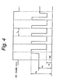
- the recording waveform shown in Fig. 4 is used.
- first prepared is the disc substrate 2 having a thickness around 1.2 mm and made of a material permitting at least laser light to pass through, such as polycarbonate resin, polyolefin resin, acrylic resin or glass. Thereafter, tracking groove 11 is made in a spiral form.
- ZnS-SiO 2 is stacked by sputtering, for example, to form the first dielectric film 3 of ZnS-SiO 2 .
- a GeInSbTe alloy is stacked as a phase change versatile material on the first dielectric film 3 by sputtering, for example, to form the phase change versatile recording film 4.
- a Ge p In q Sb r Te s material is used as a target to satisfy the relations of 1 ⁇ p ⁇ 6, 2 ⁇ q ⁇ 6 and 2.2 ⁇ r/s ⁇ 3.0.
- simultaneous sputtering may be done by using a target of Ge, target of In, target of Sb and target of Te, or vacuum evaporation is also usable.
- phase-changing speed of the phase change versatile recording film 4 can be increased, and the recording characteristics of the optical disc 1 at high linear velocities can be enhanced.
- ZnS-SiO 2 is stacked on the second dielectric film 4 by sputtering, for example, to form the second dielectric film 5.
- the protective film 7 for protecting films of the disc substrate 2 is formed on the reflective film 6.
- Results of the first experiment are shown in Table 1 below. Ranges of numerical values indicated under the items, NWS, PP and RC, are their standard ranges. In the items of PP and RC, standard values before and after recording are shown together. When each evaluation result about NWS, PP and RC is in the standard range, " ⁇ " is indicated, and if it is out of the standard range, "X" is indicated.
- the first dielectric film, phase change versatile recording film, second dielectric film and reflective film were formed on each disc substrate, variously changing these films in thickness to obtain optical discs. After that, recording characteristics of these various optical discs were evaluated.
- evaluation was made at two kinds of linear velocities for recording, namely, 4.8 m/s (four-times velocity) and 12 m/s (ten-times velocity).
- the measurement/evaluation apparatus and recording densities of optical discs used in the second experiment were the same as those of the first experiment, and the recording strategy and the recording power were optimized.
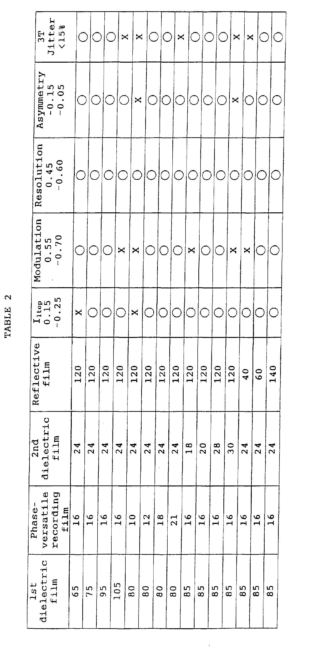
- I top in the range of 15 through 25%, modulation in the range of 55 to 70%, resolution in the range of 45 to 60%, asymmetry in the range of -15 to 5%, and 3T jitters not higher than 15% are within the standard ranges.
- modulation, resolution, asymmetry and 3T jitters falls within the standard range, " ⁇ " is indicated, and if it is out of the standard range, "X" is indicated.
- thickness of the first dielectric film is changed variously in the range from 65 to 105 nm while optimizing thickness of the other films, when the thickness is 65 nm below 75 nm, I top comes out of the standard range, and when the thickness is 105 nm beyond 95 nm, all items other than I 14h come out of the standard ranges .
- thickness of the first dielectric film is 75 nm, 80 nm, 85 nm and 90 nm (75 to 90 nm), all characteristics come within the standard ranges. Therefore, thickness of the first dielectric film should be chosen from the range larger than 65 nm and less than 105 nm, and more preferably from the range of 75 to 95 nm.
- the first dielectric film and the phase change versatile recording film are optimized in thickness to 85 nm and 16 nm, respectively, and thickness of the second dielectric film is changed variously in the range of 18 to 30 nm
- thickness of the second dielectric film is 18 nm below 20 nm
- modulation comes out of the standard range.
- thickness of he second dielectric film is 30 nm
- modulation, asymmetry and 3T jitter come out of the standard ranges.
- thickness of the second dielectric film is changed to 20 nm, 24 nm and 28 nm, all items come within the standard ranges. Therefore, thickness of he second dielectric film should be selected from the range larger than 18 nm and smaller than 30 nm, and more preferably from the range of 20 to 28 nm.
- the first dielectric film, phase change versatile film, second dielectric film and reflective are formed on each disc substrate, changing compositions of the phase change versatile recording films variously, to make up optical discs.
- two kinds of linear velocities for recording namely, 4.8 m/s (four-times velocity) and 12 m/s (ten-times velocity)
- jitter characteristics were evaluated with these various optical discs.
- optical discs after recording were held for 100 hours in an atmosphere held at the temperature of 80°C and humidity of 85%, and evaluation was carried out thereafter to confirm whether reproduction characteristics of these optical discs deteriorated, that is, whether they were acceptable in storage stability.
- the measurement/evaluation apparatus and recording densities of optical discs used in the third experiment were the same as those of the first experiment, and the recording strategy and the recording power were optimized.
- Results of the third experiment are shown in Table 3 below.
- the range of numerical values under the item of jitter indicates the standard range. That is, jitters of 15% or less are within the standard range.
- ⁇ is indicated, and if it is out of the standard range, i.e. in excess of 15%, "X” is indicated.
- Storage stability when it deteriorates, "X” is indicated, and when no deterioration or changes occurs, " ⁇ " is indicated.
- the first dielectric film, phase change versatile recording film and second dielectric film were formed on each disc substrate.
- reflective films with various composition ratios were stacked on the second dielectric films, thereby to obtain optical discs.
- jitter characteristics were evaluated with these various optical discs under the recording linear velocity of 4.8 m/s (four-times velocity) .
- these optical discs were stored for 100 hours in an atmosphere at the temperature of 80°C and the humidity of 85%, and evaluation was carried out to confirm whether any corrosion occurred on surfaces of the reflective films, i.e., whether resistance to corrosion is good or not.
- the measurement/evaluation apparatus and recording densities of optical discs used in the fourth experiment were the same as those of the first experiment, and the recording strategy and the recording power were optimized.
- results of the fourth experiment are shown in Table 4 below.
- the range of numerical values under the item of jitter indicates the standard range. That is, jitters of 15% or less are within the standard range.
- ⁇ is indicated, and if it is out of the standard range, i.e. in excess of 15%, "X” is indicated.
- resistance to corrosion when there is corrosion, "X” is indicated, and when there is no corrosion, " ⁇ ” is indicated.
- the reflective film should be made of an AgPdCu alloy, preferably having the composition ratio of Pd in the range of 0.5 to 1.5 weight %, and preferably in the range of 0.9 to 1.5 weight %, and having the composition ratio of Cu in the range of 0.9 to 1.1 weight % near 1 weight %.
- the 85 nm thick first dielectric film 3, 16 nm thick phase change versatile recording film 4, 24 nm thick second dielectric film 5 and 80 nm thick reflective film 6 were formed on each disc substrate 2 to make up optical discs 1. Then, information signals were recorded on the optical discs 1 at the linear velocity of 4.8 m/s (four-times velocity). Additionally, information signals were recorded on similar optical discs 1 at the linear velocity of 12 m/s (ten-times velocity). Furthermore, under these two linear velocities, overwrite was repeated, and jitter characteristics and were evaluated.
- the measurement/evaluation apparatus and recording densities of optical discs used in the fifth experiment were the same as those of the first experiment, and the recording strategy and the recording power were optimized.
- Figs. 5A and 5B show results of the fifth experiment.
- Fig. 5A shows dependency of 3T jitter upon overwrite frequency at the linear velocity of 4.8 m/s
- Fig. 5B shows dependency of 3T jitter upon overwrite frequency at the linear velocity of 12 m/s.
- 3T jitters of both marks and spaces are shown.
- optical discs according to the first embodiment were confirmed to be able to record and reproduce information while maintaining sufficient recording characteristics at both linear velocities in the range from 4.8 m/s to 12 m/s.
- the phase change versatile recording film 4 in the optical disc 1 is made of a GeInSbTe alloy material; the reflection film is made of an AgPdCu alloy material; the GeInSbTe alloy material forming the phase change versatile recording film 4 contains Ge in the range from 1 to 6 weight %, In in the range from 2 to 6 weight %, and Sb/Te ratio in the range from 2.4 to 3.0; the AgPdCu alloy material forming the reflective film 6 contains Pd in the range from 0.9 to 1.5 weight % and Cu in the range from 0.9 to 1.1 weight %; groove depth is in the range from 40 to 50 nm; groove width is in the range from 0.40 to 0.65 ⁇ m; thickness of the first dielectric film 3 is in the range from 75 to 95 nm; thickness of the phase change versatile recording film 4 is in the range from 12 to 18 nm; thickness of the second dielectric film 5 is in the range from 20 to 28 nm, and thickness of the reflection film 6 is in the range from the range from
- phase change versatile optical discs wavelength of laser light: 780 nm; capacity: 650 MB; track pitch: 1.6 ⁇ m, (during reproduction, NA: 0.45; reflectance: 15 to 25%: modulation: 55 to 70%; resolution: 45 to 60%); (during recording, NA: 0.5; repetitive recording frequency: 1000 times or more)) even when the linear velocity is 12 m/s not lower than 4.8 m/s. Therefore, sufficient recording power margin can be made.
- the reflective film 6 is made of an AlCu alloy. Content of Cu in the AlCu alloy is controlled in the range not higher than 1.5 weight %, and more specifically, to 1 weight %, for example.
- the other configuration of the optical disc according to the second embodiment is the same as the first embodiment, and its explanation is omitted here.
- the first dielectric film, phase change versatile recording film and second dielectric film were first formed on each disc substrate. Thereafter, reflective films made of AlCu alloys different in composition were stacked on the second dielectric films to make up optical discs. After that, with these various optical discs, jitter characteristics were evaluated at the recording linear velocity of 4.8 m/s (four-times velocity). Further, these optical discs were stored for 100 hours in an atmosphere controlled at the temperature of 80°C and the humidity of 85%, evaluation was made to confirm whether erosion occurred on surfaces of the reflective films, that is, whether the optical discs were good in resistance to corrosion. The measurement/evaluation apparatus and recording densities of optical discs used in the sixth experiment were the same as those of the first experiment, and the recording strategy and the recording power were optimized.
- results of the sixth experiment are shown in Table 5 below.
- the range of numerical values under the item of jitter indicates the standard range. That is, jitters of 15% or less are within the standard range.
- ⁇ is indicated, and if it is out of the standard range, i.e. in excess of 15%, "X” is indicated.
- resistance to corrosion when there is corrosion, "X” is indicated, and when there is no corrosion, " ⁇ ” is indicated.
- the reflective film 6 according to the second embodiment has to be made of an AlCu alloy containing at least Cu in the range not higher than 2 weight %, and more preferably in the range not higher than 1.5 weight %.
- the second embodiment which is the same as the first embodiment except the reflective film 6 made of an AlCu alloy, ensures the same effects as those of the first embodiment.
- film deposition methods and materials of disc substrates and protective films proposed in the foregoing embodiments are not but mere examples, and different film deposition methods or disc substrates or protective films made of other materials may be used, if necessary.
- any other material may be used provided the extinction coefficient k is not larger than 0.3.
- usable as materials of the first dielectric film and the second dielectric film are materials made of, or containing as a major component, nitrides, oxides, carbides, fluorides, sulfides, nitric oxides, nitric carbides or oxycarbides of metals or semi-metals like Al, Si, Ta, Ti, Zr, Nb, Mg, B, Zn, Pb, Ca, La, Ge, and so on.
- the first dielectric film 3 and the second dielectric film 5 are AlN x (0.5 ⁇ x ⁇ 1, especially AlN), Al 2 O 3-x (0 ⁇ x ⁇ 1 (especially Al 2 O 3 )), Si 3 N 4-x (0 ⁇ x ⁇ 1 (especially Si 3 N 4 )), SiO x (1 ⁇ x ⁇ 2 (especially SiO 2 , SiO), MgO, Y 2 O 3 , MgAl 2 O 4 , TiO x (1 ⁇ x ⁇ 2, especially TiO 2 )), BaTiO 3 , SrTiO 3 , Ta 2 O 5-x (0 ⁇ x ⁇ 1 (especially Ta 2 O 5 )), GeO x (1 ⁇ x ⁇ 2), SiC, ZnS, PbS, Ge-N, Ge-N-O, Si-N-O, CaF 2 , LaF, MgF 2 , NaF, TiF 4 , and so on, or materials containing them as their major components, or mixtures of these materials, such as AlN-SiO 2 , for
- the phase change versatile recording film is made of a GeInSbTe alloy material;
- the reflection film is made of an AgPdCu alloy material;
- the GeInSbTe alloy material forming the phase change versatile recording film contains Ge in the range from 1 weight % to 6 weight %, In in the range from 2 weight % to 6 weight %, and Sb in the range from 2.2 to 3.0 times of Te;
- the AgPdCu alloy material forming the reflective film contains Pd in the range from 0.9 weight % to 1.5 weight % and Cu in the range from 0.9 weight % to 1.1 weight %;
- groove depth in the groove track corrugation is in the range from 40 nm to 50 nm; distance between two boundaries, among boundaries between lands and grooves of the groove tracks, is in the range from 0.40 ⁇ m to 0.65 ⁇ m;
- thickness of the first dielectric film is in the range from 75 nm to 95 nm;
- thickness of the phase change versatile recording film is in the range from 12 n
- the phase change versatile recording film is made of a GeInSbTe alloy material; the reflection film is made of an AlCu alloy material; the GeInSbTe alloy material forming the phase change versatile recording film contains Ge in the range from 1 weight % to 6 weight %, In in the range from 2 weight % to 6 weight %, and Sb in the range from 2.2 to 3.0 times of Te; the AlCu alloy material forming the reflection film contains Cu not exceeding 1.5 weight %; groove depth in the groove track corrugation is in the range from 40 nm to 50 nm; distance between two boundaries, among boundaries between lands and grooves of the groove tracks, is in the range from 0.40 ⁇ m to 0.65 ⁇ m; thickness of the first dielectric film is in the range from 75 nm to 95 nm; thickness of the phase change versatile recording film is in the range from 12 to 18 nm; thickness of the second dielectric film is in the range from 20 nm to 28 nm, and thickness of the reflection film is in
Landscapes
- Chemical & Material Sciences (AREA)
- Inorganic Chemistry (AREA)
- Optical Record Carriers And Manufacture Thereof (AREA)
- Thermal Transfer Or Thermal Recording In General (AREA)
- Optical Head (AREA)
Abstract
Description
| Groove depth (nm) | Groove width (µm) | Wobbling amplitude (nm) | NWS 0.035-0.06 | PP 0.08-0.12 | CTS before >0.05 after 0.3-0.6 |
| 45 | 0.35 | 35 | ○ | X | X |
| 45 | 0.40 | 35 | ○ | ○ | ○ |
| 45 | 0.52 | 35 | ○ | ○ | ○ |
| 45 | 0.65 | 35 | ○ | ○ | ○ |
| 35 | 0.55 | 35 | ○ | X | ○ |
| 40 | 0.55 | 35 | ○ | ○ | ○ |
| 45 | 0.55 | 35 | ○ | ○ | ○ |
| 50 | 0.55 | 30 | ○ | ○ | ○ |
| 55 | 0.55 | 30 | ○ | ○ | X |
| 45 | 0.55 | 25 | X | ○ | ○ |
| 45 | 0.55 | 30 | ○ | ○ | ○ |
| 45 | 0.55 | 40 | ○ | ○ | ○ |
| Ge weight % | In weight % | Sb/Te - | Jitter 4x <15% | Jitter 10x <15 | Storage stability | |
| 0 | 3 | 2.4 | ○ | ○ | | |
| 1 | 3 | 2.4 | ○ | ○ | ○ | |
| 6 | 3 | 2.6 | ○ | ○ | ○ | |
| 7 | 3 | 2.6 | X | X | - | |
| 2 | 0 | 2.4 | X | X | - | |
| 2 | 2 | 2.4 | ○ | ○ | ○ | |
| 4 | 6 | 2.6 | ○ | ○ | ○ | |
| 4 | 8 | 2.6 | X | ○ | - | |
| 2 | 4 | 2 | ○ | X | - | |
| 2 | 4 | 2.2 | ○ | ○ | ○ | |
| 4 | 4 | 2.8 | ○ | ○ | ○ | |
| 4 | 4 | 3.0 | ○ | ○ | ○ | |
| 4 | 4 | 3.2 | X | ○ | - |
| Al weight % | Ag weight % | Pd weight % | Cu weight % | Anti-corrosion | Jitter (4X) <15% |
| - | 100 | - | - | X | ○ |
| - | balance | 0.5 | 1 | ○ | ○ |
| - | balance | 0.9 | 1 | ○ | ○ |
| - | balance | 1.5 | 1 | ○ | ○ |
| Al weight % | Ag weight% | Pd weight % 96 | Cu weight % | Anti-corrosion | Jitter (4x) <15% |
| Balance | - | - | 1 | ○ | ○ |
| Balance | - | - | 1.5 | ○ | ○ |
| Balance | - | - | 2 | ○ | X |
Claims (12)
- An optical recording medium comprising:a substrate having ridge-and-furrow groove tracks on one major surface thereof; anda first dielectric film, phase change versatile recording film, second dielectric film and reflection film that are sequentially stacked on the one major surface of said substrate,said phase change versatile recording film being made of a GeInSbTe alloy material, and said reflection film being made of an AgPdCu alloy material,in said GeInSbTe alloy material forming said phase change versatile recording film, content of Ge being in the range from 1 weight % to 6 weight %, content of In being in the range from 2 weight % to 6 weight %, and ratio of Sb relative to Te being in the range of 2.2 times to 3.0 times, and in said AgPdCu alloy material forming said reflection film, content of Pd being in the range of 0.9 weight % to 1.5 weight %, and content of Cu being in the range of 0.9 weight % to 1.1 weight %,depth of the furrow on said groove tracks being in the range from 40 nm to 50 nm, and distance between two adjacent boundaries at opposite sides of said furrow being in the range of 0.40 µm to 0.65 µm,thickness of said first dielectric film being in the range of 75 nm to 95 nm, thickness of said phase change versatile recording film being in the range of 12 nm to 18 nm, thickness of said second dielectric film being in the range of 20 nm to 28 nm, and thickness of said reflection film being in the range of 60 nm to 140 nm.
- The optical recording medium according to claim 1 wherein wavelength of light irradiated onto said phase change versatile recording film on said optical recording medium upon execution of recording and/or erasure of information signal on or from said optical recording medium is in the range from 775 nm to 795 nm.
- The optical recording medium according to claim 1 wherein numerical aperture of a lens of an optical system used upon recording and/or erasing information signals on or from the optical recording medium is in the range from 0.49 to 0.51, and numerical aperture of a lens of an optical system used for reproducing information signals is in the range from 0.44 to 0.46.
- The optical recording medium according to claim 1 wherein recording linear density of said optical recording medium is approximately 0.59 µm per bit.
- The optical recording medium according to claim 1 wherein, in said GeInSbTe alloy material forming said phase change versatile recording film, ratio of Sb relative to Te is in the range from 2.2 times to 2.8 times.
- The optical recording medium according to claim 1 wherein said distance between two adjacent boundaries at opposite sides of said furrow is in the range from 0.52 µm to 0.65 µm.
- An optical recording medium comprising:a substrate having ridge-and-furrow groove tracks on one major surface thereof; anda first dielectric film, phase change versatile recording film, second dielectric film and reflection film that are sequentially stacked on said one major surface of said substrate,said phase change versatile recording film being made of a GeInSbTe alloy material, and said reflection film being made of an AlCu alloy material,in said GeInSbTe alloy material forming said phase change versatile recording film, content of Ge being in the range from 1 weight % to 6 weight %, content of In being in the range from 2 weight % to 6 weight %, and ratio of Sb relative to Te being in the range of 2.2 times to 3.0 times, and in said AlCu alloy material forming said reflection film, content of Cu being not more than 1.5 weight %,depth of the furrow on said groove tracks being in the range from 40 nm to 50 nm, and distance between two adjacent boundaries at opposite sides of said furrow being in the range of 0.40 µm to 0.65 µm,thickness of said first dielectric film being in the range of 75 nm to 95 nm, thickness of said phase change versatile recording film being in the range of 12 nm to 18 nm, thickness of said second dielectric film being in the range of 20 nm to 28 nm, and thickness of said reflection film being in the range of 60 nm to 140 nm.
- The optical recording medium according to claim 7 wherein wavelength of light irradiated onto said phase change versatile recording film on said optical recording medium upon execution of recording and/or erasure of information signal on or from said optical recording medium is in the range from 775 nm to 795 nm.
- The optical recording medium according to claim 7 wherein numerical aperture of a lens of an optical system used upon recording and/or erasing information signals on or from the optical recording medium is in the range from 0.49 to 0.51, and numerical aperture of a lens of an optical system used for reproducing information signals is in the range from 0.44 to 0.46.
- The optical recording medium according to claim 7 wherein recording linear density of said optical recording medium is approximately 0.59 µm per bit.
- The optical recording medium according to claim 7 wherein, in said GeInSbTe alloy material forming said phase change versatile recording film, ratio of Sb relative to Te is in the range from 2.2 times to 2.8 times.
- The optical recording medium according to claim 7 wherein said distance between two adjacent boundaries at opposite sides of said furrow is in the range from 0.52 µm to 0.65 µm.
Applications Claiming Priority (4)
| Application Number | Priority Date | Filing Date | Title |
|---|---|---|---|
| JP2000097568 | 2000-03-31 | ||
| JP2000097568 | 2000-03-31 | ||
| JP2000296187 | 2000-09-28 | ||
| JP2000296187A JP2001344808A (en) | 2000-03-31 | 2000-09-28 | Optical recording medium |
Publications (2)
| Publication Number | Publication Date |
|---|---|
| EP1150288A2 true EP1150288A2 (en) | 2001-10-31 |
| EP1150288A3 EP1150288A3 (en) | 2006-04-19 |
Family
ID=26589118
Family Applications (1)
| Application Number | Title | Priority Date | Filing Date |
|---|---|---|---|
| EP01106919A Withdrawn EP1150288A3 (en) | 2000-03-31 | 2001-03-20 | Optical recording medium |
Country Status (3)
| Country | Link |
|---|---|
| US (1) | US6551680B2 (en) |
| EP (1) | EP1150288A3 (en) |
| JP (1) | JP2001344808A (en) |
Cited By (1)
| Publication number | Priority date | Publication date | Assignee | Title |
|---|---|---|---|---|
| EP1385160A3 (en) * | 2002-07-22 | 2004-05-19 | Ricoh Company | Phase change optical recording medium |
Families Citing this family (2)
| Publication number | Priority date | Publication date | Assignee | Title |
|---|---|---|---|---|
| TWI351696B (en) * | 2003-07-24 | 2011-11-01 | Panasonic Corp | Information recording medium and method for produc |
| US9219729B2 (en) | 2004-05-19 | 2015-12-22 | Philip Drope | Multimedia network system with content importation, content exportation, and integrated content management |
Family Cites Families (9)
| Publication number | Priority date | Publication date | Assignee | Title |
|---|---|---|---|---|
| TW372314B (en) * | 1996-11-25 | 1999-10-21 | Hitachi Maxell | Data recording medium and data regeneration apparatus thereof |
| JP3255051B2 (en) * | 1996-12-05 | 2002-02-12 | 三菱化学株式会社 | Optical information recording medium |
| EP1146509B1 (en) * | 1997-03-27 | 2005-03-16 | Mitsubishi Chemical Corporation | Optical information recording medium |
| EP1628296B1 (en) * | 1997-11-17 | 2013-03-06 | Mitsubishi Kagaku Media Co., Ltd. | Optical information recording medium |
| JPH11154354A (en) * | 1997-11-20 | 1999-06-08 | Ricoh Co Ltd | Optical recording medium |
| JPH11250502A (en) * | 1998-02-26 | 1999-09-17 | Sony Corp | optical disk |
| US6007889A (en) * | 1998-06-22 | 1999-12-28 | Target Technology, Llc | Metal alloys for the reflective or the semi-reflective layer of an optical storage medium |
| JP4260972B2 (en) * | 1999-03-30 | 2009-04-30 | ソニー株式会社 | Optical recording medium |
| US20010015949A1 (en) * | 1999-12-28 | 2001-08-23 | Toshihiko Nagase | Optical recording medium and recording-reproducing apparatus |
-
2000
- 2000-09-28 JP JP2000296187A patent/JP2001344808A/en active Pending
-
2001
- 2001-03-20 EP EP01106919A patent/EP1150288A3/en not_active Withdrawn
- 2001-03-30 US US09/822,556 patent/US6551680B2/en not_active Expired - Fee Related
Cited By (2)
| Publication number | Priority date | Publication date | Assignee | Title |
|---|---|---|---|---|
| EP1385160A3 (en) * | 2002-07-22 | 2004-05-19 | Ricoh Company | Phase change optical recording medium |
| US6958180B2 (en) | 2002-07-22 | 2005-10-25 | Ricoh Company, Ltd. | Phase change optical recording medium |
Also Published As
| Publication number | Publication date |
|---|---|
| US6551680B2 (en) | 2003-04-22 |
| JP2001344808A (en) | 2001-12-14 |
| EP1150288A3 (en) | 2006-04-19 |
| US20010036527A1 (en) | 2001-11-01 |
Similar Documents
| Publication | Publication Date | Title |
|---|---|---|
| KR100479703B1 (en) | Information recording medium, manufacturing method of the medium and recording method of the medium | |
| KR100598755B1 (en) | Optical recording media | |
| US5688574A (en) | Optical recording medium | |
| US20010016242A1 (en) | Information recording medium | |
| KR100586875B1 (en) | Rewritable Optical Information Media | |
| KR20020026187A (en) | Optical recording medium and use of such optical recording medium | |
| EP1406254B1 (en) | Optical recording medium | |
| US5876822A (en) | Reversible optical information medium | |
| EP1310953B1 (en) | Phase-change recording element for write-once applications | |
| US6551681B2 (en) | Optical recording medium | |
| EP1486964B1 (en) | Method for manufacturing an optical information recording medium | |
| EP1283522B1 (en) | Phase-change recording element for write once applications | |
| EP1143430B1 (en) | Optical recording medium | |
| US5935672A (en) | Reversible optical information medium | |
| JP2002518782A (en) | Rewritable optical information medium | |
| KR20010080202A (en) | Rewritable optical information recording medium | |
| KR19990044139A (en) | Reversible Optical Information Medium | |
| US6551680B2 (en) | Optical recording medium | |
| EP1724772A2 (en) | Phase-change type optical information recording medium | |
| KR20030017535A (en) | Rewritable optical data storage medium and use of such a medium | |
| US20030232278A1 (en) | Optical recording medium | |
| KR20050026477A (en) | Multi-stack optical data storage medium and use of such medium | |
| JPH08249721A (en) | Optical recording medium | |
| JP2001331970A (en) | Optical information recording medium | |
| JPH09265657A (en) | Optical recording medium |
Legal Events
| Date | Code | Title | Description |
|---|---|---|---|
| PUAI | Public reference made under article 153(3) epc to a published international application that has entered the european phase |
Free format text: ORIGINAL CODE: 0009012 |
|
| AK | Designated contracting states |
Kind code of ref document: A2 Designated state(s): AT BE CH CY DE DK ES FI FR GB GR IE IT LI LU MC NL PT SE TR |
|
| AX | Request for extension of the european patent |
Free format text: AL;LT;LV;MK;RO;SI |
|
| PUAL | Search report despatched |
Free format text: ORIGINAL CODE: 0009013 |
|
| AK | Designated contracting states |
Kind code of ref document: A3 Designated state(s): AT BE CH CY DE DK ES FI FR GB GR IE IT LI LU MC NL PT SE TR |
|
| AX | Request for extension of the european patent |
Extension state: AL LT LV MK RO SI |
|
| RIC1 | Information provided on ipc code assigned before grant |
Ipc: G11B 7/30 20060101ALI20060227BHEP Ipc: G11B 7/007 20060101ALI20060227BHEP Ipc: G11B 7/24 20060101AFI20010905BHEP |
|
| AKX | Designation fees paid | ||
| STAA | Information on the status of an ep patent application or granted ep patent |
Free format text: STATUS: THE APPLICATION IS DEEMED TO BE WITHDRAWN |
|
| 18D | Application deemed to be withdrawn |
Effective date: 20061020 |
|
| REG | Reference to a national code |
Ref country code: DE Ref legal event code: 8566 |