EP1150248A2 - Digital image processing method for edge contrast enhancement using wavelet transform - Google Patents

Digital image processing method for edge contrast enhancement using wavelet transform Download PDF

Info

Publication number
EP1150248A2
EP1150248A2 EP01201374A EP01201374A EP1150248A2 EP 1150248 A2 EP1150248 A2 EP 1150248A2 EP 01201374 A EP01201374 A EP 01201374A EP 01201374 A EP01201374 A EP 01201374A EP 1150248 A2 EP1150248 A2 EP 1150248A2
Authority
EP
European Patent Office
Prior art keywords
image
gradient
edge
wavelet
resolution
Prior art date
Legal status (The legal status is an assumption and is not a legal conclusion. Google has not performed a legal analysis and makes no representation as to the accuracy of the status listed.)
Withdrawn
Application number
EP01201374A
Other languages
German (de)
French (fr)
Other versions
EP1150248A3 (en
Inventor
Gina N. Larossa
Hsien-Chie Lee
Current Assignee (The listed assignees may be inaccurate. Google has not performed a legal analysis and makes no representation or warranty as to the accuracy of the list.)
Eastman Kodak Co
Original Assignee
Eastman Kodak Co
Priority date (The priority date is an assumption and is not a legal conclusion. Google has not performed a legal analysis and makes no representation as to the accuracy of the date listed.)
Filing date
Publication date
Application filed by Eastman Kodak Co filed Critical Eastman Kodak Co
Publication of EP1150248A2 publication Critical patent/EP1150248A2/en
Publication of EP1150248A3 publication Critical patent/EP1150248A3/en
Withdrawn legal-status Critical Current

Links

Images

Classifications

    • GPHYSICS
    • G06COMPUTING OR CALCULATING; COUNTING
    • G06TIMAGE DATA PROCESSING OR GENERATION, IN GENERAL
    • G06T5/00Image enhancement or restoration
    • G06T5/10Image enhancement or restoration using non-spatial domain filtering
    • GPHYSICS
    • G06COMPUTING OR CALCULATING; COUNTING
    • G06TIMAGE DATA PROCESSING OR GENERATION, IN GENERAL
    • G06T5/00Image enhancement or restoration
    • G06T5/73Deblurring; Sharpening
    • GPHYSICS
    • G06COMPUTING OR CALCULATING; COUNTING
    • G06TIMAGE DATA PROCESSING OR GENERATION, IN GENERAL
    • G06T2207/00Indexing scheme for image analysis or image enhancement
    • G06T2207/20Special algorithmic details
    • G06T2207/20048Transform domain processing
    • G06T2207/20064Wavelet transform [DWT]
    • GPHYSICS
    • G06COMPUTING OR CALCULATING; COUNTING
    • G06TIMAGE DATA PROCESSING OR GENERATION, IN GENERAL
    • G06T2207/00Indexing scheme for image analysis or image enhancement
    • G06T2207/20Special algorithmic details
    • G06T2207/20172Image enhancement details
    • G06T2207/20192Edge enhancement; Edge preservation

Definitions

  • This invention relates to digital image processing methods for improving the apparent sharpness of images.
  • the invention is directed to a class of such methods known as edge reconstruction.
  • the invention can be used in various applications where image signals are processed and displayed or printed, such as in digital printing, photofinishing, medical imaging, video imaging, motion pictures, and graphic arts.
  • the local histogram modification method is based on the idea that if the gray level differences among neighboring pixels are stretched out by modifying the histogram of a local window, the contrast of the image details will be more visible and the image will appear sharper.
  • the edge reconstruction method extracts edge information from an input image at many spatial scales. At each scale, the edges are manipulated to enhance their sharpness. The final output image is then reconstructed from the modified edge signals.
  • U.S. Patent No. 6,005,983 teaches an edge reconstruction method of image enhancement based on a Laplacian pyramid. At each resolution, the Laplacian of the image signal is clipped and then processed through a high-pass filter to sharpen the Laplacian response. The output image is reconstructed from the modified Laplacian pyramid.
  • One drawback with this technique is that the Laplacian is sensitive to noise. Furthermore, because clipping affects every spatial frequency, it is difficult to control the way edges are sharpened in the high-pass filtering.
  • U.S. Patent No. 5,963,676 teaches a method of image enhancement by a different implementation of the Laplacian pyramid.
  • An input image is filtered with a series of low-pass filters.
  • four one-dimensional Laplacian operators at different angles are applied to the low-passed image signal.
  • the Laplacian response (unsharp masked signal) is then amplified through a nonlinear function and then added to the input image to create sharper-appearing edges.
  • the nonlinear function has an upper clipping limit, a lower undershoot limit, and a middle linear-gain range.
  • the linear gain is set very high so that the directional Laplacian can pick up very fine vessel structures and render them with very high contrast.
  • the method is obviously designed for x-ray angiography for its emphasis on curve structures, but not for other types of edge or texture.
  • Adding the Laplacians of an image to enhance the image sharpness is basically an unsharp masking approach and suffers from the problems of creating overshoots along edges and failing to differentiate between different types of edges, such as texture, shading and occlusion boundaries in an image.
  • Mallat and Zhong teaches a method of edge-wavelet multiresolution analysis for image representation and compression in their paper, "Characterization of signals from multiscale edges,” published in IEEE Transactions on Pattern Analysis and Machine Intelligence, 14, 7, 710-732, 1992. Image compression is achieved in their work by finding and keeping only the local extrema in their edge-wavelet coefficients. Finding local extrema of image gradients as an edge detector is commonly known as Canny's edge detector proposed by F. Canny, in his paper, "A computational approach to edge detection," IEEE Transactions on Pattern Analysis and Machine Intelligence , vol. PAMI-8, 6, 679-698, November 1986. Mallat and Zhong also teaches a method of image reconstruction from edge-wavelet extrema by iterative projection onto feasible solution sets. The iterative projection method is too computationally intensive, and hence too time-consuming to be of practical use on commonly available image processing computers such as personal computers. It currently takes several hours to process a single image using the iterative projection method.
  • Vuylsteke and Schoeters also teach a method of contrast enhancement in their paper, “Multiscale image contrast amplification,” published in SPIE Proceedings, Volume 2167, 551-560, 1994. Their method uses a power function for amplifying the edge contrast.
  • U.S. Patent No. 5,717,791 teaches a method of image contrast enhancement based on the combination of Mallat and Zhong's edge-wavelet transform and Lu, Healy, and Weaver's idea of amplifying wavelet coefficients.
  • a constraint is imposed on the amplification factor such that the factor is a function of the average wavelet maxima.
  • the larger wavelet coefficients get amplified less than the smaller wavelet coefficients.
  • the motivation was to amplify the low contrast edges more than the high contrast edges.
  • the amplitude of wavelet coefficient is not an intrinsic edge property, because it depends on the image metric. For example, when a digital image is scaled up by a factor of 10, all the wavelet coefficients are also scaled up by a factor of 10. Therefore, wavelet amplitudes alone do not specify the nature of the edges.
  • This reconstruction transform is also slow when implemented on relatively low speed computers because of its iterative processes.
  • the prior edge reconstruction methods for image enhancement suffer from two common drawbacks: (1) the iterative reconstruction process is too slow, and (2) the amplification of the edge contrast does not take into account the intrinsic properties of the edge. There is a need therefore for an improved method of image processing using edge reconstruction to enhance the appearance of the image that avoids these problems of the prior art.
  • the need is met according to the present invention by providing a digital image processing method that includes the steps of: transforming the digital image using an edge sensitive wavelet transform to produce a plurality of wavelet coefficients at various resolutions and a residual image; modifying the wavelet coefficients as a function of the image gradient and its rate of change at a resolution corresponding to the respective wavelet coefficient; and inverse transforming the modified wavelet coefficients and the residual image to produce a processed digital image.
  • One advantage of this invention is to greatly increase the speed of computation in the edge reconstruction method by computing a wavelet coefficient-scaling mask for modifying wavelet coefficients at each resolution. A factor of 20 reduction in processing time has been achieved with the present invention.
  • Another advantage of this invention is to improve the sharpness of an image by modifying edge contrast according to its spatial extent as measured by the gradient curvature. Therefore, fine textures are sharpened differently than step edges. The resulting images appear naturally sharp because the sharpening process based on gradient curvature is derived from physical models of image blur.
  • the software program may be stored in a computer readable storage medium, which may comprise, for example; magnetic storage media such as a magnetic disk (such as a floppy disk) or magnetic tape; optical storage media such as an optical disc, optical tape, or machine readable bar code; solid state electronic storage devices such as random access memory (RAM), or read only memory (ROM); or any other physical device or medium employed to store a computer program.
  • a computer readable storage medium may comprise, for example; magnetic storage media such as a magnetic disk (such as a floppy disk) or magnetic tape; optical storage media such as an optical disc, optical tape, or machine readable bar code; solid state electronic storage devices such as random access memory (RAM), or read only memory (ROM); or any other physical device or medium employed to store a computer program.
  • the present invention is preferably utilized on any well-known computer system, such a personal computer. Consequently, the computer system will not be discussed in detail herein. It is also instructive to note that the images are either directly input into the computer system (for example by a digital camera) or digitized before input into the computer system (for example by scanning an original, such as a silver halide film).
  • the wavelet coefficients are the partial derivatives.
  • the partial derivatives are modified (12) as a function of the image gradient and its rate of change at a resolution corresponding to the respective wavelet coefficient by a wavelet coefficient-scaling mask to produce new partial derivatives, H ' / i and V ' / i .
  • the modified wavelet coefficients H ' / i and V ' / i and the residual image are inverse transformed (14) to produce a processed digital image.
  • the best number of resolution levels, N depends on the requirement of each application. A typical value of N is about 3 or 4.
  • a preferred edge wavelet transformation is described by Mallet and Zhong in the reference cited above.
  • a binary edge map at each spatial resolution, i is generated from the directional local maxima of image gradient at that resolution.
  • an image gradient histogram is used to generate an attenuation factor table, which contains the attenuation factor, f a , as a function of image gradient G i .
  • the rate of change in image gradient is referred to herein as the image gradient curvature.
  • a boost factor table, which contains the boost factor, f b , as a function of image gradient curvature C i is generated from user specified parameters.
  • the attenuation table and the boost table are then applied to the edge map and the image gradient to produce a wavelet coefficient-scaling mask, m i ( x , y ).
  • a color image is often expressed in three or more color records (e.g. R,G,B).
  • an input color image can be transformed (16) into one luminance component and two chrominance components.
  • the present invention can be applied ( 18 ) only to the luminance component to produce an edge shaped luminance component as shown in FIG. 2(a).
  • the edge shaped luminance component and the chrominance components are then inverse transformed ( 20 ) to produce the processed image R'G'B'.
  • the edge shaping method ( 18 ) can be applied independently to each of the input color records (R,G,B), to produce a processed image (R',G',B')as shown in FIG. 2(b).
  • the forward edge-wavelet transform will be described. All the filters used in the wavelet transforms in the preferred embodiment are all x-y separable and therefore, they are written with the subscripts x or y, depending on which direction the filter is applied.
  • the input image B 0 ( x , y ) 22 is convolved 24 with smoothing filters S x S y (designated H by Mallat and Zhong in Table 1 of Appendix A) 26 to produce a once blurred version of the input image, B 1 ( x,y ) 28.
  • a suitable smoothing filter is described in the Mallat and Zhong reference.
  • the input image is also convolved with a differentiation filter D x K y (designated G by Mallat and Zhong) 32 to produce a horizontal partial derivative H 1 ( x , y ) (designated W 1 1 by Mallat and Zhong) 34 and is convolved with a differentiation filter K x D y (designated G by Mallat and Zhong) 38 to produce a vertical partial derivative V 1 ( x , y ) (designated W 1 2 by Mallat and Zhong) 40.
  • H 1 ( x , y ) and V 1 ( x , y ) are the horizontal (x) and the vertical (y) partial derivatives (wavelet coefficients) of the input image at the finest resolution 1.
  • the process then is repeated using B 1 ( x , y ) 28 in the place of the input image.
  • B 1 ( x , y ) 28 in the place of the input image.
  • the same filters are used, but the convolution is done by skipping every other pixel, thus reducing the resolution to produce a further blurred image B 2 ( x , y ) 42, horizontal and vertical wavelet coefficients H 2 ( x , y ) 44, and V 2 ( x,y ) 46 of the once blurred image.
  • the reconstruction of the image to produce an edge sharpened image starts with the lowest resolution blurred image (the residual image) B 3 ( x , y ) 48, and first partial derivatives (wavelet coefficients), H 3 ( x , y ) 50 and V 3 ( x , y ) 52. Each of them is filtered with a different reconstruction filter, P x P y (designated H by Mallat and Zhong) 54, Q x L y (designated KL by Mallat and Zhong) 56 and L x Q y (designated LK by Mallat and Zhong) 58, respectively, by convolution 24 with the respective reconstruction filter.
  • the filtered results are summed together 62 to produce an edge sharpened version of the blurred image at level 2, B' 2 ( x , y ).
  • the convolution is computed by multiplying the kernel element with every 8th pixel in the image being convolved.
  • the same process is repeated until the output image is reconstructed at the finest resolution.
  • the convolution pixel interval is decreased by a factor of 2.
  • the convolution pixel interval corresponds to the number of zeros that are inserted into the values in the convolution kernel.
  • the filters shown in FIG. 3 and FIG. 4 are chosen to have the following kernels: n -4 -3 -2 -1 0 1 2 3 4 16 * S(n) 0 0 1 4 6 4 1 0 0 2 * D(n) 0 0 0 1 -1 0 0 0 0 0 K(n) 0 0 0 0 1 0 0 0 0 16 * P(n) 0 0 1 4 6 4 1 0 0 128 * Q(n) 0 -1 -9 -37 -93 93 37 9 1 512 * L(n) 1 8 28 56 326 56 28 8 1
  • Other kernels can be used and the kernel sizes are determined by the user's desire to fine-tune the edge shapes.
  • the partial derivatives wavelet coefficients
  • a histogram is then computed 64 from the image gradient. The gradient having the highest count in the gradient histogram is designated ⁇ i and is used as an estimate of noise level at this resolution, i .
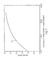
  • FIG. 6 is a plot 68 of a representative attenuation factor table, showing the absolute value of the image gradient vs. the attenuation factor.
  • a binary edge map is computed 70 by locating directional local maximum points on the image gradient. This process is well known in the prior art (see, for example, the paper by H.-C. Lee and D.R. Cok, "Detecting boundaries in a vector field," IEEE Transactions on Signal Processing , pp. 1181-1194, May 1991).
  • a pixel is labeled as an edge pixel if its image gradient is a local maximum along its gradient direction.
  • G i ( x , y ) is smaller than a threshold, ⁇ i , it is set to ⁇ i to avoid division by zero.
  • Gradient curvature, C i is an intrinsic property of an edge because it does not depend on image metric scale.
  • f b A i (1 -e - ⁇ i C i ) + b i , where A i , b i , and ⁇ i constitute the user specified set of parameters, U i .
  • FIG. 7 is a plot 74 of the values of a representative boost factor table showing the absolute value of the Laplacian of the image gradient normalized by the image gradient, vs. boost factor.
  • the value of the wavelet coefficient-scaling mask m i ( x,y ) at a non-edge pixel ( x , y ) is determined from all the neighboring edge pixels within a window W i centered at ( x , y ).
  • Each edge pixel contributes some wavelet coefficient-scaling factor to ( x , y ) and the wavelet coefficient-scaling factor m i ( x , y ) is calculated as the average of contributions from all the neighboring edge pixels in the window.
  • Let G i ( x,y ) and G i (x e ,y e ) be the image gradients at ( x , y ) and (x e ,y e ), respectively.
  • the value of h i ( x , y , x e , y e ) is constrained to be greater than or equal to 1.0. If the calculated value is less than 1.0, then it is set to 1.0. In special cases where noise suppression is desired, h i ( x , y , x e , y e ) can be constrained to have a value greater than 0.5 or some other user specified value.
  • the wavelet coefficient-scaling factor of a non-edge pixel is calculated as: where M is the total number of neighboring edge pixels in the window W ( x , y ).
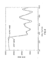
  • FIG. 8 shows a comparison between an image edge having texture detail on the right of the edge before and after edge shaping.
  • the dashed curve represents the intensity profile of a line through the input image.
  • the solid curve shows the intensity profile of the same line after the input image is processed through the edge shaping operation of the invention.
  • the major edge transition on the left half has become much steeper without obvious overshoot or undershoot.
  • the signal modulation of the texture details on the right of the edge has also been greatly enhanced.

Landscapes

  • Physics & Mathematics (AREA)
  • General Physics & Mathematics (AREA)
  • Engineering & Computer Science (AREA)
  • Theoretical Computer Science (AREA)
  • Image Processing (AREA)
  • Facsimile Image Signal Circuits (AREA)
  • Picture Signal Circuits (AREA)
  • Compression, Expansion, Code Conversion, And Decoders (AREA)

Abstract

A digital image processing method, includes the steps of: transforming the digital image using an edge sensitive wavelet transform to produce a plurality of wavelet coefficients at various resolutions and a residual image; modifying the wavelet coefficients as a function of the image gradient and its rate of change at a resolution corresponding to the respective wavelet coefficient; and inverse transforming the modified wavelet coefficients and the residual image to produce a processed digital image.

Description

This invention relates to digital image processing methods for improving the apparent sharpness of images. In particular, the invention is directed to a class of such methods known as edge reconstruction. The invention can be used in various applications where image signals are processed and displayed or printed, such as in digital printing, photofinishing, medical imaging, video imaging, motion pictures, and graphic arts.
Many factors degrade image sharpness during their capture and display processes. For example, focus error and camera shake cause image blur in the capture process, and the non-ideal system transfer functions of monitors or printers cause image blur in the display process. Prior art techniques for deblurring an image and enhancing its sharpness roughly fall into four main approaches: unsharp masking, inverse filtering, local histogram modification, and edge reconstruction. Unsharp masking works by decomposing an input image into a low frequency component and a high frequency component. The latter is then amplified and added back to the low frequency component to create a sharper-appearing output image. The inverse filtering approach is aimed at explicitly reversing the blurring process by applying a filtering operation which is an inverse of the image blurring operation. Because of its sensitivity to noise, inverse filtering is often applied with some smoothness constraint on the output image signal. The local histogram modification method is based on the idea that if the gray level differences among neighboring pixels are stretched out by modifying the histogram of a local window, the contrast of the image details will be more visible and the image will appear sharper. The edge reconstruction method extracts edge information from an input image at many spatial scales. At each scale, the edges are manipulated to enhance their sharpness. The final output image is then reconstructed from the modified edge signals.
U.S. Patent No. 6,005,983 teaches an edge reconstruction method of image enhancement based on a Laplacian pyramid. At each resolution, the Laplacian of the image signal is clipped and then processed through a high-pass filter to sharpen the Laplacian response. The output image is reconstructed from the modified Laplacian pyramid. One drawback with this technique is that the Laplacian is sensitive to noise. Furthermore, because clipping affects every spatial frequency, it is difficult to control the way edges are sharpened in the high-pass filtering.
U.S. Patent No. 5,963,676 teaches a method of image enhancement by a different implementation of the Laplacian pyramid. An input image is filtered with a series of low-pass filters. At each filter output, four one-dimensional Laplacian operators at different angles are applied to the low-passed image signal. The Laplacian response (unsharp masked signal) is then amplified through a nonlinear function and then added to the input image to create sharper-appearing edges. The nonlinear function has an upper clipping limit, a lower undershoot limit, and a middle linear-gain range. For its intended application in x-ray angiography, the linear gain is set very high so that the directional Laplacian can pick up very fine vessel structures and render them with very high contrast. The method is obviously designed for x-ray angiography for its emphasis on curve structures, but not for other types of edge or texture. Adding the Laplacians of an image to enhance the image sharpness is basically an unsharp masking approach and suffers from the problems of creating overshoots along edges and failing to differentiate between different types of edges, such as texture, shading and occlusion boundaries in an image.
Mallat and Zhong teaches a method of edge-wavelet multiresolution analysis for image representation and compression in their paper, "Characterization of signals from multiscale edges," published in IEEE Transactions on Pattern Analysis and Machine Intelligence, 14, 7, 710-732, 1992. Image compression is achieved in their work by finding and keeping only the local extrema in their edge-wavelet coefficients. Finding local extrema of image gradients as an edge detector is commonly known as Canny's edge detector proposed by F. Canny, in his paper, "A computational approach to edge detection," IEEE Transactions on Pattern Analysis and Machine Intelligence, vol. PAMI-8, 6, 679-698, November 1986. Mallat and Zhong also teaches a method of image reconstruction from edge-wavelet extrema by iterative projection onto feasible solution sets. The iterative projection method is too computationally intensive, and hence too time-consuming to be of practical use on commonly available image processing computers such as personal computers. It currently takes several hours to process a single image using the iterative projection method.
Lu, Healy, and Weaver teach a method of image enhancement by increasing the amplitude of the edge-wavelet coefficients at the local extrema in their paper, "Contrast enhancement of medical images using multiscale edge representation," published in Optical Engineering, 33, 7, 2151-2161, 1994. Their method relies on an iterative projection based on the self-reproduction kernel corresponding to the edge-wavelet. This approach requires a large amount of computation and on relatively low speed image processing hardware, such as a personal computer, it is very slow because it takes several long iterations for the algorithm to converge. Another weakness of this method is that the same gradient amplification factor is applied to all edges, independent of the edge properties. As a consequence, edges corresponding to noise and shading are enhanced as well as those corresponding to object boundaries and other discontinuities.
Vuylsteke and Schoeters also teach a method of contrast enhancement in their paper, "Multiscale image contrast amplification," published in SPIE Proceedings, Volume 2167, 551-560, 1994. Their method uses a power function for amplifying the edge contrast.
U.S. Patent No. 5,717,791 teaches a method of image contrast enhancement based on the combination of Mallat and Zhong's edge-wavelet transform and Lu, Healy, and Weaver's idea of amplifying wavelet coefficients. A constraint is imposed on the amplification factor such that the factor is a function of the average wavelet maxima. The larger wavelet coefficients get amplified less than the smaller wavelet coefficients. The motivation was to amplify the low contrast edges more than the high contrast edges. However, the amplitude of wavelet coefficient is not an intrinsic edge property, because it depends on the image metric. For example, when a digital image is scaled up by a factor of 10, all the wavelet coefficients are also scaled up by a factor of 10. Therefore, wavelet amplitudes alone do not specify the nature of the edges. This reconstruction transform is also slow when implemented on relatively low speed computers because of its iterative processes.
In summary, the prior edge reconstruction methods for image enhancement suffer from two common drawbacks: (1) the iterative reconstruction process is too slow, and (2) the amplification of the edge contrast does not take into account the intrinsic properties of the edge. There is a need therefore for an improved method of image processing using edge reconstruction to enhance the appearance of the image that avoids these problems of the prior art.
The need is met according to the present invention by providing a digital image processing method that includes the steps of: transforming the digital image using an edge sensitive wavelet transform to produce a plurality of wavelet coefficients at various resolutions and a residual image; modifying the wavelet coefficients as a function of the image gradient and its rate of change at a resolution corresponding to the respective wavelet coefficient; and inverse transforming the modified wavelet coefficients and the residual image to produce a processed digital image.
One advantage of this invention is to greatly increase the speed of computation in the edge reconstruction method by computing a wavelet coefficient-scaling mask for modifying wavelet coefficients at each resolution. A factor of 20 reduction in processing time has been achieved with the present invention. Another advantage of this invention is to improve the sharpness of an image by modifying edge contrast according to its spatial extent as measured by the gradient curvature. Therefore, fine textures are sharpened differently than step edges. The resulting images appear naturally sharp because the sharpening process based on gradient curvature is derived from physical models of image blur.
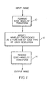
  • FIG. 1 is a block diagram showing the prior art edge wavelet transform employing a modification of the wavelet coefficients according to the present invention;
  • FIG. 2a-b show ways of applying the present invention to a luminance channel and to all color channels of an image respectively;
  • FIG. 3 is a block diagram showing the prior art forward edge-wavelet transform employed in the present invention;
  • FIG. 4 is a block diagram showing the prior art inverse edge-wavelet transform employed in the present invention;
  • FIG. 5 is a flow chart showing how the wavelet coefficient-scaling mask is generated according to the present invention;
  • FIG. 6 is a graph showing an example of the attenuation factor table used in the present invention;
  • FIG. 7 is a graph showing an example of the boost factor table used in the present invention; and
  • FIG. 8 is a comparison of the intensity profile (image code values) of a line in an image containing an edge before and after being processed according to the edge shaping method of the present invention.
  • In the following description, a preferred embodiment of the present invention will be described as a software program. Those skilled in the art will readily recognize that the equivalent of such software may also be constructed in hardware. Because image manipulation algorithms and systems are well known, the present description will be directed in particular to algorithms and systems forming part of, or cooperating more directly with, the method in accordance with the present invention. Other aspects of such algorithms and systems, and hardware and/or software for producing and otherwise processing the image signals involved therewith, not specifically shown or described herein may be selected from such systems, algorithms, components and elements known in the art. Given the method as described according to the invention in the following materials, software not specifically shown or described herein that is useful for implementation of the invention is conventional and within the ordinary skill in such arts.
    Still further, as used herein, the software program may be stored in a computer readable storage medium, which may comprise, for example; magnetic storage media such as a magnetic disk (such as a floppy disk) or magnetic tape; optical storage media such as an optical disc, optical tape, or machine readable bar code; solid state electronic storage devices such as random access memory (RAM), or read only memory (ROM); or any other physical device or medium employed to store a computer program.
    Before describing the present invention, it facilitates understanding to note that the present invention is preferably utilized on any well-known computer system, such a personal computer. Consequently, the computer system will not be discussed in detail herein. It is also instructive to note that the images are either directly input into the computer system (for example by a digital camera) or digitized before input into the computer system (for example by scanning an original, such as a silver halide film).
    The basis of the preferred embodiment of this invention is built on Canny's edge detector as used in Mallat and Zhong's edge-wavelet transform. The details of theoretical derivation and practical implementation can be found in the papers cited above. It is understood that other edge detectors or multiresolution analysis can also be used. The following description contains the preferred embodiment of the method of modifying the wavelet coefficients according to edge properties. The reconstruction of the edge-enhanced image is a one-shot process without any iteration.
    Referring to Fig. 1, the first step in the present invention is to transform (10) the digital image using an edge sensitive wavelet transform to produce a plurality of wavelet coefficients at various resolutions and a residual image, by applying a forward edge-wavelet transform to an input image, B0 (x,y) to compute its first partial derivatives, Hi (x, y) = ∂Bi -1 (x,y) /∂x and Vi (x, y) = ∂Bi -1 (x,y) / ∂y, at several spatial resolution, i = 1, 2, ..., N, and where Bi is a blurred version of Bi -1. Note that the wavelet coefficients are the partial derivatives. Next, the partial derivatives (wavelet coefficients) are modified (12) as a function of the image gradient and its rate of change at a resolution corresponding to the respective wavelet coefficient by a wavelet coefficient-scaling mask to produce new partial derivatives, H ' / i and V ' / i. Finally, the modified wavelet coefficients H ' / i and V ' / i and the residual image are inverse transformed (14) to produce a processed digital image.
    To perform the forward edge-wavelet transformation step (10), the first order partial derivatives, Hi (x,y) and Vi (x,y), of an input image at several spatial resolutions, i = 1, 2, ..., N, are computed by way of an edge-wavelet transform. The best number of resolution levels, N, depends on the requirement of each application. A typical value of N is about 3 or 4. A preferred edge wavelet transformation is described by Mallet and Zhong in the reference cited above. An image gradient amplitude Gi (x,y) is then computed from the first partial derivatives as Gi = H 2 i +V 2 i . A binary edge map at each spatial resolution, i, is generated from the directional local maxima of image gradient at that resolution. For each image resolution i, an image gradient histogram is used to generate an attenuation factor table, which contains the attenuation factor, fa , as a function of image gradient Gi . The rate of change in image gradient is referred to herein as the image gradient curvature. The image gradient curvature, Ci (x,y), at each edge pixel is computed by applying a Laplacian operator on the image gradient, and then normalizing it with the gradient value, i.e., Ci (x, y) = |▿2G i (x,y)| / Gi (x,y). A boost factor table, which contains the boost factor, fb , as a function of image gradient curvature Ci , is generated from user specified parameters.
    To perform the wavelet coefficient modification, the attenuation table and the boost table are then applied to the edge map and the image gradient to produce a wavelet coefficient-scaling mask, mi (x,y). The first partial derivatives (wavelet coefficients) Hi (x,y) and Vi (x,y), are multiplied with the wavelet coefficient-scaling mask mi (x,y) to produce the new first partial derivatives (modified wavelet coefficients), Hi ' (x, y) = mi (x,y) · Hi (x,y) and Vi ' (x, y) = mi (x, y) · Vi (x, y). The output image is then reconstructed from the new H'i and V'i , i = 1, 2, ..., N, by way of the inverse wavelet transform.
    Referring to Figs. 2 (a) and 2 (b), a color image is often expressed in three or more color records (e.g. R,G,B). In most applications, an input color image can be transformed (16) into one luminance component and two chrominance components. In order to reduce computing time, the present invention can be applied (18) only to the luminance component to produce an edge shaped luminance component as shown in FIG. 2(a). The edge shaped luminance component and the chrominance components are then inverse transformed (20) to produce the processed image R'G'B'.
    When color noise is severe or better image quality is desired, the edge shaping method (18) can be applied independently to each of the input color records (R,G,B), to produce a processed image (R',G',B')as shown in FIG. 2(b).
    Referring to Fig. 3, the forward edge-wavelet transform will be described. All the filters used in the wavelet transforms in the preferred embodiment are all x-y separable and therefore, they are written with the subscripts x or y, depending on which direction the filter is applied. First, the input image B0 (x,y) 22 is convolved 24 with smoothing filters SxSy (designated H by Mallat and Zhong in Table 1 of Appendix A) 26 to produce a once blurred version of the input image, B1 (x,y) 28. A suitable smoothing filter is described in the Mallat and Zhong reference. The input image is also convolved with a differentiation filter DxKy (designated G by Mallat and Zhong) 32 to produce a horizontal partial derivative H1 (x,y) (designated W 1 1 by Mallat and Zhong) 34 and is convolved with a differentiation filter KxDy (designated G by Mallat and Zhong) 38 to produce a vertical partial derivative V1 (x,y) (designated W 1 2 by Mallat and Zhong) 40. H1 (x,y) and V1 (x,y) are the horizontal (x) and the vertical (y) partial derivatives (wavelet coefficients) of the input image at the finest resolution 1. The process then is repeated using B1 (x,y) 28 in the place of the input image. The same filters are used, but the convolution is done by skipping every other pixel, thus reducing the resolution to produce a further blurred image B2 (x,y) 42, horizontal and vertical wavelet coefficients H2 (x,y) 44, and V2 (x,y) 46 of the once blurred image. After B2 (x,y) 42, H2 (x,y) 44, and V2 (x,y) 46 are computed, the same processes are repeated again, but the filter convolution 24 is done on every 4th pixel to produce a residual image B3 (x,y) 48, and horizontal and vertical wavelet coefficients H3(x,y) 50, and V3(x,y) 52 of the twice blurred image. Each time, a coarser resolution is computed, the convolution kernels are the same, but the pixel intervals are increased by a factor of 2. This is equivalent to the process of adding zeros into the convolution kernel as described by Mallat and Zhong. This process may be repeated three or more times depending on the desired subtlety in edge shape modification that one may desire.
    Referring to FIG. 4 the inverse edge-wavelet transform will be described. The reconstruction of the image to produce an edge sharpened image starts with the lowest resolution blurred image (the residual image) B3 (x,y) 48, and first partial derivatives (wavelet coefficients), H3 (x,y) 50 and V3 (x,y) 52. Each of them is filtered with a different reconstruction filter, PxPy (designated H by Mallat and Zhong) 54, QxLy (designated KL by Mallat and Zhong) 56 and LxQy (designated LK by Mallat and Zhong) 58, respectively, by convolution 24 with the respective reconstruction filter. The filtered results are summed together 62 to produce an edge sharpened version of the blurred image at level 2, B'2 (x,y). At level 3, the convolution is computed by multiplying the kernel element with every 8th pixel in the image being convolved.
    As is shown in FIG. 4, the same process is repeated until the output image is reconstructed at the finest resolution. For each level up, the convolution pixel interval is decreased by a factor of 2. The convolution pixel interval corresponds to the number of zeros that are inserted into the values in the convolution kernel. It should be apparent that if B3'(x,y) and all the partial derivatives (wavelet coefficients Hi' and Vi') are unmodified, i.e., B3'(x,y)=B3 (x,y), Hi'=Hi , Vi'=Vi, the reconstructed image will be the identical to the input image.
    In the preferred embodiment of the invention, the filters shown in FIG. 3 and FIG. 4 are chosen to have the following kernels:
    n -4 -3 -2 -1 0 1 2 3 4
    16 * S(n) 0 0 1 4 6 4 1 0 0
    2 * D(n) 0 0 0 1 -1 0 0 0 0
    K(n) 0 0 0 0 1 0 0 0 0
    16 * P(n) 0 0 1 4 6 4 1 0 0
    128 * Q(n) 0 -1 -9 -37 -93 93 37 9 1
    512 * L(n) 1 8 28 56 326 56 28 8 1
    Other kernels can be used and the kernel sizes are determined by the user's desire to fine-tune the edge shapes.
    Referring to FIG. 5 the way that the partial derivatives (wavelet coefficients) are modified at each resolution i will be described. First, the partial derivatives, Hi (x,y) and Vi (x,y), are used to compute 62 an image gradient Gi = H 2 i +V 2 i . A histogram is then computed 64 from the image gradient. The gradient having the highest count in the gradient histogram is designated γi and is used as an estimate of noise level at this resolution, i. Based on γ l , an attenuation factor table, ai (Gi ,γi ), is constructed 66, so that for each gradient value Gi , there is an attenuation factor, fa = ai (Gi ,γi ). In the preferred embodiment of the invention, the attenuation factor table is implemented with the following functional form: fa = G n i G n i +(α i γ i ) n . where α i and n are chosen based on the type of noise present in the image at that resolution. If noise is highly correlated from pixel to pixel, α i is decreased. For white noise, α i should set at 2.5 or higher. For most images, n is not a sensitive parameter and n = 3.0 is a good choice. FIG. 6 is a plot 68 of a representative attenuation factor table, showing the absolute value of the image gradient vs. the attenuation factor.
    A binary edge map is computed 70 by locating directional local maximum points on the image gradient. This process is well known in the prior art (see, for example, the paper by H.-C. Lee and D.R. Cok, "Detecting boundaries in a vector field," IEEE Transactions on Signal Processing, pp. 1181-1194, May 1991). A pixel is labeled as an edge pixel if its image gradient is a local maximum along its gradient direction. For each edge pixel, its gradient curvature, Ci (x,y), is computed 72 as the Laplacian of the image gradient, normalized by the gradient value, i.e., Ci (x,y) = 2 Gi (x,y)/Gi (x,y) When Gi (x,y) is smaller than a threshold, τi , it is set to τi to avoid division by zero. The threshold is not sensitive, and setting τi = 0.1γi works well for most applications. Gradient curvature, Ci , is an intrinsic property of an edge because it does not depend on image metric scale. It measures the spatial extent of an edge and therefore is a very good indicator of how sensitive an edge is to image blur. For image enhancement, an edge should be sharpened more if its gradient curvature is larger. A boost factor table, bi (Ci , Ui ), is constructed from a user specified set of edge shaping parameters, Ui , such that for each gradient curvature value, Ci , there is a boost factor fb = bi (Ci,Ui ). In the preferred embodiment of the invention, the boost factor table is implemented with the following functional form: fb = Ai (1-eiCi ) + bi , where Ai , bi , and βi constitute the user specified set of parameters, Ui . Although selection of parameters in Ui varies according to the objective of each image enhancement application, a simple criterion to set parameter values is to make an occlusion boundary in the image as sharp as an ideal step edge. FIG. 7 is a plot 74 of the values of a representative boost factor table showing the absolute value of the Laplacian of the image gradient normalized by the image gradient, vs. boost factor.
    Returning to Fig. 5, for each edge pixel (xe,ye) on the edge map, a wavelet coefficient-scaling mask mi (xe ,ye ) is computed 76 as the product of the attenuation factor and the boost factor at that pixel, i.e., mi (xe,ye ) = fa (Gi (xe,ye ),γi fb (Ci (xe ,ye ),Ui ) The value of the wavelet coefficient-scaling mask mi (x,y) at a non-edge pixel (x,y) is determined from all the neighboring edge pixels within a window Wi centered at (x,y). Each edge pixel contributes some wavelet coefficient-scaling factor to (x,y) and the wavelet coefficient-scaling factor mi (x,y) is calculated as the average of contributions from all the neighboring edge pixels in the window. Let (xe,ye ) be an edge pixel in the window Wi (x,y). Let Gi (x,y) and G i(xe,ye) be the image gradients at (x,y) and (xe,ye), respectively. The contribution from an edge pixel (xe,ye) to a non-edge pixel (x,y) is computed as follows: hi (x,y,xe ,ye ) = mi (xe ,ye )[1.0-λi Gi (xe,ye ) - Gi (x,y) Gi (x,y) ], where λi is a user specified parameter. Typical value of λ i is about 0.2. In most applications, the value of hi (x,y,xe ,ye ) is constrained to be greater than or equal to 1.0. If the calculated value is less than 1.0, then it is set to 1.0. In special cases where noise suppression is desired, hi (x,y,xe ,ye ) can be constrained to have a value greater than 0.5 or some other user specified value. The wavelet coefficient-scaling factor of a non-edge pixel is calculated as:
    Figure 00120001
    where M is the total number of neighboring edge pixels in the window W(x,y).
    Once the wavelet coefficient-scaling mask mi (x,y) is determined, the partial derivatives, Hi (x,y) and Vi (x,y), are modified 78 by the following formulas to produce the new partial derivatives, H' i (x, y) and V' i (x, y): H ' i (x, y) = mi (x,yHi (x,y) V ' i (x,y) = mi (x,yVi (x,y). The desired output image is then reconstructed from H ' / i (x, y) and V ' / i (x, y), i = 1, 2, ..., N, by the inverse edge-wavelet transform as shown in FIG. 4.
    The perceived contrast of edges and texture details in the output image is greatly enhanced by the edge shaping operation of this invention. FIG. 8 shows a comparison between an image edge having texture detail on the right of the edge before and after edge shaping. The dashed curve represents the intensity profile of a line through the input image. The solid curve shows the intensity profile of the same line after the input image is processed through the edge shaping operation of the invention. The major edge transition on the left half has become much steeper without obvious overshoot or undershoot. The signal modulation of the texture details on the right of the edge has also been greatly enhanced.
    The invention has been described with reference to a preferred embodiment. However, it will be appreciated that variations and modifications can be effected by a person of ordinary skill in the art without departing from the scope of the invention.
    Claims (10)

    1. A digital image processing method, comprising the steps of:
      a) transforming the digital image using an edge sensitive wavelet transform to produce a plurality of wavelet coefficients at various resolutions and a residual image;
      b) modifying the wavelet coefficients as a function of the image gradient and its rate of change at a resolution corresponding to the respective wavelet coefficient; and
      c) inverse transforming the modified wavelet coefficients and the residual image to produce a processed digital image.
    2. The method claimed in claim 1, wherein the edge sensitive wavelet transform is a Mallat-Zhong edge-wavelet.
    3. The method claimed in claim 1, wherein the rate of change of the gradient is determined as the normalized Laplacian of the gradient of the image at the respective resolution.
    4. The method claimed in claim 1, wherein the function of the rate of change of the gradient at resolution i, has the functional form: fb = Ai (1-eiCi ) + bii , where, Ai , bi and βi are user specified parameters, Ci = 2 Gi Gi , where Gi = H 2 i + V 2 i , and Hi = ∂B i-1 / ∂x, Vi = ∂B i-1 / ∂y, Bi is the digital image at the respective resolution, βi depends on the metric used for the digital image, such as log exposure, printing density, or linear exposure, and the wavelet coefficients are multiplied by fb .
    5. The method claimed in claim 4, wherein : 0.8 < bi < 1.5; 1.0 < Ai < 3.0;    the metric is log exposure where 2.0<βi<4.0.
    6. The method claimed in claim 1, wherein the function of the gradient at resolution i has the functional form: fa = G n i G n i +(α i γ i ) n , where αi and n are chosen based on the type of noise present in the image at resolution i, γi represents the gradient having the highest count in a gradient histogram, and Gi = H 2 i + V 2 i , and Hi = ∂B i-1 / ∂x, Vi = ∂B i-1 / ∂y, and Bi is the digital image at resolution i.
    7. The method claimed in claim 1, wherein the wavelet coefficients are modified by applying a wavelet coefficient-scaling mask mi(x,y).
    8. The method claimed in claim 7, wherein the wavelet coefficient-scaling mask is generated by:
      a) forming an edge map by locating directional local maximum points of the image gradient and labeling pixels (xe,ye) in the edge map as edge pixel if the gradient is a local maximum along the gradient direction;
      b) computing the values of the wavelet coefficient-scaling mask mi(xe,ye) at edge pixels (xe,ye) as the product of an attenuation factor fa and a boost factor fb; and
      c) computing the values of the wavelet coefficient scaling mask at non-edge pixels as the average of contributions from neighboring edge pixels.
    9. The method claimed in claim 8, wherein the attenuation factor fa is implemented with the following functional form fa = G n i G n i +(α i γ i ) n , where γi represents the gradient having the highest count in a gradient histogram, αi and n are chosen based on the type of noise present in the image at that resolution, and Gi = H 2 i + V 2 i ; and
      the boost factor fb is implemented with the following functional form fb = Ai (1-eiCi ) + bi , where Ai , bi , and β i are user specified parameters, and Ci is the gradient curvature.
    10. A computer program product for causing a computer to perform the method of claim 1.
    EP01201374A 2000-04-24 2001-04-12 Digital image processing method for edge contrast enhancement using wavelet transform Withdrawn EP1150248A3 (en)

    Applications Claiming Priority (2)

    Application Number Priority Date Filing Date Title
    US09/556,666 US6611627B1 (en) 2000-04-24 2000-04-24 Digital image processing method for edge shaping
    US556666 2000-04-24

    Publications (2)

    Publication Number Publication Date
    EP1150248A2 true EP1150248A2 (en) 2001-10-31
    EP1150248A3 EP1150248A3 (en) 2003-05-28

    Family

    ID=24222318

    Family Applications (1)

    Application Number Title Priority Date Filing Date
    EP01201374A Withdrawn EP1150248A3 (en) 2000-04-24 2001-04-12 Digital image processing method for edge contrast enhancement using wavelet transform

    Country Status (3)

    Country Link
    US (1) US6611627B1 (en)
    EP (1) EP1150248A3 (en)
    JP (1) JP2002024821A (en)

    Cited By (7)

    * Cited by examiner, † Cited by third party
    Publication number Priority date Publication date Assignee Title
    EP1349113A3 (en) * 2002-03-20 2006-01-11 Ricoh Company Image processor and image processing method
    RU2448370C1 (en) * 2011-03-22 2012-04-20 Открытое акционерное общество "Концерн радиостроения "Вега" Method of detecting electronic image modification
    US8699813B2 (en) 2010-11-19 2014-04-15 Analog Devices, Inc Adaptive filter for low-light noise reduction
    US8755625B2 (en) 2010-11-19 2014-06-17 Analog Devices, Inc. Component filtering for low-light noise reduction
    EP1890120A4 (en) * 2005-06-06 2014-07-09 Tokyo Inst Tech IMAGE CONVERSION DEVICE AND PROGRAM
    CN111079764A (en) * 2019-12-06 2020-04-28 深圳久凌软件技术有限公司 Low-illumination license plate image recognition method and device based on deep learning
    US11222412B2 (en) 2018-12-26 2022-01-11 Silicon Works Co., Ltd. Image processing device and method

    Families Citing this family (60)

    * Cited by examiner, † Cited by third party
    Publication number Priority date Publication date Assignee Title
    US7068851B1 (en) * 1999-12-10 2006-06-27 Ricoh Co., Ltd. Multiscale sharpening and smoothing with wavelets
    JP2001186353A (en) * 1999-12-27 2001-07-06 Noritsu Koki Co Ltd Image processing method and recording medium recording image processing program
    KR100343744B1 (en) * 2000-09-30 2002-07-20 엘지전자주식회사 Contrast enhancement apparatus of video signal
    US7177481B2 (en) * 2000-12-19 2007-02-13 Konica Corporation Multiresolution unsharp image processing apparatus
    US6956975B2 (en) * 2001-04-02 2005-10-18 Eastman Kodak Company Method for improving breast cancer diagnosis using mountain-view and contrast-enhancement presentation of mammography
    US7257273B2 (en) * 2001-04-09 2007-08-14 Mingjing Li Hierarchical scheme for blur detection in digital image using wavelet transform
    JP2003061105A (en) * 2001-06-07 2003-02-28 Seiko Epson Corp Image processing method, image processing program, image processing apparatus, and digital still camera using the same
    US7120308B2 (en) * 2001-11-26 2006-10-10 Seiko Epson Corporation Iterated de-noising for image recovery
    US7130483B2 (en) * 2001-12-12 2006-10-31 Samsung Electronics Co., Ltd. Method for enhancing a digital image while suppressing undershoots and overshoots
    US7176969B2 (en) * 2001-12-13 2007-02-13 International Business Machines Corporation System and method for anti-moire imaging in a one dimensional sensor array
    KR100403601B1 (en) * 2001-12-21 2003-10-30 삼성전자주식회사 Apparatus and method for enhancing edge of image
    DE10202163A1 (en) * 2002-01-22 2003-07-31 Bosch Gmbh Robert Process and device for image processing and night vision system for motor vehicles
    US7260269B2 (en) * 2002-08-28 2007-08-21 Seiko Epson Corporation Image recovery using thresholding and direct linear solvers
    US7124394B1 (en) * 2003-04-06 2006-10-17 Luminescent Technologies, Inc. Method for time-evolving rectilinear contours representing photo masks
    US7698665B2 (en) * 2003-04-06 2010-04-13 Luminescent Technologies, Inc. Systems, masks, and methods for manufacturable masks using a functional representation of polygon pattern
    US7352909B2 (en) * 2003-06-02 2008-04-01 Seiko Epson Corporation Weighted overcomplete de-noising
    US7424141B2 (en) * 2003-08-29 2008-09-09 Agilent Technologies, Inc. System and method for performing auto-focused tomosynthesis
    US7333673B2 (en) * 2003-10-30 2008-02-19 Samsung Electronics Co., Ltd. Method and apparatus for image detail enhancement without zigzagged edge artifact
    US20050105817A1 (en) * 2003-11-17 2005-05-19 Guleryuz Onur G. Inter and intra band prediction of singularity coefficients using estimates based on nonlinear approximants
    US20080025628A1 (en) * 2004-10-26 2008-01-31 Koninklijke Philips Electronics, N.V. Enhancement of Blurred Image Portions
    IL165852A (en) * 2004-12-19 2010-12-30 Rafael Advanced Defense Sys System and method for image display enhancement
    US7668387B2 (en) * 2005-06-20 2010-02-23 Intel Corporation Selective local transient improvement and peaking for video sharpness enhancement
    US7676103B2 (en) * 2005-06-20 2010-03-09 Intel Corporation Enhancing video sharpness and contrast by luminance and chrominance transient improvement
    US20070014468A1 (en) * 2005-07-12 2007-01-18 Gines David L System and method for confidence measures for mult-resolution auto-focused tomosynthesis
    WO2007033362A2 (en) * 2005-09-13 2007-03-22 Luminescent Technologies, Inc. Systems, masks, and methods for photolithography
    US7778367B1 (en) * 2005-09-23 2010-08-17 Rockwell Collins, Inc. Method and apparatus for receiving a geo-location signal
    WO2007041602A2 (en) * 2005-10-03 2007-04-12 Luminescent Technologies, Inc. Lithography verification using guard bands
    US7921385B2 (en) * 2005-10-03 2011-04-05 Luminescent Technologies Inc. Mask-pattern determination using topology types
    WO2007041701A2 (en) * 2005-10-04 2007-04-12 Luminescent Technologies, Inc. Mask-patterns including intentional breaks
    WO2007044557A2 (en) 2005-10-06 2007-04-19 Luminescent Technologies, Inc. System, masks, and methods for photomasks optimized with approximate and accurate merit functions
    EP1959390A4 (en) 2005-10-12 2010-05-05 Panasonic Corp VISUAL PROCESSING APPARATUS, DISPLAY APPARATUS, VISUAL PROCESSING METHOD, PROGRAM, AND INTEGRATED CIRCUIT
    US8139828B2 (en) * 2005-10-21 2012-03-20 Carestream Health, Inc. Method for enhanced visualization of medical images
    CN102438097B (en) * 2006-04-19 2015-06-03 松下电器(美国)知识产权公司 Visual processing device, visual processing method
    CN102238314B (en) * 2006-04-28 2013-06-12 松下电器产业株式会社 Visual processing apparatus, visual processing method, program, recording medium, display, and integrated circuit
    US7813582B1 (en) * 2006-09-25 2010-10-12 Google Inc. Method and apparatus for enhancing object boundary precision in an image
    US7844119B2 (en) * 2007-01-25 2010-11-30 Sony Corporation Wavelet detector for finding similarities between major boundaries in images
    JP4848965B2 (en) * 2007-01-26 2011-12-28 株式会社ニコン Imaging device
    US8139886B2 (en) * 2008-06-23 2012-03-20 Microsoft Corporation Blur estimation
    JP5083086B2 (en) * 2008-07-22 2012-11-28 ソニー株式会社 Image processing apparatus, image processing method, and program
    US8498499B2 (en) * 2008-07-30 2013-07-30 Mitsubishi Electric Corporation Image processing apparatus and method and image display apparatus
    US8150191B2 (en) * 2008-10-14 2012-04-03 Interra Systems Inc. Method and system for calculating blur artifacts in videos using user perception threshold
    WO2010086973A1 (en) * 2009-01-28 2010-08-05 富士通株式会社 Image processing device, image processing program, and image processing method
    EP2467055A1 (en) * 2009-08-21 2012-06-27 Auckland UniServices Limited System and method for mapping gastro-intestinal electrical activity
    US8605976B2 (en) * 2009-12-10 2013-12-10 General Electric Corporation System and method of detection of optimal angiography frames for quantitative coronary analysis using wavelet-based motion analysis
    JP2011134204A (en) * 2009-12-25 2011-07-07 Sony Corp Image processing device, image processing method and program
    US8551283B2 (en) 2010-02-02 2013-10-08 Apple Inc. Offset control for assembling an electronic device housing
    JP5804340B2 (en) * 2010-06-10 2015-11-04 株式会社島津製作所 Radiation image region extraction device, radiation image region extraction program, radiation imaging device, and radiation image region extraction method
    US8798392B2 (en) * 2010-11-10 2014-08-05 Tandent Vision Science, Inc. Method and system for generating intrinsic images using a smooth illumination constraint
    CN102081792A (en) * 2010-12-30 2011-06-01 西北农林科技大学 Multi-scale red jujube image crack edge detection method based on wavelet transformation
    US9143687B2 (en) * 2012-03-14 2015-09-22 University Of Dayton Method of analyzing motion blur using double discrete wavelet transform
    US8983187B2 (en) * 2013-03-07 2015-03-17 Cyberlink Corp. Systems and methods for performing edge enhancement in digital images
    US9123126B2 (en) * 2013-05-07 2015-09-01 Qualcomm Technologies, Inc. Method for enhancing local contrast of an image
    JP6466076B2 (en) * 2014-03-31 2019-02-06 ジーイー・メディカル・システムズ・グローバル・テクノロジー・カンパニー・エルエルシー Image processing apparatus and program
    US9852353B2 (en) * 2014-11-12 2017-12-26 Adobe Systems Incorporated Structure aware image denoising and noise variance estimation
    CN106161875B (en) * 2015-03-25 2019-02-15 瑞昱半导体股份有限公司 Image processing device and method
    US10145961B1 (en) * 2016-04-27 2018-12-04 Rockwell Collins, Inc. Efficient transform-based quantization processing
    CN107689039B (en) * 2016-08-05 2021-01-26 同方威视技术股份有限公司 Method and device for estimating image fuzziness
    CN108550158B (en) * 2018-04-16 2021-12-17 Tcl华星光电技术有限公司 Image edge processing method, electronic device and computer readable storage medium
    US11712566B2 (en) 2019-08-12 2023-08-01 Alimetry Limited Sacral nerve stimulation
    CN118196125B (en) * 2024-03-15 2025-02-11 河北工程大学 A pipe interface edge detection method based on mathematical morphology and regional connectivity

    Family Cites Families (7)

    * Cited by examiner, † Cited by third party
    Publication number Priority date Publication date Assignee Title
    DE69214229T2 (en) 1991-08-14 1997-04-30 Agfa Gevaert Nv Method and device for improving the contrast of images
    US5754697A (en) * 1994-12-02 1998-05-19 Fu; Chi-Yung Selective document image data compression technique
    US6005983A (en) 1993-09-08 1999-12-21 California Institutue Of Technology Image enhancement by non-linear extrapolation in frequency space
    DE69525127T2 (en) * 1994-10-28 2002-10-02 Oki Electric Industry Co., Ltd. Device and method for encoding and decoding images using edge synthesis and wavelet inverse transformation
    EP0712092A1 (en) * 1994-11-10 1996-05-15 Agfa-Gevaert N.V. Image contrast enhancing method
    US5963676A (en) 1997-02-07 1999-10-05 Siemens Corporate Research, Inc. Multiscale adaptive system for enhancement of an image in X-ray angiography
    US6285798B1 (en) * 1998-07-06 2001-09-04 Eastman Kodak Company Automatic tone adjustment by contrast gain-control on edges

    Cited By (11)

    * Cited by examiner, † Cited by third party
    Publication number Priority date Publication date Assignee Title
    EP1349113A3 (en) * 2002-03-20 2006-01-11 Ricoh Company Image processor and image processing method
    US7423781B2 (en) 2002-03-20 2008-09-09 Ricoh Company, Ltd. Image processor and image processing method for image enhancement using edge detection
    EP1890120A4 (en) * 2005-06-06 2014-07-09 Tokyo Inst Tech IMAGE CONVERSION DEVICE AND PROGRAM
    EP2866192A3 (en) * 2005-06-06 2015-09-23 Tokyo Institute of Technology Image transform apparatus and image transform program
    US8699813B2 (en) 2010-11-19 2014-04-15 Analog Devices, Inc Adaptive filter for low-light noise reduction
    US8755625B2 (en) 2010-11-19 2014-06-17 Analog Devices, Inc. Component filtering for low-light noise reduction
    US9563938B2 (en) 2010-11-19 2017-02-07 Analog Devices Global System and method for removing image noise
    RU2448370C1 (en) * 2011-03-22 2012-04-20 Открытое акционерное общество "Концерн радиостроения "Вега" Method of detecting electronic image modification
    US11222412B2 (en) 2018-12-26 2022-01-11 Silicon Works Co., Ltd. Image processing device and method
    CN111079764A (en) * 2019-12-06 2020-04-28 深圳久凌软件技术有限公司 Low-illumination license plate image recognition method and device based on deep learning
    CN111079764B (en) * 2019-12-06 2023-04-07 深圳久凌软件技术有限公司 Low-illumination license plate image recognition method and device based on deep learning

    Also Published As

    Publication number Publication date
    JP2002024821A (en) 2002-01-25
    US6611627B1 (en) 2003-08-26
    EP1150248A3 (en) 2003-05-28

    Similar Documents

    Publication Publication Date Title
    US6611627B1 (en) Digital image processing method for edge shaping
    US7181086B2 (en) Multiresolution method of spatially filtering a digital image
    US6373992B1 (en) Method and apparatus for image processing
    Zhang et al. Adaptive bilateral filter for sharpness enhancement and noise removal
    JP4460839B2 (en) Digital image sharpening device
    US6937772B2 (en) Multiresolution based method for removing noise from digital images
    US6937775B2 (en) Method of enhancing the tone scale of a digital image to extend the linear response range without amplifying noise
    JP3193806B2 (en) Noise reduction method and apparatus
    US8457429B2 (en) Method and system for enhancing image signals and other signals to increase perception of depth
    US6621937B1 (en) Removing chroma noise from digital images by using variable shape pixel neighborhood regions
    JP4456819B2 (en) Digital image sharpening device
    EP0971315A2 (en) Automatic tone adjustment by contrast gain-control on edges
    US20130202177A1 (en) Non-linear resolution reduction for medical imagery
    Ben Abdallah et al. Adaptive noise-reducing anisotropic diffusion filter
    US20040096103A1 (en) Method of spatially filtering a digital image using chrominance information
    JP2001005960A (en) Method and device for processing image
    US12322072B2 (en) Method and apparatus for noise reduction
    EP0574969B1 (en) A method and apparatus for noise reduction
    US7269300B2 (en) Sharpening a digital image in accordance with magnification values
    US20080137978A1 (en) Method And Apparatus For Reducing Motion Blur In An Image
    WO2021094471A1 (en) Method and apparatus for contrast enhancement
    Paranjape Fundamental enhancement techniques
    US8059905B1 (en) Method and system for thresholding
    RU2383924C2 (en) Method for adaptive increase of sharpness of digital photographs during printing
    Chow et al. Double-regularization approach for blind restoration of multichannel imagery

    Legal Events

    Date Code Title Description
    PUAI Public reference made under article 153(3) epc to a published international application that has entered the european phase

    Free format text: ORIGINAL CODE: 0009012

    AK Designated contracting states

    Kind code of ref document: A2

    Designated state(s): AT BE CH CY DE DK ES FI FR GB GR IE IT LI LU MC NL PT SE TR

    AX Request for extension of the european patent

    Free format text: AL;LT;LV;MK;RO;SI

    PUAL Search report despatched

    Free format text: ORIGINAL CODE: 0009013

    AK Designated contracting states

    Designated state(s): AT BE CH CY DE DK ES FI FR GB GR IE IT LI LU MC NL PT SE TR

    AX Request for extension of the european patent

    Extension state: AL LT LV MK RO SI

    AKX Designation fees paid
    REG Reference to a national code

    Ref country code: DE

    Ref legal event code: 8566

    STAA Information on the status of an ep patent application or granted ep patent

    Free format text: STATUS: THE APPLICATION IS DEEMED TO BE WITHDRAWN

    18D Application deemed to be withdrawn

    Effective date: 20031129