EP1150169A2 - Gas jet nozzle for extreme ultraviolet light source - Google Patents
Gas jet nozzle for extreme ultraviolet light source Download PDFInfo
- Publication number
- EP1150169A2 EP1150169A2 EP01109305A EP01109305A EP1150169A2 EP 1150169 A2 EP1150169 A2 EP 1150169A2 EP 01109305 A EP01109305 A EP 01109305A EP 01109305 A EP01109305 A EP 01109305A EP 1150169 A2 EP1150169 A2 EP 1150169A2
- Authority
- EP
- European Patent Office
- Prior art keywords
- gas
- channel
- primary
- nozzle
- housing
- Prior art date
- Legal status (The legal status is an assumption and is not a legal conclusion. Google has not performed a legal analysis and makes no representation as to the accuracy of the status listed.)
- Granted
Links
Images


Classifications
-
- G—PHYSICS
- G03—PHOTOGRAPHY; CINEMATOGRAPHY; ANALOGOUS TECHNIQUES USING WAVES OTHER THAN OPTICAL WAVES; ELECTROGRAPHY; HOLOGRAPHY
- G03F—PHOTOMECHANICAL PRODUCTION OF TEXTURED OR PATTERNED SURFACES, e.g. FOR PRINTING, FOR PROCESSING OF SEMICONDUCTOR DEVICES; MATERIALS THEREFOR; ORIGINALS THEREFOR; APPARATUS SPECIALLY ADAPTED THEREFOR
- G03F7/00—Photomechanical, e.g. photolithographic, production of textured or patterned surfaces, e.g. printing surfaces; Materials therefor, e.g. comprising photoresists; Apparatus specially adapted therefor
- G03F7/70—Microphotolithographic exposure; Apparatus therefor
- G03F7/70008—Production of exposure light, i.e. light sources
- G03F7/70033—Production of exposure light, i.e. light sources by plasma extreme ultraviolet [EUV] sources
-
- H—ELECTRICITY
- H05—ELECTRIC TECHNIQUES NOT OTHERWISE PROVIDED FOR
- H05G—X-RAY TECHNIQUE
- H05G2/00—Apparatus or processes specially adapted for producing X-rays, not involving X-ray tubes, e.g. involving generation of a plasma
- H05G2/001—Production of X-ray radiation generated from plasma
- H05G2/002—Supply of the plasma generating material
- H05G2/0023—Constructional details of the ejection system
Definitions
- the present invention is generally related to semiconductor lithography techniques and equipment, and more particularly to extreme ultraviolet (EUV) lithography.
- EUV extreme ultraviolet
- Optical projection lithography is a lithographic technique where light is refracted through camera lenses onto a masked semiconductor wafer to pattern a particular layer. This lithographic technique is currently used for the high volume manufacture of circuits having etched circuit lines of 0.18 micron dimensions or greater in width.
- the present technology for optical projection lithography cannot produce circuits with substantially smaller features due to fundamental physical limitations on the ability to focus light--smaller circuit features require a source of shorter wavelength light.
- EUV extreme ultraviolet
- UV very short wavelength ultraviolet
- a candidate technology for a practical EUV light source is a laser-produced plasma (LPP).
- LPP EUV source a target material is illuminated by a high-power laser to produce a very high temperature plasma which radiates the desired EUV light.
- the present invention pertains to a light source in which a condensable gas (vapor) is passed through a nozzle assembly in such a manner so as to produce a jet or spray containing a plurality of small droplets along with some uncondensed gas. This plurality of droplets serves collectively as the target of the laser.
- a gas jet nozzle for an extreme ultraviolet (EUV) light source comprises a housing having a primary channel adapted to couple to a primary gas source and expel a first gas/droplet stream.
- the housing also includes a secondary channel proximate the primary channel adapted to couple to a secondary gas source and adapted to expel a second gas stream. The second gas stream shapes the first gas/droplet stream expelled by the primary channel.
- EUV extreme ultraviolet
- a gas jet nozzle system for an extreme ultraviolet light (EUV) source comprising a primary gas source, a secondary gas source, and a housing.
- the housing comprises a primary channel coupled to the primary gas source and adapted to expel a first gas/droplet stream.
- the housing further comprises a secondary channel proximate the primary channel coupled to the secondary gas stream.
- the housing secondary channel is adapted to expel a second gas stream to shape the first gas/droplet stream expelled by the housing primary channel.
- a method of converting laser energy to EUV energy comprising the steps of expelling gas from a nozzle and illuminating the expelled gas with a laser to produce EUV light-emitting plasma.
- the nozzle comprises a housing having a primary channel and a secondary channel proximate the primary channel.
- the primary channel is coupled to a primary gas source
- the secondary channel is coupled to a secondary gas source.
- a first gas/droplet stream is expelled from the primary channel and a second gas stream is expelled from the secondary channel, where the second gas stream shapes the first gas/droplet stream.
- Advantages of the invention include the ability to illuminate the stream expelled from the primary channel with a laser at a distance further away from nozzles of the prior art without the loss of performance that would occur due to spreading of the expelled stream in the prior art. This is beneficial because damage to the nozzle from the generated high temperature plasma is significantly reduced, resulting in longer life of the nozzle and saving replacement costs. Furthermore, costs are reduced for replacing collection optics that become contaminated by the nozzle erosion by-products. The life of the collection optics is further increased by the fact that the secondary shroud gas flow serves to directly block some of the very fast atoms or ions emitted from the plasma that would otherwise impinge upon and erode the collection optics. Also, the nozzle of the present invention blocks a smaller fraction of the emitted EUV light from reaching the collection optics, as compared to the prior art.
- Laser-illuminated gas jets are the leading candidate as the means for production of EUV light for the next generation of semiconductor lithography equipment.
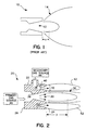
- a prior art gas jet nozzle 10 used in EUV lithography is shown in Figure 1.
- the nozzle 10 has a single channel 12 for expelling gas.
- the gas undergoes rapid lateral expansion as it leaves the nozzle exit, shown generally at 14. This is problematic in that when used with EUV lithography, a high-power laser is focused on the expelled gas to produce a high temperature plasma which emits EUV light.
- the laser must be focused close to the nozzle 10, for example. at a distance "x" away from the nozzle 10, to illuminate the necessary quantity of target gas and achieve adequate performance.
- High temperature plasma is generated close to the nozzle 10 within distance "x", which results in heating and erosion of the nozzle 10 and degradation in nozzle performance.
- the nozzle erosion by-products contaminate other optical equipment in the system.
- the nozzle 10 blocks a significant portion of the emitted EUV light and prevents the EUV light from reaching the collection optics, e.g. lenses and mirrors, not shown.
- the present invention achieves technical advantages as a nozzle having a primary channel, and a secondary channel disposed proximate the primary channel emitting gas that restricts the lateral expansion of gas from the main, primary channel.
- a first embodiment of a gas jet nozzle of the present invention is shown generally at 20 in a cross-sectional view in Figure 2, and in a perspective front view in Figure 3.
- the gas jet nozzle 20 adapted to produce extreme ultraviolet (EUV) light including a cylindrical housing 22 preferably comprising stainless steel having an annular front face 24 and an annular back face 26.
- the housing 22 has a gas-expelling primary channel 30 located axially and centrally within the housing 22, and a gas-expelling secondary channel 34 disposed proximate the primary channel 30.
- the housing 22 is adapted to couple to a primary gas source 46 preferably comprising xenon and a diluent, for example, at the back face 26.
- the housing 22 is adapted to expel a primary gas stream 36 at the front 24 via the primary channel 30 that forms EUV when illuminated with a laser.
- the secondary channel 34 of the housing 22 is adapted to coupled to a secondary gas source 44 and is adapted to expel a secondary gas stream 42.
- the secondary gas source 44 preferably comprises a non-condensing gas, for example, helium.
- the cross-sectional profile of primary channel 30 is preferably circular but may be oval, for example, and the secondary channel 34 is preferably ring-like or annular, annularly surrounding the primary channel 30.
- the secondary channel 34 is preferably located in an annular shroud 32 that is preferably comprised of a homogeneous material coupled to or molded into the nozzle housing 22. although the shroud may also be a separate component.
- the primary channel 30 has a larger diameter at the housing front (nozzle exit) 24 than a rearward point (throat) 38 near the housing back (inlet) 26 thereby forming a converging/diverging channel shape that efficiently produces droplets in the subsequent external jet.
- the secondary channel 34 has a larger diameter at the housing front 24 than a rearward point 40 disposed proximate the housing front 24 to expand the secondary gas flow provided therethrough to high velocity and form the well-collimated, high-momentum annular jet flow shown at 42.
- Figure 2 shows the secondary channel centerline as parallel to the primary channel centerline, the preferred embodiment is to have the secondary channel oriented to direct the secondary gas flow radially inward at some angle.
- the present invention derives technical advantages whereby the annular jet stream 42 expelled from the annular secondary channel 34 provides a jet "envelope” that applies a pneumatic pressure and a momentum (“dynamic pressure") that restricts the lateral expansion of primary gas stream 36 expelled from the primary channel 30, thereby optimizing gas jet properties by providing a narrow, coherent dense primary stream 36.
- the annular jet of secondary gas 42 provides the desired density of the target gas 36 at a more favorable distance "y" from the nozzle 20 exit opening.
- the gas forming the gas flow stream 42 from the secondary channel 34 is selected to be optically transparent to both the directed laser and generated EUV light.
- the increased displacement "y" of the laser focus and required gas density from the nozzle 20 is significantly greater than displacement "x" of prior art nozzles, and is beneficial in many respects.
- a second embodiment of the present invention is shown generally at 60 in the perspective view of Figure 4.
- a housing 62 may comprise several assemblies coupled together, to be described further herein.
- the primary gas source 46 (not shown) is coupleable to a primary gas inlet 84 at a housing back 66
- the secondary gas source 44 (not shown) is coupleable to a secondary or shroud gas inlet 86 preferably on the side of the housing 66.
- An optional coolant inlet 88 and coolant outlet 90 located near the housing front 64 are coupleable to a coolant supply (not shown) and route coolant about housing 62 to reduce operating temperatures thereof when generating EUV.
- a side view of the gas jet nozzle 60 is shown in Figure 5.
- a cooling jacket 92 having a tapered tip is coupled to and covers a nozzle assembly 96 and is coupled to a sleeve assembly 98.
- a shim may be coupled to the sleeve assembly 98, for example.
- the nozzle assembly 96 is shown separately in Figure 6.
- the nozzle assembly 96 comprises a hollow tube 104 that encloses a primary gas-expelling channel 70.
- the tube 104 has an external surface 105 and is terminated at a distal end to form a primary nozzle tip 100 having the preferred dimensions as described with reference to Figure 2.
- An optional positioning attachment 102 may be defined about tip 100 and comprise wire that serves to adjustably position the nozzle tip 100 within the sleeve assembly 98 and adjust the orientation of the flow of secondary gas stream 82 therethrough, as shown in Figure 8.
- the sleeve assembly 98 has an inwardly extending splined section (not shown) that keeps the tube 104 securely centered within the sleeve assembly 98 while allowing passage of the secondary gas stream therebetween.
- the tube 104 has a flange 106 securely defined near the primary gas inlet 84, as shown, which is secured to and against a nut 108 by a flanged cover 109, as shown in Figure 5.
- the sleeve assembly 98 is shown separately in Figure 7 comprising a tube 110 having an interior surface 112.
- the tube 110 has a larger diameter than tube 104 of the nozzle assembly 96.
- Tube 110 of the sleeve assembly 98 is positioned over and around the tube 104 of the nozzle assembly 96 so that an annular cavity is formed between the external surface 105 of tube 104 and the interior surface 112 of tube 110, forming a secondary channel 74.
- the sleeve assembly 98 comprises the shroud or secondary gas inlet 86.
- the sleeve assembly 98 also comprises a fitting 114 and a coupling nut 116 for receiving the secondary gas source.
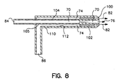
- FIG. 8 A cross-section of a portion of the assembled gas jet nozzle 60 of the present invention is shown in Figure 8, illustrating the secondary 74 channel formed between the exterior surface 105 of nozzle assembly tube 104 and the interior surface 112 of the sleeve assembly tube 110.
- Primary gas enters the primary gas inlet 84 and passes through the primary channel 70. The primary gas is expelled from the primary nozzle tip 100 as a primary stream 76.
- Secondary gas enters the secondary gas inlet 86 and passes through the secondary channel 74. The secondary gas is expelled proximate the primary stream 76 near the opening of the nozzle tip 100 and forms an enveloping secondary gas stream 82 restricting the lateral expansion of the primary gas stream 76 as previously described.
- the novel gas jet nozzle 20, 60 disclosed and described herein provides several advantages.
- the annular gas flow stream 42, 82 from the annular secondary channel 34, 74, respectively, provides pneumatic pressure about and to the gas flow stream 36, 76 from the primary channel 30, 70, respectively, restricting the lateral expansion of the main gas flow stream 36, 76, respectively.
- the gas stream 42, 82 from the secondary channel 34, 74, respectively, axially guides the primary gas stream 36, 76, respectively, to be emitted from the nozzle 20, 60 in a more perpendicular direction to the plane defined by front face 24.
- a laser is illuminated into the gas flow 36 and focused at a distance "y" away from the exit at the nozzle front 24. This is beneficial for several reasons.
- the EUV jet nozzle 20. 60 is described herein with respect to semiconductor lithography, the jet nozzle design 20, 60 is beneficial for other EUV applications, such as materials science and microscopy, for example.
- the nozzle 20, 60 housing 22, 62 preferably comprises a material suitable for a high temperature environment, and resistant to sputtering by high-velocity ions and atoms emitted from the plasma.
- the primary gas 36, 76 discussed herein is preferably xenon, but may comprise other suitable gases (alone or in combination) for EUV lithography, for example.
- the secondary gas 42, 82 discussed herein is preferably helium, but may comprise other suitable non-condensing gases, for example. Additionally, there is a wide range of possible geometries for both the primary channel and the secondary shroud-gas channel that may be considered in an attempt to optimize the characteristics of the primary stream while simultaneously meeting other requirements of an operational system. It is therefore the intention that the appended claims be interpreted as broadly as possible in view of the prior art to include all such variations and modifications.
Landscapes
- Physics & Mathematics (AREA)
- Engineering & Computer Science (AREA)
- Plasma & Fusion (AREA)
- Optics & Photonics (AREA)
- General Physics & Mathematics (AREA)
- X-Ray Techniques (AREA)
- Exposure And Positioning Against Photoresist Photosensitive Materials (AREA)
- Exposure Of Semiconductors, Excluding Electron Or Ion Beam Exposure (AREA)
- Lasers (AREA)
- Plasma Technology (AREA)
Abstract
Description
Claims (11)
- A gas jet nozzle for an extreme ultraviolet light (EUV) source, comprising:
a housing adapted to couple to a primary gas source and adapted to expel a first gas/droplet stream, said housing comprising a primary channel located within said housing adapted to expel said first gas/droplet stream, said housing further comprising a secondary channel adapted to couple to a secondary gas source and adapted to expel a second gas stream to shape said first gas stream expelled by said primary channel. - The nozzle of Claim 1 wherein said secondary channel is configured such that said second gas stream expelled from said secondary channel restricts the lateral expansion of said first gas/droplet stream expelled from said primary channel, optimizing gas jet properties.
- The nozzle of Claim 2 wherein said primary channel has a circular cross-section, wherein said secondary channel is annular and surrounds said primary channel.
- The nozzle of Claim 1 wherein said housing comprises a nozzle assembly containing said primary channel and a sleeve assembly coupled around said nozzle assembly, said secondary channel being formed between said nozzle assembly and said sleeve assembly.
- A gas jet nozzle system for an extreme ultraviolet light (EUV) source, comprising:a primary gas source;a housing comprising a primary channel coupled to said primary gas source and adapted to expel a first gas/droplet stream, said housing further comprising a secondary channel; anda secondary gas source coupled to said secondary channel, wherein said housing secondary channel is adapted to expel a second gas stream to shape said first gas/droplet stream expelled by said housing primary channel.
- The nozzle system of Claim 5 wherein said secondary channel is configured such that said second gas stream expelled from said secondary channel restricts the lateral expansion of said first gas/droplet stream expelled from said primary channel, optimizing gas jet properties.
- The nozzle system of Claim 6 wherein said housing comprises a nozzle assembly containing said primary channel and a sleeve assembly coupled around said nozzle assembly, said secondary being channel formed between said nozzle assembly and said sleeve assembly.
- The nozzle system of Claim 5 wherein said secondary gas source comprises a different gas than said first gas source and is optically transparent to a laser source of light.
- A method of converting laser energy to EUV energy, comprising the steps of:expelling gas from a nozzle, said nozzle comprising a housing having a primary channel and a secondary channel, said primary channel being coupled to a primary gas source, said secondary channel being coupled to a secondary gas source, wherein a first gas/droplet stream is expelled from said primary channel and a second gas stream is expelled from said secondary channel, said second gas stream shaping said first gas/droplet stream; andilluminating said shaped first gas/droplet stream with a laser to produce EUV light-emitting plasma.
- The method of Claim 9 wherein said expelled second gas stream restricts the lateral expansion of said expelled first gas/droplet stream.
- The method of Claim 9 wherein said primary gas comprises xenon and said secondary gas comprises helium.
Applications Claiming Priority (2)
| Application Number | Priority Date | Filing Date | Title |
|---|---|---|---|
| US559303 | 2000-04-25 | ||
| US09/559,303 US6661018B1 (en) | 2000-04-25 | 2000-04-25 | Shroud nozzle for gas jet control in an extreme ultraviolet light source |
Publications (3)
| Publication Number | Publication Date |
|---|---|
| EP1150169A2 true EP1150169A2 (en) | 2001-10-31 |
| EP1150169A3 EP1150169A3 (en) | 2002-04-03 |
| EP1150169B1 EP1150169B1 (en) | 2004-06-23 |
Family
ID=24233084
Family Applications (1)
| Application Number | Title | Priority Date | Filing Date |
|---|---|---|---|
| EP01109305A Expired - Lifetime EP1150169B1 (en) | 2000-04-25 | 2001-04-11 | Gas jet nozzle for extreme ultraviolet light source |
Country Status (5)
| Country | Link |
|---|---|
| US (1) | US6661018B1 (en) |
| EP (1) | EP1150169B1 (en) |
| JP (2) | JP2001319800A (en) |
| CN (1) | CN1196978C (en) |
| DE (1) | DE60103949T2 (en) |
Cited By (7)
| Publication number | Priority date | Publication date | Assignee | Title |
|---|---|---|---|---|
| EP1329772A3 (en) * | 2001-12-28 | 2005-01-19 | ASML Netherlands B.V. | Lithographic projection apparatus, device manufacturing method and device manufactured thereby |
| WO2005031228A1 (en) * | 2003-09-24 | 2005-04-07 | The Boc Group Plc | System for liquefying or freezing xenon |
| US7026629B2 (en) | 2001-12-28 | 2006-04-11 | Asml Netherlands B.V. | Lithographic apparatus and device manufacturing method |
| WO2013124101A3 (en) * | 2012-02-22 | 2013-10-17 | Asml Netherlands B.V. | Fuel stream generator, source collector apparatus and lithographic apparatus |
| WO2014067741A1 (en) * | 2012-10-31 | 2014-05-08 | Asml Netherlands B.V. | Method and apparatus for generating radiation |
| KR20230157795A (en) | 2022-05-10 | 2023-11-17 | 주식회사 이솔 | Device for EUV Light Source |
| KR20230158806A (en) | 2022-05-12 | 2023-11-21 | 주식회사 이솔 | EUV light source device and plasma gas recycling system for high-density plasma generation |
Families Citing this family (16)
| Publication number | Priority date | Publication date | Assignee | Title |
|---|---|---|---|---|
| US6972421B2 (en) * | 2000-06-09 | 2005-12-06 | Cymer, Inc. | Extreme ultraviolet light source |
| JP2004047517A (en) * | 2002-07-08 | 2004-02-12 | Canon Inc | Radiation generation apparatus, radiation generation method, exposure apparatus and exposure method |
| DE10306668B4 (en) * | 2003-02-13 | 2009-12-10 | Xtreme Technologies Gmbh | Arrangement for generating intense short-wave radiation based on a plasma |
| US8094288B2 (en) * | 2004-05-11 | 2012-01-10 | Asml Netherlands B.V. | Lithographic apparatus and device manufacturing method |
| DE102004042501A1 (en) * | 2004-08-31 | 2006-03-16 | Xtreme Technologies Gmbh | Device for providing a reproducible target current for the energy-beam-induced generation of short-wave electromagnetic radiation |
| US7924399B2 (en) * | 2006-03-27 | 2011-04-12 | Asml Netherlands B.V. | Assembly comprising a conditioning system and at least one object, a conditioning system, a lithographic apparatus and methods |
| US20080237498A1 (en) * | 2007-01-29 | 2008-10-02 | Macfarlane Joseph J | High-efficiency, low-debris short-wavelength light sources |
| JP5552872B2 (en) * | 2010-04-06 | 2014-07-16 | 株式会社Ihi | Plasma light source and plasma light generation method |
| US9066412B2 (en) | 2010-04-15 | 2015-06-23 | Asml Netherlands B.V. | Systems and methods for cooling an optic |
| KR20140036538A (en) * | 2012-09-17 | 2014-03-26 | 삼성전자주식회사 | Apparatus for creating an ultraviolet light, an exposing apparatus including the same, and electronic devices manufactured using the exposing apparatus |
| CN103079327B (en) * | 2013-01-05 | 2015-09-09 | 中国科学院微电子研究所 | A target source pre-shaping enhanced extreme ultraviolet light generating device |
| US10953441B2 (en) * | 2013-03-15 | 2021-03-23 | Kla Corporation | System and method for cleaning optical surfaces of an extreme ultraviolet optical system |
| KR102115543B1 (en) * | 2013-04-26 | 2020-05-26 | 삼성전자주식회사 | Extreme ultraviolet light source devices |
| US9301382B2 (en) * | 2013-12-02 | 2016-03-29 | Asml Netherlands B.V. | Apparatus for and method of source material delivery in a laser produced plasma EUV light source |
| US10237960B2 (en) * | 2013-12-02 | 2019-03-19 | Asml Netherlands B.V. | Apparatus for and method of source material delivery in a laser produced plasma EUV light source |
| US10631392B2 (en) * | 2018-04-30 | 2020-04-21 | Taiwan Semiconductor Manufacturing Company, Ltd. | EUV collector contamination prevention |
Family Cites Families (7)
| Publication number | Priority date | Publication date | Assignee | Title |
|---|---|---|---|---|
| US4663567A (en) | 1985-10-28 | 1987-05-05 | Physics International Company | Generation of stable linear plasmas |
| US5577092A (en) | 1995-01-25 | 1996-11-19 | Kublak; Glenn D. | Cluster beam targets for laser plasma extreme ultraviolet and soft x-ray sources |
| US6007963A (en) | 1995-09-21 | 1999-12-28 | Sandia Corporation | Method for extreme ultraviolet lithography |
| US6011267A (en) | 1998-02-27 | 2000-01-04 | Euv Llc | Erosion resistant nozzles for laser plasma extreme ultraviolet (EUV) sources |
| US6031598A (en) | 1998-09-25 | 2000-02-29 | Euv Llc | Extreme ultraviolet lithography machine |
| US6190835B1 (en) * | 1999-05-06 | 2001-02-20 | Advanced Energy Systems, Inc. | System and method for providing a lithographic light source for a semiconductor manufacturing process |
| US6469310B1 (en) * | 1999-12-17 | 2002-10-22 | Asml Netherlands B.V. | Radiation source for extreme ultraviolet radiation, e.g. for use in lithographic projection apparatus |
-
2000
- 2000-04-25 US US09/559,303 patent/US6661018B1/en not_active Expired - Fee Related
-
2001
- 2001-01-22 JP JP2001012664A patent/JP2001319800A/en active Pending
- 2001-02-14 CN CN01104501.9A patent/CN1196978C/en not_active Expired - Fee Related
- 2001-04-11 EP EP01109305A patent/EP1150169B1/en not_active Expired - Lifetime
- 2001-04-11 DE DE60103949T patent/DE60103949T2/en not_active Expired - Lifetime
-
2005
- 2005-01-13 JP JP2005000095U patent/JP3118515U/en not_active Expired - Lifetime
Cited By (10)
| Publication number | Priority date | Publication date | Assignee | Title |
|---|---|---|---|---|
| EP1329772A3 (en) * | 2001-12-28 | 2005-01-19 | ASML Netherlands B.V. | Lithographic projection apparatus, device manufacturing method and device manufactured thereby |
| US7026629B2 (en) | 2001-12-28 | 2006-04-11 | Asml Netherlands B.V. | Lithographic apparatus and device manufacturing method |
| WO2005031228A1 (en) * | 2003-09-24 | 2005-04-07 | The Boc Group Plc | System for liquefying or freezing xenon |
| WO2013124101A3 (en) * | 2012-02-22 | 2013-10-17 | Asml Netherlands B.V. | Fuel stream generator, source collector apparatus and lithographic apparatus |
| US9671698B2 (en) | 2012-02-22 | 2017-06-06 | Asml Netherlands B.V. | Fuel stream generator, source collector apparatus and lithographic apparatus |
| WO2014067741A1 (en) * | 2012-10-31 | 2014-05-08 | Asml Netherlands B.V. | Method and apparatus for generating radiation |
| US9442380B2 (en) | 2012-10-31 | 2016-09-13 | Asml Netherlands B.V. | Method and apparatus for generating radiation |
| TWI602031B (en) * | 2012-10-31 | 2017-10-11 | Asml荷蘭公司 | Method for generating radiation, lithography method, radiation source, lithography projection device, and method for generating fuel droplet flow |
| KR20230157795A (en) | 2022-05-10 | 2023-11-17 | 주식회사 이솔 | Device for EUV Light Source |
| KR20230158806A (en) | 2022-05-12 | 2023-11-21 | 주식회사 이솔 | EUV light source device and plasma gas recycling system for high-density plasma generation |
Also Published As
| Publication number | Publication date |
|---|---|
| US6661018B1 (en) | 2003-12-09 |
| JP3118515U (en) | 2006-02-02 |
| JP2001319800A (en) | 2001-11-16 |
| CN1196978C (en) | 2005-04-13 |
| CN1320840A (en) | 2001-11-07 |
| DE60103949T2 (en) | 2004-11-11 |
| EP1150169B1 (en) | 2004-06-23 |
| DE60103949D1 (en) | 2004-07-29 |
| EP1150169A3 (en) | 2002-04-03 |
Similar Documents
| Publication | Publication Date | Title |
|---|---|---|
| US6661018B1 (en) | Shroud nozzle for gas jet control in an extreme ultraviolet light source | |
| KR20030090745A (en) | Method and device for generating extreme ultraviolet radiation in particular for lithography | |
| US6657213B2 (en) | High temperature EUV source nozzle | |
| JP3720284B2 (en) | Laser plasma extreme ultraviolet light source and laser plasma extreme ultraviolet light generation method | |
| US6190835B1 (en) | System and method for providing a lithographic light source for a semiconductor manufacturing process | |
| EP1475807B1 (en) | High efficiency collector | |
| KR100588113B1 (en) | Radiation source for use in lithographic projection apparatus | |
| JP5161445B2 (en) | Thermoforming system and active cooling process | |
| DE10123097B8 (en) | Tool head for laser material processing | |
| JP7324768B2 (en) | Reflective optical element for radiation beam | |
| JP4995379B2 (en) | Light source device and exposure apparatus using the same | |
| US6353232B2 (en) | Holder assembly system and method in an emitted energy system for photolithography | |
| JP4690686B2 (en) | EUV source | |
| US6633048B2 (en) | High output extreme ultraviolet source | |
| US6194733B1 (en) | Method and apparatus for adjustably supporting a light source for use in photolithography | |
| JP2006294606A (en) | Plasma radiation source | |
| US6105885A (en) | Fluid nozzle system and method in an emitted energy system for photolithography | |
| US6065203A (en) | Method of manufacturing very small diameter deep passages | |
| JP2003303764A (en) | LPP light source device | |
| JP4408704B2 (en) | Jet nozzle and light source device using the same | |
| EP1068020A1 (en) | Fluid nozzle system , energy emission system for photolithography and its method of manufacture | |
| US20250275046A1 (en) | Fuel droplet nozzle assembly | |
| KR20240050798A (en) | Laser Cutting Head | |
| WO2014139713A1 (en) | Radiation source that jets up liquid fuel to form plasma for generating radiation and recycle liquid fuel | |
| JP2001313198A (en) | Nozzles for use with ultra-violet light sources |
Legal Events
| Date | Code | Title | Description |
|---|---|---|---|
| PUAI | Public reference made under article 153(3) epc to a published international application that has entered the european phase |
Free format text: ORIGINAL CODE: 0009012 |
|
| AK | Designated contracting states |
Kind code of ref document: A2 Designated state(s): AT BE CH CY DE DK ES FI FR GB GR IE IT LI LU MC NL PT SE TR Kind code of ref document: A2 Designated state(s): DE FR GB NL |
|
| AX | Request for extension of the european patent |
Free format text: AL;LT;LV;MK;RO;SI |
|
| PUAL | Search report despatched |
Free format text: ORIGINAL CODE: 0009013 |
|
| AK | Designated contracting states |
Kind code of ref document: A3 Designated state(s): AT BE CH CY DE DK ES FI FR GB GR IE IT LI LU MC NL PT SE TR |
|
| AX | Request for extension of the european patent |
Free format text: AL;LT;LV;MK;RO;SI |
|
| RIC1 | Information provided on ipc code assigned before grant |
Free format text: 7G 03F 7/20 A, 7H 05G 2/00 B |
|
| 17P | Request for examination filed |
Effective date: 20020711 |
|
| 17Q | First examination report despatched |
Effective date: 20020903 |
|
| AKX | Designation fees paid |
Free format text: DE FR GB NL |
|
| GRAP | Despatch of communication of intention to grant a patent |
Free format text: ORIGINAL CODE: EPIDOSNIGR1 |
|
| RAP1 | Party data changed (applicant data changed or rights of an application transferred) |
Owner name: NORTHROP GRUMMAN CORPORATION |
|
| RAP1 | Party data changed (applicant data changed or rights of an application transferred) |
Owner name: NORTHROP GRUMMAN CORPORATION |
|
| GRAS | Grant fee paid |
Free format text: ORIGINAL CODE: EPIDOSNIGR3 |
|
| GRAA | (expected) grant |
Free format text: ORIGINAL CODE: 0009210 |
|
| AK | Designated contracting states |
Kind code of ref document: B1 Designated state(s): DE FR GB NL |
|
| REG | Reference to a national code |
Ref country code: GB Ref legal event code: FG4D |
|
| REG | Reference to a national code |
Ref country code: IE Ref legal event code: FG4D |
|
| REF | Corresponds to: |
Ref document number: 60103949 Country of ref document: DE Date of ref document: 20040729 Kind code of ref document: P |
|
| ET | Fr: translation filed | ||
| RAP2 | Party data changed (patent owner data changed or rights of a patent transferred) |
Owner name: UNIVERSITY OF CENTRAL FLORIDA RESEARCH FOUNDATION |
|
| RAP2 | Party data changed (patent owner data changed or rights of a patent transferred) |
Owner name: UNIVERSITY OF CENTRAL FLORIDA RESEARCH FOUNDATION, |
|
| REG | Reference to a national code |
Ref country code: GB Ref legal event code: 732E |
|
| RAP2 | Party data changed (patent owner data changed or rights of a patent transferred) |
Owner name: UNIVERSITY OF CENTRAL FLORIDA FOUNDATION, INC. |
|
| PLBE | No opposition filed within time limit |
Free format text: ORIGINAL CODE: 0009261 |
|
| STAA | Information on the status of an ep patent application or granted ep patent |
Free format text: STATUS: NO OPPOSITION FILED WITHIN TIME LIMIT |
|
| NLT2 | Nl: modifications (of names), taken from the european patent patent bulletin |
Owner name: UNIVERSITY OF CENTRAL FLORIDA RESEARCH FOUNDATION |
|
| NLS | Nl: assignments of ep-patents |
Owner name: UNIVERSITY OF CENTRAL FLORIDA RESEARCH FOUNDATION, |
|
| NLT2 | Nl: modifications (of names), taken from the european patent patent bulletin |
Owner name: UNIVERSITY OF CENTRAL FLORIDA RESEARCH FOUNDATION, Owner name: UNIVERSITY OF CENTRAL FLORIDA FOUNDATION, INC. |
|
| 26N | No opposition filed |
Effective date: 20050324 |
|
| REG | Reference to a national code |
Ref country code: FR Ref legal event code: TP |
|
| PGFP | Annual fee paid to national office [announced via postgrant information from national office to epo] |
Ref country code: GB Payment date: 20140428 Year of fee payment: 14 |
|
| PGFP | Annual fee paid to national office [announced via postgrant information from national office to epo] |
Ref country code: NL Payment date: 20140426 Year of fee payment: 14 Ref country code: FR Payment date: 20140417 Year of fee payment: 14 Ref country code: DE Payment date: 20140429 Year of fee payment: 14 |
|
| REG | Reference to a national code |
Ref country code: DE Ref legal event code: R119 Ref document number: 60103949 Country of ref document: DE |
|
| GBPC | Gb: european patent ceased through non-payment of renewal fee |
Effective date: 20150411 |
|
| REG | Reference to a national code |
Ref country code: NL Ref legal event code: MM Effective date: 20150501 |
|
| PG25 | Lapsed in a contracting state [announced via postgrant information from national office to epo] |
Ref country code: GB Free format text: LAPSE BECAUSE OF NON-PAYMENT OF DUE FEES Effective date: 20150411 Ref country code: DE Free format text: LAPSE BECAUSE OF NON-PAYMENT OF DUE FEES Effective date: 20151103 |
|
| REG | Reference to a national code |
Ref country code: FR Ref legal event code: ST Effective date: 20151231 |
|
| PG25 | Lapsed in a contracting state [announced via postgrant information from national office to epo] |
Ref country code: FR Free format text: LAPSE BECAUSE OF NON-PAYMENT OF DUE FEES Effective date: 20150430 |
|
| PG25 | Lapsed in a contracting state [announced via postgrant information from national office to epo] |
Ref country code: NL Free format text: LAPSE BECAUSE OF NON-PAYMENT OF DUE FEES Effective date: 20150501 |