EP1150112A1 - On-line sparging sampling and monitoring devices and methods - Google Patents
On-line sparging sampling and monitoring devices and methods Download PDFInfo
- Publication number
- EP1150112A1 EP1150112A1 EP01303625A EP01303625A EP1150112A1 EP 1150112 A1 EP1150112 A1 EP 1150112A1 EP 01303625 A EP01303625 A EP 01303625A EP 01303625 A EP01303625 A EP 01303625A EP 1150112 A1 EP1150112 A1 EP 1150112A1
- Authority
- EP
- European Patent Office
- Prior art keywords
- sampling
- sparger
- aqueous discharge
- monitoring system
- network
- Prior art date
- Legal status (The legal status is an assumption and is not a legal conclusion. Google has not performed a legal analysis and makes no representation as to the accuracy of the status listed.)
- Withdrawn
Links
- 238000005070 sampling Methods 0.000 title claims abstract description 128
- 238000000034 method Methods 0.000 title claims abstract description 20
- 238000012806 monitoring device Methods 0.000 title abstract 2
- 238000012544 monitoring process Methods 0.000 claims abstract description 106
- 239000012855 volatile organic compound Substances 0.000 claims abstract description 40
- 239000012530 fluid Substances 0.000 claims abstract description 9
- 238000004891 communication Methods 0.000 claims description 25
- 239000002699 waste material Substances 0.000 claims description 22
- 239000007789 gas Substances 0.000 claims description 21
- 238000004817 gas chromatography Methods 0.000 claims description 15
- 238000013022 venting Methods 0.000 claims description 14
- 239000013049 sediment Substances 0.000 claims description 8
- 239000011261 inert gas Substances 0.000 claims description 7
- 238000000638 solvent extraction Methods 0.000 claims description 5
- 230000010267 cellular communication Effects 0.000 claims description 2
- 238000005192 partition Methods 0.000 abstract description 3
- 238000007405 data analysis Methods 0.000 abstract 2
- 239000000463 material Substances 0.000 description 15
- 239000000523 sample Substances 0.000 description 10
- YXFVVABEGXRONW-UHFFFAOYSA-N Toluene Chemical compound CC1=CC=CC=C1 YXFVVABEGXRONW-UHFFFAOYSA-N 0.000 description 9
- 230000008569 process Effects 0.000 description 8
- 239000006227 byproduct Substances 0.000 description 7
- 229930195733 hydrocarbon Natural products 0.000 description 6
- 150000002430 hydrocarbons Chemical class 0.000 description 6
- 230000001934 delay Effects 0.000 description 5
- 238000005516 engineering process Methods 0.000 description 5
- -1 but not limited to Substances 0.000 description 4
- 238000001914 filtration Methods 0.000 description 4
- UHOVQNZJYSORNB-UHFFFAOYSA-N Benzene Chemical compound C1=CC=CC=C1 UHOVQNZJYSORNB-UHFFFAOYSA-N 0.000 description 3
- 239000004215 Carbon black (E152) Substances 0.000 description 3
- OKKJLVBELUTLKV-UHFFFAOYSA-N Methanol Chemical compound OC OKKJLVBELUTLKV-UHFFFAOYSA-N 0.000 description 3
- 230000002411 adverse Effects 0.000 description 3
- 238000004458 analytical method Methods 0.000 description 3
- 238000012423 maintenance Methods 0.000 description 3
- 238000004519 manufacturing process Methods 0.000 description 3
- VLKZOEOYAKHREP-UHFFFAOYSA-N n-Hexane Chemical compound CCCCCC VLKZOEOYAKHREP-UHFFFAOYSA-N 0.000 description 3
- 230000004044 response Effects 0.000 description 3
- CSCPPACGZOOCGX-UHFFFAOYSA-N Acetone Chemical compound CC(C)=O CSCPPACGZOOCGX-UHFFFAOYSA-N 0.000 description 2
- IJGRMHOSHXDMSA-UHFFFAOYSA-N Atomic nitrogen Chemical compound N#N IJGRMHOSHXDMSA-UHFFFAOYSA-N 0.000 description 2
- 239000003570 air Substances 0.000 description 2
- 230000008901 benefit Effects 0.000 description 2
- 238000013461 design Methods 0.000 description 2
- 238000010586 diagram Methods 0.000 description 2
- 239000011521 glass Substances 0.000 description 2
- 238000010438 heat treatment Methods 0.000 description 2
- 229920001903 high density polyethylene Polymers 0.000 description 2
- 239000004700 high-density polyethylene Substances 0.000 description 2
- 239000004800 polyvinyl chloride Substances 0.000 description 2
- 229910001220 stainless steel Inorganic materials 0.000 description 2
- 239000010935 stainless steel Substances 0.000 description 2
- 239000012808 vapor phase Substances 0.000 description 2
- 238000011179 visual inspection Methods 0.000 description 2
- XLYOFNOQVPJJNP-UHFFFAOYSA-N water Substances O XLYOFNOQVPJJNP-UHFFFAOYSA-N 0.000 description 2
- 239000004677 Nylon Substances 0.000 description 1
- NIXOWILDQLNWCW-UHFFFAOYSA-N acrylic acid group Chemical group C(C=C)(=O)O NIXOWILDQLNWCW-UHFFFAOYSA-N 0.000 description 1
- 150000001298 alcohols Chemical class 0.000 description 1
- 150000001338 aliphatic hydrocarbons Chemical class 0.000 description 1
- 239000012080 ambient air Substances 0.000 description 1
- 239000012491 analyte Substances 0.000 description 1
- 238000006243 chemical reaction Methods 0.000 description 1
- 238000004140 cleaning Methods 0.000 description 1
- 230000003750 conditioning effect Effects 0.000 description 1
- 230000007423 decrease Effects 0.000 description 1
- 238000000151 deposition Methods 0.000 description 1
- 230000003292 diminished effect Effects 0.000 description 1
- 238000000642 dynamic headspace extraction Methods 0.000 description 1
- 238000011156 evaluation Methods 0.000 description 1
- 238000002347 injection Methods 0.000 description 1
- 239000007924 injection Substances 0.000 description 1
- 230000007774 longterm Effects 0.000 description 1
- 230000007257 malfunction Effects 0.000 description 1
- 239000012528 membrane Substances 0.000 description 1
- 229910044991 metal oxide Inorganic materials 0.000 description 1
- 150000004706 metal oxides Chemical class 0.000 description 1
- 239000000203 mixture Substances 0.000 description 1
- 229910052757 nitrogen Inorganic materials 0.000 description 1
- 229920001778 nylon Polymers 0.000 description 1
- 239000013618 particulate matter Substances 0.000 description 1
- 239000002952 polymeric resin Substances 0.000 description 1
- 229920001343 polytetrafluoroethylene Polymers 0.000 description 1
- 239000004810 polytetrafluoroethylene Substances 0.000 description 1
- 229920000915 polyvinyl chloride Polymers 0.000 description 1
- 238000004886 process control Methods 0.000 description 1
- 230000001105 regulatory effect Effects 0.000 description 1
- 230000008439 repair process Effects 0.000 description 1
- 239000004065 semiconductor Substances 0.000 description 1
- 230000003068 static effect Effects 0.000 description 1
- 229920003002 synthetic resin Polymers 0.000 description 1
- 238000012546 transfer Methods 0.000 description 1
- 238000010200 validation analysis Methods 0.000 description 1
Images




Classifications
-
- G—PHYSICS
- G01—MEASURING; TESTING
- G01N—INVESTIGATING OR ANALYSING MATERIALS BY DETERMINING THEIR CHEMICAL OR PHYSICAL PROPERTIES
- G01N33/00—Investigating or analysing materials by specific methods not covered by groups G01N1/00 - G01N31/00
- G01N33/18—Water
-
- G—PHYSICS
- G01—MEASURING; TESTING
- G01N—INVESTIGATING OR ANALYSING MATERIALS BY DETERMINING THEIR CHEMICAL OR PHYSICAL PROPERTIES
- G01N1/00—Sampling; Preparing specimens for investigation
- G01N1/02—Devices for withdrawing samples
- G01N1/22—Devices for withdrawing samples in the gaseous state
- G01N1/2226—Sampling from a closed space, e.g. food package, head space
-
- G—PHYSICS
- G01—MEASURING; TESTING
- G01N—INVESTIGATING OR ANALYSING MATERIALS BY DETERMINING THEIR CHEMICAL OR PHYSICAL PROPERTIES
- G01N33/00—Investigating or analysing materials by specific methods not covered by groups G01N1/00 - G01N31/00
- G01N33/0004—Gaseous mixtures, e.g. polluted air
- G01N33/0009—General constructional details of gas analysers, e.g. portable test equipment
- G01N33/0027—General constructional details of gas analysers, e.g. portable test equipment concerning the detector
- G01N33/0036—General constructional details of gas analysers, e.g. portable test equipment concerning the detector specially adapted to detect a particular component
- G01N33/0047—Organic compounds
-
- G—PHYSICS
- G01—MEASURING; TESTING
- G01N—INVESTIGATING OR ANALYSING MATERIALS BY DETERMINING THEIR CHEMICAL OR PHYSICAL PROPERTIES
- G01N1/00—Sampling; Preparing specimens for investigation
- G01N1/02—Devices for withdrawing samples
- G01N1/22—Devices for withdrawing samples in the gaseous state
- G01N1/2226—Sampling from a closed space, e.g. food package, head space
- G01N2001/2229—Headspace sampling, i.e. vapour over liquid
Definitions
- the invention relates to sampling and monitoring systems and methods.
- the invention relates to on-line sparging sampling and monitoring systems and methods.
- sampling system is used to monitor manufacturing processes, in which the sampling system may include analyzing capabilities.
- the sampling system should obtain a representative sample with minimal operations and time. While such sampling systems have been used in industry, these sampling systems may experience analytical problems, some of which may be attributed to sampling system features and mechanics.
- Manufacturing processes may produce by-products, which need monitoring, such as by sampling and analyzing.
- a manufacturing process may produce volatile organic compound (VOCs) by-products at a process discharge, such as, but not limited to, an aqueous discharge.
- VOCs can comprise mixtures of polar and non-polar hydrocarbons.
- VOCs can pose analytical problems for conventional monitoring and sampling systems.
- Polar and non-polar hydrocarbons generally require two different and distinct processes for sampling from an aqueous discharge.
- Non-polar VOCs such as, but not limited to, benzene, toluene, and aliphatic hydrocarbons including hexane, are generally sampled with a purge-and-trap method and analyzed by gas chromatography (gc).
- polar VOCs including but not limited to acetone, methanol, and other alcohols, are typically sampled by sparging or dynamic headspace sampling and analyzed by gas chromatography.
- polar VOCs can be sampled by direct injection gas chromatography (gc).
- time delays between the actual sampling operation and the analyzing of the samples often occur. These time delays may be so long that the value of a sample is diminished because the by-product sample may not be reflective of actual and real-time by-products. Thus, the time delay is undesirable.
- aqueous discharge being monitored may often contain sediment and particulates.
- Conduits in conventional sampling systems may be configured too narrowly and be constricted so that fouling and blockage by sediments or particulates often occurs and interrupts monitoring. Thus, filtering of influent aqueous discharge is needed.
- the filters in conventional monitoring systems need to be cleaned and replaced, which is both inefficient and un-economical.
- Improvements and advancements have been proposed for sampling systems. For example, advancements have been made in on-line sampling systems including, but not limited to, sample validation techniques, modular designs, new sampling system materials, probe enhancements including fiber-optic probes, enhanced membrane technology, and re-designed valves and filters. These on-line sampling system advancements have been useful. However, if these on-line sampling system advancements are applied to old sampling system technology, analytical problems may still arise since the sampling system is limited by the old sampling system technology of the on-line sampling system.
- An aspect of the invention provides an on-line sparging sampling system and method that sparges polar and non-polar volatile organic compounds from aqueous discharge.
- the system comprises a network of tubular members that are interconnected to each other to define a fluid passage, in which the network of tubular members comprises an inlet for influent aqueous discharge into the network of tubular members and an outlet for discharge of aqueous discharge from the on-line sparging sampling and monitoring system; a sparger disposed in the network of tubular members, in which the sparger is disposed between the inlet and the outlet of the aqueous discharge so that aqueous discharge flows by the sparger, the sparger providing inert non-reactive gas to the on-line sparging sampling and monitoring system; and at least one analytic device connected to the on-line sparging sampling and monitoring system for analyzing volatile organic compounds in the aqueous discharge.
- the aqueous discharge forms an aqueous discharge portion and a headspace during flow through the network of tubular members.
- the sparger provides the inert non-reactive gas to flow through the aqueous discharge portion.
- the inert non-reactive gas partitions volatile organic compounds from the aqueous discharge portion to the headspace.
- polar and non-polar volatile organic compounds can be analyzed by the at least one analytic device.
- Another aspect of the invention sets forth a method for on-line sparge sampling by sparging polar and non-polar volatile organic compounds from aqueous discharge using an on-line sparging sampling and monitoring system.
- the method comprises providing a network of tubular members that are interconnected to each other to define a fluid passage; providing an inlet for influent aqueous discharge into the network of tubular members and an outlet for discharge from the on-line sparging sampling and monitoring system; disposing a sparger between the inlet and the outlet of the aqueous discharge; flowing aqueous discharge by the sparger; providing inert non-reactive gas from the sparger to flow through the aqueous discharge in the on-line sparging sampling and monitoring system; flowing the inert gas through the aqueous discharge; forming an aqueous discharge portion and a headspace in the network of tubular members during aqueous discharge flow through the network of tubular members; monitoring and analyzing the sparged aqueous discharge in the on-line sparging sampling and monitoring system for volatile organic compounds using at
- An on-line sparging (dynamic headspace) sampling and monitoring system sparges both non-polar and polar volatile organic compounds (VOCs) from an aqueous stream.
- the on-line sparging sampling and monitoring system comprises features that provide robustness to the sampling system.
- the term robustness means that a long-term performance of the system occurs with little or no upkeep or maintenance, and is not typically prone to failure.
- the on-line sparging sampling and monitoring system features also reduce maintenance time and costs typically associated with conventional sampling systems.
- the on-line sparging sampling and monitoring system is configured to avoid sample conditioning, such as filtering, to remove particulates and sediments. These particulates and sediments were believed to foul and lead to sampling and analyzer systems malfunctions and repair or replacement of the filters.
- FIG. 1 is an illustration of an exemplary on-line sparging sampling and monitoring system 10.
- the on-line sparging sampling and monitoring system 10 comprises a network of interconnected tubular members for transporting discharge for monitoring.
- the on-line sparging sampling and monitoring system 10 comprises a sparger tubular member 11, a bottom connector tubular member 12, a side tubular member 13, a P-trap tubular member 14, and a venting and discharge tubular member 15.
- the tubular members and connections in the on-line sparging sampling and monitoring system 10 can be configured with dimensions that are sufficient to reduce potential of fouling and blockage by sediments or particulates in aqueous discharge. Thus, filtering of influent aqueous discharge is not needed compared to conventional systems.
- the sparger tubular member 11 comprises a cap 27 at one end and is connected to the connecting tubular member 12 at the other end.
- the cap 27 comprises a plurality of ports for on-line sparging sampling and monitoring system components.
- the cap 27 comprises a cap exhaust port 271 so that pressure in the sparger tubular member 11 can be connected for be venting to the atmosphere.
- the cap exhaust port 271 may be vented, connected to an exhaust treatment system, or connected to a condensing system, if desired.
- the cap 27 also comprises a gas chromatography port 272 that permits gas chromatography of a headspace in the on-line sparging sampling and monitoring system 10, for example micro-gas chromatography (micro-gc) in the sparger tubular member 11.
- micro-gc micro-gas chromatography
- the cap 27 comprises a sensor port 273 that permits a sensor lead 276 that extends from a sensor 275, such as but not limited to, a metal-oxide semiconductor (MOS) sensors and sensor, to pass therealong and connected with analytic devices (as discussed hereinafter).
- a sensor 275 such as but not limited to, a metal-oxide semiconductor (MOS) sensors and sensor, to pass therealong and connected with analytic devices (as discussed hereinafter).
- MOS metal-oxide semiconductor
- the sparger tubular member 11 also includes an inlet 20 through which the influent material to be monitored and analyzed is fed.
- the influent material to be monitored and analyzed often comprises an aqueous discharge, and the remainder of the description of the invention will discuss the material as an aqueous discharge. However, this description is merely exemplary and is not intended to limit the invention in any manner.
- the inlet 20 is disposed in the network of tubular members and is positioned in between the cap 27 and a connection of the sparger tubular member 11 to the bottom connector tubular member 12.
- the inlet 20 and on-line sparging sampling and monitoring system 10 can comprise part of the normal waste and by-product passage for a process being monitored. Alternatively, the inlet 20 and on-line sparging sampling and monitoring system 10 can be connected to the waste and by-product passage by an appropriate fluid connection in which representative samples of the waste and by-products can be drawn into the on-line sparging sampling and monitoring system 10.
- the influent aqueous discharge establishes an aqueous discharge level 111.
- a headspace 112 is defined above the aqueous discharge level 111 in which sparged materials, such as VOCs, can be monitored.
- the aqueous discharge level 111 defines an aqueous discharge portion 113 for sparging, as discussed hereinafter.
- the sparger tubular member 11 comprises a gas inlet 22, which is positioned above the inlet 20 so to be disposed betwwen the inlet 20 and the cap 27.
- the gas inlet 22 permits inert gas, such as, but not limited to, ambient air, to enter the sparger tubular member 11.
- the on-line sparging sampling and monitoring system 10 may have equalized pressures during flow without creating back pressures, siphons, vacuums, or the like.
- the inert gas inlet 22 can be disposed above the aqueous discharge level 111. This positioning facilitates removal of VOCs from the headspace 112.
- This removal can assist with monitoring in which at least one of process analyzers and sensors can monitor at relatively fast frequencies, such as a frequency in a range between every few seconds to every few minutes, in which a sparging rate is not sufficiently fast to reduce vapor phase sample carryover.
- relatively fast frequencies such as a frequency in a range between every few seconds to every few minutes, in which a sparging rate is not sufficiently fast to reduce vapor phase sample carryover.
- carrier means the transfer of a vapor phase analyte from a sampling event to a subsequent sampling event.
- the sparger tubular member 11 also includes a sparger 25, which is disposed close to the connection of the sparger tubular member 11 to the bottom connector tubular member 12.
- the sparger 25, which will be described in further detail hereinafter with respect to Fig. 2, permits inert non-reactive gas 250 to continuously flow through the aqueous discharge portion 113.
- the gas introduced into the sparger 25 is inert to avoid any reactions with VOCs and other materials in the aqueous discharge that may adversely influence the analysis.
- Exemplary gases that can be introduced into the on-line sparging sampling and monitoring system 10 at the sparger 25 include, but are not limited to, air and nitrogen.
- tubular members of the on-line sparging sampling and monitoring system 10 comprise any appropriate material for fluid flow, in which the materials will not be degraded, corroded, or otherwise adversely affected by the aqueous discharge.
- tubular members for the on-line sparging sampling and monitoring system 10 may comprise polyvinyl chloride (PVC).
- PVC polyvinyl chloride
- Other non-reactive inert materials, including thick-walled glass, acrylic, and other clear polymer resins to allow for visual inspection, may also be used for the on-line sparging sampling and monitoring system 10 features. These clear materials allow for visual inspection of the on-line sparging sampling and monitoring system 10.
- the on-line sparging sampling and monitoring system 10 may use a single material for the tubular members, and alternatively, the on-line sparging sampling and monitoring system 10 may use a plurality of materials for the tubular members.
- the tubular members can be connected in any appropriate manner that is sufficient to provide fluid flow therein.
- each of the tubular members may be threadedly connected to adjacent tubular members.
- the each of the tubular members may be connected by other connections, such as glued to adjacent tubular members. These types of connections are merely exemplary and are not intended to limit the invention in any manner.
- the connectors betwwen the tubular members can comprise stainless steel connections, PVC connections, nylon connections, high-density polyethylene (HDPE) connections, and like material.
- each of the features may be threadedly connected to the respective tubular members.
- the each of these features may be connected to the respective tubular members by other connections, such as glued to the respective adjacent tubular members. These types of connections are merely exemplary and are not intended to limit the invention in any manner.
- the aqueous discharge level in the on-line sparging sampling and monitoring system 10 can controlled at a level by the P-trap tubular member 14 and venting and discharge tubular member 15.
- the venting and discharge tubular member 15 comprises a vent to the atmosphere, which is generally illustrated as 32, at some point along the on-line sparging sampling and monitoring system 10 above an aqueous discharge flow path through the on-line sparging sampling and monitoring system 10.
- the vent 32 can provide atmospheric pressure and relief to the on-line sparging sampling and monitoring system 10 and prevent obstruction of the flow.
- the configuration of the vent 32, the venting and discharge tubular member 15, and the on-line sparging sampling and monitoring system 10, allows an aqueous discharge volume 113 (Fig. 1), which is being sparged in the on-line sparging sampling and monitoring system 10, to remain essentially constant.
- the term "essentially” is used with its conventional meaning in which the volume remains the same and may undergo minor changes that do not influence the operation or results of the on-line sparging sampling and monitoring system 10.
- the volume of the aqueous discharge portion 113 can remain essentially constant, even if the influent aqueous discharge flow varies over time. If the aqueous discharge influent flow through the inlet 20 were to stop, the sparging would result in a steady decline in VOCs entering a headspace above the water column.
- FIG. 2 is an exploded illustration of the sparger 25 for the on-line sparging sampling and monitoring system 10, as embodied by the invention.
- the sparger 25 is connected to the sparger tubular member 11 at a lower end of the sparger tubular member 11.
- the connection of the sparger 25 to the sparger tubular member 11 is illustrated with a threaded connection, with threads 251 on the sparger 25 and threads 117 on the sparger tubular member 11.
- the sparger 25 further comprises a filter disc 252, for example a porous disc with about 2-micron openings therein for the passage of the gas.
- the diameter of the filter disc 252 is selected to approximately match a diameter of the sparger tubular member 11 and aqueous discharge portion 113 therein.
- the filter disc 252 is formed of a material selected from stainless steel, glass, polytetrafluoroethylene, and combinations thereof.
- the sparger 25 further comprises a body 253 and a further threaded connection 254 that can permit the sparger 25 to be connected to the source of gas for sparging.
- the connection of the sparger 25 to the sparger tubular member 11 disposes the sparger 25 in a generally parallel configuration to the flow of aqueous discharge. Therefore, the parallel configuration will prevent particulate matter and sediments in the aqueous discharge from depositing on the sparger 25. This parallel configuration can reduce fouling and maintenance of the sparger 25 and on-line sparging sampling and monitoring system 10.
- the sparger 25 can be easily removed from the sparger tubular member 11 by the threaded connection at 251 and 117 respectively. This threaded connection allows removal, cleaning, and replacement of the sparger 25 if desired.
- the sparging rate for the water column is provided at a rate that is sufficient to partition VOC(s) from the aqueous discharge portion 113 to the headspace 112 above the aqueous discharge portion 113.
- the headspace 112 is closed by the cap 27, which as discussed above, comprises ports through which analytic devices can be coupled to the headspace 112, These analytic devices can comprise, but are not limited to, a gas chromatography device 300, which is illustrated as being connected through port 272, and a sensor 275 based analytic device 310, which extends into the headspace 112 by a lead 276. These ports and devices connected are merely exemplary and are not intended to limit the invention in any manner.
- At least a part of the aqueous discharge portion 113 in the sparger tubular member 11 may be heated to facilitate partitioning of VOCs to the headspace 112. Any appropriate device may conduct the heating of the aqueous discharge portion 113.
- the heating of the aqueous discharge portion 111 can also reduce variations in partitioning efficiencies, for example if there are temperature changes in the environment of the on-line sparging sampling and monitoring system 10.
- the analytic devices, 300 and 310, that are connected to the on-line sparging sampling and monitoring system 10 can be selected from a variety of available process analyzers.
- a MOS sensor 275 and micro-gas chromatography sampler in the on-line sparging sampling and monitoring system 10 when coupled to the headspace portion 112 and connected to the analytic devices, can provide near real-time monitoring and analyzing.
- the term "real-time" is used with its accepted meaning in the art.
- the MOS sensor 275 can deliver total hydrocarbon concentration data at response times of about 1 second.
- micro-micro-gas chromatography systems can provide VOC data at response times of about 6 minutes.
- the on-line sparging sampling and monitoring system 10 can be connected to communication links for providing the analyzed data to those authorized parties or users of the on-line sparging sampling and monitoring system 10.
- Fig. 3 illustrates a block diagram of the on-line sparging sampling and monitoring system 10 connected to various users 320 via communication links 301.
- the information from the analytic devices can be transferred directly to a party, for example by communication link 301'.
- information from the analytic devices can be transferred directly to a party, for example by communication links 301 that lead to a common data gathering location 305, such as, but not limited to, a web page.
- the communication links 301 include, but are not limited to include, at least one of a phone modem, network connection, communication, radio communication and other wireless communication systems, cellular communication, satellite communication, web access communication, and Internet access communication, and combinations thereof.
- the use of a web page provides real-time monitoring and analysis data to parties 320 who can readily benefit from the information.
- evaluations occurred randomly, irregularly, and may not normally be transmitted in an expedited manner.
- parties that are actually located at the on-line sparging sampling and monitoring system 10 can quickly obtain analyzed and evaluated information, which is provided in a form that is valuable and easy to use.
- other parties 320 that may not be located at the on-line sparging sampling and monitoring system 10, for example but not limited to regulatory agencies, can also obtain monitored data in real-time, so as to avoid undesirable time delays.
- a party 320 may take immediate steps in response to the data.
- feedback from a party can be provided and received via the web.
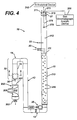
- FIG. 4 illustrates another on-line sparging sampling and monitoring system 10 with a vented waste collector assembly 200.
- the vented waste collector assembly 200 is illustrated separated from the venting and discharge tubular member 15, however in operation it is connected thereto (dashed line position).
- the vented waste collector assembly 200 comprises collector body 210, a vented waste collector inlet 201, an aqueous discharge outlet 202, and at least one spacing arrangement 205.
- the at least one spacing arrangement 205 positions the vented waste collector assembly 200 on the venting and discharge tubular member 15 in essentially a co-axial relationship.
- the vented waste collector assembly 200 is provided with an inner diameter d2 that is larger than the outer diameter d1 of the venting and discharge tubular member 15.
- Figure 5 illustrates a coaxial, annular vent space 225 that is defined by the at least one spacing arrangement 205 between the venting and discharge tubular member 15 and the vented waste collector assembly 200.
- the spacing arrangement 205 separates the vented waste collector assembly 200 from the venting and discharge tubular member 15. Therefore, a generally co-axial vent to the atmosphere is provided in the annular space 225 at a point along the on-line sparging sampling and monitoring system 10.
- the vent is disposed above an aqueous discharge flow path through the on-line sparging sampling and monitoring system 10.
- the vent space can provide atmospheric pressure and relief to the on-line sparging sampling and monitoring system 10 and prevent obstruction of the flow through the on-line sparging sampling and monitoring system 10.
- the vented waste collector assembly 200 and the outlet 202 of the vented waste collector assembly 200 be formed of similar material as the tubular members of the on-line sparging sampling and monitoring system 10.
- the outlet 202 may be provided as a single, integrally formed unit with the vented waste collector assembly 200.
- the outlet 202 can be provided as a separate component from the vented waste collector assembly 200 and connected thereto by an appropriate connector.
- the connector for the outlet 202 and the vented waste collector assembly 200 may comprise a connector as described above.
- FIG. 6 is a graph of hydrocarbon concentration data versus time that has been analyzed by an analytical device connected to a MOS sensor and gas chromatography.
- Figure 6 illustrates that the on-line sparging sampling and monitoring system 10 can monitor widely fluctuating VOC concentrations at about 1 minute intervals with a MOS sensor.
- the graph also illustrates that the data density is improved relative to the gas chromatography process.
- Figure 7 is a graph of toluene concentration data versus time that has been analyzed by an analytical device connected to a MOS sensor and gas chromatography.
- Figure 7 illustrates similar results with a micro-gas chromatography unit at about 8-minute analysis intervals.
- the on-line sparging sampling and monitoring system 10 can provide enhanced monitoring precision for both polar and non-polar hydrocarbons compared to conventional static headspace techniques alone.
- the on-line sparging sampling and monitoring system 10 provides sampling of both non-polar and polar VOCs together without separate monitoring setups.
- the on-line sparging sampling and monitoring system 10 can be configured for real-time monitoring and can be coupled to continuous or automated process analyzers.
- the on-line sparging sampling and monitoring system 10 can provide real-time data for process control and feedback, without time delays experienced by conventional sampling and monitoring systems.
- the design of the on-line sparging sampling and monitoring system 10 can be scaled to accommodate a wide range of influent flow rates.
- the tubular members and connections of the on-line sparging sampling and monitoring system 10 can be configured with dimensions that are sufficient to reduce fouling and blockage by sediments or particulates. Thus, filtering of influent aqueous discharge is avoided.
- the on-line sparging sampling and monitoring system 10 also provides for an essentially constant volume of aqueous discharge portion 113, in which the P-trap tubular member 115 can assist in maintaining a volume in the on-line sparging sampling and monitoring system 10 essentially constant. Therefore, influent aqueous discharge variations do not adversely influence the on-line sparging sampling and monitoring system 10.
Landscapes
- Health & Medical Sciences (AREA)
- Life Sciences & Earth Sciences (AREA)
- Chemical & Material Sciences (AREA)
- Engineering & Computer Science (AREA)
- Pathology (AREA)
- Physics & Mathematics (AREA)
- Analytical Chemistry (AREA)
- Biochemistry (AREA)
- General Health & Medical Sciences (AREA)
- General Physics & Mathematics (AREA)
- Immunology (AREA)
- Medicinal Chemistry (AREA)
- Food Science & Technology (AREA)
- Biomedical Technology (AREA)
- Molecular Biology (AREA)
- Combustion & Propulsion (AREA)
- Sampling And Sample Adjustment (AREA)
Abstract
Description
- The invention relates to sampling and monitoring systems and methods. In particular, the invention relates to on-line sparging sampling and monitoring systems and methods.
- Typically, a sampling system is used to monitor manufacturing processes, in which the sampling system may include analyzing capabilities. The sampling system should obtain a representative sample with minimal operations and time. While such sampling systems have been used in industry, these sampling systems may experience analytical problems, some of which may be attributed to sampling system features and mechanics.
- Manufacturing processes may produce by-products, which need monitoring, such as by sampling and analyzing. A manufacturing process may produce volatile organic compound (VOCs) by-products at a process discharge, such as, but not limited to, an aqueous discharge. Typically, VOCs can comprise mixtures of polar and non-polar hydrocarbons. VOCs can pose analytical problems for conventional monitoring and sampling systems. Polar and non-polar hydrocarbons generally require two different and distinct processes for sampling from an aqueous discharge. Non-polar VOCs, such as, but not limited to, benzene, toluene, and aliphatic hydrocarbons including hexane, are generally sampled with a purge-and-trap method and analyzed by gas chromatography (gc). However, polar VOCs, including but not limited to acetone, methanol, and other alcohols, are typically sampled by sparging or dynamic headspace sampling and analyzed by gas chromatography. Alternatively, polar VOCs can be sampled by direct injection gas chromatography (gc).
- If a monitoring system requires collection of samples (often known as "grab samples"), time delays between the actual sampling operation and the analyzing of the samples often occur. These time delays may be so long that the value of a sample is diminished because the by-product sample may not be reflective of actual and real-time by-products. Thus, the time delay is undesirable.
- Further, the aqueous discharge being monitored may often contain sediment and particulates. Conduits in conventional sampling systems may be configured too narrowly and be constricted so that fouling and blockage by sediments or particulates often occurs and interrupts monitoring. Thus, filtering of influent aqueous discharge is needed. The filters in conventional monitoring systems need to be cleaned and replaced, which is both inefficient and un-economical.
- Improvements and advancements have been proposed for sampling systems. For example, advancements have been made in on-line sampling systems including, but not limited to, sample validation techniques, modular designs, new sampling system materials, probe enhancements including fiber-optic probes, enhanced membrane technology, and re-designed valves and filters. These on-line sampling system advancements have been useful. However, if these on-line sampling system advancements are applied to old sampling system technology, analytical problems may still arise since the sampling system is limited by the old sampling system technology of the on-line sampling system.
- Therefore, improvements in on-line sampling technology are needed to keep up with current process analyzer technology. Further, a sampling system that is able to sample and monitor polar and non-polar VOCs is needed. Furthermore, a sampling system that is able to sample and monitor without delays, which are associated with some conventional sampling systems, is needed
- An aspect of the invention provides an on-line sparging sampling system and method that sparges polar and non-polar volatile organic compounds from aqueous discharge. The system comprises a network of tubular members that are interconnected to each other to define a fluid passage, in which the network of tubular members comprises an inlet for influent aqueous discharge into the network of tubular members and an outlet for discharge of aqueous discharge from the on-line sparging sampling and monitoring system; a sparger disposed in the network of tubular members, in which the sparger is disposed between the inlet and the outlet of the aqueous discharge so that aqueous discharge flows by the sparger, the sparger providing inert non-reactive gas to the on-line sparging sampling and monitoring system; and at least one analytic device connected to the on-line sparging sampling and monitoring system for analyzing volatile organic compounds in the aqueous discharge. The aqueous discharge forms an aqueous discharge portion and a headspace during flow through the network of tubular members. The sparger provides the inert non-reactive gas to flow through the aqueous discharge portion. The inert non-reactive gas partitions volatile organic compounds from the aqueous discharge portion to the headspace. Thus, polar and non-polar volatile organic compounds can be analyzed by the at least one analytic device.
- Another aspect of the invention sets forth a method for on-line sparge sampling by sparging polar and non-polar volatile organic compounds from aqueous discharge using an on-line sparging sampling and monitoring system. The method comprises providing a network of tubular members that are interconnected to each other to define a fluid passage; providing an inlet for influent aqueous discharge into the network of tubular members and an outlet for discharge from the on-line sparging sampling and monitoring system; disposing a sparger between the inlet and the outlet of the aqueous discharge; flowing aqueous discharge by the sparger; providing inert non-reactive gas from the sparger to flow through the aqueous discharge in the on-line sparging sampling and monitoring system; flowing the inert gas through the aqueous discharge; forming an aqueous discharge portion and a headspace in the network of tubular members during aqueous discharge flow through the network of tubular members; monitoring and analyzing the sparged aqueous discharge in the on-line sparging sampling and monitoring system for volatile organic compounds using at least one analytic device; and partitioning volatile organic compounds from the aqueous discharge portion to the headspace so that polar and non-polar volatile organic compounds can be analyzed.
- These and other aspects, advantages and salient features of the invention will become apparent from the following detailed description, which, when taken in conjunction with the annexed drawings, where like parts are designated by like reference characters throughout the drawings, disclose embodiments of the invention.
-
- Figure 1 is a schematic part-sectional illustration of an exemplary on-line sparging sampling and monitoring system, as embodied by the invention;
- Figure 2 is a schematic part-sectional illustration of a sparger, as embodied by the invention;
- Figure 3 is a block diagram of a sparging sampling and monitoring system, as embodied by the invention, connected to analytic and communication devices;
- Figure 4 is a schematic part-sectional illustration of another exemplary on-line sparging sampling and monitoring system, as embodied by the invention;
- Figure 5 is a sectional illustration of a vented waste collector assembly for an on-line sparging sampling and monitoring system along line 5-5 of Fig. 4;
- Figure 6 is a graph of hydrocarbon concentration versus time for monitoring, as embodied by the invention; and
- Figure 7 is a graph of toluene concentration versus time for monitoring, as embodied by the invention.
-
- An on-line sparging (dynamic headspace) sampling and monitoring system, as embodied by the invention, sparges both non-polar and polar volatile organic compounds (VOCs) from an aqueous stream. The on-line sparging sampling and monitoring system comprises features that provide robustness to the sampling system. The term robustness means that a long-term performance of the system occurs with little or no upkeep or maintenance, and is not typically prone to failure. The on-line sparging sampling and monitoring system features also reduce maintenance time and costs typically associated with conventional sampling systems. The on-line sparging sampling and monitoring system, as embodied by the invention, is configured to avoid sample conditioning, such as filtering, to remove particulates and sediments. These particulates and sediments were believed to foul and lead to sampling and analyzer systems malfunctions and repair or replacement of the filters.
- Figure 1 is an illustration of an exemplary on-line sparging sampling and
monitoring system 10. In Fig. 1, the on-line sparging sampling andmonitoring system 10 comprises a network of interconnected tubular members for transporting discharge for monitoring. The on-line sparging sampling andmonitoring system 10 comprises a spargertubular member 11, a bottom connectortubular member 12, a sidetubular member 13, a P-traptubular member 14, and a venting and dischargetubular member 15. The tubular members and connections in the on-line sparging sampling andmonitoring system 10 can be configured with dimensions that are sufficient to reduce potential of fouling and blockage by sediments or particulates in aqueous discharge. Thus, filtering of influent aqueous discharge is not needed compared to conventional systems. - The sparger
tubular member 11 comprises acap 27 at one end and is connected to the connectingtubular member 12 at the other end. Thecap 27 comprises a plurality of ports for on-line sparging sampling and monitoring system components. Thecap 27 comprises acap exhaust port 271 so that pressure in the spargertubular member 11 can be connected for be venting to the atmosphere. Thecap exhaust port 271 may be vented, connected to an exhaust treatment system, or connected to a condensing system, if desired. Thecap 27 also comprises agas chromatography port 272 that permits gas chromatography of a headspace in the on-line sparging sampling andmonitoring system 10, for example micro-gas chromatography (micro-gc) in the spargertubular member 11. Further, thecap 27 comprises asensor port 273 that permits asensor lead 276 that extends from asensor 275, such as but not limited to, a metal-oxide semiconductor (MOS) sensors and sensor, to pass therealong and connected with analytic devices (as discussed hereinafter). - The sparger
tubular member 11 also includes aninlet 20 through which the influent material to be monitored and analyzed is fed. The influent material to be monitored and analyzed often comprises an aqueous discharge, and the remainder of the description of the invention will discuss the material as an aqueous discharge. However, this description is merely exemplary and is not intended to limit the invention in any manner. - The
inlet 20 is disposed in the network of tubular members and is positioned in between thecap 27 and a connection of the spargertubular member 11 to the bottomconnector tubular member 12. Theinlet 20 and on-line sparging sampling andmonitoring system 10 can comprise part of the normal waste and by-product passage for a process being monitored. Alternatively, theinlet 20 and on-line sparging sampling andmonitoring system 10 can be connected to the waste and by-product passage by an appropriate fluid connection in which representative samples of the waste and by-products can be drawn into the on-line sparging sampling andmonitoring system 10. The influent aqueous discharge establishes anaqueous discharge level 111. Aheadspace 112 is defined above theaqueous discharge level 111 in which sparged materials, such as VOCs, can be monitored. Theaqueous discharge level 111 defines anaqueous discharge portion 113 for sparging, as discussed hereinafter. - Further, the
sparger tubular member 11 comprises agas inlet 22, which is positioned above theinlet 20 so to be disposed betwwen theinlet 20 and thecap 27. Thegas inlet 22 permits inert gas, such as, but not limited to, ambient air, to enter thesparger tubular member 11. Thus, the on-line sparging sampling andmonitoring system 10 may have equalized pressures during flow without creating back pressures, siphons, vacuums, or the like. Theinert gas inlet 22 can be disposed above theaqueous discharge level 111. This positioning facilitates removal of VOCs from theheadspace 112. This removal can assist with monitoring in which at least one of process analyzers and sensors can monitor at relatively fast frequencies, such as a frequency in a range between every few seconds to every few minutes, in which a sparging rate is not sufficiently fast to reduce vapor phase sample carryover. The term "carryover" means the transfer of a vapor phase analyte from a sampling event to a subsequent sampling event. - The
sparger tubular member 11 also includes asparger 25, which is disposed close to the connection of the spargertubular member 11 to the bottomconnector tubular member 12. Thesparger 25, which will be described in further detail hereinafter with respect to Fig. 2, permits inertnon-reactive gas 250 to continuously flow through theaqueous discharge portion 113. The gas introduced into thesparger 25 is inert to avoid any reactions with VOCs and other materials in the aqueous discharge that may adversely influence the analysis. Exemplary gases that can be introduced into the on-line sparging sampling andmonitoring system 10 at thesparger 25 include, but are not limited to, air and nitrogen. - The tubular members of the on-line sparging sampling and
monitoring system 10 comprise any appropriate material for fluid flow, in which the materials will not be degraded, corroded, or otherwise adversely affected by the aqueous discharge. For example, and in no way limiting of the invention, tubular members for the on-line sparging sampling andmonitoring system 10 may comprise polyvinyl chloride (PVC). Other non-reactive inert materials, including thick-walled glass, acrylic, and other clear polymer resins to allow for visual inspection, may also be used for the on-line sparging sampling andmonitoring system 10 features. These clear materials allow for visual inspection of the on-line sparging sampling andmonitoring system 10. - The on-line sparging sampling and
monitoring system 10 may use a single material for the tubular members, and alternatively, the on-line sparging sampling andmonitoring system 10 may use a plurality of materials for the tubular members. Further, the tubular members can be connected in any appropriate manner that is sufficient to provide fluid flow therein. For example, and in no way limiting of the invention, each of the tubular members may be threadedly connected to adjacent tubular members. Alternatively, the each of the tubular members may be connected by other connections, such as glued to adjacent tubular members. These types of connections are merely exemplary and are not intended to limit the invention in any manner. The connectors betwwen the tubular members can comprise stainless steel connections, PVC connections, nylon connections, high-density polyethylene (HDPE) connections, and like material. - The features that are connected to the on-line sparging sampling and
monitoring system 10, such as, but not limited to, thesparger 25, theinlet 20, thecap 27, and theair inlet 22 may be connected to the on-line sparging sampling andmonitoring system 10 by any appropriate manner that is sufficient to provide fluid flow therein. For example, and in no way limiting of the invention, each of the features may be threadedly connected to the respective tubular members. Alternatively, the each of these features may be connected to the respective tubular members by other connections, such as glued to the respective adjacent tubular members. These types of connections are merely exemplary and are not intended to limit the invention in any manner. - The aqueous discharge level in the on-line sparging sampling and
monitoring system 10 can controlled at a level by the P-trap tubular member 14 and venting and dischargetubular member 15. The venting and dischargetubular member 15 comprises a vent to the atmosphere, which is generally illustrated as 32, at some point along the on-line sparging sampling andmonitoring system 10 above an aqueous discharge flow path through the on-line sparging sampling andmonitoring system 10. Thus, thevent 32 can provide atmospheric pressure and relief to the on-line sparging sampling andmonitoring system 10 and prevent obstruction of the flow. - The configuration of the
vent 32, the venting and dischargetubular member 15, and the on-line sparging sampling andmonitoring system 10, allows an aqueous discharge volume 113 (Fig. 1), which is being sparged in the on-line sparging sampling andmonitoring system 10, to remain essentially constant. The term "essentially" is used with its conventional meaning in which the volume remains the same and may undergo minor changes that do not influence the operation or results of the on-line sparging sampling andmonitoring system 10. The volume of theaqueous discharge portion 113 can remain essentially constant, even if the influent aqueous discharge flow varies over time. If the aqueous discharge influent flow through theinlet 20 were to stop, the sparging would result in a steady decline in VOCs entering a headspace above the water column. - Figure 2 is an exploded illustration of the
sparger 25 for the on-line sparging sampling andmonitoring system 10, as embodied by the invention. Thesparger 25 is connected to thesparger tubular member 11 at a lower end of the spargertubular member 11. The connection of thesparger 25 to thesparger tubular member 11 is illustrated with a threaded connection, withthreads 251 on thesparger 25 andthreads 117 on thesparger tubular member 11. Thesparger 25 further comprises afilter disc 252, for example a porous disc with about 2-micron openings therein for the passage of the gas. The diameter of thefilter disc 252 is selected to approximately match a diameter of the spargertubular member 11 andaqueous discharge portion 113 therein. Thefilter disc 252 is formed of a material selected from stainless steel, glass, polytetrafluoroethylene, and combinations thereof. - The
sparger 25 further comprises abody 253 and a further threadedconnection 254 that can permit thesparger 25 to be connected to the source of gas for sparging. The connection of thesparger 25 to thesparger tubular member 11 disposes thesparger 25 in a generally parallel configuration to the flow of aqueous discharge. Therefore, the parallel configuration will prevent particulate matter and sediments in the aqueous discharge from depositing on thesparger 25. This parallel configuration can reduce fouling and maintenance of thesparger 25 and on-line sparging sampling andmonitoring system 10. Thesparger 25 can be easily removed from thesparger tubular member 11 by the threaded connection at 251 and 117 respectively. This threaded connection allows removal, cleaning, and replacement of thesparger 25 if desired. - The sparging rate for the water column is provided at a rate that is sufficient to partition VOC(s) from the
aqueous discharge portion 113 to theheadspace 112 above theaqueous discharge portion 113. Theheadspace 112 is closed by thecap 27, which as discussed above, comprises ports through which analytic devices can be coupled to theheadspace 112, These analytic devices can comprise, but are not limited to, agas chromatography device 300, which is illustrated as being connected throughport 272, and asensor 275 basedanalytic device 310, which extends into theheadspace 112 by alead 276. These ports and devices connected are merely exemplary and are not intended to limit the invention in any manner. - At least a part of the
aqueous discharge portion 113 in thesparger tubular member 11 may be heated to facilitate partitioning of VOCs to theheadspace 112. Any appropriate device may conduct the heating of theaqueous discharge portion 113. The heating of theaqueous discharge portion 111 can also reduce variations in partitioning efficiencies, for example if there are temperature changes in the environment of the on-line sparging sampling andmonitoring system 10. - The analytic devices, 300 and 310, that are connected to the on-line sparging sampling and
monitoring system 10 can be selected from a variety of available process analyzers. For example, aMOS sensor 275 and micro-gas chromatography sampler in the on-line sparging sampling andmonitoring system 10, when coupled to theheadspace portion 112 and connected to the analytic devices, can provide near real-time monitoring and analyzing. The term "real-time" is used with its accepted meaning in the art. For example, theMOS sensor 275 can deliver total hydrocarbon concentration data at response times of about 1 second. Further, micro-micro-gas chromatography systems can provide VOC data at response times of about 6 minutes. - The on-line sparging sampling and
monitoring system 10 can be connected to communication links for providing the analyzed data to those authorized parties or users of the on-line sparging sampling andmonitoring system 10. For example, Fig. 3 illustrates a block diagram of the on-line sparging sampling andmonitoring system 10 connected tovarious users 320 via communication links 301. Further, the information from the analytic devices can be transferred directly to a party, for example by communication link 301'. Alternatively, information from the analytic devices can be transferred directly to a party, for example bycommunication links 301 that lead to a commondata gathering location 305, such as, but not limited to, a web page. The communication links 301 include, but are not limited to include, at least one of a phone modem, network connection, communication, radio communication and other wireless communication systems, cellular communication, satellite communication, web access communication, and Internet access communication, and combinations thereof. - The use of a web page provides real-time monitoring and analysis data to
parties 320 who can readily benefit from the information. In the past, evaluations occurred randomly, irregularly, and may not normally be transmitted in an expedited manner. With the on-line sparging sampling andmonitoring system 10, as embodied by the invention, parties that are actually located at the on-line sparging sampling andmonitoring system 10 can quickly obtain analyzed and evaluated information, which is provided in a form that is valuable and easy to use. Also,other parties 320 that may not be located at the on-line sparging sampling andmonitoring system 10, for example but not limited to regulatory agencies, can also obtain monitored data in real-time, so as to avoid undesirable time delays. With the real-time monitored data, aparty 320 may take immediate steps in response to the data. Also, with the real-time monitored data via the web, feedback from a party can be provided and received via the web. - Figure 4 illustrates another on-line sparging sampling and
monitoring system 10 with a ventedwaste collector assembly 200. In Fig. 4, features of the on-line sparging sampling andmonitoring system 10 as discussed above are provided with like reference numbers. Fig. 4, the ventedwaste collector assembly 200 is illustrated separated from the venting and dischargetubular member 15, however in operation it is connected thereto (dashed line position). The ventedwaste collector assembly 200 comprisescollector body 210, a ventedwaste collector inlet 201, anaqueous discharge outlet 202, and at least onespacing arrangement 205. The at least onespacing arrangement 205 positions the ventedwaste collector assembly 200 on the venting and dischargetubular member 15 in essentially a co-axial relationship. The ventedwaste collector assembly 200 is provided with an inner diameter d2 that is larger than the outer diameter d1 of the venting and dischargetubular member 15. - Figure 5 illustrates a coaxial,
annular vent space 225 that is defined by the at least onespacing arrangement 205 between the venting and dischargetubular member 15 and the ventedwaste collector assembly 200. Thespacing arrangement 205 separates the ventedwaste collector assembly 200 from the venting and dischargetubular member 15. Therefore, a generally co-axial vent to the atmosphere is provided in theannular space 225 at a point along the on-line sparging sampling andmonitoring system 10. The vent is disposed above an aqueous discharge flow path through the on-line sparging sampling andmonitoring system 10. Thus, the vent space can provide atmospheric pressure and relief to the on-line sparging sampling andmonitoring system 10 and prevent obstruction of the flow through the on-line sparging sampling andmonitoring system 10. - The vented
waste collector assembly 200 and theoutlet 202 of the ventedwaste collector assembly 200, as embodied by the invention, be formed of similar material as the tubular members of the on-line sparging sampling andmonitoring system 10. Theoutlet 202 may be provided as a single, integrally formed unit with the ventedwaste collector assembly 200. Alternatively, theoutlet 202 can be provided as a separate component from the ventedwaste collector assembly 200 and connected thereto by an appropriate connector. The connector for theoutlet 202 and the ventedwaste collector assembly 200 may comprise a connector as described above. - Exemplary sensor information and data outputs from an on-line sparging sampling and
monitoring system 10, as embodied by the invention, are illustrated in Figs. 6 and 7. Figure 6 is a graph of hydrocarbon concentration data versus time that has been analyzed by an analytical device connected to a MOS sensor and gas chromatography. Figure 6 illustrates that the on-line sparging sampling andmonitoring system 10 can monitor widely fluctuating VOC concentrations at about 1 minute intervals with a MOS sensor. The graph also illustrates that the data density is improved relative to the gas chromatography process. Figure 7 is a graph of toluene concentration data versus time that has been analyzed by an analytical device connected to a MOS sensor and gas chromatography. Figure 7 illustrates similar results with a micro-gas chromatography unit at about 8-minute analysis intervals. - The on-line sparging sampling and
monitoring system 10, as embodied by the invention, can provide enhanced monitoring precision for both polar and non-polar hydrocarbons compared to conventional static headspace techniques alone. The on-line sparging sampling andmonitoring system 10 provides sampling of both non-polar and polar VOCs together without separate monitoring setups. Further, the on-line sparging sampling andmonitoring system 10 can be configured for real-time monitoring and can be coupled to continuous or automated process analyzers. Thus, the on-line sparging sampling andmonitoring system 10 can provide real-time data for process control and feedback, without time delays experienced by conventional sampling and monitoring systems. - Further, the design of the on-line sparging sampling and
monitoring system 10 can be scaled to accommodate a wide range of influent flow rates. The tubular members and connections of the on-line sparging sampling andmonitoring system 10 can be configured with dimensions that are sufficient to reduce fouling and blockage by sediments or particulates. Thus, filtering of influent aqueous discharge is avoided. The on-line sparging sampling andmonitoring system 10 also provides for an essentially constant volume ofaqueous discharge portion 113, in which the P-trap tubular member 115 can assist in maintaining a volume in the on-line sparging sampling andmonitoring system 10 essentially constant. Therefore, influent aqueous discharge variations do not adversely influence the on-line sparging sampling andmonitoring system 10. - While various embodiments are described herein, it will be appreciated from the specification that various combinations of elements, variations or improvements therein may be made by those skilled in the art, and are within the scope of the invention.
Claims (23)
- An on-line sparging sampling system for sparging polar and non-polar volatile organic compounds from aqueous discharge, the system comprising:a network of tubular members (11, 12, 13, 14, 15) that are interconnected to each other to define a fluid passage, the network of tubular members comprising an inlet (20) for influent aqueous discharge into the network of tubular members and an outlet (30) for discharge of aqueous discharge from the on-line sparging sampling and monitoring system;a sparger (25) disposed in the network of tubular members, the sparger being disposed between the inlet and the outlet of the aqueous discharge so that aqueous discharge flows by the sparger, the sparger providing inert non-reactive gas to the on-line sparging sampling and monitoring system; andat least one analytic device (310) connected to the on-line sparging sampling and monitoring system for analyzing volatile organic compounds in the aqueous discharge;wherein the aqueous discharge forms a aqueous discharge portion and a headspace during flow through the network of tubular members, the sparger providing the inert non-reactive gas to flow through the aqueous discharge portion, the inert non-reactive gas partitioning volatile organic compounds from the aqueous discharge portion to the headspace so that polar and non-polar volatile organic compounds can be analyzed by the at least one analytic device.
- A system according to claim 1, wherein the network of tubular members comprises at least a sparger tubular member (11), a bottom connector tubular member (12), a side tubular member (13), a P-trap tubular member (14), and a venting and discharge tubular member (15).
- A system according to claim 2, wherein the sparger (25) is disposed in the sparger tubular member proximate the bottom connector tubular member (12).
- A system according to claim 3, wherein the sparger (25) is disposed essentially in parallel with a flow of aqueous discharge in the on-line sparging sampling and monitoring system.
- A system according to claim 2, wherein the network of tubular members comprise a size sufficient to remain open with a flow of particulate and sediment ladened aqueous discharge.
- A system according to claim 2, wherein the venting and discharge tubular member (15) comprises the outlet.
- A system according to claim 2, wherein the venting and discharge tubular member (15) comprises a vent, the vent providing atmospheric pressure to the on-line sparging sampling and monitoring system to prevent flow stoppage.
- A system according to claim 2, wherein the sparger tubular member (11) comprises a gas inlet for adding inert gas to the on-line sparging sampling and monitoring system, the inert gas inlet being disposed in the headspace and providing sufficient pressure to essentially equalize pressure in the on-line sparging sampling and monitoring system during flow.
- A system according to claim 2, wherein the sparger tubular member comprises a cap (27) on one end proximate the headspace, the at least one analytic device communicating with the headspace through the cap.
- A system according to claim 9, wherein the cap comprises at least one port that allows communication of the at least one analytic device with the headspace.
- A system according to claim 9, wherein the at least one analytic device comprises at least one of a gas chromatography device (300) and a MOS sensor analytic device, and the cap comprises individual ports for each analytic device.
- A system according to claim 9, wherein the cap comprises an exhaust vent port (271) that allows gases in the headspace to be exhausted.
- A system according to claim 12, wherein the exhaust vent port communicates gases in the headspace to at least one of the atmosphere, a condenser, and an exhaust gas treatment system.
- A system according to any preceding claim, wherein the at least one analytic device comprises at least one of a gas chromatography device and a MOS sensor analytic device.
- A system according to any preceding claim, wherein the sparger (25) comprises a threaded connection to the network of tubular members, the sparger being disposed in an essentially parallel orientation to the flow in the network of tubular members.
- A system according to any preceding claim, wherein the sparger (25) comprises a filter disc (252) for passing gas into the aqueous discharge, in which the gas comprises an inert gas for sparging volatile organic compounds from the aqueous discharge to the headspace.
- A system according to any preceding claim, wherein the outlet comprises a vented waste collector assembly (200), the vented waste collector assembly comprising a vent assembly for venting the on-line sparging sampling and monitoring system and the outlet.
- A system according to claim 17, wherein the vented waste collector assembly comprises a collector body (210), a collector inlet (201), an outlet (202), and at least one spacing arrangement (225) for spacing the vented waste collector assembly from the network of tubular members.
- A system according to claim 18, wherein the spacing arrangement co-axially disposes the collector body on the network of tubular members to define a annular vent space between the vented waste collector assembly and the network of tubular members.
- A system according to any preceding claim, further comprising at least one communication link (301) that connects the on-line sparging sampling and monitoring system to at least one party, wherein the communication link comprises at least one of a phone modem, network connection, communication, radio communication and other wireless communication systems, cellular communication, satellite communication, web access communication, and Internet access communication, and combinations thereof.
- A system according to any preceding claim, further comprising at least one communication link (301) that connects the on-line sparging sampling and monitoring system to at least one party, wherein the communication link comprises Internet access communication.
- A system according to any preceding claim, further comprising at least one communication link (301) that connects the on-line sparging sampling and monitoring system to provide real-time data to at least one party.
- A method for on-line sparge sampling by sparging polar and non-polar volatile organic compounds from aqueous discharge using an on-line sparging sampling and monitoring system, the method comprising:providing a network of tubular members (11, 12, 13, 14, 15) that are interconnected to each other to define a fluid passage;providing an inlet (20) for influent aqueous discharge into the network of tubular members and an outlet (30) for discharge from the on-line sparging sampling and monitoring system;disposing a sparger (25) between the inlet and the outlet of the aqueous discharge;flowing aqueous discharge by the sparger;providing inert non-reactive gas from the sparger to flow through the aqueous discharge in the on-line sparging sampling and monitoring system;flowing the inert gas through the aqueous discharge;forming an aqueous discharge portion and a headspace in the network of tubular members during aqueous discharge flow through the network of tubular members;monitoring and analyzing the sparged aqueous discharge in the on-line sparging sampling and monitoring system for volatile organic compounds using at least one analytic device; andpartitioning volatile organic compounds from the aqueous discharge portion to the headspace so that polar and non-polar volatile organic compounds can be analyzed.
Applications Claiming Priority (2)
| Application Number | Priority Date | Filing Date | Title |
|---|---|---|---|
| US09/556,288 US6485688B1 (en) | 2000-04-24 | 2000-04-24 | On-line sparging sampling and monitoring systems and methods |
| US556288 | 2000-04-24 |
Publications (1)
| Publication Number | Publication Date |
|---|---|
| EP1150112A1 true EP1150112A1 (en) | 2001-10-31 |
Family
ID=24220702
Family Applications (1)
| Application Number | Title | Priority Date | Filing Date |
|---|---|---|---|
| EP01303625A Withdrawn EP1150112A1 (en) | 2000-04-24 | 2001-04-20 | On-line sparging sampling and monitoring devices and methods |
Country Status (3)
| Country | Link |
|---|---|
| US (1) | US6485688B1 (en) |
| EP (1) | EP1150112A1 (en) |
| JP (1) | JP2002039925A (en) |
Cited By (2)
| Publication number | Priority date | Publication date | Assignee | Title |
|---|---|---|---|---|
| EP1167945B1 (en) * | 2000-06-28 | 2006-10-04 | Institut Francais Du Petrole | Transport device for analysing hydrocarbon constituents |
| CN110426480A (en) * | 2019-09-10 | 2019-11-08 | 中绿环保科技股份有限公司 | A kind of real time on-line monitoring equipment of water quality volatile organic matter |
Families Citing this family (20)
| Publication number | Priority date | Publication date | Assignee | Title |
|---|---|---|---|---|
| FR2829945B1 (en) * | 2001-09-25 | 2003-10-31 | Geoservices | MODULE FOR EXTRACTING GAS FROM A BASEMENT LIQUID AND INSTALLATION PROVIDED WITH THE MODULE |
| US20040083889A1 (en) * | 2002-11-05 | 2004-05-06 | Rawls Nathan C. | Immersion heater for sparge vessel |
| US20050064076A1 (en) * | 2003-09-22 | 2005-03-24 | Fmc Technologies, Inc. | Method of measuring volatile components of foods |
| US7058089B2 (en) * | 2004-02-18 | 2006-06-06 | Rosemount, Inc. | System and method for maintaining a common sense of time on a network segment |
| US7234084B2 (en) * | 2004-02-18 | 2007-06-19 | Emerson Process Management | System and method for associating a DLPDU received by an interface chip with a data measurement made by an external circuit |
| ES2369311T3 (en) | 2008-04-18 | 2011-11-29 | Basf Se | TEMPERATE OF A PRODUCT TO BE MEASURED IN A DEPLOYER THROUGH A DIRECT STEAM INJECTION. |
| BR112014031842B1 (en) | 2012-06-21 | 2020-09-15 | Baxalta GmbH | METHOD FOR REMOVING A VIRAL CONTAMINANT FROM PREPARATION |
| FR3060124B1 (en) * | 2016-12-08 | 2022-03-11 | Suez Groupe | METHOD FOR CONTROLLING THE CONCENTRATION OF ORGANIC COMPOUNDS IN A FLUID OF A FLUID NETWORK |
| US10717056B1 (en) | 2019-09-09 | 2020-07-21 | Michael Cem Gokay | Method and apparatus for purification of cannabinoid extracts |
| US11932080B2 (en) | 2020-08-20 | 2024-03-19 | Denso International America, Inc. | Diagnostic and recirculation control systems and methods |
| US12017506B2 (en) | 2020-08-20 | 2024-06-25 | Denso International America, Inc. | Passenger cabin air control systems and methods |
| US11881093B2 (en) | 2020-08-20 | 2024-01-23 | Denso International America, Inc. | Systems and methods for identifying smoking in vehicles |
| US12251991B2 (en) | 2020-08-20 | 2025-03-18 | Denso International America, Inc. | Humidity control for olfaction sensors |
| US11636870B2 (en) | 2020-08-20 | 2023-04-25 | Denso International America, Inc. | Smoking cessation systems and methods |
| US11828210B2 (en) | 2020-08-20 | 2023-11-28 | Denso International America, Inc. | Diagnostic systems and methods of vehicles using olfaction |
| US12269315B2 (en) | 2020-08-20 | 2025-04-08 | Denso International America, Inc. | Systems and methods for measuring and managing odor brought into rental vehicles |
| US11760170B2 (en) | 2020-08-20 | 2023-09-19 | Denso International America, Inc. | Olfaction sensor preservation systems and methods |
| US11760169B2 (en) | 2020-08-20 | 2023-09-19 | Denso International America, Inc. | Particulate control systems and methods for olfaction sensors |
| US11813926B2 (en) | 2020-08-20 | 2023-11-14 | Denso International America, Inc. | Binding agent and olfaction sensor |
| US12377711B2 (en) | 2020-08-20 | 2025-08-05 | Denso International America, Inc. | Vehicle feature control systems and methods based on smoking |
Citations (5)
| Publication number | Priority date | Publication date | Assignee | Title |
|---|---|---|---|---|
| DE3900799A1 (en) * | 1988-08-05 | 1990-06-07 | Meta Messtechnische Systeme Gm | Measuring apparatus for determining volatile constituents in a liquid by the headspace method |
| DE4007064A1 (en) * | 1990-03-07 | 1991-09-12 | Bayer Ag | DEVICE FOR DETERMINING VOLATILE SUBSTANCES IN A LIQUID |
| WO1992008118A1 (en) * | 1990-10-26 | 1992-05-14 | E.I. Du Pont De Nemours And Company | System and method for monitoring the concentration of volatile material dissolved in a liquid |
| WO1999019726A1 (en) * | 1997-10-16 | 1999-04-22 | Isco, Inc. | Hydrogen sulfide analyzer |
| JP2000028617A (en) * | 1998-07-14 | 2000-01-28 | Horiba Ltd | Analysis system |
Family Cites Families (10)
| Publication number | Priority date | Publication date | Assignee | Title |
|---|---|---|---|---|
| US3550917A (en) * | 1968-12-31 | 1970-12-29 | Multi Minerals Ltd | Gas sparging mechanism |
| US5080868A (en) * | 1990-05-16 | 1992-01-14 | Elgas David H | Sparger assembly |
| US5122166A (en) * | 1990-07-10 | 1992-06-16 | International Environmental Systems, Inc. | Removal of volatile compounds and surfactants from liquid |
| US5421194A (en) * | 1991-03-01 | 1995-06-06 | Axiom Analytical, Inc. | Liquid quality analysis system combining sparging and an infrared gas cell |
| US5531904A (en) * | 1995-03-20 | 1996-07-02 | Revtech Industries, Inc. | Gas sparging method for removing volatile contaminants from liquids |
| US5693538A (en) * | 1995-08-31 | 1997-12-02 | Olin Corporation | System and method for monitoring volatile species in liquids |
| US5909368A (en) * | 1996-04-12 | 1999-06-01 | Fisher-Rosemount Systems, Inc. | Process control system using a process control strategy distributed among multiple control elements |
| US5646336A (en) * | 1996-05-10 | 1997-07-08 | Lockheed Martin Energy Systems, Inc. | Atomizing, continuous, water monitoring module |
| US6123750A (en) * | 1998-10-30 | 2000-09-26 | New England Radon, Ltd | Spray and aeration system for removing volatile compounds |
| US6298454B1 (en) * | 1999-02-22 | 2001-10-02 | Fisher-Rosemount Systems, Inc. | Diagnostics in a process control system |
-
2000
- 2000-04-24 US US09/556,288 patent/US6485688B1/en not_active Expired - Fee Related
-
2001
- 2001-04-20 EP EP01303625A patent/EP1150112A1/en not_active Withdrawn
- 2001-04-23 JP JP2001123741A patent/JP2002039925A/en not_active Withdrawn
Patent Citations (5)
| Publication number | Priority date | Publication date | Assignee | Title |
|---|---|---|---|---|
| DE3900799A1 (en) * | 1988-08-05 | 1990-06-07 | Meta Messtechnische Systeme Gm | Measuring apparatus for determining volatile constituents in a liquid by the headspace method |
| DE4007064A1 (en) * | 1990-03-07 | 1991-09-12 | Bayer Ag | DEVICE FOR DETERMINING VOLATILE SUBSTANCES IN A LIQUID |
| WO1992008118A1 (en) * | 1990-10-26 | 1992-05-14 | E.I. Du Pont De Nemours And Company | System and method for monitoring the concentration of volatile material dissolved in a liquid |
| WO1999019726A1 (en) * | 1997-10-16 | 1999-04-22 | Isco, Inc. | Hydrogen sulfide analyzer |
| JP2000028617A (en) * | 1998-07-14 | 2000-01-28 | Horiba Ltd | Analysis system |
Non-Patent Citations (1)
| Title |
|---|
| PATENT ABSTRACTS OF JAPAN vol. 2000, no. 04 31 August 2000 (2000-08-31) * |
Cited By (2)
| Publication number | Priority date | Publication date | Assignee | Title |
|---|---|---|---|---|
| EP1167945B1 (en) * | 2000-06-28 | 2006-10-04 | Institut Francais Du Petrole | Transport device for analysing hydrocarbon constituents |
| CN110426480A (en) * | 2019-09-10 | 2019-11-08 | 中绿环保科技股份有限公司 | A kind of real time on-line monitoring equipment of water quality volatile organic matter |
Also Published As
| Publication number | Publication date |
|---|---|
| US6485688B1 (en) | 2002-11-26 |
| JP2002039925A (en) | 2002-02-06 |
Similar Documents
| Publication | Publication Date | Title |
|---|---|---|
| US6485688B1 (en) | On-line sparging sampling and monitoring systems and methods | |
| US6491828B1 (en) | Method and system to remotely monitor groundwater treatment | |
| EP1322934B1 (en) | Sampler for collecting particles from air | |
| US6451210B1 (en) | Method and system to remotely monitor a carbon adsorption process | |
| US5317932A (en) | Sample probe | |
| EP1711806B1 (en) | Gas chromatograph with column comprising open tubular capillaries | |
| US6436710B1 (en) | Headspace sampling and monitoring systems and methods | |
| US5047073A (en) | Sorption separation apparatus and methods | |
| US20040149007A1 (en) | Sample handling system with solvent washing | |
| US6021678A (en) | Apparatus for transporting emissions from a stack | |
| US5233876A (en) | Apparatus and methods for on-line analysis of one or more process streams | |
| US5376163A (en) | Filter system | |
| US20240418687A1 (en) | Gas chromatography instrument for autonomously determining a concentration of a volatile marker in a liquid sample | |
| EP1806169A1 (en) | System and method for measuring filter saturation | |
| EP2111280A1 (en) | Separating particulate-containing gas flow into particulate and non-particulate flow portions | |
| JP2006337158A (en) | Sample concentrator | |
| Anthemidis et al. | A sequential injection lab-at-valve (SI-LAV) platform for hydride generation atomic absorption spectrometry (HG-AAS): on-line determination of inorganic arsenic | |
| US12117430B2 (en) | Device and method for partial transfer of a liquid sample, comprising multiple components and method for the online determination and analysis of these components | |
| US20080307903A1 (en) | Gas Sample Collection and Analysis | |
| JPH07209272A (en) | Gas chromatograph system | |
| EP4363825A1 (en) | System for separating an analyte from a sample | |
| US7293473B2 (en) | Method and apparatus for sampling biological particles in an air flow | |
| EP4574961A1 (en) | Bioprocess assembly with integrated filtration and sampling systems | |
| JP3034072B2 (en) | Method and apparatus for recovering a liquid sample in a continuous cycle and gas transport thereof | |
| CN112649572A (en) | Soil volatile pollutant detection drill bit and detection device of liquid early warning |
Legal Events
| Date | Code | Title | Description |
|---|---|---|---|
| PUAI | Public reference made under article 153(3) epc to a published international application that has entered the european phase |
Free format text: ORIGINAL CODE: 0009012 |
|
| AK | Designated contracting states |
Kind code of ref document: A1 Designated state(s): DE FR GB Kind code of ref document: A1 Designated state(s): AT BE CH CY DE DK ES FI FR GB GR IE IT LI LU MC NL PT SE TR |
|
| AX | Request for extension of the european patent |
Free format text: AL;LT;LV;MK;RO;SI |
|
| 17P | Request for examination filed |
Effective date: 20020502 |
|
| AKX | Designation fees paid |
Free format text: DE FR GB |
|
| STAA | Information on the status of an ep patent application or granted ep patent |
Free format text: STATUS: THE APPLICATION IS DEEMED TO BE WITHDRAWN |
|
| 18D | Application deemed to be withdrawn |
Effective date: 20071101 |