EP1149886A2 - Improved hydrocracking process - Google Patents
Improved hydrocracking process Download PDFInfo
- Publication number
- EP1149886A2 EP1149886A2 EP01109970A EP01109970A EP1149886A2 EP 1149886 A2 EP1149886 A2 EP 1149886A2 EP 01109970 A EP01109970 A EP 01109970A EP 01109970 A EP01109970 A EP 01109970A EP 1149886 A2 EP1149886 A2 EP 1149886A2
- Authority
- EP
- European Patent Office
- Prior art keywords
- stream
- zone
- hydrocarbonaceous
- hydrocracking
- boiling
- Prior art date
- Legal status (The legal status is an assumption and is not a legal conclusion. Google has not performed a legal analysis and makes no representation as to the accuracy of the status listed.)
- Granted
Links
Images
Classifications
-
- C—CHEMISTRY; METALLURGY
- C10—PETROLEUM, GAS OR COKE INDUSTRIES; TECHNICAL GASES CONTAINING CARBON MONOXIDE; FUELS; LUBRICANTS; PEAT
- C10G—CRACKING HYDROCARBON OILS; PRODUCTION OF LIQUID HYDROCARBON MIXTURES, e.g. BY DESTRUCTIVE HYDROGENATION, OLIGOMERISATION, POLYMERISATION; RECOVERY OF HYDROCARBON OILS FROM OIL-SHALE, OIL-SAND, OR GASES; REFINING MIXTURES MAINLY CONSISTING OF HYDROCARBONS; REFORMING OF NAPHTHA; MINERAL WAXES
- C10G47/00—Cracking of hydrocarbon oils, in the presence of hydrogen or hydrogen- generating compounds, to obtain lower boiling fractions
-
- C—CHEMISTRY; METALLURGY
- C10—PETROLEUM, GAS OR COKE INDUSTRIES; TECHNICAL GASES CONTAINING CARBON MONOXIDE; FUELS; LUBRICANTS; PEAT
- C10G—CRACKING HYDROCARBON OILS; PRODUCTION OF LIQUID HYDROCARBON MIXTURES, e.g. BY DESTRUCTIVE HYDROGENATION, OLIGOMERISATION, POLYMERISATION; RECOVERY OF HYDROCARBON OILS FROM OIL-SHALE, OIL-SAND, OR GASES; REFINING MIXTURES MAINLY CONSISTING OF HYDROCARBONS; REFORMING OF NAPHTHA; MINERAL WAXES
- C10G49/00—Treatment of hydrocarbon oils, in the presence of hydrogen or hydrogen-generating compounds, not provided for in a single one of groups C10G45/02, C10G45/32, C10G45/44, C10G45/58 or C10G47/00
- C10G49/10—Treatment of hydrocarbon oils, in the presence of hydrogen or hydrogen-generating compounds, not provided for in a single one of groups C10G45/02, C10G45/32, C10G45/44, C10G45/58 or C10G47/00 with moving solid particles
- C10G49/12—Treatment of hydrocarbon oils, in the presence of hydrogen or hydrogen-generating compounds, not provided for in a single one of groups C10G45/02, C10G45/32, C10G45/44, C10G45/58 or C10G47/00 with moving solid particles suspended in the oil, e.g. slurries
-
- C—CHEMISTRY; METALLURGY
- C10—PETROLEUM, GAS OR COKE INDUSTRIES; TECHNICAL GASES CONTAINING CARBON MONOXIDE; FUELS; LUBRICANTS; PEAT
- C10G—CRACKING HYDROCARBON OILS; PRODUCTION OF LIQUID HYDROCARBON MIXTURES, e.g. BY DESTRUCTIVE HYDROGENATION, OLIGOMERISATION, POLYMERISATION; RECOVERY OF HYDROCARBON OILS FROM OIL-SHALE, OIL-SAND, OR GASES; REFINING MIXTURES MAINLY CONSISTING OF HYDROCARBONS; REFORMING OF NAPHTHA; MINERAL WAXES
- C10G49/00—Treatment of hydrocarbon oils, in the presence of hydrogen or hydrogen-generating compounds, not provided for in a single one of groups C10G45/02, C10G45/32, C10G45/44, C10G45/58 or C10G47/00
- C10G49/22—Separation of effluents
Definitions
- the field of art to which this invention pertains is the hydrocracking of a hydrocarbonaceous feedstock.
- Petroleum refiners often produce desirable products such as turbine fuel, diesel fuel and other products known as middle distillates as well as lower boiling hydrocarbonaceous liquids such as naphtha and gasoline by hydrocracking a hydrocarbon feedstock derived from crude oil, for example.
- Feedstocks most often subjected to hydrocracking are gas oils and heavy gas oils recovered from crude oil by distillation.
- a typical heavy gas oil comprises a substantial portion of hydrocarbon components boiling above about 371°C (700°F), usually at least about 50 percent by weight boiling above 371°C (700°F).
- a typical vacuum gas oil normally has a boiling point range between about 315°C (600°F) and about 565°C (1050°F).
- Hydrocracking is generally accomplished by contacting in a hydrocracking reaction vessel or zone the gas oil or other feedstock to be treated with a suitable hydrocracking catalyst under conditions of elevated temperature and pressure in the presence of hydrogen so as to yield a product containing a distribution of hydrocarbon products desired by the refiner.
- a hydrocracking reaction vessel or zone the gas oil or other feedstock to be treated with a suitable hydrocracking catalyst under conditions of elevated temperature and pressure in the presence of hydrogen so as to yield a product containing a distribution of hydrocarbon products desired by the refiner.
- the operating conditions and the hydrocracking catalysts within a hydrocracking reactor influence the yield of the hydrocracked products.
- US-A-5,720,872 discloses a process for hydroprocessing liquid feedstocks in two or more hydroprocessing stages which are in separate reaction vessels and wherein each reaction stage contains a bed of hydroprocessing catalyst.
- the liquid product from the first reaction stage is sent to a low pressure stripping stage and stripped of hydrogen sulfide, ammonia and other dissolved gases.
- the stripped product stream is then sent to the next downstream reaction stage, the product from which is also stripped of dissolved gases and sent to the next downstream reaction stage until the last reaction stage, the liquid product of which is stripped of dissolved gases and collected or passed on for further processing.
- the flow of treat gas is in a direction opposite the direction in which the reaction stages are staged for the flow of liquid.
- Each stripping stage is a separate stage, but all stages are contained in the same stripper vessel.
- US-A-3,328,290 discloses a two-stage process for the hydrocracking of hydrocarbons in which the feed is pretreated in the first stage.
- US-A-5,980,729 discloses a hydrocracking process utilizing reverse staging in hydroprocessing reactor systems and a hot, high-pressure stripping zone.
- the present invention is a catalytic hydrocracking process which uses a divided-wall fractionator to recover lower boiling hydrocarbon product streams, a liquid recycle stream and a drag stream containing a high concentration of heavy polynuclear aromatic compounds.
- the process of the present invention benefits from the ability to achieve a lower capital cost, lower operating expense and simplified operation.
- Specific embodiments of the invention may provide higher liquid product yields, specifically higher yields of turbine fuel and diesel oil with a low conversion per pass operation.
- Other benefits of a low conversion per pass operation include the minimization or elimination of the need for inter-bed hydrogen quench and the minimization of the fresh feed pre-heat since the higher flow rate of recycle liquid will provide additional process heat to initiate the catalytic reaction and an additional heat sink to absorb the heat of reaction. An overall reduction in fuel gas and hydrogen consumption, and light ends production may also be obtained.
- the low conversion per pass operation requires less catalyst volume.
- the present invention relates to a process for hydrocracking a hydrocarbonaceous feedstock that passes a hydrocarbonaceous input stream and hydrogen to a hydrocracking zone containing hydrocracking catalyst to produce a hydrocracking effluent; combines a hydrocarbonaceous feedstock with at least one of the hydrocarboneous input streams or the hydrocracking effluent; separates the effluent from said hydrocracking zone in a first separation zone to produce a first stream containing hydrogen and hydrocarbons boiling at at temperature below the boiling range of said hydrocarboneous input stream and a second stream comprising hydrocarbons boiling at a temperature in the boiling range of said hydrocarbonaceous input stream and heavy polynuclear aromatic compounds; introduces at least a portion of the second stream into a second separation zone to produce a third stream comprising hydrocarbons boiling at a temperature in the boiling range of said hydrocarbonaceous input stream and heavy polynuclear aromatic compounds and a fourth stream comprising hydrocarbons boiling at a temperature equal to or below the
- the undesirable production of polynuclear aromatic compounds is controlled by removing a small dragstream of high pressure product stripper bottoms to reject polynuclear aromatic compounds and recovering valuable diesel boiling range hydrocarbons and unconverted feedstock by routing the dragstream to a hot flash separator and subsequently to a divided wall fractionation zone to produce a concentrated stream of polynuclear aromatic compounds while recovering the valuable hydrocarbon compounds.
- a divided-wall fractionation zone may be successfully utilized to produce various product streams from a hydrocracking reaction zone including, for example, naphtha, kerosene and diesel hydrocarbon streams while simultaneously preparing a liquid hydrocarbonaceous recycle stream having a reduced concentration of heavy polynuclear aromatic compounds and a small hydrocarbon slip stream containing an enhanced concentration of heavy polynuclear aromatics.
- the process of the present invention is particularly useful for hydrocracking a hydrocarbonaceous oil containing hydrocarbons and/or other organic materials to produce a product containing hydrocarbons and/or other organic materials of lower average boiling point and lower average molecular weight.
- the hydrocarbonaceous feedstocks that may be subjected to hydrocracking by the method of the invention include all mineral oils and synthetic oils (e.g., shale oil, tar sand products, etc.) and fractions thereof.
- Illustrative hydrocarbon feedstocks include those containing components boiling above 288°C, such as atmospheric gas oils, vacuum gas oils, deasphalted, vacuum, and atmospheric residua, hydrotreated or mildly hydrocracked residual oils, coker distillates, straight run distillates, solvent-deasphalted oils, pyrolysis-derived oils, high boiling synthetic oils, cycle oils and cat cracker distilllates.
- a preferred hydrocracking feedstock is a gas oil or other hydrocarbon fraction having at least 50% by weight, and most usually at least 75% by weight, of its components boiling at temperatures above the end point of the desired product, which end point, in the case of heavy gasoline, is generally in the range from about 193°C to about 215°C.
- One of the most preferred gas oil feedstocks will contain hydrocarbon components which boil above 288°C with best results being achieved with feeds containing at least 25 percent by volume of the components boiling between 315°C and 538°C.
- petroleum distillates wherein at least 90 percent of the components boil in the range from 149°C to 426°C.
- the petroleum distillates may be treated to produce both light gasoline fractions (boiling range, for example, from 10°C to 85°C and heavy gasoline fractions (boiling range, for example, from 85°C to 204°C.
- the present invention is particularly suited for the production of increased amounts of middle distillate products.
- the selected feedstock may be first introduced into a denitrification and desulfurization reaction zone together with a hot hydrocracking zone effluent at hydrotreating reaction conditions.
- Preferred denitrification and desulfurization reaction conditions or hydrotreating reaction conditions include a temperature from 204°C to 482°C, a pressure from 3.34 kPa to 17.1 kPa, a liquid hourly space velocity of the fresh hydrocarbonaceous feedstock from 0.1 hr -1 to 10 hr -1 with a hydrotreating catalyst or a combination of hydrotreating catalysts.
- hydrotreating refers to processes wherein a hydrogen-containing treat gas is used in the presence of suitable catalysts which are primarily active for the removal of heteroatoms, such as sulfur and nitrogen and for some hydrogenation of aromatics.
- suitable hydrotreating catalysts for use in the present invention are any known conventional hydrotreating catalysts and include those which are comprised of at least one Group VIII metal, preferably iron, cobalt and nickel, more preferably cobalt and/or nickel and at least one Group VI metal, preferably molybdenum and tungsten, on a high surface area support material, preferably alumina.
- Other suitable hydrotreating catalysts include zeolitic catalysts, as well as noble metal catalysts where the noble metal is selected from palladium and platinum.
- the resulting effluent from the denitrification and desulfurization reaction zone or the selected feedstock may be introduced into a hydrocracking zone.
- the hydrocracking zone may contain one or more beds of the same or different catalyst.
- the preferred hydrocracking catalysts utilize amorphous bases or low-level zeolite bases combined with one or more Group VIII or Group VIB metal hydrogenating components.
- the hydrocracking zone contains a catalyst which comprises, in general, any crystalline zeolite cracking base upon which is deposited a minor proportion of a Group VIII metal hydrogenating component.
- zeolite cracking bases are sometimes referred to in the art as molecular sieves and are usually composed of silica, alumina and one or more exchangeable cations such as sodium, magnesium, calcium, rare earth metals, etc. They are further characterized by crystal pores of relatively uniform diameter between 4 and 14 Angstroms (10 -10 meters). It is preferred to employ zeolites having a relatively high silica/alumina mole ratio between 3 and 12. Suitable zeolites found in nature include, for example, mordenite, stilbite, heulandite, ferrierite, dachiardite, chabazite, erionite and faujasite.
- Suitable synthetic zeolites include, for example, the B, X, Y and L crystal types, e.g., synthetic faujasite and mordenite.
- the preferred zeolites are those having crystal pore diameters between 8-12 Angstroms (10 -10 meters), wherein the silica/alumina mole ratio is 4 to 6.
- a prime example of a zeolite falling in the preferred group is synthetic Y molecular sieve.
- the natural occurring zeolites are normally found in a sodium form, an alkaline earth metal form, or mixed forms.
- the synthetic zeolites are nearly always prepared first in the sodium form.
- Hydrogen or "decationized" Y zeolites of this nature are more particularly described in US-A-3,130,006.
- Mixed polyvalent metal-hydrogen zeolites may be prepared by ion-exchanging first with an ammonium salt, then partially back exchanging with a polyvalent metal salt and then calcining.
- the hydrogen forms can be prepared by direct acid treatment of the alkali metal zeolites.
- the preferred cracking bases are those which are at least 10 percent, and preferably at least 20 percent, metal-cation-deficient, based on the initial ion-exchange capacity.
- a specifically desirable and stable class of zeolites are those wherein at least 20 percent of the ion exchange capacity is satisfied by hydrogen ions.
- the active metals employed in the preferred hydrocracking catalysts of the present invention as hydrogenation components are those of Group VIII, i.e., iron, cobalt, nickel, ruthenium, rhodium, palladium, osmium, iridium and platinum.
- other promoters may also be employed in conjunction therewith, including the metals of Group VIB, e.g., molybdenum and tungsten.
- the amount of hydrogenating metal in the catalyst can vary within wide ranges. Broadly speaking, any amount between 0.05 percent and 30 percent by weight may be used. In the case of the noble metals, it is normally preferred to use 0.05 to 2 weight percent.
- the preferred method for incorporating the hydrogenating metal is to contact the zeolite base material with an aqueous solution of a suitable compound of the desired metal wherein the metal is present in a cationic form.
- the resulting catalyst powder is then filtered, dried, pelleted with added lubricants, binders or the like if desired, and calcined in air at temperatures of, e.g., 371°-648°C (700°-1200°F) in order to activate the catalyst and decompose ammonium ions.
- the zeolite component may first be pelleted, followed by the addition of the hydrogenating component and activation by calcining.
- the foregoing catalysts may be employed in undiluted form, or the powdered zeolite catalyst may be mixed and copelleted with other relatively less active catalysts, diluents or binders such as alumina, silica gel, silica-alumina cogels, activated clays and the like in proportions ranging between 5 and 90 weight percent.
- diluents may be employed as such or they may contain a minor proportion of an added hydrogenating metal such as a Group VIB and/or Group VIII metal.
- Additional metal promoted hydrocracking catalysts may also be utilized in the process of the present invention which comprises, for example, aluminophosphate molecular sieves, crystalline chromosilicates and other crystalline silicates. Crystalline chromosilicates are more fully described in US-A-4,363,718.
- the hydrocracking of the hydrocarbonaceous feedstock in contact with a hydrocracking catalyst is conducted in the presence of hydrogen and preferably at hydrocracking reactor conditions which include a temperature from 232°C (450°F) to 468°C (875°F), a pressure from about 3.3 MPa (500 psig) to 20.6 MPa (3000 psig), a liquid hourly space velocity (LHSV) from 0.1 to 30 hr -1 , and a hydrogen circulation rate from 337 normal m 3 /m 3 to 4200 normal m 3 /m 3 (2000 to 25,000 standard cubic feet per barrel).
- the term "substantial conversion to lower boiling products” is meant to connote the conversion of at least 5 volume percent of the fresh feedstock.
- the per pass conversion in the hydrocracking zone is in the range from 15% to 60%, preferably in a range of from 15% to 45% and more preferably in a range of from 20% to 40%.
- the resulting effluent from the hydrocracking reaction zone may be contacted with an aqueous stream and partially condensed, and then introduced into a high pressure vapor-liquid separator operated at a pressure substantially equal to the hydrocracking zone and a temperature in the range from 38°C (100°F) to 71°C (160°F).
- a hydrogen-rich gaseous stream is removed from the vapor-liquid separator to provide at least a portion of the hydrogen introduced into the denitrification and desulfurization reaction zone as hereinabove described.
- Fresh make-up hydrogen may be introduced into the process at any suitable and convenient location. Before the hydrogen-rich gaseous steam from the vapor-liquid separator is introduced into the denitrification and desulfurization reaction zone, it is preferred that at least a significant amount of the hydrogen sulfide is removed and recovered by means of known, conventional methods. In a preferred embodiment, the hydrogen-rich gaseous stream introduced into the denitrification and desulfurization reaction zone contains less than about 50 wppm hydrogen sulfide.
- a liquid hydrocarbonaceous stream is recovered from the vapor-liquid separator and my be passed to a second vapor-liquid separator having a lower pressure to produce a gaseous stream containing hydrogen and normally gaseous hydrocarbons and another liquid hydrocarbonaceous stream which is passed to a stripper column to produce a gaseous stream containing normally gaseous hydrocarbons and a liquid hydrocarbonaceous stream containing trace quantities of heavy polynuclear aromatic compounds which is passed to a zone on one side of a divided-wall in a divided-wall fractionation zone to produce at least one hydrocracked hydrocarbonaceous product stream and a bottoms liquid hydrocarbonaceous stream containing hydrocarbonaceous compounds boiling in the range of the hydrocarbonaceous feedstock and heavy polynuclear aromatic compounds.
- At least a portion of the bottoms liquid hydrocarbonaceous stream containing hydrocarbonaceous compounds boiling in the range of the hydrocarbonaceous feedstock and heavy polynuclear aromatic compounds is recycled to the denitrification and desulfurization reaction zone as described hereinabove.
- At least a portion of the bottoms liquid hydrocarbonaceous stream containing hydrocarbonaceous compounds boiling in the range of the hydrocarbonaceous feedstock and heavy polynuclear aromatic compounds which stream is removed from one side of the divided-wall fractionation zone may be introduced into the opposing side of the divided-wall fractionation zone which is located in the bottom end of the fractionation zone and preferably stripped with steam to flash off hydrocarbonaceous compounds boiling in the range of the hydrocarbonaceous feedstocks and to produce a heavy bottoms stream rich in heavy polynuclear aromatic compounds.
- the heavy bottoms stream rich in heavy polynuclear aromatic compounds is in an amount less than about 1 weight percent of the hydrocarbonaceous feedstock.
- the divided-wall fractionation zone may accept a heated stream containing hydrocarbons boiling at a temperature below the boiling range of said hydrocarbonaceous feedstock, hydrocarbons boiling at a temperature in the boiling range of the hydrocarbonaceous feedstock and heavy polynuclear aromatic compounds to produce at least one liquid hydrocarbonaceous product stream and a liquid hydrocarbonaceous stream comprising hydrocarbons boiling at a temperature in the boiling range of the hydrocarbonaceous feedstock and heavy polynuclear aromatic compounds.
- the divided-wall fractionation zone produces one or more product streams including naphtha, kerosene and diesel, for example.
- the divided-wall fractionation zone is preferably constructed with a solid dividing wall located in the lower end of the fractionation zone to partition the lower end to provide two separate zones which contain and maintain two separate liquids.
- the dividing wall is necessarily constructed to prevent the admixture of the two liquids while permitting the movement of vapor from each zone to the upper end of the fractionation zone. Since the liquid volumetric flow rates are expected to be unequal in the two zones, it is preferred that the zone having the lower flow rate be proportionally smaller than the other zone in order to efficiently utilize the total volume available in the lower end of the fractionation zone.
- the heated feed to the divided-wall fractionation zone may be introduced at any convenient place or elevation including either above or below the upper end of the dividing wall in order to effect the desired fractionation and product generation.
- the introduction of the liquid stream into the fractionation zone to produce a stream rich in heavy polynuclear aromatic compounds is preferably made at a location below the upper end of the dividing wall in order to prevent cross-contamination by heavy polynuclear aromatic compounds between the two zones defined by the dividing wall.
- the hydrocracking process may be performed without a denitrification and desulfurization reaction zone and with one or more hydrocracking zones as long as at least a portion of an effluent from at least one hydrocracking zone is introduced into a divided-wall fractionation zone as herein described.
- the resulting effluent from the denitrification and desulfurization reaction zone or the hydrocracking zone may be transferred without intentional heat-exchange (uncooled) and introduced into a hot, high pressure stripping zone maintained at essentially the same pressure as the preceding reaction zone, and contacted and countercurrently stripped with a hydrogen-rich gaseous stream to produce a first gaseous hydrocarbonaceous stream containing hydrocarbonaceous compounds boiling at a temperature less than 371°C, hydrogen sulfide and ammonia, and a first liquid hydrocarbonaceous stream containing hydrocarbonaceous compounds boiling at a temperature greater than 371°C.
- the stripping zone is preferably maintained at a temperature in the range from 232°C to about 486°C.
- the effluent from the preceding reaction zone is not substantially cooled prior to stripping and would only be lower in temperature due to unavoidable heat loss during transport from the reaction zone to the stripping zone. It is preferred that any cooling of the preceding reaction zone effluent prior to stripping is less than about 38°C. Maintaining the pressure of the stripping zone at essentially the same pressure as the preceding reaction zone means that any difference in pressure is due to the pressure drop required to flow the effluent stream from the reaction zone to the stripping zone. It is preferred that the pressure drop is less than 589 kPa.
- the hydrogen-rich gaseous stream is preferably supplied to the stripping zone in an amount greater than about 1 weight percent of the hydrocarbonaceous feedstock. At least a portion of the first liquid hydrocarbonaceous stream containing hydrocarbonaceous compounds boiling at a temperature greater than about 371°C recovered from the stripping zone is introduced into a hydrocracking zone along with added hydrogen.
- the resulting first gaseous hydrocarbonaceous stream containing hydrocarbonaceous compounds boiling at a temperature less than 371°C (700°F), hydrogen, hydrogen sulfide and ammonia from the stripping zone may be introduced in an all vapor phase into a post-treat hydrogenation reaction zone to hydrogenate at least a portion of the aromatic compounds in order to improve the quality of the middle distillate, particularly the jet fuel.
- the post-treat hydrogenation reaction zone may be conducted in a downflow, upflow or radial flow mode of operation and may utilize any known hydrogenation catalyst.
- the effluent from the post-treat hydrogenation reaction zone is preferably cooled to a temperature in the range from 4°C (40°F) to 60°C (140°F) and at least partially condensed to produce a second liquid hydrocarbonaceous stream which is recovered and fractionated to produce desired hydrocarbon product streams and to produce a second hydrogen-rich gaseous stream which is bifurcated to provide at least a portion of the added hydrogen introduced into the hydrocracking zone as hereinabove described and at least a portion of the first hydrogen-rich gaseous stream introduced in the stripping zone.
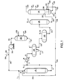
- a feed stream comprising vacuum gas oil and heavy coker gas oil is introduced into the process via line 1 and admixed with a hydrogen-rich recycle gas transported via line 35.
- the resulting admixture is carried via line 2 and admixed with a hereinafter-described recycle oil transported via line 24.
- This resulting admixture is then transported via line 3 into combination reaction zone 4 and is contacted with a denitrification and desulfurization catalyst.
- a resulting effluent from the denitrification and desulfurization catalyst is passed into a hydrocracking catalyst which is also contained in combination reaction zone 4.
- a resulting hydrocracked effluent from combination reaction zone 4 is carried via line 5 and is admixed with a water wash stream introduced via line 6 and the resulting admixture is transported via line 7 and introduced into heat-exchanger 8.
- a resulting cooled effluent from heat-exchanger 8 is transported via line 9 and introduced into vapor-liquid separator 10.
- a spent water wash stream is removed from vapor-liquid separator 10 via line 11.
- a hydrogen-rich gaseous stream containing hydrogen sulfide is removed from vapor-liquid separator 10 via line 27 and introduced into gas recovery zone 28.
- a lean solvent is introduced via line 29 into acid gas recovery zone 28 and contacts the hydrogen-rich gaseous stream in order to adsorb an acid gas.
- a rich solvent containing acid gas is removed from acid gas recovery zone 28 via line 30 and recovered.
- a hydrogen-rich gaseous stream containing a reduced concentration of acid gas is removed from acid gas recovery zone 28 via line 31, compressed in compressor 32.
- a compressed hydrogen-rich gaseous recycle stream is transported via line 33 and is admixed with a make-up hydrogen gaseous stream carried via line 34 and the resulting admixture is transported via line 35 and is admixed with the fresh feedstock as hereinabove described.
- a liquid hydrocarbonaceous stream is removed from vapor-liquid separator 10 via line 12 and is introduced into low pressure flash zone 13.
- a vaporous stream containing hydrogen and normally gaseous hydrocarbons is removed from low pressure flash zone 13 via line 14 and recovered.
- a liquid hydrocarbonaceous stream is removed from low pressure flash zone 13 via line 15 and introduced into stripper 16.
- a gaseous stream containing normally gaseous hydrocarbon compounds is removed from stripper 16 via line 17 and recovered.
- a liquid hydrocarbonaceous stream is removed from stripper 16 via line 18 and introduced into divided-wall fractionation zone 19.
- a naphtha boiling range hydrocarbon stream is removed from divided-wall fractionation zone 19 via line 20 and recovered.
- a kerosene boiling range hydrocarbonaceous stream is removed from divided-wall fractionation zone 19 via line 21 and recovered.
- a diesel boiling range hydrocarbonaceous stream is removed from divided-wall fractionation zone 19 via line 22 and recovered.
- a bottoms stream containing hydrocarbons boiling in the range of the fresh feedstock and containing heavy polynuclear aromatic compounds is removed from zone 37 located in the lower portion of divided-wall fractionation zone 19 via line 23. At least a portion of the hydrocarbonaceous stream carried via line 23 is transported via line 24 and recycled as hereinabove described. Another portion of the hydrocarbonaceous stream carried via line 23 is transported via line 25 and introduced into zone 38 located in the lower portion of divided-wall fractionation zone 19. Zone 38 of divided-wall fractionation zone 19 is stripped with steam which is introduced via line 36.
- a heavy hydrocarbonaceous stream containing an enhanced level of heavy polynuclear aromatic compounds is removed from zone 38 of divided-wall fractionation zone 19 via line 26 and recovered.
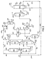
- a feed stream comprising vacuum gas oil and heavy coker gas oil is introduced into the process via line 51 and admixed with a hereinafter-described recycle stream provided via line 145 and the resulting admixture is transported via line 52 and is admixed with a hereinafter-described effluent from hydrocracking zone 127 transported via line 128.
- the resulting admixture is transported via line 53 into hydrotreating zone 54.
- the resulting effluent from hydrotreating zone 54 is transported via line 55 and introduced into stripping zone 56.
- a vaporous stream containing hydrocarbons and hydrogen passes upward in stripping zone 56 and is removed from stripping zone 56 via line 60 and introduced into aromatic saturation zone 111.
- a resulting effluent from aromatic saturation zone 111 is transported via line 112, admixed with a water wash stream introduced by line 113 and introduced into heat-exchanger 115 via line 114.
- a resulting cooled effluent from heat-exchanger 115 is transported via line 116 and introduced into vapor-liquid separator 117.
- a hydrogen-rich gaseous stream is removed from vapor-liquid separator 117 via line 118 and introduced into acid gas recovery zone 119.
- a lean solvent is introduced via line 120 into acid gas recovery zone 119 and contacts the hydrogen-rich gaseous stream in order to dissolve an acid gas.
- a rich solvent containing acid gas is removed from acid gas recovery zone 119 via line 121 and recovered.
- a hydrogen-rich gaseous stream containing a reduced concentration of acid gas is removed from acid gas recovery zone 119 via line 122, compressed in compresor 123, transported via line 124 and admixed with fresh make-up hydrogen which is introduced via line 149.
- the resulting admixture is transported via line 150 and at least a portion thereof is subsequently transported via lines 125 and 126 and is introduced into hydrocracking zone 127.
- Another portion of the hydrogen-rich gas is transported via line 151 and introduced into heat-exchanger 146.
- a resulting heated hydrogen-rich gaseous stream is removed from heat-exchanger 146 and is transported via line 152 and introduced into stripping zone 56.
- An aqueous stream containing dissolved salt compounds is removed from vapor-liquid separator 117 via line 131 and introduced into cold flash zone 132.
- a liquid hydrocarbonaceous stream is removed from vapor-liquid separator 117 via line 147 and is admixed with a gaseous stream provided via line 130 and the resulting admixture is transported via line 148 and introduced into cold flash zone 132.
- a gaseous stream is removed from cold flash zone 132 via line 133 and recovered.
- An aqueous stream containing dissolved salt compounds is removed from cold flash zone 132 via line 134 and recovered.
- a liquid hydrocarbonaceous stream is removed from cold flash zone 132 via line 135 and introduced into stripper 136.
- Stripping steam is provided via line 153 and introduced into stripper 136 to produce a stream containing normally gaseous hydrocarbons and transported via line 137.
- a liquid hydrocarbonaceous stream is removed from stripper 136 via line 138 and introduced into divided wall fractionator 139.
- a naphtha stream, a kerosene stream and a diesel stream are removed from divided wall fractionator 139 via lines 140, 141 and 142, respectively.
- a liquid hydrocarbonaceous stream containing compounds boiling in the range of the hydrocarbon feedstock is removed from divided wall fractionator 139 via line 145 and is transported and admixed with the fresh feedstock provided by line 51 as hereinabove described.
- a liquid hydrocarbonaceous stream containing compounds boiling in the range of the hydrocarbon feedstock is removed from stripping zone 56 via line 57 and a portion is transported via line 58 and line 126 and is introduced into hydrocracking zone 127 and another portion is transported via line 59 and introduced into hot flash zone 129.
- a vapor stream is removed from hot flash zone 129 via line 130 and is introduced into cold flash zone 132 via line 148.
- a liquid hydrocarbonaceous stream is removed from hot flash zone 129 via line 144 and transported and introduced into an isolated section of divided walled fractionator 139.
- a stream containing heavy polynuclear aromatic compounds is removed from divided wall fractionator 139 via line 143 and recovered.
- a hot hydrocracking catalyst zone effluent in an amount of 80,000 volume units of hydrocarbon and hydrogen is introduced into a hydrotreating catalyst zone operated at hydrotreating conditions including a pressure of 13 mPa, a hydrogen circulation rate of 1348 n m 3 /m 3 and a temperature of 399°C.
- the resulting effluent from the hydrotreating catalyst zone is passed to a hot, high-pressure stripper maintained at essentially the same temperature and pressure as the hydrotreating catalyst zone utilizing a hot, hydrogen-rich stripping gas to produce a vapor stream containing hydrogen and hydrocarbonaceous compounds boiling below and in the boiling range of the hydrocarbonaceous feedstock, and a liquid hydrocarbonaceous stream comprising hydrocarbonaceous compounds boiling in the range of the hydrocarbonaceous feedstock in an amount of 72,000 volume units which is introduced into the hydrocracking catalyst zone along with hydrogen in an amount of 2022 n m 3 /m 3 (based on feed to the hydrocracking catalyst zone) and a hereinafter-described liquid hydrocarbonaceous recycle stream in an amount of 8,000 volume units.
- the overhead vapor stream from the hot, high-pressure stripper is introduced into a post treat hydrogenation reactor at a temperature of 382°C to saturate at least a portion of the aromatic hydrocarbon compounds.
- the resulting effluent from the post treat hydrogenation reactor is cooled to a temperature of 54°C and introduced into a high pressure separator wherein a hydrogen-rich vapor stream is produced and subsequently, after acid gas scrubbing, is recycled, in part, to the hydrocracking catalyst zone.
- a liquid hydrocarbonaceous stream is removed from the high-pressure separator and introduced into a cold flash zone.
- a liquid hydrocarbonaceous stream in an amount of 1200 volume units and comprising hydrocarbonaceous compounds boiling in the range of the hydrocarbonaceous feedstock and heavy polynuclear aromatic compounds in an amount of 50 weight ppm is removed from the hot, high pressure stripper and introduced into a hot flash drum operated at a temperature of 399°C and a pressure of 1.7 mPa.
- a hot gaseous stream is removed from the hot flash drum, cooled and introduced into the previously described cold flash zone.
- a liquid hydrocarbonaceous stream is removed from the cold flash zone and introduced into a divided wall fractionation zone to produce products listed in Table 2.
- a liquid hydrocarbonaceous stream containing heavy polynuclear aromatic compounds is removed from the hot flash drum and introduced into the divided wall fractionation zone to recover vaporous hydrocarbons and a heavy liquid hydrocarbonaceous stream in an amount of 200 volume units and rich in heavy polynuclear aromatic compounds.
- Another liquid hydrocarbonaceous stream in an amount of 8,000 volume units and lean in heavy polynuclear aromatic compounds is removed from the divided wall fractionation zone and introduced into the hydrocracking zone as the liquid hydrocarbonaceous recycle stream described hereinabove.
- One hundred volume units of the hereinabove-described feedstock is admixed with 200 volume units of a hereinafter-described recycle stream and recycle hydrogen, and is introduced into a hydrotreating catalyst zone operated at hydrotreating conditions including a pressure of 6.8 mPa, a hydrogen circulation rate of 674 n m 3 /m 3 and a temperature of 399°C.
- the effluent from the hydrotreating catalyst zone is directly introduced into a hydrocracking catalyst zone operated at a temperature of 410°C.
- the resulting effluent from the hydrocracking catalyst zone is partially condensed and introduced into a high pressure vapor-liquid separator.
- a hydrogen-rich gaseous stream is removed from the high pressure vapor-liquid separator and at least a portion after acid gas scrubbing is recycled to the hydrotreating catalyst zone.
- a liquid hydrocarbonaceous stream is removed from the high pressure vapor-liquid separator and introduced into a low pressure vapor-liquid separator to produce a vapor stream containing hydrogen and normally gaseous hydrocarbons, and a liquid hydrocarbonaceous stream which is introduced into a stripper column.
- a stripped liquid hydrocarbonaceous stream is removed from the stripper column and introduced into a divided-wall fractionation zone to produce the products listed in Table 3.
- a heavy liquid hydrocarbonaceous stream containing hydrocarbon compounds boiling in the range of the hydrocarbonaceous feedstock and heavy polynuclear aromatic compounds in an amount of 50 weight ppm is removed from a first isolated section in the bottom of the divided-wall fractionation zone and 200 volume units are recycled and admixed with the fresh feedstock and 3 volume units are introduced into a second isolated section in the bottom of the divided-wall fractionation zone and stripped with steam.
- a heavy liquid hydrocarbonaceous stream in an amount of 0.5 volume units and rich in heavy polynuclear aromatic compounds is removed from the second isolated section in the bottom of the divided-wall fractionation zone and recovered.
Landscapes
- Chemical & Material Sciences (AREA)
- Oil, Petroleum & Natural Gas (AREA)
- Engineering & Computer Science (AREA)
- Chemical Kinetics & Catalysis (AREA)
- General Chemical & Material Sciences (AREA)
- Organic Chemistry (AREA)
- Production Of Liquid Hydrocarbon Mixture For Refining Petroleum (AREA)
- Catalysts (AREA)
Abstract
Description
At least a portion of the first liquid hydrocarbonaceous stream containing hydrocarbonaceous compounds boiling at a temperature greater than about 371°C recovered from the stripping zone is introduced into a hydrocracking zone along with added hydrogen.
| HYDROCRACKER FEEDSTOCK ANALYSIS | |
| 80% Vacuum Gas Oil/20% Coker Gas Oil from Arabian Crude | |
| Specific Gravity @ 16°C | 0.928 |
| Distillation, Volume Percent | |
| IBP, °C | 351 |
| 10 | 379 |
| 50 | 436 |
| 90 | 518 |
| EP | 565 |
| Sulfur, weight percent | 3.0 |
| Nitrogen, weight ppm | 1250 |
| Conradson Carbon, weight percent | 0.36 |
| Bromine Number | 7.5 |
| PRODUCT YIELDS | |
| Volume Units | |
| Butane | 1,150 |
| Light Naphtha | 3,100 |
| Heavy Naphtha | 3,000 |
| Turbine Fuel | 17,000 |
| Diesel Fuel | 20,000 |
| PRODUCT YIELDS | |
| Volume Units | |
| Butane | 3.2 |
| Light Naphtha | 7.8 |
| Heavy Naphtha | 9.4 |
| Turbine Fuel | 45.3 |
| Diesel Fuel | 48.2 |
Claims (10)
- A process for hydrocracking a hydrocarbonaceous feedstock which process comprises:(a) passing a hydrocarbonaceous input stream and hydrogen to a hydrocracking zone containing hydrocracking catalyst to produce a hydrocracking effluent;(b) combining a hydrocarbonaceous feedstock with at least one of the hydrocarboneous input streams or the hydrocracking effluent;(c) separating the effluent from said hydrocracking zone in a first separation zone to produce a first stream containing hydrogen and hydrocarbons boiling at a temperature below the boiling range of said hydrocarboneous input stream and a second stream comprising and heavy polynuclear aromatic compounds hydrocarbons boiling at a temperature in the boiling range of said hydrocarbonaceous input stream;(d) introducing at least a portion of the second stream into a second separation zone to produce a third stream comprising hydrocarbons boiling at a temperature in the boiling range of said hydrocarbonaceous input stream and heavy polynuclear aromatic compounds and a fourth stream comprising hydrocarbons boiling at a temperature equal to or below the boiling range of said hydrocarboneous input stream and having a lower concentration of heavy polynuclear aromatic compounds than the third stream;(e) introducing at least a portion of said third stream into a first divided zone located in the bottom end of a divided-wall fractionation zone to produce a fifth stream rich in polynuclear aromatic compounds;(f) recycling at least another portion of said second stream to said hydrocracking zone to provide at least a portion of said hydrocarbonaceous input stream; and(g) recovering a liquid hydrocarbonaceous product stream from at least a portion of at least one of the first stream or the fourth stream.
- The process of Claim 1 wherein prior to separation in the first separation zone the effluent from said hydrocracking zone and the hydrocarbonaceous feedstock pass to a denitrification and desulfurization reaction zone containing a catalyst and the denitrification and desulfurization reaction zone effluent undergoes separation to produce the first and second stream.
- The process of Claims 1 or 2 wherein the denitrification and desulfurization reaction zone effluent or the hydrocracking effluent passes directly to the first separation zone which comprises a hot, high pressure stripper utilizing a hot hydrogen-rich stripping gas to produce the first stream as a first vapor stream comprising hydrogen and hydrocarbonaceous compounds boiling at a temperature below the boiling range of said hydrocarbonaceous feedstock, and to produce the second stream comprising hydrocarbonaceous compounds boiling in the range of said hydrocarbonaceous feedstock.
- The process of Claim 3 wherein the effluent from the hydrocracking zone passes to the denitrification and desulfurization zone and at least a portion of said second stream passes to the hydrocracking zone as the hydrocarbonaceous input stream.
- The process of Claim 4 wherein the first stream passes to an aromatic saturation zone containing hydrogenation catalyst to produce a sixth stream comprising hydrocarbonaceous compounds boiling at a temperature below the boiling range of said hydrocarbonaceous feedstock and having a reduced concentration of aromatic compounds and at least a portion of the sixth stream and fourth stream pass to a second divided zone of the divided wall fractionation zone to recover at least a portion of said hydrocarbonaceous product stream.
- The process of Claim 5 wherein a liquid stream comprising hydrocarbonaceous compounds boiling in the range of said hydrocarbonaceous feedstock is recovered from said second divided zone and recycled to said denitrification and desulfurization reaction zone.
- The process of any of Claims 1-6 wherein said hydrocarbonaceous feedstock boils in the range from 232°C to 565°C.
- The process of any of Claims 3-7 wherein said hot, high pressure stripper is operated at a temperature no less than 38°C below the outlet temperature of said denitrification and desulfurization reaction zone and at a pressure no less than about 590 kPa below the outlet pressure of said denitrification and desulfurization reaction zone.
- The process of any of Claims 1-8 wherein said hydrocracking zone is operated at a conversion per pass in the range from 15% to 60%.
- The process of Claim 1 wherein the second separation zone comprises a second divided zone located in the bottom of the divided wall fractionation zone.
Applications Claiming Priority (2)
| Application Number | Priority Date | Filing Date | Title |
|---|---|---|---|
| US556805 | 2000-04-25 | ||
| US09/556,805 US6379535B1 (en) | 2000-04-25 | 2000-04-25 | Hydrocracking process |
Publications (3)
| Publication Number | Publication Date |
|---|---|
| EP1149886A2 true EP1149886A2 (en) | 2001-10-31 |
| EP1149886A3 EP1149886A3 (en) | 2003-05-02 |
| EP1149886B1 EP1149886B1 (en) | 2004-09-22 |
Family
ID=24222927
Family Applications (1)
| Application Number | Title | Priority Date | Filing Date |
|---|---|---|---|
| EP01109970A Expired - Lifetime EP1149886B1 (en) | 2000-04-25 | 2001-04-24 | Improved hydrocracking process |
Country Status (6)
| Country | Link |
|---|---|
| US (2) | US6379535B1 (en) |
| EP (1) | EP1149886B1 (en) |
| AT (1) | ATE277148T1 (en) |
| CA (1) | CA2344953C (en) |
| DE (1) | DE60105688T2 (en) |
| ES (1) | ES2225338T3 (en) |
Cited By (3)
| Publication number | Priority date | Publication date | Assignee | Title |
|---|---|---|---|---|
| EP1752511A1 (en) * | 2005-08-09 | 2007-02-14 | Uop Llc | A hydrocracking process for the production of ultra low sulfur diesel |
| WO2011006977A3 (en) * | 2009-07-15 | 2011-05-19 | Shell Internationale Research Maatschappij B.V. | Process for the conversion of a hydrocarbonaceous feedstock |
| WO2012170875A1 (en) * | 2011-06-09 | 2012-12-13 | Lyondell Chemical Technology, L.P. | Process comprising hydrocracking and hydrodesulfurisation step of a hydrocarbon feedstock followed by flash distillation |
Families Citing this family (52)
| Publication number | Priority date | Publication date | Assignee | Title |
|---|---|---|---|---|
| CN1114679C (en) * | 2000-05-19 | 2003-07-16 | 中国石油化工集团公司 | A medium pressure hydrocracking method |
| EP1720960A1 (en) * | 2004-01-16 | 2006-11-15 | Syntroleum Corporation | Process to produce synthetic fuels and lubricants |
| EP2038220A4 (en) | 2006-06-08 | 2010-08-11 | Chevron Usa Inc | SSZ-75 MOLECULAR SIEVE COMPOSITION OF MATERIAL AND SYNTHESIS THEREOF |
| US7906698B2 (en) * | 2006-06-08 | 2011-03-15 | Chevron U.S.A. Inc. | Hydrocarbon conversion using molecular sieve SSZ-75 |
| US7622034B1 (en) | 2006-12-29 | 2009-11-24 | Uop Llc | Hydrocarbon conversion process |
| US8764970B1 (en) | 2008-09-10 | 2014-07-01 | Marathon Petroleum Company Lp | Hydroprocessing |
| EP2507345A1 (en) * | 2009-12-01 | 2012-10-10 | ExxonMobil Research and Engineering Company | Two stage hydroprocessing with divided wall column fractionator |
| US8262901B2 (en) * | 2009-12-18 | 2012-09-11 | Uop Llc | Adsorbing polynuclear aromatics from a reforming process using adsorbents containing iron |
| US8518240B2 (en) * | 2009-12-18 | 2013-08-27 | Uop Llc | Adsorbing polynuclear aromatics from a reforming process at reaction temperatures |
| US8894839B2 (en) * | 2010-02-22 | 2014-11-25 | Uop Llc | Process, system, and apparatus for a hydrocracking zone |
| US8691082B2 (en) | 2010-09-30 | 2014-04-08 | Uop Llc | Two-stage hydroprocessing with common fractionation |
| US8608947B2 (en) | 2010-09-30 | 2013-12-17 | Uop Llc | Two-stage hydrotreating process |
| US8911694B2 (en) | 2010-09-30 | 2014-12-16 | Uop Llc | Two-stage hydroprocessing apparatus with common fractionation |
| WO2012052042A1 (en) | 2010-10-20 | 2012-04-26 | Haldor Topsøe A/S | Process for hydrocracking a hydrocarbon feedstock |
| EP2930225B1 (en) | 2010-10-20 | 2023-08-16 | Topsoe A/S | Process for hydrocracking a hydrocarbon feedstock |
| BR112013008603A2 (en) | 2010-10-20 | 2017-07-25 | Haldor Topsoe As | process for hydrocracking a hydrocarbon feedstock |
| US8852404B2 (en) * | 2010-12-14 | 2014-10-07 | Uop Llc | Apparatus for removing heavy polynuclear aromatic compounds from a hydroprocessed stream |
| WO2012082394A2 (en) * | 2010-12-14 | 2012-06-21 | Uop Llc | Process and apparatus for removing heavy polynuclear aromatic compounds from a hydroprocessed stream |
| US8574425B2 (en) | 2010-12-14 | 2013-11-05 | Uop Llc | Process for removing heavy polynuclear aromatic compounds from a hydroprocessed stream |
| WO2012163850A1 (en) | 2011-05-27 | 2012-12-06 | Shell Internationale Research Maatschappij B.V. | Multi-stage hydrocracking process for the hydroconversion of hydrocarbonaceous feedstocks |
| CN103421541A (en) * | 2012-05-15 | 2013-12-04 | 中国石油天然气股份有限公司 | A kind of hydrocracking process |
| US9181501B2 (en) * | 2012-08-17 | 2015-11-10 | Uop Llc | Method and apparatus for removing H2S and moisture from fractionator overhead naphtha |
| US8877040B2 (en) | 2012-08-20 | 2014-11-04 | Uop Llc | Hydrotreating process and apparatus relating thereto |
| US8877014B2 (en) * | 2012-12-14 | 2014-11-04 | Uop Llc | Split-shell fractionation columns and associated processes for separating aromatic hydrocarbons |
| US20140179975A1 (en) * | 2012-12-26 | 2014-06-26 | Uop Llc | Split-shell raffinate columns and methods for use in continuous adsorptive separation processes |
| WO2014152341A1 (en) | 2013-03-15 | 2014-09-25 | Saudi Arabian Oil Company | Two stage hydrocracking process and apparatus for multiple grade lube oil base feedstock production |
| US9359564B2 (en) * | 2013-08-30 | 2016-06-07 | Uop Llc | Process and apparatus for producing diesel with high cetane |
| US10307739B2 (en) * | 2013-12-11 | 2019-06-04 | Idemitsu Kosan Co., Ltd. | Catalyst for hydrocracking and hydrocarbon production method |
| FR3030566B1 (en) * | 2014-12-22 | 2018-07-27 | Axens | METHOD AND DEVICE FOR REDUCING HEAVY POLYCYCLIC AROMATIC COMPOUNDS IN HYDROCRACKING UNITS |
| US10011786B1 (en) | 2017-02-28 | 2018-07-03 | Uop Llc | Hydrocracking process and apparatus with HPNA removal |
| US10435635B2 (en) * | 2017-03-31 | 2019-10-08 | Uop Llc | Hydrocracking process and apparatus with heavy polynuclear aromatics removal from a reboiled column |
| US10696906B2 (en) | 2017-09-29 | 2020-06-30 | Marathon Petroleum Company Lp | Tower bottoms coke catching device |
| CN108641749B (en) * | 2018-05-11 | 2023-04-18 | 内蒙古晟源科技有限公司 | Hydrogenation combination process method for producing high-quality fuel through medium-low temperature coal tar |
| US12000720B2 (en) | 2018-09-10 | 2024-06-04 | Marathon Petroleum Company Lp | Product inventory monitoring |
| US12031676B2 (en) | 2019-03-25 | 2024-07-09 | Marathon Petroleum Company Lp | Insulation securement system and associated methods |
| US11975316B2 (en) | 2019-05-09 | 2024-05-07 | Marathon Petroleum Company Lp | Methods and reforming systems for re-dispersing platinum on reforming catalyst |
| CA3212048A1 (en) | 2019-05-30 | 2020-11-30 | Marathon Petroleum Company Lp | Methods and systems for minimizing nox and co emissions in natural draft heaters |
| US11136512B2 (en) | 2019-12-05 | 2021-10-05 | Saudi Arabian Oil Company | Two-stage hydrocracking unit with intermediate HPNA hydrogenation step |
| CA3109606C (en) | 2020-02-19 | 2022-12-06 | Marathon Petroleum Company Lp | Low sulfur fuel oil blends for paraffinic resid stability and associated methods |
| US12461022B2 (en) | 2021-02-25 | 2025-11-04 | Marathon Petroleum Company Lp | Methods and assemblies for determining and using standardized spectral responses for calibration of spectroscopic analyzers |
| US11905468B2 (en) | 2021-02-25 | 2024-02-20 | Marathon Petroleum Company Lp | Assemblies and methods for enhancing control of fluid catalytic cracking (FCC) processes using spectroscopic analyzers |
| US11702600B2 (en) | 2021-02-25 | 2023-07-18 | Marathon Petroleum Company Lp | Assemblies and methods for enhancing fluid catalytic cracking (FCC) processes during the FCC process using spectroscopic analyzers |
| US20250012744A1 (en) | 2021-02-25 | 2025-01-09 | Marathon Petroleum Company Lp | Methods and assemblies for enhancing control of refining processes using spectroscopic analyzers |
| US12473500B2 (en) | 2021-02-25 | 2025-11-18 | Marathon Petroleum Company Lp | Assemblies and methods for enhancing control of fluid catalytic cracking (FCC) processes using spectroscopic analyzers |
| US11898109B2 (en) | 2021-02-25 | 2024-02-13 | Marathon Petroleum Company Lp | Assemblies and methods for enhancing control of hydrotreating and fluid catalytic cracking (FCC) processes using spectroscopic analyzers |
| US11692141B2 (en) | 2021-10-10 | 2023-07-04 | Marathon Petroleum Company Lp | Methods and systems for enhancing processing of hydrocarbons in a fluid catalytic cracking unit using a renewable additive |
| US11802257B2 (en) | 2022-01-31 | 2023-10-31 | Marathon Petroleum Company Lp | Systems and methods for reducing rendered fats pour point |
| US12311305B2 (en) | 2022-12-08 | 2025-05-27 | Marathon Petroleum Company Lp | Removable flue gas strainer and associated methods |
| CA3238046A1 (en) | 2023-05-12 | 2025-07-07 | Marathon Petroleum Company Lp | Systems, apparatuses, and methods for sample cylinder inspection, pressurization, and sample disposal |
| US12533615B2 (en) | 2023-06-02 | 2026-01-27 | Marathon Petroleum Company Lp | Methods and systems for reducing contaminants in a feed stream |
| US12415962B2 (en) | 2023-11-10 | 2025-09-16 | Marathon Petroleum Company Lp | Systems and methods for producing aviation fuel |
| US12599848B2 (en) | 2024-06-03 | 2026-04-14 | Marathon Petroleum Company Lp | Systems, analyzers, controllers, and associated methods to enhance fluid separation for distillation operations |
Family Cites Families (7)
| Publication number | Priority date | Publication date | Assignee | Title |
|---|---|---|---|---|
| US3328290A (en) | 1965-03-30 | 1967-06-27 | Standard Oil Co | Two-stage process for the hydrocracking of hydrocarbon oils in which the feed oil ispretreated in the first stage |
| US3437584A (en) * | 1967-08-09 | 1969-04-08 | Universal Oil Prod Co | Method for converting heavy carbonaceous materials |
| US3779897A (en) * | 1971-12-29 | 1973-12-18 | Texaco Inc | Hydrotreating-hydrocracking process for manufacturing gasoline range hydrocarbons |
| US5120427A (en) | 1988-05-23 | 1992-06-09 | Uop | High conversion high vaporization hydrocracking process |
| US5114562A (en) | 1990-08-03 | 1992-05-19 | Uop | Two-stage hydrodesulfurization and hydrogenation process for distillate hydrocarbons |
| WO1997038066A1 (en) | 1996-04-09 | 1997-10-16 | Chevron U.S.A. Inc. | Process for reverse staging in hydroprocessing reactor systems |
| US5720872A (en) | 1996-12-31 | 1998-02-24 | Exxon Research And Engineering Company | Multi-stage hydroprocessing with multi-stage stripping in a single stripper vessel |
-
2000
- 2000-04-25 US US09/556,805 patent/US6379535B1/en not_active Expired - Lifetime
-
2001
- 2001-04-24 DE DE60105688T patent/DE60105688T2/en not_active Expired - Lifetime
- 2001-04-24 EP EP01109970A patent/EP1149886B1/en not_active Expired - Lifetime
- 2001-04-24 AT AT01109970T patent/ATE277148T1/en active
- 2001-04-24 ES ES01109970T patent/ES2225338T3/en not_active Expired - Lifetime
- 2001-04-25 CA CA2344953A patent/CA2344953C/en not_active Expired - Lifetime
-
2002
- 2002-01-22 US US10/054,754 patent/US6858128B1/en not_active Expired - Fee Related
Cited By (5)
| Publication number | Priority date | Publication date | Assignee | Title |
|---|---|---|---|---|
| EP1752511A1 (en) * | 2005-08-09 | 2007-02-14 | Uop Llc | A hydrocracking process for the production of ultra low sulfur diesel |
| WO2011006977A3 (en) * | 2009-07-15 | 2011-05-19 | Shell Internationale Research Maatschappij B.V. | Process for the conversion of a hydrocarbonaceous feedstock |
| CN102471701A (en) * | 2009-07-15 | 2012-05-23 | 国际壳牌研究有限公司 | Process for the conversion of a hydrocarbonaceous feedstock |
| RU2543719C2 (en) * | 2009-07-15 | 2015-03-10 | Шелл Интернэшнл Рисерч Маатсхаппий Б.В. | Hydrocarbon stock conversion procedure |
| WO2012170875A1 (en) * | 2011-06-09 | 2012-12-13 | Lyondell Chemical Technology, L.P. | Process comprising hydrocracking and hydrodesulfurisation step of a hydrocarbon feedstock followed by flash distillation |
Also Published As
| Publication number | Publication date |
|---|---|
| CA2344953C (en) | 2010-06-22 |
| DE60105688D1 (en) | 2004-10-28 |
| ES2225338T3 (en) | 2005-03-16 |
| CA2344953A1 (en) | 2001-10-25 |
| DE60105688T2 (en) | 2005-10-06 |
| US6858128B1 (en) | 2005-02-22 |
| EP1149886A3 (en) | 2003-05-02 |
| EP1149886B1 (en) | 2004-09-22 |
| ATE277148T1 (en) | 2004-10-15 |
| US6379535B1 (en) | 2002-04-30 |
Similar Documents
| Publication | Publication Date | Title |
|---|---|---|
| EP1149886B1 (en) | Improved hydrocracking process | |
| US6379532B1 (en) | Hydrocracking process | |
| US6296758B1 (en) | Hydrocracking process | |
| US6190535B1 (en) | Hydrocracking process | |
| US7591940B2 (en) | Combination hydrocracking process for the production of ultra low sulfur diesel | |
| US6596155B1 (en) | Hydrocracking process | |
| US6623623B2 (en) | Simultaneous hydroprocessing of two feedstocks | |
| EP1103592B1 (en) | Improved hydrocracking process | |
| US7005057B1 (en) | Hydrocracking process for the production of ultra low sulfur diesel | |
| US6106694A (en) | Hydrocracking process | |
| US6638418B1 (en) | Dual recycle hydrocracking process | |
| US6379533B1 (en) | Hydrocracking process for production of LPG and distillate hydrocarbons | |
| US7470358B1 (en) | Integrated process for the production of low sulfur diesel | |
| US7108779B1 (en) | Hydrocarbon desulfurization process | |
| US6361683B1 (en) | Hydrocracking process | |
| EP1270705B1 (en) | Simultaneous hydroprocessing of two feedstocks | |
| US7041211B2 (en) | Hydrocracking process | |
| US6387245B1 (en) | Hydrocracking process | |
| US7419582B1 (en) | Process for hydrocracking a hydrocarbon feedstock | |
| EP1326948A1 (en) | Hydrocracking process | |
| US7842180B1 (en) | Hydrocracking process | |
| CA2491012C (en) | An improved hydrocracking process | |
| EP1752511B1 (en) | A hydrocracking process for the production of ultra low sulfur diesel | |
| WO2012082394A2 (en) | Process and apparatus for removing heavy polynuclear aromatic compounds from a hydroprocessed stream | |
| AU5394101A (en) | Simultaneous hydroprocessing of two feedstocks |
Legal Events
| Date | Code | Title | Description |
|---|---|---|---|
| PUAI | Public reference made under article 153(3) epc to a published international application that has entered the european phase |
Free format text: ORIGINAL CODE: 0009012 |
|
| AK | Designated contracting states |
Kind code of ref document: A2 Designated state(s): AT BE CH CY DE DK ES FI FR GB GR IE IT LI LU MC NL PT SE TR |
|
| AX | Request for extension of the european patent |
Free format text: AL;LT;LV;MK;RO;SI |
|
| PUAL | Search report despatched |
Free format text: ORIGINAL CODE: 0009013 |
|
| AK | Designated contracting states |
Designated state(s): AT BE CH CY DE DK ES FI FR GB GR IE IT LI LU MC NL PT SE TR |
|
| AX | Request for extension of the european patent |
Extension state: AL LT LV MK RO SI |
|
| 17P | Request for examination filed |
Effective date: 20030709 |
|
| 17Q | First examination report despatched |
Effective date: 20031006 |
|
| AKX | Designation fees paid |
Designated state(s): AT BE CH CY DE DK ES FI FR GB GR IE IT LI LU MC NL PT SE TR |
|
| GRAP | Despatch of communication of intention to grant a patent |
Free format text: ORIGINAL CODE: EPIDOSNIGR1 |
|
| GRAS | Grant fee paid |
Free format text: ORIGINAL CODE: EPIDOSNIGR3 |
|
| GRAA | (expected) grant |
Free format text: ORIGINAL CODE: 0009210 |
|
| AK | Designated contracting states |
Kind code of ref document: B1 Designated state(s): AT BE CH CY DE DK ES FI FR GB GR IE IT LI LU MC NL PT SE TR |
|
| PG25 | Lapsed in a contracting state [announced via postgrant information from national office to epo] |
Ref country code: CH Free format text: LAPSE BECAUSE OF FAILURE TO SUBMIT A TRANSLATION OF THE DESCRIPTION OR TO PAY THE FEE WITHIN THE PRESCRIBED TIME-LIMIT Effective date: 20040922 Ref country code: LI Free format text: LAPSE BECAUSE OF FAILURE TO SUBMIT A TRANSLATION OF THE DESCRIPTION OR TO PAY THE FEE WITHIN THE PRESCRIBED TIME-LIMIT Effective date: 20040922 Ref country code: TR Free format text: LAPSE BECAUSE OF FAILURE TO SUBMIT A TRANSLATION OF THE DESCRIPTION OR TO PAY THE FEE WITHIN THE PRESCRIBED TIME-LIMIT Effective date: 20040922 |
|
| REG | Reference to a national code |
Ref country code: GB Ref legal event code: FG4D |
|
| REG | Reference to a national code |
Ref country code: CH Ref legal event code: EP |
|
| REG | Reference to a national code |
Ref country code: IE Ref legal event code: FG4D |
|
| REF | Corresponds to: |
Ref document number: 60105688 Country of ref document: DE Date of ref document: 20041028 Kind code of ref document: P |
|
| REG | Reference to a national code |
Ref country code: SE Ref legal event code: TRGR |
|
| PG25 | Lapsed in a contracting state [announced via postgrant information from national office to epo] |
Ref country code: DK Free format text: LAPSE BECAUSE OF FAILURE TO SUBMIT A TRANSLATION OF THE DESCRIPTION OR TO PAY THE FEE WITHIN THE PRESCRIBED TIME-LIMIT Effective date: 20041222 Ref country code: GR Free format text: LAPSE BECAUSE OF FAILURE TO SUBMIT A TRANSLATION OF THE DESCRIPTION OR TO PAY THE FEE WITHIN THE PRESCRIBED TIME-LIMIT Effective date: 20041222 |
|
| REG | Reference to a national code |
Ref country code: ES Ref legal event code: FG2A Ref document number: 2225338 Country of ref document: ES Kind code of ref document: T3 |
|
| REG | Reference to a national code |
Ref country code: CH Ref legal event code: PL |
|
| PG25 | Lapsed in a contracting state [announced via postgrant information from national office to epo] |
Ref country code: CY Free format text: LAPSE BECAUSE OF FAILURE TO SUBMIT A TRANSLATION OF THE DESCRIPTION OR TO PAY THE FEE WITHIN THE PRESCRIBED TIME-LIMIT Effective date: 20050424 Ref country code: LU Free format text: LAPSE BECAUSE OF NON-PAYMENT OF DUE FEES Effective date: 20050424 |
|
| PG25 | Lapsed in a contracting state [announced via postgrant information from national office to epo] |
Ref country code: IE Free format text: LAPSE BECAUSE OF NON-PAYMENT OF DUE FEES Effective date: 20050425 |
|
| PG25 | Lapsed in a contracting state [announced via postgrant information from national office to epo] |
Ref country code: MC Free format text: LAPSE BECAUSE OF NON-PAYMENT OF DUE FEES Effective date: 20050430 |
|
| ET | Fr: translation filed | ||
| PLBE | No opposition filed within time limit |
Free format text: ORIGINAL CODE: 0009261 |
|
| STAA | Information on the status of an ep patent application or granted ep patent |
Free format text: STATUS: NO OPPOSITION FILED WITHIN TIME LIMIT |
|
| 26N | No opposition filed |
Effective date: 20050623 |
|
| PG25 | Lapsed in a contracting state [announced via postgrant information from national office to epo] |
Ref country code: PT Free format text: LAPSE BECAUSE OF NON-PAYMENT OF DUE FEES Effective date: 20050222 |
|
| PGFP | Annual fee paid to national office [announced via postgrant information from national office to epo] |
Ref country code: DE Payment date: 20120430 Year of fee payment: 12 |
|
| PGFP | Annual fee paid to national office [announced via postgrant information from national office to epo] |
Ref country code: FI Payment date: 20120404 Year of fee payment: 12 Ref country code: SE Payment date: 20120410 Year of fee payment: 12 Ref country code: BE Payment date: 20120516 Year of fee payment: 12 |
|
| PGFP | Annual fee paid to national office [announced via postgrant information from national office to epo] |
Ref country code: AT Payment date: 20120327 Year of fee payment: 12 |
|
| BERE | Be: lapsed |
Owner name: *UOP LLC Effective date: 20130430 |
|
| REG | Reference to a national code |
Ref country code: SE Ref legal event code: EUG |
|
| REG | Reference to a national code |
Ref country code: AT Ref legal event code: MM01 Ref document number: 277148 Country of ref document: AT Kind code of ref document: T Effective date: 20130430 |
|
| PG25 | Lapsed in a contracting state [announced via postgrant information from national office to epo] |
Ref country code: SE Free format text: LAPSE BECAUSE OF NON-PAYMENT OF DUE FEES Effective date: 20130425 Ref country code: DE Free format text: LAPSE BECAUSE OF NON-PAYMENT OF DUE FEES Effective date: 20131101 Ref country code: BE Free format text: LAPSE BECAUSE OF NON-PAYMENT OF DUE FEES Effective date: 20130430 Ref country code: AT Free format text: LAPSE BECAUSE OF NON-PAYMENT OF DUE FEES Effective date: 20130430 |
|
| REG | Reference to a national code |
Ref country code: DE Ref legal event code: R119 Ref document number: 60105688 Country of ref document: DE Effective date: 20131101 |
|
| PG25 | Lapsed in a contracting state [announced via postgrant information from national office to epo] |
Ref country code: FI Free format text: LAPSE BECAUSE OF NON-PAYMENT OF DUE FEES Effective date: 20130424 |
|
| REG | Reference to a national code |
Ref country code: FR Ref legal event code: PLFP Year of fee payment: 16 |
|
| PGFP | Annual fee paid to national office [announced via postgrant information from national office to epo] |
Ref country code: GB Payment date: 20160329 Year of fee payment: 16 Ref country code: FR Payment date: 20160331 Year of fee payment: 16 |
|
| PGFP | Annual fee paid to national office [announced via postgrant information from national office to epo] |
Ref country code: NL Payment date: 20160404 Year of fee payment: 16 |
|
| PGFP | Annual fee paid to national office [announced via postgrant information from national office to epo] |
Ref country code: ES Payment date: 20160404 Year of fee payment: 16 |
|
| PGFP | Annual fee paid to national office [announced via postgrant information from national office to epo] |
Ref country code: IT Payment date: 20160414 Year of fee payment: 16 |
|
| REG | Reference to a national code |
Ref country code: NL Ref legal event code: MM Effective date: 20170501 |
|
| GBPC | Gb: european patent ceased through non-payment of renewal fee |
Effective date: 20170424 |
|
| REG | Reference to a national code |
Ref country code: FR Ref legal event code: ST Effective date: 20171229 |
|
| PG25 | Lapsed in a contracting state [announced via postgrant information from national office to epo] |
Ref country code: NL Free format text: LAPSE BECAUSE OF NON-PAYMENT OF DUE FEES Effective date: 20170501 Ref country code: FR Free format text: LAPSE BECAUSE OF NON-PAYMENT OF DUE FEES Effective date: 20170502 |
|
| PG25 | Lapsed in a contracting state [announced via postgrant information from national office to epo] |
Ref country code: GB Free format text: LAPSE BECAUSE OF NON-PAYMENT OF DUE FEES Effective date: 20170424 |
|
| PG25 | Lapsed in a contracting state [announced via postgrant information from national office to epo] |
Ref country code: IT Free format text: LAPSE BECAUSE OF NON-PAYMENT OF DUE FEES Effective date: 20170424 |
|
| REG | Reference to a national code |
Ref country code: ES Ref legal event code: FD2A Effective date: 20180703 |
|
| PG25 | Lapsed in a contracting state [announced via postgrant information from national office to epo] |
Ref country code: ES Free format text: LAPSE BECAUSE OF NON-PAYMENT OF DUE FEES Effective date: 20170425 |