EP1103592B1 - Improved hydrocracking process - Google Patents
Improved hydrocracking process Download PDFInfo
- Publication number
- EP1103592B1 EP1103592B1 EP00125533A EP00125533A EP1103592B1 EP 1103592 B1 EP1103592 B1 EP 1103592B1 EP 00125533 A EP00125533 A EP 00125533A EP 00125533 A EP00125533 A EP 00125533A EP 1103592 B1 EP1103592 B1 EP 1103592B1
- Authority
- EP
- European Patent Office
- Prior art keywords
- hydrogen
- stream
- zone
- hydrocracking
- hydrocarbonaceous
- Prior art date
- Legal status (The legal status is an assumption and is not a legal conclusion. Google has not performed a legal analysis and makes no representation as to the accuracy of the status listed.)
- Expired - Lifetime
Links
Images
Classifications
-
- C—CHEMISTRY; METALLURGY
- C10—PETROLEUM, GAS OR COKE INDUSTRIES; TECHNICAL GASES CONTAINING CARBON MONOXIDE; FUELS; LUBRICANTS; PEAT
- C10G—CRACKING HYDROCARBON OILS; PRODUCTION OF LIQUID HYDROCARBON MIXTURES, e.g. BY DESTRUCTIVE HYDROGENATION, OLIGOMERISATION, POLYMERISATION; RECOVERY OF HYDROCARBON OILS FROM OIL-SHALE, OIL-SAND, OR GASES; REFINING MIXTURES MAINLY CONSISTING OF HYDROCARBONS; REFORMING OF NAPHTHA; MINERAL WAXES
- C10G69/00—Treatment of hydrocarbon oils by at least one hydrotreatment process and at least one other conversion process
- C10G69/02—Treatment of hydrocarbon oils by at least one hydrotreatment process and at least one other conversion process plural serial stages only
- C10G69/04—Treatment of hydrocarbon oils by at least one hydrotreatment process and at least one other conversion process plural serial stages only including at least one step of catalytic cracking in the absence of hydrogen
-
- C—CHEMISTRY; METALLURGY
- C10—PETROLEUM, GAS OR COKE INDUSTRIES; TECHNICAL GASES CONTAINING CARBON MONOXIDE; FUELS; LUBRICANTS; PEAT
- C10G—CRACKING HYDROCARBON OILS; PRODUCTION OF LIQUID HYDROCARBON MIXTURES, e.g. BY DESTRUCTIVE HYDROGENATION, OLIGOMERISATION, POLYMERISATION; RECOVERY OF HYDROCARBON OILS FROM OIL-SHALE, OIL-SAND, OR GASES; REFINING MIXTURES MAINLY CONSISTING OF HYDROCARBONS; REFORMING OF NAPHTHA; MINERAL WAXES
- C10G65/00—Treatment of hydrocarbon oils by two or more hydrotreatment processes only
- C10G65/02—Treatment of hydrocarbon oils by two or more hydrotreatment processes only plural serial stages only
- C10G65/12—Treatment of hydrocarbon oils by two or more hydrotreatment processes only plural serial stages only including cracking steps and other hydrotreatment steps
-
- C—CHEMISTRY; METALLURGY
- C10—PETROLEUM, GAS OR COKE INDUSTRIES; TECHNICAL GASES CONTAINING CARBON MONOXIDE; FUELS; LUBRICANTS; PEAT
- C10G—CRACKING HYDROCARBON OILS; PRODUCTION OF LIQUID HYDROCARBON MIXTURES, e.g. BY DESTRUCTIVE HYDROGENATION, OLIGOMERISATION, POLYMERISATION; RECOVERY OF HYDROCARBON OILS FROM OIL-SHALE, OIL-SAND, OR GASES; REFINING MIXTURES MAINLY CONSISTING OF HYDROCARBONS; REFORMING OF NAPHTHA; MINERAL WAXES
- C10G49/00—Treatment of hydrocarbon oils, in the presence of hydrogen or hydrogen-generating compounds, not provided for in a single one of groups C10G45/02, C10G45/32, C10G45/44, C10G45/58 or C10G47/00
- C10G49/22—Separation of effluents
Definitions
- the field of art to which this invention pertains is the hydrocracking of a hydrocarbonaceous feedstock.
- Petroleum refiners often produce desirable products such as turbine fuel, diesel fuel and other products known as middle distillates as well as lower boiling hydrocarbonaceous liquids such as naphtha and gasoline by hydrocracking a hydrocarbon feedstock derived from crude oil, for example.
- Feedstocks most often subjected to hydrocracking are gas oils and heavy gas oils recovered from crude oil by distillation.
- a typical heavy gas oil comprises a substantial portion of hydrocarbon components boiling above 371°C, usually at least 50 percent by weight boiling above 371°C.
- a typical vacuum gas oil normally has a boiling point range between 315°C and 566°C.
- Hydrocracking is generally accomplished by contacting in a hydrocracking reaction vessel or zone the gas oil or other feedstock to be treated with a suitable hydrocracking catalyst under conditions of elevated temperature and pressure in the presence of hydrogen so as to yield a product containing a distribution of hydrocarbon products desired by the refiner.
- a hydrocracking reaction vessel or zone the gas oil or other feedstock to be treated with a suitable hydrocracking catalyst under conditions of elevated temperature and pressure in the presence of hydrogen so as to yield a product containing a distribution of hydrocarbon products desired by the refiner.
- the operating conditions and the hydrocracking catalysts within a hydrocracking reactor influence the yield of the hydrocracked products.
- US-A-5,720,872 discloses a process for hydroprocessing liquid feedstocks in two or more hydroprocessing stages which are in separate reaction vessels and wherein each reaction stage contains a bed of hydroprocessing catalyst.
- the liquid product from the first reaction stage is sent to a low pressure stripping stage and stripped of hydrogen sulfide, ammonia and other dissolved gases.
- the stripped product stream is then sent to the next downstream reaction stage, the product from which is also stripped of dissolved gases and sent to the next downstream reaction stage until the last reaction stage, the liquid product of which is stripped of dissolved gases and collected or passed on for further processing.
- the flow of treat gas is in a direction opposite the direction in which the reaction stages are staged for the flow of liquid.
- Each stripping stage is a separate stage, but all stages are contained in the same stripper vessel.
- US-A-3,328,290 discloses a two-stage process for the hydrocracking of hydrocarbons in which the feed is pretreated in the first stage.
- US-A-5,114,562 discloses a process wherein a middle distillate petroleum stream is hydrotreated to produce a low sulfur and low aromatic product employing two reaction zones in series.
- the effluent of the first reaction zone is cooled and purged of hydrogen sulfide by stripping and then reheated by indirect heat exchange.
- the second reaction zone employs a sulfur-sensitive noble metal hydrogenation catalyst. Operating pressure and space velocity increase, and operating temperature decreases from the first to the second reaction zones.
- the '562 patent teaches that the hydroprocessing reactions of the hydrodenitrification and hydrodesulfurization will occur with very limited hydrocracking of the feedstock. Also, it is totally undesired to perform any significant cracking within the second reaction zone.
- US-A-5980729 discloses a process for hydrocracking a hydrocarbonaceous feedstock which process comprises a hydrocracking zone followed by a denitrification and desulfurization reaction zone.
- the effluent from the denitrification and desulfurization reaction zone is stripped in a hot stripper.
- the hydrocarbonaceous liquid stream from the hot stripper is fed to the hydrocracking zone.
- the vapor stream comprising hydrogen, hydrocarbonaceous compounds, hydrogen sulfide and ammonia from the hot stripper is passed into an aromatic saturation zone to reduce the concentration of aromatic compounds and the resulting effluent from said aromatic saturation zone is cooled to produce a hydrogen-rich gaseous stream recycled to the hydrocracking zone and a hydrocracked hydrocarbonaceous product stream.
- US-A-3592757 discloses a process for hydrocracking a hydrocarbonaceous feedstock which process comprises a denitrification and desulfurization reaction zone, a hydrocracking zone, a separation of a vapor phase, a distillation of the resulting liquid stream, hydrosaturation of the aromatics of a stream taken from the distillation column for the production of jet fuel and gasoline.
- the present invention is a catalytic hydrocracking process which provides higher liquid product yields, specifically higher yields of turbine fuel and diesel oil.
- the process of the present invention provides the yield advantages associated with a low conversion per pass operation without compromising unit economics.
- Other benefits of a low conversion per pass operation include the minimization of the need for inter-bed hydrogen quench and the minimization of the fresh feed pre-heat since the higher flow rate of recycle liquid will provide additional process heat to initiate the catalytic reaction and an additional heat sink to absorb the heat of reaction. An overall reduction in fuel gas and hydrogen consumption, and light ends production may also be obtained.
- the low conversion per pass operation requires less catalyst volume.
- the present invention relates to a process for hydrocracking a hydrocarbonaceous feedstock which process comprises: (a) passing a hydrocarbonaceous feedstock, a liquid recycle stream and hydrogen to a denitrification and desulfurization reaction zone containing a catalyst and recovering a denitrification and desulfurization reaction zone effluent therefrom; (b) passing the denitrification and desulfurization reaction zone effluent to a hydrocracking zone containing hydrocracking catalyst; (c) passing a resulting effluent from the hydrocracking zone directly to a hot, high pressure stripper utilizing a hot, hydrogen-rich stripping gas to produce a first vapor stream comprising hydrogen, hydrocarbonaceous compounds boiling at a temperature below the boiling range of the hydrocarbonaceous feedstock, hydrogen sulfide and ammonia, and a first liquid stream comprising hydrocarbonaceous compounds boiling in the range of the hydrocarbonaceous feedstock; (d) passing at least a portion of the first liquid stream comprising hydro
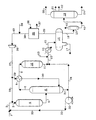
- the drawing is a simplified process flow diagram of a preferred embodiment of the present invention.
- the drawing is intended to be schematically illustrative of the present invention and not be a limitation thereof.
- the process of the present invention is particularly useful for hydrocracking a hydrocarbonaceous oil containing hydrocarbons and/or other organic materials to produce a product containing hydrocarbons and/or other organic materials of lower average boiling point and lower average molecular weight.
- the hydrocarbonaceous feedstocks that may be subjected to hydrocracking by the method of the invention include all mineral oils and synthetic oils (e.g., shale oil, tar sand products, etc.) and fractions thereof.
- Illustrative hydrocarbonaceous feedstocks include those containing components boiling above 288°C, such as atmospheric gas oils, vacuum gas oils, deasphalted, vacuum, and atmospheric residua, hydrotreated or mildly hydrocracked residual oils, coker distillates, straight run distillates, solvent-deasphalted oils, pyrolysis-derived oils, high boiling synthetic oils, cycle oils and cat cracker distilllates.
- a preferred hydrocracking feedstock is a gas oil or other hydrocarbon fraction having at least 50% by weight, and most usually at least 75% by weight, of its components boiling at temperatures above the end point of the desired product, which end point, in the case of heavy gasoline, is generally in the range from 193°C to 215°C.
- One of the most preferred gas oil feedstocks will contain hydrocarbon components which boil above 288°C with best results being achieved with feeds containing at least 25 percent by volume of the components boiling between 315°C and 538°C.
- petroleum distillates wherein at least 90 percent of the components boil in the range from 149°C to 426°C.
- the petroleum distillates may be treated to produce both light gasoline fractions (boiling range, for example, from 10°C to 86°C) and heavy gasoline fractions (boiling range, for example, from 86°C to 204°C).
- the present invention is particularly suited for the production of increased amounts of middle distillate products.
- the selected feedstock is first introduced into a denitrification and desulfurization reaction zone together with a liquid recycle stream and hydrogen at hydrotreating reaction conditions.
- Preferred denitrification and desulfurization reaction conditions or hydrotreating reaction conditions include a temperature from 204°C to 482°C, a pressure from 3.44 MPa to 17.2 MPa, a liquid hourly space velocity of the fresh hydrocarbonaceous feedstock from 0.1 hr -1 to 10 hr -1 with a hydrotreating catalyst or a combination of hydrotreating catalysts.
- hydrotreating refers to processes wherein a hydrogen-containing treat gas is used in the presence of suitable catalysts which are primarily active for the removal of heteroatoms, such as sulfur and nitrogen and for some hydrogenation of aromatics.
- suitable hydrotreating catalysts for use in the present invention are any known conventional hydrotreating catalysts and include those which are comprised of at least one Group VIII metal, preferably iron, cobalt and nickel, more preferably cobalt and/or nickel and at least one Group VI metal, preferably molybdenum and tungsten, on a high surface area support material, preferably alumina.
- Other suitable hydrotreating catalysts include zeolitic catalysts, as well as noble metal catalysts where the noble metal is selected from palladium and platinum.
- hydrotreating catalyst be used in the same reaction vessel.
- the Group VIII metal is typically present in an amount ranging from 2 to 20 weight percent, preferably from 4 to 12 weight percent.
- the Group VI metal will typically be present in an amount ranging from 1 to 25 weight percent, preferably from 2 to 25 weight percent.
- Typical hydrotreating temperatures range from 204°C to 482°C with pressures from 3.44 MPa to 17.2 MPa, preferably from 3.44 MPa to 13.7 MPa.
- the resulting effluent from the denitrification and desulfurization reaction zone may be heat exchanged with a hydrogen-rich gaseous stream to provide a hot hydrogen-rich stripping stream are hereinafter described.
- the resulting effluent from the denitrification and desulfurization reaction zone is then introduced into a hydrocracking zone.
- the hydrocracking zone may contain one or more beds of the same or different catalyst.
- the preferred hydrocracking catalysts utilize amorphous bases or low-level zeolite bases combined with one or more Group VIII or Group VIB metal hydrogenating components.
- the hydrocracking zone contains a catalyst which comprises, in general, any crystalline zeolite cracking base upon which is deposited a minor proportion of a Group VIII metal hydrogenating component. Additional hydrogenating components may be selected from Group VIB for incorporation with the zeolite base.
- the zeolite cracking bases are sometimes referred to in the art as molecular sieves and are usually composed of silica, alumina and one or more exchangeable cations such as sodium, magnesium, calcium, rare earth metals, etc. They are further characterized by crystal pores of relatively uniform diameter between 4 and 14 Angstroms (10 -10 meters). It is preferred to employ zeolites having a relatively high silica/alumina mole ratio between 3 and 12. Suitable zeolites found in nature include, for example, mordenite, stilbite, heulandite, ferrierite, dachiardite, chabazite, erionite and faujasite.
- Suitable synthetic zeolites include, for example, the B, X, Y and L crystal types, e.g., synthetic faujasite and mordenite.
- the preferred zeolites are those having crystal pore diameters between 8-12 Angstroms (10 -10 meters), wherein the silica/alumina mole ratio is 4 to 6.
- a prime example of a zeolite falling in the preferred group is synthetic Y molecular sieve.
- the natural occurring zeolites are normally found in a sodium form, an alkaline earth metal form, or mixed forms.
- the synthetic zeolites are nearly always prepared first in the sodium form.
- Hydrogen or "decationized" Y zeolites of this nature are more particularly described in US-A-3,130,006.
- Mixed polyvalent metal-hydrogen zeolites may be prepared by ion-exchanging first with an ammonium salt, then partially back exchanging with a polyvalent metal salt and then calcining.
- the hydrogen forms can be prepared by direct acid treatment of the alkali metal zeolites.
- the preferred cracking bases are those which are at least 10 percent, and preferably at least 20 percent, metal-cation-deficient, based on the initial ion-exchange capacity.
- a specifically desirable and stable class of zeolites are those wherein at least 20 percent of the ion exchange capacity is satisfied by hydrogen ions.
- the active metals employed in the preferred hydrocracking catalysts of the present invention as hydrogenation components are those of Group VIII, i.e., iron, cobalt, nickel, ruthenium, rhodium, palladium, osmium, iridium and platinum.
- other promoters may also be employed in conjunction therewith, including the metals of Group VIB, e.g., molybdenum and tungsten.
- the amount of hydrogenating metal in the catalyst can vary within wide ranges. Broadly speaking, any amount between 0.05 percent and 30 percent by weight may be used. In the case of the noble metals, it is normally preferred to use 0.05 to 2 weight percent.
- the preferred method for incorporating the hydrogenating metal is to contact the zeolite base material with an aqueous solution of a suitable compound of the desired metal wherein the metal is present in a cationic form.
- the resulting catalyst powder is then filtered, dried, pelleted with added lubricants, binders or the like if desired, and calcined in air at temperatures of, e.g., 371°-648°C in order to activate the catalyst and decompose ammonium ions.
- the zeolite component may first be pelleted, followed by the addition of the hydrogenating component and activation by calcining.
- the foregoing catalysts may be employed in undiluted form, or the powdered zeolite catalyst may be mixed and copelleted with other relatively less active catalysts, diluents or binders such as alumina, silica gel, silica-alumina cogels, activated clays and the like in proportions ranging between 5 and 90 weight percent.
- diluents may be employed as such or they may contain a minor proportion of an added hydrogenating metal such as a Group VIB and/or Group VIII metal.
- Additional metal promoted hydrocracking catalysts may also be utilized in the process of the present invention which comprises, for example, aluminophosphate molecular sieves, crystalline chromosilicates and other crystalline silicates. Crystalline chromosilicates are more fully described in US-A-4,363,718.
- the hydrocracking of the hydrocarbonaceous feedstock in contact with a hydrocracking catalyst is conducted in the presence of hydrogen and preferably at hydrocracking reactor conditions which include a temperature from 232°C to 468°C, a pressure from 3.44 MPa gauge to 20.7 MPa gauge, a liquid hourly space velocity (LHSV) from 0.1 to 30 hr -1 , and a hydrogen circulation rate from 337 normal m 3 /m 3 to 4200 normal m 3 /m 3 .
- the term "substantial conversion to lower boiling products” is meant to connote the conversion of at least 5 volume percent of the fresh feedstock.
- the per pass conversion in the hydrocracking zone is in the range from 15% to 45%. More preferably the per pass conversion is in the range from 20% to 40%.
- the resulting effluent from the hydrocracking reaction zone is transferred without intentional heat-exchange (uncooled) and is introduced into a hot, high pressure stripping zone maintained at essentially the same pressure as the hydrocracking zone, and contacted and countercurrently stripped with a hot hydrogen-rich stripping stream to produce a first gaseous hydrocarbonaceous stream containing hydrocarbonaceous compounds boiling at a temperature less than 371°C, hydrogen sulfide and ammonia, and a first liquid hydrocarbonaceous stream containing hydrocarbonaceous compounds boiling at a temperature greater than 371°C.
- the hot, hydrogen-rich gaseous stream is at least partially heated by heat-exchange with the effluent from the hot, high-pressure stripping zone.
- the stripping zone is preferably maintained at a temperature in the range from 232°C to 468°C.
- the effluent from the hydrocracking zone is not substantially cooled prior to stripping and would only be lower in temperature due to unavoidable heat loss during transport from the hydrocracking zone to the stripping zone. It is preferred that any cooling of the hydrocracking zone effluent prior to stripping is less than 56°C.
- By maintaining the pressure of the stripping zone at essentially the same pressure as the hydrocracking zone is meant that any difference in pressure is due to the pressure drop required to flow the effluent stream from the hydrocracking zone to the stripping zone. It is preferred that the pressure drop is less than .69 MPa.
- the hot hydrogen-rich gaseous stream is preferably supplied to the stripping zone in an amount greater than 1 weight percent of the hydrocarbonaceous feedstock.
- At least a portion of the first liquid hydrocarbonaceous stream containing a majority of hydrocarbonaceous compounds boiling at a temperature greater than 371°C recovered from the stripping zone is introduced into the denitrification and desulfurization reaction zone, along with the fresh feedstock and hydrogen.
- the resulting first gaseous hydrocarbonaceous stream containing a majority of hydrocarbonaceous compounds boiling at a temperature less than 371°C, hydrogen, hydrogen sulfide and ammonia from the stripping zone is preferably cooled to a temperature in the range from 177°C to 399°C by means of heat-exchange with a hydrogen-rich gaseous stream.
- a resulting cooled stream containing hydrogen and hydrocarbonaceous compounds is introduced into an aromatic saturation zone to reduce the concentration of aromatic compounds.
- the aromatic saturation zone may contain any suitable aromatic saturation catalyst and is preferably operated at aromatic saturation conditions including a pressure from 3.44 to 17.2 MPa and a temperature from 204°C to 426°C.
- the resulting effluent from the aromatic saturation zone and at least another portion of the liquid stream from the stripping zone is cooled to a temperature preferably in the range from 15.6°C to 83°C and then introduced into a vapor-liquid separator.
- a hydrogen-rich gaseous stream is removed from the vapor-liquid separator and bifurcated to provide at least a portion of the added hydrogen introduced into the denitrification and desulfurization reaction zone as hereinabove described and at least a portion of the hydrogen-rich gaseous stream which is heat-exchanged with the first gaseous hydrocarbonaceous stream from the stripper and supplies at least a portion of the hot, hydrogen-rich stripping gas to the stripper.
- a liquid hydrocarbonaceous stream is recovered from the vapor-liquid separator and is preferably fractionated to produce desired product streams such as, for example, naphtha, kerosene and diesel fuel.
- Fresh make-up hydrogen may be introduced into the process at any suitable and convenient location but is preferably introduced into the stripping zone. Before the hydrogen-rich gaseous stream is introduced into the denitrification and desulfurization reaction zone, it is preferred that at least a significant portion, at least 90 weight percent, for example, of the hydrogen sulfide is removed and recovered by means of known, conventional methods. In a preferred embodiment, the hydrogen-rich gaseous stream introduced into the denitrification and desulfurization reaction zone contains less than 50 wppm hydrogen sulfide.
- a feed stream comprising vacuum gas oil and heavy coker gas oil is introduced into the process via line 1 and admixed with a hereinafter-described recycle oil transported via line 33.
- the resulting admixture is transported via line 2 and is admixed with a hydrogen-rich recycle gas which is transported via line 28.
- the resulting admixture is introduced via line 3 into combination reaction zone 4 and is contacted with a denitrification and desulfurization catalyst.
- a resulting effluent from the denitrification and desulfurization catalyst is passed into a hydrocracking catalyst also contained in combination reaction zone 4.
- a resulting hydrocracked effluent from combination reaction zone 4 is carried via line 5 and introduced into stripping zone 6.
- a vaporous stream containing hydrocarbons and hydrogen passes upward in stripping zone 6 and is removed from stripping zone 6 via line 7 and introduced into heat-exchanger 8.
- a liquid hydrocarbonaceous stream is removed from stripping zone 6 via line 31 and at least a portion is recycled via line 31, pump 32 and line 33 as a recycle oil as described hereinabove.
- the resulting cooled effluent from heat-exchanger 8 is transported via line 9 and introduced into aromatic saturation zone 10.
- a resulting effluent from aromatic saturation zone 10 is carried via line 11 and line 12 and introduced into heat-exchanger 14.
- a cooled effluent from heat-exchanger 14 is transported via line 15 and introduced into vapor-liquid separator 16.
- a wash water stream is introduced via line 13 and is carried downstream to vapor-liquid separator 16 and a spent aqueous solution is removed therefrom via line 17. Another portion of the liquid hydrocarbonaceous stream is removed from stripping zone 6 via line 31 and transported via line 34, line 12, heat exchanger 14 and line 15 and is introduced into vapor-liquid separator 16. A liquid hydrocarbonaceous stream is removed from vapor-liquid separator 16 via line 18 and introduced into low pressure flash drum 23. A normally gaseous hydrocarbonaceous stream is removed from low pressure flash drum 23 via line 42. A liquid hydrocarbonaceous stream is removed from low pressure flash drum 23 via line 41 and introduced into fractionation zone 19.
- Fractionation zone 19 is operated to produce and supply a naphtha stream via line 20, a kerosene stream via line 21, a diesel product via line 22 and a heavy hydrocarbonaceous stream via line 24.
- a gaseous stream containing hydrogen and hydrogen sulfide is removed from vapor-liquid separator 16 via line 25 and is introduced into acid gas recovery zone 35.
- a lean solvent is introduced via line 36 into acid gas recovery zone 35 and contacts the hydrogen-rich gaseous stream in order to absorb an acid gas.
- a rich solvent containing acid gas is removed from acid gas recovery zone 35 via line 37 and recovered.
- a hydrogen-rich gaseous stream containing a reduced concentration of acid gas is removed from acid gas recovery zone 35 via line 38 and is admixed with fresh makeup hydrogen which is introduced via line 39.
- the resulting admixture is transported via line 40 and is introduced into compressor 26.
- a resulting compressed hydrogen-rich gaseous stream is transported via line 27 and at least a portion is recycled via lines 28 and 3 to combination reaction zone 4.
- Another portion of the hydrogen-rich gaseous stream is transported via line 29 and is introduced into heat-exchanger 8.
- the resulting heated hydrogen-rich gaseous stream is removed from heat-exchanger 8 via line 30 and is introduced into stripping zone 6.
- the goal of the present invention is to produce a maximum selectivity to diesel fuel while simultaneously producing a high quality feedstock for a fluid catalytic cracking process.
- the desired overall conversion of the fresh feedstock is 60 volume percent and the necessary diesel quality specifications include a maximum of 50 ppm sulfur, a minimum cetane index of 50 and a 95 volume percent boiling point of 350°C.
- the targeted diesel fuel quality specifications required a high-pressure separator design pressure of 13.7 MPa.
- the operating conditions of the prior art hydrocracker also include a combined feed rate of 1.0, a hydrocracking zone temperature of 394°C and a total recycle gas rate based on fresh feed of 1314 n m3/m3.
- the high pressure separator design pressure can be decreased from 13.7 MPa (prior art) to 11.0 MPa while improving the selectivity to diesel fuel and maintaining the required diesel sulfur, cetane and distillation characteristics.
- the operating conditions for the present invention in this comparison include a combined feed rate of 1.5, a hydrocracking zone temperature of 403°C, a post-treat temperature of 365°C and a total recycle gas rate based on fresh feed of 2443 n m3/m3.
- the higher yields of diesel (46.4 to 49.0 volume %) are achieved by the reduced conversion per pass and the product quality is achieved by means of the post-treat reactor which processes the overhead vapor from the hot, high pressure product stripper.
- the post treat containing aromatic saturation catalyst ensures that the required diesel product quality is achieved.
- the higher diesel yields and increased C 5 + liquid yields associated with the integrated process of the present invention results in increased revenue.
Abstract
Description
- The field of art to which this invention pertains is the hydrocracking of a hydrocarbonaceous feedstock. Petroleum refiners often produce desirable products such as turbine fuel, diesel fuel and other products known as middle distillates as well as lower boiling hydrocarbonaceous liquids such as naphtha and gasoline by hydrocracking a hydrocarbon feedstock derived from crude oil, for example. Feedstocks most often subjected to hydrocracking are gas oils and heavy gas oils recovered from crude oil by distillation. A typical heavy gas oil comprises a substantial portion of hydrocarbon components boiling above 371°C, usually at least 50 percent by weight boiling above 371°C. A typical vacuum gas oil normally has a boiling point range between 315°C and 566°C.
- Hydrocracking is generally accomplished by contacting in a hydrocracking reaction vessel or zone the gas oil or other feedstock to be treated with a suitable hydrocracking catalyst under conditions of elevated temperature and pressure in the presence of hydrogen so as to yield a product containing a distribution of hydrocarbon products desired by the refiner. The operating conditions and the hydrocracking catalysts within a hydrocracking reactor influence the yield of the hydrocracked products.
- Although a wide variety of process flow schemes, operating conditions and catalysts have been used in commercial activities, there is always a demand for new hydrocracking methods which provide lower costs and higher liquid product yields. It is generally known that enhanced product selectivity can be achieved at lower conversion per pass (60% to 90% conversion of fresh feed) through the catalytic hydrocracking zone. However, it was previously believed that any advantage of operating at below 60% conversion per pass was negligible or would only see diminishing returns. Low conversion per pass is generally more expensive, however, the present invention greatly improves the economic benefits of a low conversion per pass process and demonstrates the unexpected advantages.
- US-A-5,720,872 discloses a process for hydroprocessing liquid feedstocks in two or more hydroprocessing stages which are in separate reaction vessels and wherein each reaction stage contains a bed of hydroprocessing catalyst. The liquid product from the first reaction stage is sent to a low pressure stripping stage and stripped of hydrogen sulfide, ammonia and other dissolved gases. The stripped product stream is then sent to the next downstream reaction stage, the product from which is also stripped of dissolved gases and sent to the next downstream reaction stage until the last reaction stage, the liquid product of which is stripped of dissolved gases and collected or passed on for further processing. The flow of treat gas is in a direction opposite the direction in which the reaction stages are staged for the flow of liquid. Each stripping stage is a separate stage, but all stages are contained in the same stripper vessel.
- International Publication No. WO 97/38066 (PCT/US 97/04270) discloses a process for reverse staging in hydroprocessing reactor systems.
- US-A-3,328,290 discloses a two-stage process for the hydrocracking of hydrocarbons in which the feed is pretreated in the first stage.
- US-A-5,114,562 discloses a process wherein a middle distillate petroleum stream is hydrotreated to produce a low sulfur and low aromatic product employing two reaction zones in series. The effluent of the first reaction zone is cooled and purged of hydrogen sulfide by stripping and then reheated by indirect heat exchange. The second reaction zone employs a sulfur-sensitive noble metal hydrogenation catalyst. Operating pressure and space velocity increase, and operating temperature decreases from the first to the second reaction zones. The '562 patent teaches that the hydroprocessing reactions of the hydrodenitrification and hydrodesulfurization will occur with very limited hydrocracking of the feedstock. Also, it is totally undesired to perform any significant cracking within the second reaction zone.
- US-A-5980729 discloses a process for hydrocracking a hydrocarbonaceous feedstock which process comprises a hydrocracking zone followed by a denitrification and desulfurization reaction zone. The effluent from the denitrification and desulfurization reaction zone is stripped in a hot stripper. The hydrocarbonaceous liquid stream from the hot stripper is fed to the hydrocracking zone. The vapor stream comprising hydrogen, hydrocarbonaceous compounds, hydrogen sulfide and ammonia from the hot stripper is passed into an aromatic saturation zone to reduce the concentration of aromatic compounds and the resulting effluent from said aromatic saturation zone is cooled to produce a hydrogen-rich gaseous stream recycled to the hydrocracking zone and a hydrocracked hydrocarbonaceous product stream.
- US-A-3592757 discloses a process for hydrocracking a hydrocarbonaceous feedstock which process comprises a denitrification and desulfurization reaction zone, a hydrocracking zone, a separation of a vapor phase, a distillation of the resulting liquid stream, hydrosaturation of the aromatics of a stream taken from the distillation column for the production of jet fuel and gasoline.
- The present invention is a catalytic hydrocracking process which provides higher liquid product yields, specifically higher yields of turbine fuel and diesel oil. The process of the present invention provides the yield advantages associated with a low conversion per pass operation without compromising unit economics. Other benefits of a low conversion per pass operation include the minimization of the need for inter-bed hydrogen quench and the minimization of the fresh feed pre-heat since the higher flow rate of recycle liquid will provide additional process heat to initiate the catalytic reaction and an additional heat sink to absorb the heat of reaction. An overall reduction in fuel gas and hydrogen consumption, and light ends production may also be obtained. Finally, the low conversion per pass operation requires less catalyst volume.
- In accordance with one embodiment the present invention relates to a process for hydrocracking a hydrocarbonaceous feedstock which process comprises: (a) passing a hydrocarbonaceous feedstock, a liquid recycle stream and hydrogen to a denitrification and desulfurization reaction zone containing a catalyst and recovering a denitrification and desulfurization reaction zone effluent therefrom; (b) passing the denitrification and desulfurization reaction zone effluent to a hydrocracking zone containing hydrocracking catalyst; (c) passing a resulting effluent from the hydrocracking zone directly to a hot, high pressure stripper utilizing a hot, hydrogen-rich stripping gas to produce a first vapor stream comprising hydrogen, hydrocarbonaceous compounds boiling at a temperature below the boiling range of the hydrocarbonaceous feedstock, hydrogen sulfide and ammonia, and a first liquid stream comprising hydrocarbonaceous compounds boiling in the range of the hydrocarbonaceous feedstock; (d) passing at least a portion of the first liquid stream comprising hydrocarbonaceous compounds boiling in the range of the hydrocarbonaceous feedstock as at least a portion of the liquid stream to the denitrification and desulfurization reaction zone; (e) heat-exchanging and partially condensing the first vapor stream with a first hydrogen-rich gaseous stream to produce a lower temperature stream comprising hydrogen and hydrocarbonaceous compounds and at least a portion of the hot, hydrogen-rich stripping gas in step (c); (f) passing the lower temperature stream comprising hydrogen and hydrocarbonaceous compounds from step (e) into an aromatic saturation zone to reduce the concentration of aromatic compounds; and (g) passing and cooling the resulting effluent from the aromatic saturation zone in step (f) and at least a portion of the first liquid stream from step (c) to a vapor-liquid separator to produce a second hydrogen-rich gaseous stream and a hydrocracked hydrocarbonaceous product stream.
- Other embodiments of the present invention encompass further details such as types and descriptions of feedstocks, hydrocracking catalysts and preferred operating conditions including temperatures and pressures, all of which are hereinafter disclosed in the following discussion of each of these facets of the invention.
- The drawing is a simplified process flow diagram of a preferred embodiment of the present invention. The drawing is intended to be schematically illustrative of the present invention and not be a limitation thereof.
- It has been discovered that higher liquid product yields and a lower cost of production can be achieved and enjoyed in the above-described hydrocracking process.
- The process of the present invention is particularly useful for hydrocracking a hydrocarbonaceous oil containing hydrocarbons and/or other organic materials to produce a product containing hydrocarbons and/or other organic materials of lower average boiling point and lower average molecular weight. The hydrocarbonaceous feedstocks that may be subjected to hydrocracking by the method of the invention include all mineral oils and synthetic oils (e.g., shale oil, tar sand products, etc.) and fractions thereof. Illustrative hydrocarbonaceous feedstocks include those containing components boiling above 288°C, such as atmospheric gas oils, vacuum gas oils, deasphalted, vacuum, and atmospheric residua, hydrotreated or mildly hydrocracked residual oils, coker distillates, straight run distillates, solvent-deasphalted oils, pyrolysis-derived oils, high boiling synthetic oils, cycle oils and cat cracker distilllates. A preferred hydrocracking feedstock is a gas oil or other hydrocarbon fraction having at least 50% by weight, and most usually at least 75% by weight, of its components boiling at temperatures above the end point of the desired product, which end point, in the case of heavy gasoline, is generally in the range from 193°C to 215°C. One of the most preferred gas oil feedstocks will contain hydrocarbon components which boil above 288°C with best results being achieved with feeds containing at least 25 percent by volume of the components boiling between 315°C and 538°C.
- Also included are petroleum distillates wherein at least 90 percent of the components boil in the range from 149°C to 426°C. The petroleum distillates may be treated to produce both light gasoline fractions (boiling range, for example, from 10°C to 86°C) and heavy gasoline fractions (boiling range, for example, from 86°C to 204°C). The present invention is particularly suited for the production of increased amounts of middle distillate products.
- The selected feedstock is first introduced into a denitrification and desulfurization reaction zone together with a liquid recycle stream and hydrogen at hydrotreating reaction conditions. Preferred denitrification and desulfurization reaction conditions or hydrotreating reaction conditions include a temperature from 204°C to 482°C, a pressure from 3.44 MPa to 17.2 MPa, a liquid hourly space velocity of the fresh hydrocarbonaceous feedstock from 0.1 hr-1 to 10 hr-1 with a hydrotreating catalyst or a combination of hydrotreating catalysts.
- The term "hydrotreating" as used herein refers to processes wherein a hydrogen-containing treat gas is used in the presence of suitable catalysts which are primarily active for the removal of heteroatoms, such as sulfur and nitrogen and for some hydrogenation of aromatics. Suitable hydrotreating catalysts for use in the present invention are any known conventional hydrotreating catalysts and include those which are comprised of at least one Group VIII metal, preferably iron, cobalt and nickel, more preferably cobalt and/or nickel and at least one Group VI metal, preferably molybdenum and tungsten, on a high surface area support material, preferably alumina. Other suitable hydrotreating catalysts include zeolitic catalysts, as well as noble metal catalysts where the noble metal is selected from palladium and platinum. It is within the scope of the present invention that more than one type of hydrotreating catalyst be used in the same reaction vessel. The Group VIII metal is typically present in an amount ranging from 2 to 20 weight percent, preferably from 4 to 12 weight percent. The Group VI metal will typically be present in an amount ranging from 1 to 25 weight percent, preferably from 2 to 25 weight percent. Typical hydrotreating temperatures range from 204°C to 482°C with pressures from 3.44 MPa to 17.2 MPa, preferably from 3.44 MPa to 13.7 MPa.
- The resulting effluent from the denitrification and desulfurization reaction zone may be heat exchanged with a hydrogen-rich gaseous stream to provide a hot hydrogen-rich stripping stream are hereinafter described.
- The resulting effluent from the denitrification and desulfurization reaction zone is then introduced into a hydrocracking zone. The hydrocracking zone may contain one or more beds of the same or different catalyst. In one embodiment, when the preferred products are middle distillates, the preferred hydrocracking catalysts utilize amorphous bases or low-level zeolite bases combined with one or more Group VIII or Group VIB metal hydrogenating components. In another embodiment, when the preferred products are in the gasoline boiling range, the hydrocracking zone contains a catalyst which comprises, in general, any crystalline zeolite cracking base upon which is deposited a minor proportion of a Group VIII metal hydrogenating component. Additional hydrogenating components may be selected from Group VIB for incorporation with the zeolite base. The zeolite cracking bases are sometimes referred to in the art as molecular sieves and are usually composed of silica, alumina and one or more exchangeable cations such as sodium, magnesium, calcium, rare earth metals, etc. They are further characterized by crystal pores of relatively uniform diameter between 4 and 14 Angstroms (10-10 meters). It is preferred to employ zeolites having a relatively high silica/alumina mole ratio between 3 and 12. Suitable zeolites found in nature include, for example, mordenite, stilbite, heulandite, ferrierite, dachiardite, chabazite, erionite and faujasite. Suitable synthetic zeolites include, for example, the B, X, Y and L crystal types, e.g., synthetic faujasite and mordenite. The preferred zeolites are those having crystal pore diameters between 8-12 Angstroms (10-10 meters), wherein the silica/alumina mole ratio is 4 to 6. A prime example of a zeolite falling in the preferred group is synthetic Y molecular sieve.
- The natural occurring zeolites are normally found in a sodium form, an alkaline earth metal form, or mixed forms. The synthetic zeolites are nearly always prepared first in the sodium form. In any case, for use as a cracking base it is preferred that most or all of the original zeolitic monovalent metals be ion-exchanged with a polyvalent metal and/or with an ammonium salt followed by heating to decompose the ammonium ions associated with the zeolite, leaving in their place hydrogen ions and/or exchange sites which have actually been decationized by further removal of water. Hydrogen or "decationized" Y zeolites of this nature are more particularly described in US-A-3,130,006.
- Mixed polyvalent metal-hydrogen zeolites may be prepared by ion-exchanging first with an ammonium salt, then partially back exchanging with a polyvalent metal salt and then calcining. In some cases, as in the case of synthetic mordenite, the hydrogen forms can be prepared by direct acid treatment of the alkali metal zeolites. The preferred cracking bases are those which are at least 10 percent, and preferably at least 20 percent, metal-cation-deficient, based on the initial ion-exchange capacity. A specifically desirable and stable class of zeolites are those wherein at least 20 percent of the ion exchange capacity is satisfied by hydrogen ions.
- The active metals employed in the preferred hydrocracking catalysts of the present invention as hydrogenation components are those of Group VIII, i.e., iron, cobalt, nickel, ruthenium, rhodium, palladium, osmium, iridium and platinum. In addition to these metals, other promoters may also be employed in conjunction therewith, including the metals of Group VIB, e.g., molybdenum and tungsten. The amount of hydrogenating metal in the catalyst can vary within wide ranges. Broadly speaking, any amount between 0.05 percent and 30 percent by weight may be used. In the case of the noble metals, it is normally preferred to use 0.05 to 2 weight percent. The preferred method for incorporating the hydrogenating metal is to contact the zeolite base material with an aqueous solution of a suitable compound of the desired metal wherein the metal is present in a cationic form. Following addition of the selected hydrogenating metal or metals, the resulting catalyst powder is then filtered, dried, pelleted with added lubricants, binders or the like if desired, and calcined in air at temperatures of, e.g., 371°-648°C in order to activate the catalyst and decompose ammonium ions. Alternatively, the zeolite component may first be pelleted, followed by the addition of the hydrogenating component and activation by calcining. The foregoing catalysts may be employed in undiluted form, or the powdered zeolite catalyst may be mixed and copelleted with other relatively less active catalysts, diluents or binders such as alumina, silica gel, silica-alumina cogels, activated clays and the like in proportions ranging between 5 and 90 weight percent. These diluents may be employed as such or they may contain a minor proportion of an added hydrogenating metal such as a Group VIB and/or Group VIII metal.
- Additional metal promoted hydrocracking catalysts may also be utilized in the process of the present invention which comprises, for example, aluminophosphate molecular sieves, crystalline chromosilicates and other crystalline silicates. Crystalline chromosilicates are more fully described in US-A-4,363,718.
- The hydrocracking of the hydrocarbonaceous feedstock in contact with a hydrocracking catalyst is conducted in the presence of hydrogen and preferably at hydrocracking reactor conditions which include a temperature from 232°C to 468°C, a pressure from 3.44 MPa gauge to 20.7 MPa gauge, a liquid hourly space velocity (LHSV) from 0.1 to 30 hr-1, and a hydrogen circulation rate from 337 normal m3/m3 to 4200 normal m3/m3. In accordance with the present invention, the term "substantial conversion to lower boiling products" is meant to connote the conversion of at least 5 volume percent of the fresh feedstock. In a preferred embodiment, the per pass conversion in the hydrocracking zone is in the range from 15% to 45%. More preferably the per pass conversion is in the range from 20% to 40%.
- The resulting effluent from the hydrocracking reaction zone is transferred without intentional heat-exchange (uncooled) and is introduced into a hot, high pressure stripping zone maintained at essentially the same pressure as the hydrocracking zone, and contacted and countercurrently stripped with a hot hydrogen-rich stripping stream to produce a first gaseous hydrocarbonaceous stream containing hydrocarbonaceous compounds boiling at a temperature less than 371°C, hydrogen sulfide and ammonia, and a first liquid hydrocarbonaceous stream containing hydrocarbonaceous compounds boiling at a temperature greater than 371°C. The hot, hydrogen-rich gaseous stream is at least partially heated by heat-exchange with the effluent from the hot, high-pressure stripping zone. The stripping zone is preferably maintained at a temperature in the range from 232°C to 468°C. The effluent from the hydrocracking zone is not substantially cooled prior to stripping and would only be lower in temperature due to unavoidable heat loss during transport from the hydrocracking zone to the stripping zone. It is preferred that any cooling of the hydrocracking zone effluent prior to stripping is less than 56°C. By maintaining the pressure of the stripping zone at essentially the same pressure as the hydrocracking zone is meant that any difference in pressure is due to the pressure drop required to flow the effluent stream from the hydrocracking zone to the stripping zone. It is preferred that the pressure drop is less than .69 MPa. The hot hydrogen-rich gaseous stream is preferably supplied to the stripping zone in an amount greater than 1 weight percent of the hydrocarbonaceous feedstock.
- At least a portion of the first liquid hydrocarbonaceous stream containing a majority of hydrocarbonaceous compounds boiling at a temperature greater than 371°C recovered from the stripping zone is introduced into the denitrification and desulfurization reaction zone, along with the fresh feedstock and hydrogen. The resulting first gaseous hydrocarbonaceous stream containing a majority of hydrocarbonaceous compounds boiling at a temperature less than 371°C, hydrogen, hydrogen sulfide and ammonia from the stripping zone is preferably cooled to a temperature in the range from 177°C to 399°C by means of heat-exchange with a hydrogen-rich gaseous stream. A resulting cooled stream containing hydrogen and hydrocarbonaceous compounds is introduced into an aromatic saturation zone to reduce the concentration of aromatic compounds. The aromatic saturation zone may contain any suitable aromatic saturation catalyst and is preferably operated at aromatic saturation conditions including a pressure from 3.44 to 17.2 MPa and a temperature from 204°C to 426°C.
- The resulting effluent from the aromatic saturation zone and at least another portion of the liquid stream from the stripping zone is cooled to a temperature preferably in the range from 15.6°C to 83°C and then introduced into a vapor-liquid separator. A hydrogen-rich gaseous stream is removed from the vapor-liquid separator and bifurcated to provide at least a portion of the added hydrogen introduced into the denitrification and desulfurization reaction zone as hereinabove described and at least a portion of the hydrogen-rich gaseous stream which is heat-exchanged with the first gaseous hydrocarbonaceous stream from the stripper and supplies at least a portion of the hot, hydrogen-rich stripping gas to the stripper. A liquid hydrocarbonaceous stream is recovered from the vapor-liquid separator and is preferably fractionated to produce desired product streams such as, for example, naphtha, kerosene and diesel fuel.
- Fresh make-up hydrogen may be introduced into the process at any suitable and convenient location but is preferably introduced into the stripping zone. Before the hydrogen-rich gaseous stream is introduced into the denitrification and desulfurization reaction zone, it is preferred that at least a significant portion, at least 90 weight percent, for example, of the hydrogen sulfide is removed and recovered by means of known, conventional methods. In a preferred embodiment, the hydrogen-rich gaseous stream introduced into the denitrification and desulfurization reaction zone contains less than 50 wppm hydrogen sulfide.
- In the drawing, the process of the present invention is illustrated by means of a simplified schematic flow diagram in which such details as pumps, instrumentation, heat-exchange and heat-recovery circuits, compressors and similar hardware have been deleted as being non-essential to an understanding of the techniques involved. The use of such miscellaneous equipment is well within the purview of one skilled in the art.
- With reference now to the drawing, a feed stream comprising vacuum gas oil and heavy coker gas oil is introduced into the process via line 1 and admixed with a hereinafter-described recycle oil transported via
line 33. The resulting admixture is transported via line 2 and is admixed with a hydrogen-rich recycle gas which is transported via line 28. The resulting admixture is introduced vialine 3 intocombination reaction zone 4 and is contacted with a denitrification and desulfurization catalyst. A resulting effluent from the denitrification and desulfurization catalyst is passed into a hydrocracking catalyst also contained incombination reaction zone 4. A resulting hydrocracked effluent fromcombination reaction zone 4 is carried via line 5 and introduced into strippingzone 6. A vaporous stream containing hydrocarbons and hydrogen passes upward in strippingzone 6 and is removed from strippingzone 6 via line 7 and introduced into heat-exchanger 8. A liquid hydrocarbonaceous stream is removed from strippingzone 6 vialine 31 and at least a portion is recycled vialine 31, pump 32 andline 33 as a recycle oil as described hereinabove. The resulting cooled effluent from heat-exchanger 8 is transported vialine 9 and introduced intoaromatic saturation zone 10. A resulting effluent fromaromatic saturation zone 10 is carried vialine 11 andline 12 and introduced into heat-exchanger 14. A cooled effluent from heat-exchanger 14 is transported vialine 15 and introduced into vapor-liquid separator 16. A wash water stream is introduced vialine 13 and is carried downstream to vapor-liquid separator 16 and a spent aqueous solution is removed therefrom vialine 17. Another portion of the liquid hydrocarbonaceous stream is removed from strippingzone 6 vialine 31 and transported vialine 34,line 12,heat exchanger 14 andline 15 and is introduced into vapor-liquid separator 16. A liquid hydrocarbonaceous stream is removed from vapor-liquid separator 16 vialine 18 and introduced into lowpressure flash drum 23. A normally gaseous hydrocarbonaceous stream is removed from lowpressure flash drum 23 vialine 42. A liquid hydrocarbonaceous stream is removed from lowpressure flash drum 23 via line 41 and introduced into fractionation zone 19. Fractionation zone 19 is operated to produce and supply a naphtha stream via line 20, a kerosene stream vialine 21, a diesel product vialine 22 and a heavy hydrocarbonaceous stream vialine 24. A gaseous stream containing hydrogen and hydrogen sulfide is removed from vapor-liquid separator 16 vialine 25 and is introduced into acidgas recovery zone 35. A lean solvent is introduced vialine 36 into acidgas recovery zone 35 and contacts the hydrogen-rich gaseous stream in order to absorb an acid gas. A rich solvent containing acid gas is removed from acidgas recovery zone 35 vialine 37 and recovered. A hydrogen-rich gaseous stream containing a reduced concentration of acid gas is removed from acidgas recovery zone 35 vialine 38 and is admixed with fresh makeup hydrogen which is introduced vialine 39. The resulting admixture is transported vialine 40 and is introduced intocompressor 26. A resulting compressed hydrogen-rich gaseous stream is transported via line 27 and at least a portion is recycled vialines 28 and 3 tocombination reaction zone 4. Another portion of the hydrogen-rich gaseous stream is transported vialine 29 and is introduced into heat-exchanger 8. The resulting heated hydrogen-rich gaseous stream is removed from heat-exchanger 8 vialine 30 and is introduced into strippingzone 6. - The process of the present invention is further demonstrated by the following illustrative embodiment. This illustrative embodiment is, however, not presented to unduly limit the process of this invention, but to further illustrate the advantage of the hereinabove-described embodiment. The following data were not entirely obtained by the actual performance of the present invention but are considered prospective and reasonably illustrative of the expected performance of the invention.
- The following is a comparison of a typical prior art hydrocracking process with the hydrocracking process of the present invention in order to demonstrate the unexpected advantages while hydrocracking a well-known feedstock whose pertinent characteristics are presented in Table 1.
HYDROCRACKER FEEDSTOCK ANALYSIS Arabian Light Vacuum Gas Oil Specific Gravity @ 15.6°C 0.931 Distillation, Volume Percent IBP, (°C) 355 10 415 30 442 50 470 70 495 90 530 95 545 EP 560 Sulfur, weight percent 2.7 Nitrogen, PPM 1300 Nickel and Vanadium, PPM 1 - The goal of the present invention is to produce a maximum selectivity to diesel fuel while simultaneously producing a high quality feedstock for a fluid catalytic cracking process. The desired overall conversion of the fresh feedstock is 60 volume percent and the necessary diesel quality specifications include a maximum of 50 ppm sulfur, a minimum cetane index of 50 and a 95 volume percent boiling point of 350°C.
- Based on prior art technology, the targeted diesel fuel quality specifications required a high-pressure separator design pressure of 13.7 MPa. The operating conditions of the prior art hydrocracker also include a combined feed rate of 1.0, a hydrocracking zone temperature of 394°C and a total recycle gas rate based on fresh feed of 1314 n m3/m3.
- The diesel yields achievable with the prior art at the start of run operating conditions are summarized in Table 2.
PRIOR ART PROCESS YIELDS Hydrogen Consumption, n m3/m3 224 Liquid Product Volume % i-C5 0.94 n-C5 0.77 i-C6 0.98 n-C6 0.43 MCP 0.58 CH 0.10 Benzene 0.06 Heavy Naphtha (C7-171°C) 19.29 Diesel Fuel 171-360°C) 46.40 FCC Feed (360°C Plus) 39.87 C5+ 109.42 - By virtue of the advantages of the present invention, the high pressure separator design pressure can be decreased from 13.7 MPa (prior art) to 11.0 MPa while improving the selectivity to diesel fuel and maintaining the required diesel sulfur, cetane and distillation characteristics.
- The operating conditions for the present invention in this comparison include a combined feed rate of 1.5, a hydrocracking zone temperature of 403°C, a post-treat temperature of 365°C and a total recycle gas rate based on fresh feed of 2443 n m3/m3.
- The diesel yields achievable with the process of the present invention at start of run operating conditions are summarized in Table 3.
PRESENT INVENTION PROCESS YIELDS Hydrogen Consumption, n m3/m3 219 Liquid Product Volume % i-C5 1.00 n-C5 0.46 i-C6 1.08 n-C6 0.39 MCP 0.38 CH 0.11 Benzene 0.07 Heavy Naphtha (C7-171°C) 17.29 Diesel Fuel (171°C-360°C) 49.00 FCC Feed (360°C Plus) 40.13 C5+ 109.91 - The higher yields of diesel (46.4 to 49.0 volume %) are achieved by the reduced conversion per pass and the product quality is achieved by means of the post-treat reactor which processes the overhead vapor from the hot, high pressure product stripper. The post treat containing aromatic saturation catalyst ensures that the required diesel product quality is achieved. The higher diesel yields and increased C5+ liquid yields associated with the integrated process of the present invention results in increased revenue.
- The foregoing description, drawing and illustrative embodiment clearly illustrate the advantages encompassed by the process of the present invention and the benefits to be afforded with the use thereof.
Claims (10)
- A process for hydrocracking a hydrocarbonaceous feedstock which process comprises:(a) passing a hydrocarbonaceous feedstock, a liquid recycle stream and hydrogen to a denitrification and desulfurization reaction zone containing a catalyst and recovering a denitrification and desulfurization reaction zone effluent therefrom;(b) passing said denitrification and desulfurization reaction zone effluent to a hydrocracking zone containing hydrocracking catalyst;(c) passing a resulting effluent from said hydrocracking zone directly to a hot, high pressure stripper utilizing a hot, hydrogen-rich stripping gas to produce a first vapor stream comprising hydrogen, hydrocarbonaceous compounds boiling at a temperature below the boiling range of said hydrocarbonaceous feedstock, hydrogen sulfide and ammonia, and a first liquid stream comprising hydrocarbonaceous compounds boiling in the range of said hydrocarbonaceous feedstock;(d) passing at least a portion of said first liquid stream comprising hydrocarbonaceous compounds boiling in the range of said hydrocarbonaceous feedstock as at least a portion of said liquid stream to said denitrification and desulfurization reaction zone;(e) passing at least a portion of said first vapor stream comprising hydrogen and hydrocarbonaceous compounds from step (c) into an aromatic saturation zone to reduce the concentration of aromatic compounds; and(f) passing and cooling the resulting effluent from said aromatic saturation zone in step (e) and at least a portion of said first liquid stream from step (c) to a vapor-liquid separator to produce a hydrogen-rich gaseous stream and a hydrocracked hydrocarbonaceous product stream.
- The process of Claim 1 wherein the first vapor stream is cooled and partially condensed to lower the temperature of the first vapor stream before it enters the aromatic saturation zone.
- The process of claims 1 and 2 wherein the first vapor stream is cooled by heat exchange with a portion of the hydrogen-rich gaseous stream to produce at least a portion of the hot hydrogen-rich stripping gas.
- The process of claim 1 wherein at least a portion of the hydrogen-rich gaseous stream is heat exchanged with the denitrification zone effluent stream to produce at least a portion of the hot hydrogen-rich stripping gas.
- The process of Claims 1-4 wherein at least a portion of said hydrogen-rich gaseous stream provides at least a portion of said hydrogen in step (a).
- The process of Claims 1-4 wherein said denitrification and desulfurization reaction zone is operated at reaction zone conditions including a temperature from 204°C to 482°C, a pressure from 3.44 to 17.2 MPa and a liquid hourly space velocity of said hydrocarbonaceous feedstock from 0.1 hr-1 to 10 hr-1 and wherein said hydrocracking zone is operated at conditions including a temperature from 204°C to 482°C, a pressure from 3.44 MPa to 17.2 MPa and a liquid hourly space velocity from 0.1 hr-1 to 15 hr-1.
- The process of Claims 1-4 wherein said hot, high pressure stripper is operated at a temperature no less than 56°C below the outlet temperature of said hydrocracking zone and at a pressure no less than .69 MPa below the outlet pressure of said hydrocracking zone.
- The process of Claims 1-4 wherein said hydrocracking zone is operated at a conversion per pass in the range from 15% to 45%.
- The process of Claim 1 wherein said hydrocracking zone is operated at a conversion per pass in the range from 20% to 40%.
- The process of Claim 1 wherein said denitrification and desulfurization reaction zone contains a catalyst comprising nickel and molybdenum.
Applications Claiming Priority (2)
| Application Number | Priority Date | Filing Date | Title |
|---|---|---|---|
| US447247 | 1982-12-06 | ||
| US09/447,247 US6402935B1 (en) | 1999-11-23 | 1999-11-23 | Hydrocracking process |
Publications (3)
| Publication Number | Publication Date |
|---|---|
| EP1103592A2 EP1103592A2 (en) | 2001-05-30 |
| EP1103592A3 EP1103592A3 (en) | 2002-02-06 |
| EP1103592B1 true EP1103592B1 (en) | 2003-02-05 |
Family
ID=23775573
Family Applications (1)
| Application Number | Title | Priority Date | Filing Date |
|---|---|---|---|
| EP00125533A Expired - Lifetime EP1103592B1 (en) | 1999-11-23 | 2000-11-22 | Improved hydrocracking process |
Country Status (9)
| Country | Link |
|---|---|
| US (1) | US6402935B1 (en) |
| EP (1) | EP1103592B1 (en) |
| KR (1) | KR100776932B1 (en) |
| AT (1) | ATE232232T1 (en) |
| AU (1) | AU774809B2 (en) |
| CA (1) | CA2326310C (en) |
| DE (1) | DE60001349T2 (en) |
| ES (1) | ES2191592T3 (en) |
| ID (1) | ID28426A (en) |
Cited By (1)
| Publication number | Priority date | Publication date | Assignee | Title |
|---|---|---|---|---|
| CN105838418A (en) * | 2016-06-13 | 2016-08-10 | 黑龙江省能源环境研究院 | Method for improving shale oil hydrorefining denitrification rate |
Families Citing this family (27)
| Publication number | Priority date | Publication date | Assignee | Title |
|---|---|---|---|---|
| US6328879B1 (en) * | 1999-07-26 | 2001-12-11 | Uop Llc | Simultaneous hydroprocesssing of two feedstocks |
| US6703149B2 (en) * | 2000-12-20 | 2004-03-09 | Masaya Kuno | Method and apparatus for producing reformed hydrocarbon and hydrogen, engine installed with fuel cell, and energy station |
| AU783493B2 (en) * | 2001-06-20 | 2005-11-03 | Uop Llc | Simultaneous hydroprocessing of two feedstocks |
| US6623623B2 (en) * | 2001-06-28 | 2003-09-23 | Uop Llc | Simultaneous hydroprocessing of two feedstocks |
| DE602005013215D1 (en) * | 2005-08-09 | 2009-04-23 | Uop Llc | Hydrocracking process for producing ultra-low sulfur diesel |
| CN1912064B (en) * | 2005-08-11 | 2010-12-29 | 环球油品公司 | Hydrocracking method for producing surper low-suphur diesel oil |
| US7906013B2 (en) | 2006-12-29 | 2011-03-15 | Uop Llc | Hydrocarbon conversion process |
| US7794585B2 (en) * | 2007-10-15 | 2010-09-14 | Uop Llc | Hydrocarbon conversion process |
| US8575409B2 (en) | 2007-12-20 | 2013-11-05 | Syntroleum Corporation | Method for the removal of phosphorus |
| US20090300971A1 (en) | 2008-06-04 | 2009-12-10 | Ramin Abhari | Biorenewable naphtha |
| US8581013B2 (en) | 2008-06-04 | 2013-11-12 | Syntroleum Corporation | Biorenewable naphtha composition and methods of making same |
| US8999141B2 (en) * | 2008-06-30 | 2015-04-07 | Uop Llc | Three-phase hydroprocessing without a recycle gas compressor |
| US8008534B2 (en) * | 2008-06-30 | 2011-08-30 | Uop Llc | Liquid phase hydroprocessing with temperature management |
| US9279087B2 (en) * | 2008-06-30 | 2016-03-08 | Uop Llc | Multi-staged hydroprocessing process and system |
| KR101111006B1 (en) * | 2008-08-14 | 2012-02-15 | 에스케이에너지 주식회사 | Method and apparatus for recovering hydrogen from petroleum desulfurization |
| US8231804B2 (en) | 2008-12-10 | 2012-07-31 | Syntroleum Corporation | Even carbon number paraffin composition and method of manufacturing same |
| US8518241B2 (en) * | 2009-06-30 | 2013-08-27 | Uop Llc | Method for multi-staged hydroprocessing |
| US8221706B2 (en) * | 2009-06-30 | 2012-07-17 | Uop Llc | Apparatus for multi-staged hydroprocessing |
| US8529754B2 (en) * | 2009-09-28 | 2013-09-10 | China Petroleum & Chemical Corporation | Catalytic conversion process for producing more diesel and propylene |
| US8894839B2 (en) * | 2010-02-22 | 2014-11-25 | Uop Llc | Process, system, and apparatus for a hydrocracking zone |
| US8394900B2 (en) | 2010-03-18 | 2013-03-12 | Syntroleum Corporation | Profitable method for carbon capture and storage |
| CN102703109A (en) * | 2012-05-30 | 2012-10-03 | 中国石油集团工程设计有限责任公司北京分公司 | Method for removing sulfur from crude oil by gas stripping method |
| US9157038B2 (en) | 2012-09-28 | 2015-10-13 | Uop Llc | Process for washing a gas from a hydroprocessed effluent, and an apparatus and separator relating thereto |
| US9328303B2 (en) | 2013-03-13 | 2016-05-03 | Reg Synthetic Fuels, Llc | Reducing pressure drop buildup in bio-oil hydroprocessing reactors |
| US8969259B2 (en) | 2013-04-05 | 2015-03-03 | Reg Synthetic Fuels, Llc | Bio-based synthetic fluids |
| RU2678107C2 (en) | 2013-07-26 | 2019-01-23 | Шелл Интернэшнл Рисерч Маатсхаппий Б.В. | Method and system for controlling hydrocracker and fractionator |
| CN106202651B (en) * | 2016-06-25 | 2019-03-01 | 山东交通学院 | A kind of optimum design method of heat regeneration asphalt mixture mineral aggregate gradation |
Family Cites Families (13)
| Publication number | Priority date | Publication date | Assignee | Title |
|---|---|---|---|---|
| US3159564A (en) * | 1961-10-20 | 1964-12-01 | Union Oil Co | Integral hydrofining-hydro-cracking process |
| US3328290A (en) | 1965-03-30 | 1967-06-27 | Standard Oil Co | Two-stage process for the hydrocracking of hydrocarbon oils in which the feed oil ispretreated in the first stage |
| US3256178A (en) * | 1965-05-25 | 1966-06-14 | Union Oil Co | Hydrocracking process |
| US3592757A (en) * | 1969-03-17 | 1971-07-13 | Union Oil Co | Combination hydrocracking-hydrogenation process |
| US4435275A (en) * | 1982-05-05 | 1984-03-06 | Mobil Oil Corporation | Hydrocracking process for aromatics production |
| FR2600669B1 (en) * | 1986-06-27 | 1989-04-07 | Inst Francais Du Petrole | HYDROCRACKING PROCESS FOR THE PRODUCTION OF MEDIUM DISTILLATES |
| US5110444A (en) * | 1990-08-03 | 1992-05-05 | Uop | Multi-stage hydrodesulfurization and hydrogenation process for distillate hydrocarbons |
| US5114562A (en) | 1990-08-03 | 1992-05-19 | Uop | Two-stage hydrodesulfurization and hydrogenation process for distillate hydrocarbons |
| JP2001523277A (en) | 1996-04-09 | 2001-11-20 | シェブロン ユー.エス.エー.インコーポレイテッド | Reverse order operation of a hydroprocessing reactor system. |
| US6153086A (en) * | 1996-08-23 | 2000-11-28 | Exxon Research And Engineering Company | Combination cocurrent and countercurrent staged hydroprocessing with a vapor stage |
| US5720872A (en) | 1996-12-31 | 1998-02-24 | Exxon Research And Engineering Company | Multi-stage hydroprocessing with multi-stage stripping in a single stripper vessel |
| US5980729A (en) * | 1998-09-29 | 1999-11-09 | Uop Llc | Hydrocracking process |
| US6190535B1 (en) * | 1999-08-20 | 2001-02-20 | Uop Llc | Hydrocracking process |
-
1999
- 1999-11-23 US US09/447,247 patent/US6402935B1/en not_active Expired - Lifetime
-
2000
- 2000-11-17 CA CA002326310A patent/CA2326310C/en not_active Expired - Fee Related
- 2000-11-22 AT AT00125533T patent/ATE232232T1/en active
- 2000-11-22 EP EP00125533A patent/EP1103592B1/en not_active Expired - Lifetime
- 2000-11-22 AU AU71768/00A patent/AU774809B2/en not_active Ceased
- 2000-11-22 ID IDP20001010D patent/ID28426A/en unknown
- 2000-11-22 DE DE60001349T patent/DE60001349T2/en not_active Expired - Lifetime
- 2000-11-22 ES ES00125533T patent/ES2191592T3/en not_active Expired - Lifetime
- 2000-11-22 KR KR1020000069426A patent/KR100776932B1/en not_active IP Right Cessation
Cited By (2)
| Publication number | Priority date | Publication date | Assignee | Title |
|---|---|---|---|---|
| CN105838418A (en) * | 2016-06-13 | 2016-08-10 | 黑龙江省能源环境研究院 | Method for improving shale oil hydrorefining denitrification rate |
| CN105838418B (en) * | 2016-06-13 | 2017-05-31 | 黑龙江省能源环境研究院 | A kind of method for improving the refined denitrification percent of hydrogenation of shale oil |
Also Published As
| Publication number | Publication date |
|---|---|
| ATE232232T1 (en) | 2003-02-15 |
| DE60001349D1 (en) | 2003-03-13 |
| ID28426A (en) | 2001-05-24 |
| DE60001349T2 (en) | 2003-12-24 |
| AU7176800A (en) | 2001-05-24 |
| EP1103592A2 (en) | 2001-05-30 |
| US6402935B1 (en) | 2002-06-11 |
| AU774809B2 (en) | 2004-07-08 |
| EP1103592A3 (en) | 2002-02-06 |
| KR100776932B1 (en) | 2007-11-20 |
| ES2191592T3 (en) | 2003-09-16 |
| KR20010088296A (en) | 2001-09-26 |
| CA2326310A1 (en) | 2001-05-23 |
| CA2326310C (en) | 2009-11-10 |
Similar Documents
| Publication | Publication Date | Title |
|---|---|---|
| EP1103592B1 (en) | Improved hydrocracking process | |
| US6379532B1 (en) | Hydrocracking process | |
| US6190535B1 (en) | Hydrocracking process | |
| US5980729A (en) | Hydrocracking process | |
| US6858128B1 (en) | Hydrocracking process | |
| US6596155B1 (en) | Hydrocracking process | |
| US6623623B2 (en) | Simultaneous hydroprocessing of two feedstocks | |
| US6106694A (en) | Hydrocracking process | |
| US7074321B1 (en) | Combination hydrocracking process for the production of low sulfur motor fuels | |
| US6096191A (en) | Process for hydrocracking a hydrocarbonaceous feedstock | |
| US7470358B1 (en) | Integrated process for the production of low sulfur diesel | |
| US20080023372A1 (en) | Hydrocracking Process | |
| US6379533B1 (en) | Hydrocracking process for production of LPG and distillate hydrocarbons | |
| US6638418B1 (en) | Dual recycle hydrocracking process | |
| US7097760B1 (en) | Hydrocarbon process for the production of ultra low sulfur diesel | |
| US7842180B1 (en) | Hydrocracking process | |
| US6361683B1 (en) | Hydrocracking process | |
| US6451197B1 (en) | Process for hydrocracking a hydrocarbonaceous feedstock | |
| EP1270705B1 (en) | Simultaneous hydroprocessing of two feedstocks | |
| US7041211B2 (en) | Hydrocracking process | |
| US6387245B1 (en) | Hydrocracking process | |
| CA2423946A1 (en) | Hydrocracking process | |
| EP1752511B1 (en) | A hydrocracking process for the production of ultra low sulfur diesel | |
| CA2491012C (en) | An improved hydrocracking process | |
| AU5394101A (en) | Simultaneous hydroprocessing of two feedstocks |
Legal Events
| Date | Code | Title | Description |
|---|---|---|---|
| PUAI | Public reference made under article 153(3) epc to a published international application that has entered the european phase |
Free format text: ORIGINAL CODE: 0009012 |
|
| AK | Designated contracting states |
Kind code of ref document: A2 Designated state(s): AT BE CH CY DE DK ES FI FR GB GR IE IT LI LU MC NL PT SE TR |
|
| AX | Request for extension of the european patent |
Free format text: AL;LT;LV;MK;RO;SI |
|
| PUAL | Search report despatched |
Free format text: ORIGINAL CODE: 0009013 |
|
| AK | Designated contracting states |
Kind code of ref document: A3 Designated state(s): AT BE CH CY DE DK ES FI FR GB GR IE IT LI LU MC NL PT SE TR |
|
| AX | Request for extension of the european patent |
Free format text: AL;LT;LV;MK;RO;SI |
|
| 17P | Request for examination filed |
Effective date: 20020510 |
|
| GRAH | Despatch of communication of intention to grant a patent |
Free format text: ORIGINAL CODE: EPIDOS IGRA |
|
| AKX | Designation fees paid |
Free format text: AT BE CH CY DE DK ES FI FR GB GR IE IT LI LU MC NL PT SE TR |
|
| GRAH | Despatch of communication of intention to grant a patent |
Free format text: ORIGINAL CODE: EPIDOS IGRA |
|
| GRAA | (expected) grant |
Free format text: ORIGINAL CODE: 0009210 |
|
| AK | Designated contracting states |
Designated state(s): AT BE CH CY DE DK ES FI FR GB GR IE IT LI LU MC NL PT SE TR |
|
| PG25 | Lapsed in a contracting state [announced via postgrant information from national office to epo] |
Ref country code: FI Free format text: LAPSE BECAUSE OF FAILURE TO SUBMIT A TRANSLATION OF THE DESCRIPTION OR TO PAY THE FEE WITHIN THE PRESCRIBED TIME-LIMIT Effective date: 20030205 Ref country code: CH Free format text: LAPSE BECAUSE OF FAILURE TO SUBMIT A TRANSLATION OF THE DESCRIPTION OR TO PAY THE FEE WITHIN THE PRESCRIBED TIME-LIMIT Effective date: 20030205 Ref country code: TR Free format text: LAPSE BECAUSE OF FAILURE TO SUBMIT A TRANSLATION OF THE DESCRIPTION OR TO PAY THE FEE WITHIN THE PRESCRIBED TIME-LIMIT Effective date: 20030205 Ref country code: LI Free format text: LAPSE BECAUSE OF FAILURE TO SUBMIT A TRANSLATION OF THE DESCRIPTION OR TO PAY THE FEE WITHIN THE PRESCRIBED TIME-LIMIT Effective date: 20030205 |
|
| REG | Reference to a national code |
Ref country code: GB Ref legal event code: FG4D |
|
| REG | Reference to a national code |
Ref country code: CH Ref legal event code: EP |
|
| REG | Reference to a national code |
Ref country code: IE Ref legal event code: FG4D |
|
| REF | Corresponds to: |
Ref document number: 60001349 Country of ref document: DE Date of ref document: 20030313 Kind code of ref document: P |
|
| PG25 | Lapsed in a contracting state [announced via postgrant information from national office to epo] |
Ref country code: PT Free format text: LAPSE BECAUSE OF FAILURE TO SUBMIT A TRANSLATION OF THE DESCRIPTION OR TO PAY THE FEE WITHIN THE PRESCRIBED TIME-LIMIT Effective date: 20030505 Ref country code: SE Free format text: LAPSE BECAUSE OF FAILURE TO SUBMIT A TRANSLATION OF THE DESCRIPTION OR TO PAY THE FEE WITHIN THE PRESCRIBED TIME-LIMIT Effective date: 20030505 Ref country code: DK Free format text: LAPSE BECAUSE OF FAILURE TO SUBMIT A TRANSLATION OF THE DESCRIPTION OR TO PAY THE FEE WITHIN THE PRESCRIBED TIME-LIMIT Effective date: 20030505 |
|
| REG | Reference to a national code |
Ref country code: GR Ref legal event code: EP Ref document number: 20030401552 Country of ref document: GR |
|
| REG | Reference to a national code |
Ref country code: CH Ref legal event code: PL |
|
| REG | Reference to a national code |
Ref country code: ES Ref legal event code: FG2A Ref document number: 2191592 Country of ref document: ES Kind code of ref document: T3 |
|
| ET | Fr: translation filed | ||
| PG25 | Lapsed in a contracting state [announced via postgrant information from national office to epo] |
Ref country code: LU Free format text: LAPSE BECAUSE OF NON-PAYMENT OF DUE FEES Effective date: 20031122 Ref country code: CY Free format text: LAPSE BECAUSE OF FAILURE TO SUBMIT A TRANSLATION OF THE DESCRIPTION OR TO PAY THE FEE WITHIN THE PRESCRIBED TIME-LIMIT Effective date: 20031122 |
|
| PG25 | Lapsed in a contracting state [announced via postgrant information from national office to epo] |
Ref country code: IE Free format text: LAPSE BECAUSE OF NON-PAYMENT OF DUE FEES Effective date: 20031124 |
|
| PG25 | Lapsed in a contracting state [announced via postgrant information from national office to epo] |
Ref country code: MC Free format text: LAPSE BECAUSE OF NON-PAYMENT OF DUE FEES Effective date: 20031130 |
|
| PLBE | No opposition filed within time limit |
Free format text: ORIGINAL CODE: 0009261 |
|
| STAA | Information on the status of an ep patent application or granted ep patent |
Free format text: STATUS: NO OPPOSITION FILED WITHIN TIME LIMIT |
|
| 26N | No opposition filed |
Effective date: 20031106 |
|
| REG | Reference to a national code |
Ref country code: IE Ref legal event code: MM4A |
|
| PGFP | Annual fee paid to national office [announced via postgrant information from national office to epo] |
Ref country code: AT Payment date: 20101022 Year of fee payment: 11 |
|
| PGFP | Annual fee paid to national office [announced via postgrant information from national office to epo] |
Ref country code: GR Payment date: 20101026 Year of fee payment: 11 Ref country code: GB Payment date: 20101022 Year of fee payment: 11 |
|
| PGFP | Annual fee paid to national office [announced via postgrant information from national office to epo] |
Ref country code: BE Payment date: 20111207 Year of fee payment: 12 |
|
| PGFP | Annual fee paid to national office [announced via postgrant information from national office to epo] |
Ref country code: DE Payment date: 20111130 Year of fee payment: 12 |
|
| PGFP | Annual fee paid to national office [announced via postgrant information from national office to epo] |
Ref country code: FR Payment date: 20121113 Year of fee payment: 13 |
|
| PGFP | Annual fee paid to national office [announced via postgrant information from national office to epo] |
Ref country code: IT Payment date: 20121119 Year of fee payment: 13 Ref country code: ES Payment date: 20121126 Year of fee payment: 13 |
|
| PGFP | Annual fee paid to national office [announced via postgrant information from national office to epo] |
Ref country code: NL Payment date: 20121112 Year of fee payment: 13 |
|
| BERE | Be: lapsed |
Owner name: *UOP LLC Effective date: 20121130 |
|
| REG | Reference to a national code |
Ref country code: AT Ref legal event code: MM01 Ref document number: 232232 Country of ref document: AT Kind code of ref document: T Effective date: 20121122 |
|
| GBPC | Gb: european patent ceased through non-payment of renewal fee |
Effective date: 20121122 |
|
| PG25 | Lapsed in a contracting state [announced via postgrant information from national office to epo] |
Ref country code: AT Free format text: LAPSE BECAUSE OF NON-PAYMENT OF DUE FEES Effective date: 20121122 |
|
| PG25 | Lapsed in a contracting state [announced via postgrant information from national office to epo] |
Ref country code: BE Free format text: LAPSE BECAUSE OF NON-PAYMENT OF DUE FEES Effective date: 20121130 Ref country code: GR Free format text: LAPSE BECAUSE OF NON-PAYMENT OF DUE FEES Effective date: 20130604 |
|
| REG | Reference to a national code |
Ref country code: GR Ref legal event code: ML Ref document number: 20030401552 Country of ref document: GR Effective date: 20130604 |
|
| REG | Reference to a national code |
Ref country code: DE Ref legal event code: R119 Ref document number: 60001349 Country of ref document: DE Effective date: 20130601 |
|
| PG25 | Lapsed in a contracting state [announced via postgrant information from national office to epo] |
Ref country code: DE Free format text: LAPSE BECAUSE OF NON-PAYMENT OF DUE FEES Effective date: 20130601 |
|
| PG25 | Lapsed in a contracting state [announced via postgrant information from national office to epo] |
Ref country code: GB Free format text: LAPSE BECAUSE OF NON-PAYMENT OF DUE FEES Effective date: 20121122 |
|
| REG | Reference to a national code |
Ref country code: NL Ref legal event code: V1 Effective date: 20140601 |
|
| REG | Reference to a national code |
Ref country code: FR Ref legal event code: ST Effective date: 20140731 |
|
| PG25 | Lapsed in a contracting state [announced via postgrant information from national office to epo] |
Ref country code: IT Free format text: LAPSE BECAUSE OF NON-PAYMENT OF DUE FEES Effective date: 20131122 Ref country code: NL Free format text: LAPSE BECAUSE OF NON-PAYMENT OF DUE FEES Effective date: 20140601 |
|
| PG25 | Lapsed in a contracting state [announced via postgrant information from national office to epo] |
Ref country code: FR Free format text: LAPSE BECAUSE OF NON-PAYMENT OF DUE FEES Effective date: 20131202 |
|
| REG | Reference to a national code |
Ref country code: ES Ref legal event code: FD2A Effective date: 20150407 |
|
| PG25 | Lapsed in a contracting state [announced via postgrant information from national office to epo] |
Ref country code: ES Free format text: LAPSE BECAUSE OF NON-PAYMENT OF DUE FEES Effective date: 20131123 |