EP1149742A2 - Airbag apparatus - Google Patents
Airbag apparatus Download PDFInfo
- Publication number
- EP1149742A2 EP1149742A2 EP01303776A EP01303776A EP1149742A2 EP 1149742 A2 EP1149742 A2 EP 1149742A2 EP 01303776 A EP01303776 A EP 01303776A EP 01303776 A EP01303776 A EP 01303776A EP 1149742 A2 EP1149742 A2 EP 1149742A2
- Authority
- EP
- European Patent Office
- Prior art keywords
- fracture
- reinforcement plate
- opening section
- plate member
- airbag
- Prior art date
- Legal status (The legal status is an assumption and is not a legal conclusion. Google has not performed a legal analysis and makes no representation as to the accuracy of the status listed.)
- Granted
Links
- 230000002787 reinforcement Effects 0.000 claims abstract description 134
- 230000004913 activation Effects 0.000 claims description 2
- 230000008878 coupling Effects 0.000 description 14
- 238000010168 coupling process Methods 0.000 description 14
- 238000005859 coupling reaction Methods 0.000 description 14
- 230000004048 modification Effects 0.000 description 7
- 238000012986 modification Methods 0.000 description 7
- 238000000034 method Methods 0.000 description 6
- 230000000694 effects Effects 0.000 description 5
- 239000002184 metal Substances 0.000 description 5
- 239000004743 Polypropylene Substances 0.000 description 4
- -1 polypropylene Polymers 0.000 description 4
- 229920001155 polypropylene Polymers 0.000 description 4
- 238000010079 rubber tapping Methods 0.000 description 4
- 229920003002 synthetic resin Polymers 0.000 description 4
- 239000000057 synthetic resin Substances 0.000 description 4
- 230000004308 accommodation Effects 0.000 description 3
- 230000002411 adverse Effects 0.000 description 3
- 238000005192 partition Methods 0.000 description 3
- 230000008569 process Effects 0.000 description 3
- 230000009471 action Effects 0.000 description 2
- 230000015572 biosynthetic process Effects 0.000 description 2
- 230000008602 contraction Effects 0.000 description 2
- 230000003014 reinforcing effect Effects 0.000 description 2
- 238000003466 welding Methods 0.000 description 2
- 238000006243 chemical reaction Methods 0.000 description 1
- 239000012141 concentrate Substances 0.000 description 1
- 238000007689 inspection Methods 0.000 description 1
- 238000002844 melting Methods 0.000 description 1
- 230000008018 melting Effects 0.000 description 1
- 238000000465 moulding Methods 0.000 description 1
- 230000010349 pulsation Effects 0.000 description 1
Images


Classifications
-
- B—PERFORMING OPERATIONS; TRANSPORTING
- B60—VEHICLES IN GENERAL
- B60R—VEHICLES, VEHICLE FITTINGS, OR VEHICLE PARTS, NOT OTHERWISE PROVIDED FOR
- B60R21/00—Arrangements or fittings on vehicles for protecting or preventing injuries to occupants or pedestrians in case of accidents or other traffic risks
- B60R21/02—Occupant safety arrangements or fittings, e.g. crash pads
- B60R21/16—Inflatable occupant restraints or confinements designed to inflate upon impact or impending impact, e.g. air bags
- B60R21/20—Arrangements for storing inflatable members in their non-use or deflated condition; Arrangement or mounting of air bag modules or components
- B60R21/215—Arrangements for storing inflatable members in their non-use or deflated condition; Arrangement or mounting of air bag modules or components characterised by the covers for the inflatable member
- B60R21/2165—Arrangements for storing inflatable members in their non-use or deflated condition; Arrangement or mounting of air bag modules or components characterised by the covers for the inflatable member characterised by a tear line for defining a deployment opening
Definitions
- This invention relates to airbag apparatus, as used for example to protect a driver or passenger upon collision of a vehicle, such as a car, thereby to ensure safety.
- An airbag apparatus used in a vehicle basically includes an airbag, an airbag case for accommodating the folded airbag, and an inflator for inflating the airbag.
- the airbag apparatus is accommodated within an instrument panel on the front-passenger-seat side, or within a steering wheel or side pillar, such that the airbag apparatus faces a driver or passenger.
- the cover of the instrument panel includes a fracture-opening section for allowing unfolding and expansion of the airbag.
- the fracture-opening section has a size corresponding to that of an opening portion of the airbag case and is defined by a perforation-like fracture groove surrounding the fracture-opening section.
- a reinforcement plate member formed of metal is integrally fixed to the inner wall surface of the fracture-opening section; and a hinge portion of the reinforcement plate member is connected to the instrument panel.
- the thus-configured automobile airbag apparatus functions in the following manner.
- an impact force caused by the collision is detected by a sensor.
- a control unit including a CPU judges whether or not the detected impact force is equal to or higher than a predetermined value.
- the control unit judges that the impact force is not lower than the predetermined value, the control unit issues a signal for causing the inflator to generate a predetermined gas. The gas is fed to the airbag so as to promptly inflate the airbag.
- the inflating airbag presses, from inside, upon the fracture-opening portion of the instrument panel cover (hereinafter referred to as an "interior cover"), including the reinforcement plate member.
- the fracture-opening section is fractured along a fracture groove and detached from the interior cover.
- the detached fracture-opening section is opened outward while being turned inside out about the hinge portion of the reinforcement plate member.
- the inflating airbag projects outward from the interior cover through the thus-formed opening in the interior cover.
- the inflated airbag supports a passenger, such as a front seat passenger, at his/her chest and head, thereby protecting the passenger from the impact force of collision.
- the instrument panel of an automobile consists of an instrument panel core formed from a synthetic resin, such as polypropylene, through integral moulding, and an instrument panel cover (interior cover), which covers the instrument panel core and is formed of a synthetic resin, such as polypropylene.
- a synthetic resin such as polypropylene
- a reinforcement plate member 2 for reinforcing a fracture-opening section 1 has a curved shape corresponding to that of the inner wall surface of the fracture-opening section 1.
- the reinforcement plate member 2 has a substantially rectangular shape and an area slightly smaller than that of the fracture-opening section 1.
- a hinge portion 3 is formed at one end (upper end) of the reinforcement plate member 2 with respect to the transverse direction (shorter-side direction).
- the hinge portion 3 extends in the longitudinal direction (longer-side direction) of the reinforcement plate member 2 and is bent outward (in the direction of an arrow) as the airbag inflates.
- the hinge portion 3 has an intermediate portion 4 bent substantially perpendicular in a direction away from the back surface of the reinforcement plate member 2, and a connection portion 5 extending upward substantially perpendicular from the end edge of the intermediate portion 4.
- a base portion 6a of a support member 6 is fixed to the connection portion 5 by means of nuts and bolts 7.
- the support member 6 has two support arms 6b, which extend in a direction away from the back surface of the reinforcement plate member 2. As shown in Figure 2, the distal ends of the support arms 6b are fixed to an interior cover 9 by means of tapping screws 8, whereby the reinforcement plate member 2 is supported by the interior cover 9.
- a case support member 10 is fixed to the base portion 6a of the support member 6 by means of the nuts and bolts 7.
- An airbag case 11 for accommodating an airbag (not shown) is fixed to the case support member 10 by means of nuts and bolts 12.
- a plurality of depressions 2A are formed, for reinforcement purpose, on the reinforcement plate member 2 in such a manner as to extend in the transverse direction of the reinforcement plate member 2 and to be arranged at predetermined intervals in the longitudinal direction of the reinforcement plate member 2.
- Blocks of coupling holes 2B are formed in the reinforcement plate member 2 while being arranged at predetermined intervals in the transverse and longitudinal directions of the reinforcement plate member 2 over the entire surface thereof.
- Each block includes a plurality of coupling holes 2B extending in the transverse direction of the reinforcement plate member 2 and arranged close to one another in the transverse and longitudinal directions of the reinforcement plate member 2.
- a plurality of elongated protrusions 1A are formed on the inner wall surface of the fracture-opening section 1 of the interior cover 9 in a manner as to be aligned with the coupling holes 2B.
- the elongated protrusions 1A are engaged with the corresponding coupling holes 2B, and the tip ends of the protrusions 1A projecting from the back surface of the reinforcement plate member 2 are melted through application of heat, such that the tip ends are flattened.
- the reinforcement plate member 2 is fixedly attached to the inner wall surface of the fracture-opening section 1.
- the fracture-opening section 1 and the reinforcement plate member 2 are united through a process of fitting the elongated protrusions 1A of the fracture-opening section 1 into the coupling holes 2B of the reinforcement plate member 2, and melting the tip ends of the protrusions 1A projecting from the back surface of the reinforcement plate member 2 through application of heat, such that the tip ends are flattened.
- the reinforcement plate member 2 formed of a single metal plate and the interior cover 9 formed of a synthetic resin such as polypropylene differ in coefficient of linear expansion, the following problems arise.
- the interior temperature of a vehicle can be as high as 110°C in summer, and as low as -35°C in a cold region in winter.
- the reinforcement plate member 2 attached to the back surface of the fracture-opening section 1 of the interior cover 9 expands and contracts, resulting in generation of warpage or deformation.
- the reinforcement plate member 2 may separate from the back surface of the fracture-opening section 1 due to breakage of the joining portions therebetween, thereby hindering the fracture of the fracture-opening section 1 along the fracture groove and hindering the smooth opening of the reinforcement plate member 2 about the hinge portion 3.
- cracks are formed at the edge portion of the opening 9A formed as a result of fracture of the fracture-opening section 1, and in the worst case, the fracture-opening section scatters.
- Preferred embodiments of the present invention aim to solve the above-mentioned problems, and an object is to provide an improved structure for a reinforcement plate member used in an automobile airbag apparatus, which structure eliminates adverse effects, such as generation of warpage, on the joint portion between a fracture-opening section of an interior cover and a reinforcement plate member, which would otherwise be caused when the reinforcement plate member is formed of a metal having a coefficient of expansion different from that of the fracture-opening section.
- the structure of such preferred embodiments of the present invention enables smooth fracture and opening of the fracture-opening section, prevents formation of a clearance between the fracture-opening section and the reinforcement plate member, and prevents scattering of the fracture-opening section which would otherwise result from breakage of the joint portion between the fracture-opening section of the reinforcement plate member.
- an automobile airbag apparatus covered with an interior cover of the automobile and comprising:
- said fracture-opening section is defined by a fragile contour portion surrounding said fracture-opening section and a fragile splitting portion for dividing said fracture-opening section into first and second subsections; and first and second reinforcement plate members as aforesaid are attached to back surfaces of said first and second subsections respectively.
- At least one reinforcement rib projects from the back surface of said interior cover, said reinforcement rib having engagement holes located at predetermined intervals in its longitudinal direction; said attachment portion of at least one said reinforcement plate member has attachment holes formed in its attachment portion at positions corresponding to those of the engagement holes; and hooks fixed to said airbag case are engaged with the attachment holes and the engagement holes of a respective said attachment portion and reinforcement rib.
- said rib has a breakable portion in the vicinity of a connection corner portion through which said reinforcement rib is connected to said interior cover.
- said deformation absorbing structure includes a plurality of slits formed at predetermined intervals in the longitudinal direction of said reinforcement plate member such that the slits extend in parallel in the transverse direction of said reinforcement plate member.
- said deformation absorbing structure includes a plurality of slits formed in the main-body portion at predetermined intervals in the longitudinal direction of the main-body portion such that at each interval two slits extend from transverse opposite ends of the main-body portion in the transverse direction with a connection portion left therebetween.
- an opening is formed in the main-body portion in the vicinity of each said connection portion.
- said deformation absorbing structure includes a plurality of slits formed in the attachment portion at predetermined intervals in the longitudinal direction of the attachment portion such that at each interval two slits extend from transverse opposite ends of the attachment portion in the transverse direction with a connection portion left therebetween.
- an opening is formed in the attachment portion in the vicinity of each said connection portion.
- said interior cover is disposed within an instrument panel, steering wheel, or side pillar of the automobile.
- an airbag apparatus comprising a cover which is arranged to fracture and open upon activation of the airbag, said cover being provided with a reinforcement member which is attached to an opening part of the cover and is arranged to absorb deformation in the reinforcement member.
- the joint portion between the fracture-opening section and the reinforcement plate member does not suffer adverse effects, such as generation of warpage, which would be otherwise caused by variation in temperature. Accordingly, fracture and opening of the fracture-opening section can be effected smoothly, and no clearance is formed between the fracture-opening section and the reinforcement plate member. Further, it becomes possible to prevent scattering of the fracture-opening section, which would otherwise result from breakage of the joint portion.
- front and rear correspond to the front and rear, respectively, of a vehicle
- right and left correspond to the right-hand and left-hand sides, respectively, of the vehicle.
- reference numeral 21 denotes an instrument panel cover (hereinafter referred to as an "interior cover”), which covers an instrument panel core 20.
- the instrument panel core 20 and the interior cover 21 are each moulded from a synthetic resin, such as polypropylene.
- the interior cover 21 is fixedly attached, by appropriate means, such as tapping screws, to the instrument panel core 20, which, in turn, is fixedly attached to a frame (not shown) of a vehicle.
- an accommodation section 23 for accommodating a metallic airbag case 22 is defined by means of a partition member (not shown) located behind the interior cover 21 and in opposition to a front seat passenger seat.
- the present embodiment is applied to a vehicle with right-hand drive.
- a vehicle with left-hand drive employs a mirror image of the configuration of the present embodiment.
- the partition member is removably attached to the frame of the vehicle via a plurality of tapping screws in order to facilitate the attachment of the airbag case 22 and other elements to the interior cover 21.
- a fracture-opening section 30, which is split open upon inflation of an airbag 27, is formed on the interior cover 21 in opposition to the accommodation section 23.
- the fracture-opening section 30 assumes a substantially rectangular shape and an area substantially equal to that of an opening portion 22a of the airbag case 22.
- a fragile groove serving as a contour portion 30a is formed to surround the fracture-opening section 30, and a fragile groove serving as a splitting portion 30b is formed at the centre in the front/rear direction so as to extend along the longitudinal direction or right/left direction.
- the fracture-opening section 30 can be split into two pieces along the splitting portion 30b.
- Two reinforcement ribs 25 project from the lower surface of the interior cover 21 such that the reinforcement ribs 25 face each other and extend along the longitudinal direction of the fracture-opening section 30.
- the reinforcement ribs 25 each have a plurality of engagement holes 25a.
- a thin portion 26 serving as a breakable portion is formed on each reinforcement rib 25 in the vicinity of the corner portion where the reinforcement rib 25 is connected to the interior cover 21.
- An airbag 27 is accommodated in a folded condition within the airbag case 22.
- the airbag 27 is connected to an unillustrated inflator (gas generator) disposed outside the partition member, by means of a gas feed pipe.
- a plurality of hooks 36 are welded to each of the front and rear surfaces of the airbag case 22.
- the fracture-opening section 30 is formed to assume a size corresponding to that of the opening portion 22a of the airbag case 22 disposed below the interior cover 21.
- the fracture-opening section 30 has a splitting portion 30b, which extends in the right/left direction at a substantially central portion, while dividing the fracture-opening section 30 into a front subsection 31 and a rear subsection 32.
- the splitting portion 30b is biased toward the front passenger seat such that, between the two subsections 31 and 32 of the fracture-opening section 30, the subsection 32 located on the side of the front passenger seat of the vehicle is slightly smaller in area than the other subsection 31 located on the side of the windshield 50 of the vehicle.
- the contour portion 30a and the splitting portion 30b of the fracture-opening section 30, each formed of a fracture groove, include fragile portions formed by means of a laser (not shown). Specifically, a pulsating laser beam is applied from behind the interior cover 21 while being moved relatively along the contour portion 30a and the splitting portion 30b to thereby form the fragile portions.
- Horizontal main-body portions 33a of two reinforcement plate members 33 are fixedly attached to the back surfaces of the subsections 31 and 32 of the fracture-opening section 30 through melt-joining.
- the reinforcement plate members 33 each have an attachment portion 35, which extends downward from a hinge portion 34 continuous with the horizontal main-body portion 33a.
- Elongated holes 37 are formed in the attachment portion 35 at longitudinal positions corresponding to those of the engagement holes 25a of the reinforcement ribs 25.
- the hooks 36 fixed to the front and rear surfaces of the airbag case 22 are engaged with both the elongated holes 37 of the attachment portions 35 and the engagement holes 25a of the reinforcement ribs 25.
- a plurality of slits 33b serving as a deformation absorbing structure are formed in the horizontal main-body portions 33a of the two reinforcement plate members 33 in such a manner that the slits 33b are disposed at predetermined intervals in the longitudinal direction of the reinforcement plate members (right/left direction) and extend in parallel in the transverse direction (front/rear direction).
- the slits 33b may be formed at predetermined intervals in the transverse direction of the reinforcement plate member 33 such that the slits 33b are alternately formed from the longitudinal opposite ends of the reinforcement plate member 33 in the longitudinal direction.
- the horizontal main-body portions 33a of the reinforcement plate members 33 have substantially rectangular outer shapes corresponding to those of the front and rear subsections 31 and 32 of the fracture-opening section 30. Excepting portions where the slits 33b are formed, blocks of coupling holes 38 are formed on each of the reinforcement plate members 33 such that the blocks are arranged at predetermined intervals in the transverse and longitudinal directions of the reinforcement plate member 33 over the entire surface thereof. Each block includes a plurality of coupling holes 38 extending in the transverse direction of the reinforcement plate member 33 and arranged close to one another in the transverse and longitudinal directions of the reinforcement plate member 33.
- a plurality of elongated protrusions 39 are formed on the inner wall surfaces of the subsections 31 and 32 of the fracture-opening section 30 in such a manner as to be aligned with the coupling holes 38 formed in the reinforcement plate members 33.
- the elongated protrusions 39 are engaged with the corresponding coupling holes 38, and the tip ends of the protrusions 39 are melted through application of heat, such that the tip ends are flattened.
- the reinforcement plate members 33 are fixedly attached to the corresponding front and rear subsections 31 and 32.
- the contour portion 30a and the splitting portion 30b of the fracture-opening section 30, which is split open upon inflation of the airbag 27, are formed on the interior cover 21 by means of a laser.
- a pulsating laser beam output: 3 kW to 5 kW
- a predetermined frequency e.g. 7 kHz
- groove-like fragile portions are formed on the interior cover 21 according to the relative speed of movement of and the pulsation pattern of a laser beam emitted from the laser.
- fragile grooves are formed on the interior cover 21 in a certain pattern along the entire outline edge of the reinforcement plate member 33.
- the thus-formed fragile portions define the contour portion 30a and the splitting portion 30b, along which the fracture-opening section 30 fractures upon inflation of the airbag 27.
- the thus-configured airbag apparatus for a front passenger seat functions in the following manner.
- an impact force caused by the collision is detected by a sensor.
- a control unit including a CPU judges whether or not the detected impact force is equal to or higher than a predetermined value.
- the control unit judges that the impact force is not lower than the predetermined value, the control unit issues a signal for causing the inflator to generate a predetermined gas.
- the gas is fed to the airbag 27 so as to promptly inflate the airbag 27.
- the inflating airbag 27 presses, from inside, the fracture-opening section 30 of the interior cover 21 via the reinforcement plate member 33.
- the front and rear subsections 31 and 32 of the fracture-opening section 30 are fractured along the contour portion 30a and the splitting portion 30b and are detached from the interior cover 21. Since the attachment portions 35 of the reinforcement plate members 33 are engaged with the hooks 36 of the airbag case 22 via the elongated holes 37, the reinforcement plate members 33 slide slightly due to the presence of the elongated holes 37, whereby the upward pressure acting on the reinforcement plate members 33 is reduced.
- the slits 33b are formed in the horizontal main-body portions 33a of the reinforcement plate members 33, deformations due to temperature variations can be absorbed, so that breakage of the connection portions between the reinforcement plate members 33 and the front and rear subsections 31 and 32 of the fracture-opening section 30 can be avoided. Accordingly, impact-absorbing performance is improved, and scattering of the front and rear subsections 31 and 32 can be prevented.
- the reinforcement ribs 25 break from the thin portions 26 thereof. Subsequently, the front and rear subsections 31 and 32 of the fracture-opening section 30 are fractured along the contour portion 30a and the splitting portion 30b and are detached from the interior cover 21. The detached front and rear subsections 31 and 32 are opened outward while being turned inside out about the hinge portions 34 of the reinforcement plate members 33.
- the inflating airbag 27 projects outward from the interior cover 21 through the thus-formed opening in the interior cover 21.
- the inflated airbag 27 supports a front seat passenger at his/her chest and head, thereby protecting the passenger from the impact force of collision.
- the fracture-opening section 30 is formed on the back surface of the interior cover 21 such that the fracture-opening section 30 can be fractured along the contour portion 30a and the splitting portion 30b composed of fragile portions, which are formed through laser processing.
- the slits 33b obviate adverse effect on the joint portion which is otherwise caused by the difference in coefficient of expansion between the fracture-opening section 30 and the reinforcement plate members 33. Therefore, the fracture-opening section 30 can be reliably opened together with the reinforcement plate members 33, without generation of deformation of the fracture-opening section 30. Thus, safety is improved.
- each of the thin portions 26 of the reinforcement ribs 25 is a concave portion formed on the outer surface of each reinforcement rib 25.
- a through hole may be formed as a breakable portion.
- an airbag apparatus for a front-passenger seat has been described.
- other embodiments of the present invention can be applied to airbag apparatus built in the centre portion of a steering wheel, a side pillar, or any other suitable location.
- FIGS 6a to 6c show one modification of the reinforcement plate members 33 as described above.
- slits 33c serving as a deformation absorbing structure are formed in the horizontal main-body portions 33a of the reinforcement plate members 33 at predetermined intervals along the longitudinal direction of the main-body portions 33a. Specifically, at each longitudinal position, two slits 33c are formed from the transverse opposite ends of each main-body portion 33a in the transverse direction, with a connection portion 33d left therebetween. Further, openings 33e are formed in the main-body portion 33a in the vicinity of and on opposite sides of the connection portion 33d.
- the main-body portions 33a of the reinforcement plate members 33 have coupling holes 38, which receive the protrusions 39 formed on the back surface of the fracture-opening section.
- the area of each coupling hole 38 is rendered greater than a welding area A in which the tip end portions of the protrusions 39 are melted and spread through application of heat.
- the slits 33c and 33e formed in the main-body portions 33a absorb deformation (expansion and contraction) of the reinforcement plate members 33 that is due to variation in the interior temperature of the vehicle. Further, since the area of each coupling hole 38 is greater than the welding area A, the protrusions 39 can move within the coupling holes 38 when the reinforcement plate members 33 deforms; i.e., expands or contracts. Thus, breakage of the joint portions can be prevented.
- Figure 7 shows another modification of the reinforcement plate members 33.
- slits 35b are formed in the attachment portions 35 of the reinforcement plate members 33 at predetermined intervals along the longitudinal direction of the attachment portions 35. Specifically, at each longitudinal position, two slits 35b are formed from the opposite ends of each attachment portion 35 in the transverse direction, with a connection portion 35a left therebetween. Further, openings 35c are formed in the attachment portion 35 in the vicinity of and on opposite sides of the connection portion 35a.
- reference numeral 37 denotes each of engagement holes with which the hooks 36 of the airbag case 22 are engaged.
- the airbag apparatus described in the above-described embodiments has a fracture-opening section which is divided at the centre into two subsections.
- the present invention is not limited thereto.
- effects similar to those obtained in the above-described embodiments can be obtained even in the case in which other embodiments of the present invention are applied to an airbag having an undividable fracture-opening section and a single reinforcement plate member.
Landscapes
- Engineering & Computer Science (AREA)
- Mechanical Engineering (AREA)
- Air Bags (AREA)
Abstract
Description
- This invention relates to airbag apparatus, as used for example to protect a driver or passenger upon collision of a vehicle, such as a car, thereby to ensure safety.
- An airbag apparatus used in a vehicle, such as a car, basically includes an airbag, an airbag case for accommodating the folded airbag, and an inflator for inflating the airbag. The airbag apparatus is accommodated within an instrument panel on the front-passenger-seat side, or within a steering wheel or side pillar, such that the airbag apparatus faces a driver or passenger. The cover of the instrument panel includes a fracture-opening section for allowing unfolding and expansion of the airbag. The fracture-opening section has a size corresponding to that of an opening portion of the airbag case and is defined by a perforation-like fracture groove surrounding the fracture-opening section.
- A reinforcement plate member formed of metal is integrally fixed to the inner wall surface of the fracture-opening section; and a hinge portion of the reinforcement plate member is connected to the instrument panel.
- The thus-configured automobile airbag apparatus functions in the following manner. Upon collision of the vehicle, an impact force caused by the collision is detected by a sensor. A control unit including a CPU judges whether or not the detected impact force is equal to or higher than a predetermined value. When the control unit judges that the impact force is not lower than the predetermined value, the control unit issues a signal for causing the inflator to generate a predetermined gas. The gas is fed to the airbag so as to promptly inflate the airbag.
- The inflating airbag presses, from inside, upon the fracture-opening portion of the instrument panel cover (hereinafter referred to as an "interior cover"), including the reinforcement plate member. The fracture-opening section is fractured along a fracture groove and detached from the interior cover. The detached fracture-opening section is opened outward while being turned inside out about the hinge portion of the reinforcement plate member. Simultaneously, the inflating airbag projects outward from the interior cover through the thus-formed opening in the interior cover. Serving as a cushion, the inflated airbag supports a passenger, such as a front seat passenger, at his/her chest and head, thereby protecting the passenger from the impact force of collision.
- Generally, the instrument panel of an automobile consists of an instrument panel core formed from a synthetic resin, such as polypropylene, through integral moulding, and an instrument panel cover (interior cover), which covers the instrument panel core and is formed of a synthetic resin, such as polypropylene.
- A conventional reinforcement plate member attached to the back surface of a fracture-opening section will now be described with reference to Figures 1 to 3 of the accompanying diagrammatic drawings, in which:
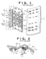
- Figure 1 is a perspective view of a fracture-opening section formed in an interior cover and a reinforcement plate member for reinforcing the fracture-opening section from the inner surface thereof;
- Figure 2 is an explanatory sectional view of a main portion of an airbag before inflation; and
- Figure 3 is an explanatory sectional view of the main portion after inflation of the airbag.
-
- As shown in Figure 1, a
reinforcement plate member 2 for reinforcing a fracture-opening section 1 has a curved shape corresponding to that of the inner wall surface of the fracture-opening section 1. Thereinforcement plate member 2 has a substantially rectangular shape and an area slightly smaller than that of the fracture-opening section 1. Ahinge portion 3 is formed at one end (upper end) of thereinforcement plate member 2 with respect to the transverse direction (shorter-side direction). Thehinge portion 3 extends in the longitudinal direction (longer-side direction) of thereinforcement plate member 2 and is bent outward (in the direction of an arrow) as the airbag inflates. Thehinge portion 3 has anintermediate portion 4 bent substantially perpendicular in a direction away from the back surface of thereinforcement plate member 2, and aconnection portion 5 extending upward substantially perpendicular from the end edge of theintermediate portion 4. - A base portion 6a of a
support member 6 is fixed to theconnection portion 5 by means of nuts andbolts 7. Thesupport member 6 has two support arms 6b, which extend in a direction away from the back surface of thereinforcement plate member 2. As shown in Figure 2, the distal ends of the support arms 6b are fixed to aninterior cover 9 by means of tappingscrews 8, whereby thereinforcement plate member 2 is supported by theinterior cover 9. - A
case support member 10 is fixed to the base portion 6a of thesupport member 6 by means of the nuts andbolts 7. Anairbag case 11 for accommodating an airbag (not shown) is fixed to thecase support member 10 by means of nuts andbolts 12. - A plurality of
depressions 2A are formed, for reinforcement purpose, on thereinforcement plate member 2 in such a manner as to extend in the transverse direction of thereinforcement plate member 2 and to be arranged at predetermined intervals in the longitudinal direction of thereinforcement plate member 2. Blocks ofcoupling holes 2B are formed in thereinforcement plate member 2 while being arranged at predetermined intervals in the transverse and longitudinal directions of thereinforcement plate member 2 over the entire surface thereof. Each block includes a plurality ofcoupling holes 2B extending in the transverse direction of thereinforcement plate member 2 and arranged close to one another in the transverse and longitudinal directions of thereinforcement plate member 2. - For each group of
coupling holes 2B, a plurality ofelongated protrusions 1A are formed on the inner wall surface of the fracture-openingsection 1 of theinterior cover 9 in a manner as to be aligned with thecoupling holes 2B. Theelongated protrusions 1A are engaged with thecorresponding coupling holes 2B, and the tip ends of theprotrusions 1A projecting from the back surface of thereinforcement plate member 2 are melted through application of heat, such that the tip ends are flattened. Thus, thereinforcement plate member 2 is fixedly attached to the inner wall surface of the fracture-openingsection 1. - In the above-described configuration, when the air bag (not shown) inflates, the inflating airbag presses, from inside, the
reinforcement plate member 2. As a result, the fracture-opening section 1 of theinterior cover 9 is fractured along the fracture line and detached from theinterior cover 9. Simultaneously, thehinge portion 3 of thereinforcement plate member 2 having been in the state shown in Figure 2 is bent as shown in Figure 3, and thecase support member 10 having been in the state shown in Figure 2 is bent as shown in Figure 3. As a result, the detached fracture-opening section 1 having been in the state shown in Figure 2 is opened outward as shown in Figure 3, resulting in formation of an opening 9A in theinterior cover 9. The airbag inflates further and projects outward from theinterior cover 9 through the opening 9A. Thus, the intended purpose is achieved. - However, in such a conventional automobile airbag apparatus, when the fracture-opening
section 1 of the interior cover 9 fractures from the fracture groove upon inflation of the airbag, thehinge portion 3 of thereinforcement plate member 2 and thecase support member 10 are bent as shown in Figure 3. Therefore, reaction forces generated when thehinge portion 3 and thecase support member 10 are bent concentrate on a support-member fixing portion 9B of theinterior cover 9 supporting the tappingscrews 8, with the result that the support-member fixing portion 9B may break and separates from theinterior cover 9. As a result, the opening action of the fracture-openingsection 1 including thereinforcement plate member 2 becomes unstable, which may hinder the inflation of the airbag through the opening 9A. - The fracture-opening
section 1 and thereinforcement plate member 2 are united through a process of fitting theelongated protrusions 1A of the fracture-openingsection 1 into thecoupling holes 2B of thereinforcement plate member 2, and melting the tip ends of theprotrusions 1A projecting from the back surface of thereinforcement plate member 2 through application of heat, such that the tip ends are flattened. Since thereinforcement plate member 2 formed of a single metal plate and theinterior cover 9 formed of a synthetic resin such as polypropylene differ in coefficient of linear expansion, the following problems arise. The interior temperature of a vehicle can be as high as 110°C in summer, and as low as -35°C in a cold region in winter. As a result, thereinforcement plate member 2 attached to the back surface of the fracture-openingsection 1 of theinterior cover 9 expands and contracts, resulting in generation of warpage or deformation. In this case, thereinforcement plate member 2 may separate from the back surface of the fracture-openingsection 1 due to breakage of the joining portions therebetween, thereby hindering the fracture of the fracture-openingsection 1 along the fracture groove and hindering the smooth opening of thereinforcement plate member 2 about thehinge portion 3. Further, cracks are formed at the edge portion of the opening 9A formed as a result of fracture of the fracture-openingsection 1, and in the worst case, the fracture-opening section scatters. - Preferred embodiments of the present invention aim to solve the above-mentioned problems, and an object is to provide an improved structure for a reinforcement plate member used in an automobile airbag apparatus, which structure eliminates adverse effects, such as generation of warpage, on the joint portion between a fracture-opening section of an interior cover and a reinforcement plate member, which would otherwise be caused when the reinforcement plate member is formed of a metal having a coefficient of expansion different from that of the fracture-opening section. The structure of such preferred embodiments of the present invention enables smooth fracture and opening of the fracture-opening section, prevents formation of a clearance between the fracture-opening section and the reinforcement plate member, and prevents scattering of the fracture-opening section which would otherwise result from breakage of the joint portion between the fracture-opening section of the reinforcement plate member.
- More generally, according to a first aspect of the present invention, there is provided an automobile airbag apparatus covered with an interior cover of the automobile and comprising:
- an airbag case having an opening portion located in opposition to a back surface of said interior cover;
- an airbag accommodated within said airbag case in a folded state, said airbag being able to be inflated by means of gas from an inflator;
- a fracture-opening section defined in said interior cover to be located in opposition to the opening portion of said airbag case, said fracture-opening section being defined by at least a fragile groove formed from the back surface of said interior cover to surround said fracture-opening section; and
- a reinforcement plate member attached to a back surface of said fracture-opening section through deformation of a portion of said fracture-opening section through application of heat thereto, said reinforcement plate member having a shape corresponding to that of said fracture-opening section: wherein:
- said reinforcement plate member has a main-body portion attached to the back surface of said fracture-opening section and an attachment portion extending from said main-body portion via a hinge portion; and
- a deformation absorbing structure is formed at least in the main-body portion of said reinforcement plate member.
-
- Preferably, said fracture-opening section is defined by a fragile contour portion surrounding said fracture-opening section and a fragile splitting portion for dividing said fracture-opening section into first and second subsections; and first and second reinforcement plate members as aforesaid are attached to back surfaces of said first and second subsections respectively.
- Preferably, at least one reinforcement rib projects from the back surface of said interior cover, said reinforcement rib having engagement holes located at predetermined intervals in its longitudinal direction; said attachment portion of at least one said reinforcement plate member has attachment holes formed in its attachment portion at positions corresponding to those of the engagement holes; and hooks fixed to said airbag case are engaged with the attachment holes and the engagement holes of a respective said attachment portion and reinforcement rib.
- Preferably, said rib has a breakable portion in the vicinity of a connection corner portion through which said reinforcement rib is connected to said interior cover.
- Preferably, for the or each said reinforcement plate member, said deformation absorbing structure includes a plurality of slits formed at predetermined intervals in the longitudinal direction of said reinforcement plate member such that the slits extend in parallel in the transverse direction of said reinforcement plate member.
- Preferably, for the or each said reinforcement plate member, said deformation absorbing structure includes a plurality of slits formed in the main-body portion at predetermined intervals in the longitudinal direction of the main-body portion such that at each interval two slits extend from transverse opposite ends of the main-body portion in the transverse direction with a connection portion left therebetween.
- Preferably, an opening is formed in the main-body portion in the vicinity of each said connection portion.
- Preferably, for the or each said reinforcement plate member, said deformation absorbing structure includes a plurality of slits formed in the attachment portion at predetermined intervals in the longitudinal direction of the attachment portion such that at each interval two slits extend from transverse opposite ends of the attachment portion in the transverse direction with a connection portion left therebetween.
- Preferably, an opening is formed in the attachment portion in the vicinity of each said connection portion.
- Preferably, said interior cover is disposed within an instrument panel, steering wheel, or side pillar of the automobile.
- According to another aspect of the invention, there is provided an airbag apparatus comprising a cover which is arranged to fracture and open upon activation of the airbag, said cover being provided with a reinforcement member which is attached to an opening part of the cover and is arranged to absorb deformation in the reinforcement member.
- Such an airbag apparatus may incorporate any of the features disclosed in the accompanying description, claims, abstract and drawings.
- In preferred embodiments of the present invention, even when the reinforcement plate member is formed of a metal having a coefficient of expansion different from that of the fracture-opening section, the joint portion between the fracture-opening section and the reinforcement plate member does not suffer adverse effects, such as generation of warpage, which would be otherwise caused by variation in temperature. Accordingly, fracture and opening of the fracture-opening section can be effected smoothly, and no clearance is formed between the fracture-opening section and the reinforcement plate member. Further, it becomes possible to prevent scattering of the fracture-opening section, which would otherwise result from breakage of the joint portion.
- Moreover, since deformation of the reinforcement plate member is absorbed, a reinforcement structure for suppressing deformation can be omitted, so that the apparatus can be produced at reduced cost.
- For a better understanding of the invention, and to show how embodiments of the same may be carried into effect, reference will now be made, by way of example, to Figures 4 to 7 of the accompanying diagrammatic drawings, in which:
- Figure 4 is a perspective view of an airbag apparatus for a front passenger seat which employs reinforcement plate members having a structure according to one example of an embodiment of the present invention;
- Figure 5 is a perspective view of the reinforcement plate members in a state in which a fracture-opening section of the airbag apparatus is opened;
- Figures 6a to 6c are views showing one modification of the reinforcement plate members, wherein Figure 6a is a plan view, Figure 6b is a front view, and Figure 6c is a side view; and
- Figure 7 is a front view showing another modification of the reinforcement plate members.
-
- In the Figures, like reference numerals denote like or corresponding parts.
- In the present specification, the terms "front" and "rear" correspond to the front and rear, respectively, of a vehicle, and the terms "right" and "left" correspond to the right-hand and left-hand sides, respectively, of the vehicle.
- As shown in Figures 4 and 5,
reference numeral 21 denotes an instrument panel cover (hereinafter referred to as an "interior cover"), which covers aninstrument panel core 20. Theinstrument panel core 20 and theinterior cover 21 are each moulded from a synthetic resin, such as polypropylene. Theinterior cover 21 is fixedly attached, by appropriate means, such as tapping screws, to theinstrument panel core 20, which, in turn, is fixedly attached to a frame (not shown) of a vehicle. - As shown in Figures 4 and 5, an
accommodation section 23 for accommodating ametallic airbag case 22 is defined by means of a partition member (not shown) located behind theinterior cover 21 and in opposition to a front seat passenger seat. The present embodiment is applied to a vehicle with right-hand drive. A vehicle with left-hand drive employs a mirror image of the configuration of the present embodiment. - The partition member is removably attached to the frame of the vehicle via a plurality of tapping screws in order to facilitate the attachment of the
airbag case 22 and other elements to theinterior cover 21. - A fracture-opening
section 30, which is split open upon inflation of anairbag 27, is formed on theinterior cover 21 in opposition to theaccommodation section 23. The fracture-openingsection 30 assumes a substantially rectangular shape and an area substantially equal to that of anopening portion 22a of theairbag case 22. Through laser processing, which will be described later, a fragile groove serving as acontour portion 30a is formed to surround the fracture-openingsection 30, and a fragile groove serving as a splittingportion 30b is formed at the centre in the front/rear direction so as to extend along the longitudinal direction or right/left direction. The fracture-openingsection 30 can be split into two pieces along the splittingportion 30b. - Two
reinforcement ribs 25 project from the lower surface of theinterior cover 21 such that thereinforcement ribs 25 face each other and extend along the longitudinal direction of the fracture-openingsection 30. Thereinforcement ribs 25 each have a plurality ofengagement holes 25a. Athin portion 26 serving as a breakable portion is formed on eachreinforcement rib 25 in the vicinity of the corner portion where thereinforcement rib 25 is connected to theinterior cover 21. Anairbag 27 is accommodated in a folded condition within theairbag case 22. Theairbag 27 is connected to an unillustrated inflator (gas generator) disposed outside the partition member, by means of a gas feed pipe. A plurality of hooks 36are welded to each of the front and rear surfaces of theairbag case 22. - The fracture-opening
section 30 is formed to assume a size corresponding to that of theopening portion 22a of theairbag case 22 disposed below theinterior cover 21. The fracture-openingsection 30 has a splittingportion 30b, which extends in the right/left direction at a substantially central portion, while dividing the fracture-openingsection 30 into afront subsection 31 and arear subsection 32. - The splitting
portion 30b is biased toward the front passenger seat such that, between the twosubsections section 30, thesubsection 32 located on the side of the front passenger seat of the vehicle is slightly smaller in area than theother subsection 31 located on the side of thewindshield 50 of the vehicle. - The
contour portion 30a and the splittingportion 30b of the fracture-openingsection 30, each formed of a fracture groove, include fragile portions formed by means of a laser (not shown). Specifically, a pulsating laser beam is applied from behind theinterior cover 21 while being moved relatively along thecontour portion 30a and the splittingportion 30b to thereby form the fragile portions. - Horizontal main-
body portions 33a of two reinforcement plate members 33 (e.g. of metal) are fixedly attached to the back surfaces of thesubsections section 30 through melt-joining. Thereinforcement plate members 33 each have anattachment portion 35, which extends downward from ahinge portion 34 continuous with the horizontal main-body portion 33a.Elongated holes 37 are formed in theattachment portion 35 at longitudinal positions corresponding to those of theengagement holes 25a of thereinforcement ribs 25. Thehooks 36 fixed to the front and rear surfaces of theairbag case 22 are engaged with both theelongated holes 37 of theattachment portions 35 and theengagement holes 25a of thereinforcement ribs 25. Moreover, a plurality ofslits 33b serving as a deformation absorbing structure, which is the feature of this embodiment of the present invention, are formed in the horizontal main-body portions 33a of the tworeinforcement plate members 33 in such a manner that theslits 33b are disposed at predetermined intervals in the longitudinal direction of the reinforcement plate members (right/left direction) and extend in parallel in the transverse direction (front/rear direction). - The
slits 33b may be formed at predetermined intervals in the transverse direction of thereinforcement plate member 33 such that theslits 33b are alternately formed from the longitudinal opposite ends of thereinforcement plate member 33 in the longitudinal direction. - The horizontal main-
body portions 33a of thereinforcement plate members 33 have substantially rectangular outer shapes corresponding to those of the front andrear subsections section 30. Excepting portions where theslits 33b are formed, blocks of coupling holes 38 are formed on each of thereinforcement plate members 33 such that the blocks are arranged at predetermined intervals in the transverse and longitudinal directions of thereinforcement plate member 33 over the entire surface thereof. Each block includes a plurality of coupling holes 38 extending in the transverse direction of thereinforcement plate member 33 and arranged close to one another in the transverse and longitudinal directions of thereinforcement plate member 33. - A plurality of
elongated protrusions 39 are formed on the inner wall surfaces of thesubsections section 30 in such a manner as to be aligned with the coupling holes 38 formed in thereinforcement plate members 33. Theelongated protrusions 39 are engaged with the corresponding coupling holes 38, and the tip ends of theprotrusions 39 are melted through application of heat, such that the tip ends are flattened. Thus, thereinforcement plate members 33 are fixedly attached to the corresponding front andrear subsections - Next will be described a method for forming the fracture-opening
section 30 on theinterior cover 21 located in opposition to theaccommodation section 23. - The
contour portion 30a and the splittingportion 30b of the fracture-openingsection 30, which is split open upon inflation of theairbag 27, are formed on theinterior cover 21 by means of a laser. Specifically, a pulsating laser beam (output: 3 kW to 5 kW) of a predetermined frequency (e.g. 7 kHz) emitted from a laser is applied to theinterior cover 21 from behind while being moved relatively at a predetermined speed along the outline edge of thereinforcement plate member 33 fixedly attached to the back surface of theinterior cover 21. Thus, groove-like fragile portions are formed on theinterior cover 21 according to the relative speed of movement of and the pulsation pattern of a laser beam emitted from the laser. - As mentioned above, fragile grooves are formed on the
interior cover 21 in a certain pattern along the entire outline edge of thereinforcement plate member 33. The thus-formed fragile portions define thecontour portion 30a and the splittingportion 30b, along which the fracture-openingsection 30 fractures upon inflation of theairbag 27. - Preferably, the
subsection 32 of the fracture-openingsection 30, which is located on the side of the front passenger seat of a vehicle, assumes such a size as not to project from thehorizontal surface 21b of theinterior cover 21 toward the passenger seat upon inflation of theairbag 27. - The thus-configured airbag apparatus for a front passenger seat according to the present embodiment of the present invention functions in the following manner. Upon collision of the vehicle, an impact force caused by the collision is detected by a sensor. A control unit including a CPU judges whether or not the detected impact force is equal to or higher than a predetermined value. When the control unit judges that the impact force is not lower than the predetermined value, the control unit issues a signal for causing the inflator to generate a predetermined gas. The gas is fed to the
airbag 27 so as to promptly inflate theairbag 27. - The inflating
airbag 27 presses, from inside, the fracture-openingsection 30 of theinterior cover 21 via thereinforcement plate member 33. As a result, the front andrear subsections section 30 are fractured along thecontour portion 30a and the splittingportion 30b and are detached from theinterior cover 21. Since theattachment portions 35 of thereinforcement plate members 33 are engaged with thehooks 36 of theairbag case 22 via theelongated holes 37, thereinforcement plate members 33 slide slightly due to the presence of theelongated holes 37, whereby the upward pressure acting on thereinforcement plate members 33 is reduced. Further, since theslits 33b are formed in the horizontal main-body portions 33a of thereinforcement plate members 33, deformations due to temperature variations can be absorbed, so that breakage of the connection portions between thereinforcement plate members 33 and the front andrear subsections section 30 can be avoided. Accordingly, impact-absorbing performance is improved, and scattering of the front andrear subsections - Further, immediately before completion of inflation of the
airbag 27, thereinforcement ribs 25 break from thethin portions 26 thereof. Subsequently, the front andrear subsections section 30 are fractured along thecontour portion 30a and the splittingportion 30b and are detached from theinterior cover 21. The detached front andrear subsections hinge portions 34 of thereinforcement plate members 33. - Simultaneously, the inflating
airbag 27 projects outward from theinterior cover 21 through the thus-formed opening in theinterior cover 21. Serving as a cushion, theinflated airbag 27 supports a front seat passenger at his/her chest and head, thereby protecting the passenger from the impact force of collision. - According to the thus-configured airbag apparatus for a front passenger seat, the fracture-opening
section 30 is formed on the back surface of theinterior cover 21 such that the fracture-openingsection 30 can be fractured along thecontour portion 30a and the splittingportion 30b composed of fragile portions, which are formed through laser processing. Further, theslits 33b obviate adverse effect on the joint portion which is otherwise caused by the difference in coefficient of expansion between the fracture-openingsection 30 and thereinforcement plate members 33. Therefore, the fracture-openingsection 30 can be reliably opened together with thereinforcement plate members 33, without generation of deformation of the fracture-openingsection 30. Thus, safety is improved. - In the above-described embodiment, each of the
thin portions 26 of thereinforcement ribs 25 is a concave portion formed on the outer surface of eachreinforcement rib 25. However, needless to say, in place of the concave portion, a through hole may be formed as a breakable portion. - Further, in the above-described embodiment, an airbag apparatus for a front-passenger seat has been described. However, other embodiments of the present invention can be applied to airbag apparatus built in the centre portion of a steering wheel, a side pillar, or any other suitable location.
- Figures 6a to 6c show one modification of the
reinforcement plate members 33 as described above. - In the
reinforcement plate members 33 of the present modification, slits 33c serving as a deformation absorbing structure are formed in the horizontal main-body portions 33a of thereinforcement plate members 33 at predetermined intervals along the longitudinal direction of the main-body portions 33a. Specifically, at each longitudinal position, twoslits 33c are formed from the transverse opposite ends of each main-body portion 33a in the transverse direction, with aconnection portion 33d left therebetween. Further,openings 33e are formed in the main-body portion 33a in the vicinity of and on opposite sides of theconnection portion 33d. - Moreover, the main-
body portions 33a of thereinforcement plate members 33 havecoupling holes 38, which receive theprotrusions 39 formed on the back surface of the fracture-opening section. The area of eachcoupling hole 38 is rendered greater than a welding area A in which the tip end portions of theprotrusions 39 are melted and spread through application of heat. - In the
reinforcement plate members 33, theslits body portions 33a absorb deformation (expansion and contraction) of thereinforcement plate members 33 that is due to variation in the interior temperature of the vehicle. Further, since the area of eachcoupling hole 38 is greater than the welding area A, theprotrusions 39 can move within the coupling holes 38 when thereinforcement plate members 33 deforms; i.e., expands or contracts. Thus, breakage of the joint portions can be prevented. - Figure 7 shows another modification of the
reinforcement plate members 33. - In the
reinforcement plate members 33 according to the modification of Figure 7, slits 35b are formed in theattachment portions 35 of thereinforcement plate members 33 at predetermined intervals along the longitudinal direction of theattachment portions 35. Specifically, at each longitudinal position, twoslits 35b are formed from the opposite ends of eachattachment portion 35 in the transverse direction, with aconnection portion 35a left therebetween. Further,openings 35c are formed in theattachment portion 35 in the vicinity of and on opposite sides of theconnection portion 35a. In Figure 7,reference numeral 37 denotes each of engagement holes with which thehooks 36 of theairbag case 22 are engaged. - Since the structures of other portions are the same as those of the above-described embodiment, these portions are denoted by the same reference numerals, and their descriptions are not repeated.
- In the present modification, since a deformation absorbing structure such as slits are formed in the attachment portions of the reinforcement plate members as well, the deformation absorbing action for absorbing expansion and contraction of the reinforcement plate members can be improved.
- The airbag apparatus described in the above-described embodiments has a fracture-opening section which is divided at the centre into two subsections. However, the present invention is not limited thereto. For example, effects similar to those obtained in the above-described embodiments can be obtained even in the case in which other embodiments of the present invention are applied to an airbag having an undividable fracture-opening section and a single reinforcement plate member.
- In this specification, the verb "comprise" has its normal dictionary meaning, to denote non-exclusive inclusion. That is, use of the word "comprise" (or any of its derivatives) to include one feature or more, does not exclude the possibility of also including further features.
- The reader's attention is directed to all and any priority documents identified in connection with this application and to all and any papers and documents which are filed concurrently with or previous to this specification in connection with this application and which are open to public inspection with this specification, and the contents of all such papers and documents are incorporated herein by reference.
- All of the features disclosed in this specification (including any accompanying claims, abstract and drawings), and/or all of the steps of any method or process so disclosed, may be combined in any combination, except combinations where at least some of such features and/or steps are mutually exclusive.
- Each feature disclosed in this specification (including any accompanying claims, abstract and drawings), may be replaced by alternative features serving the same, equivalent or similar purpose, unless expressly stated otherwise. Thus, unless expressly stated otherwise, each feature disclosed is one example only of a generic series of equivalent or similar features.
- The invention is not restricted to the details of the foregoing embodiment(s). The invention extends to any novel one, or any novel combination, of the features disclosed in this specification (including any accompanying claims, abstract and drawings), or to any novel one, or any novel combination, of the steps of any method or process so disclosed.
Claims (12)
- An automobile airbag apparatus covered with an interior cover (21) of the automobile and comprising:wherein:an airbag case (22) having an opening portion (22a) located in opposition to a back surface of said interior cover (21);an airbag (27) accommodated within said airbag case (22) in a folded state, said airbag (27) being able to be inflated by means of gas from an inflator;a fracture-opening section (30) defined in said interior cover (21) to be located in opposition to the opening portion (22a) of said airbag case (22), said fracture-opening section (30) being defined by at least a fragile groove (30a) formed from the back surface of said interior cover (21) to surround said fracture-opening section (30); anda reinforcement plate member (33) attached to a back surface of said fracture-opening section (30) through deformation of a portion of said fracture-opening section (30) through application of heat thereto, said reinforcement plate member (33) having a shape corresponding to that of said fracture-opening section (30):said reinforcement plate member (33) has a main-body portion (33a) attached to the back surface of said fracture-opening section (30) and an attachment portion (35) extending from said main-body portion (33a) via a hinge portion (34); anda deformation absorbing structure is formed at least in the main-body portion (33a) of said reinforcement plate member (33).
- An automobile airbag apparatus according to claim 1, wherein:said fracture-opening section (30) is defined by a fragile contour portion (30a) surrounding said fracture-opening section (30) and a fragile splitting portion (30b) for dividing said fracture-opening section (30) into first and second subsections (31,32); andfirst and second reinforcement plate members (33) as aforesaid are attached to back surfaces of said first and second subsections (31,32) respectively.
- An automobile airbag apparatus according to claim 1 or 2, wherein:at least one reinforcement rib (25) projects from the back surface of said interior cover (21), said reinforcement rib (25) having engagement holes (25a) located at predetermined intervals in its longitudinal direction;said attachment portion (35) of at least one said reinforcement plate member (33) has attachment holes (37) formed in its attachment portion (35) at positions corresponding to those of the engagement holes (25a); andhooks (36) fixed to said airbag case (22) are engaged with the attachment holes (37) and the engagement holes (25a) of a respective said attachment portion (35) and reinforcement rib (25).
- An automobile airbag apparatus according to claim 3, wherein said reinforcement rib (25) has a breakable portion (26) in the vicinity of a connection corner portion through which said reinforcement rib (25) is connected to said interior cover (21).
- An automobile airbag apparatus according to any of the preceding claims, wherein, for the or each said reinforcement plate member (33), said deformation absorbing structure includes a plurality of slits (33b) formed at predetermined intervals in the longitudinal direction of said reinforcement plate member (33) such that the slits (33b) extend in parallel in the transverse direction of said reinforcement plate member (33).
- An automobile airbag apparatus according to any of the preceding claims, wherein, for the or each said reinforcement plate member (33), said deformation absorbing structure includes a plurality of slits (33c) formed in the main-body portion (33a) at predetermined intervals in the longitudinal direction of the main-body portion (33a) such that at each interval two slits (33c) extend from transverse opposite ends of the main-body portion (33a) in the transverse direction with a connection portion (33d) left therebetween.
- An automobile airbag apparatus according to claim 6, wherein an opening (33e) is formed in the main-body portion (33a) in the vicinity of each said connection portion (33d).
- An automobile airbag apparatus according to any of the preceding claims, wherein, for the or each said reinforcement plate member (33), said deformation absorbing structure includes a plurality of slits (35b) formed in the attachment portion (35) at predetermined intervals in the longitudinal direction of the attachment portion (35) such that at each interval two slits (35b) extend from transverse opposite ends of the attachment portion (35) in the transverse direction with a connection portion (35a) left therebetween.
- An automobile airbag apparatus according to claim 8, wherein an opening (35c) is formed in the attachment portion (35) in the vicinity of each said connection portion.
- An automobile airbag apparatus according to any of the preceding claims, wherein said interior cover (21) is disposed within an instrument panel, steering wheel, or side pillar of the automobile.
- An airbag apparatus comprising a cover (21) which is arranged to fracture and open upon activation of the airbag (27), said cover (21) being provided with a reinforcement member (33) which is attached to an opening part (30) of the cover (21) and is arranged to absorb deformation in the reinforcement member (33).
- An airbag apparatus according to claim 11 and further incorporating any of the features disclosed in the accompanying description, claims, abstract and drawings.
Applications Claiming Priority (2)
| Application Number | Priority Date | Filing Date | Title |
|---|---|---|---|
| JP2000125999A JP3723044B2 (en) | 2000-01-28 | 2000-04-26 | Structure of reinforcing plate in automotive airbag device |
| JP2000125999 | 2000-04-26 |
Publications (3)
| Publication Number | Publication Date |
|---|---|
| EP1149742A2 true EP1149742A2 (en) | 2001-10-31 |
| EP1149742A3 EP1149742A3 (en) | 2003-03-19 |
| EP1149742B1 EP1149742B1 (en) | 2009-08-05 |
Family
ID=18635856
Family Applications (1)
| Application Number | Title | Priority Date | Filing Date |
|---|---|---|---|
| EP01303776A Expired - Lifetime EP1149742B1 (en) | 2000-04-26 | 2001-04-26 | Airbag apparatus |
Country Status (4)
| Country | Link |
|---|---|
| US (1) | US6761375B2 (en) |
| EP (1) | EP1149742B1 (en) |
| AT (1) | ATE438541T1 (en) |
| DE (1) | DE60139438D1 (en) |
Cited By (2)
| Publication number | Priority date | Publication date | Assignee | Title |
|---|---|---|---|---|
| EP1302373A1 (en) * | 2001-10-10 | 2003-04-16 | Sanko Gosei Kabushiki Kaisha | Airbag cover with a tear seam |
| WO2004067335A1 (en) * | 2003-01-29 | 2004-08-12 | Faurecia Innenraum Systeme Gmbh | Interior trimming piece |
Families Citing this family (19)
| Publication number | Priority date | Publication date | Assignee | Title |
|---|---|---|---|---|
| JP3973029B2 (en) * | 2002-03-28 | 2007-09-05 | 三光合成株式会社 | Airbag device for automobile |
| JP4011441B2 (en) * | 2002-05-10 | 2007-11-21 | ダイハツ工業株式会社 | Instrument panel structure of vehicle |
| JP3855867B2 (en) * | 2002-07-10 | 2006-12-13 | 日産自動車株式会社 | Interior parts for vehicles |
| US20040164524A1 (en) * | 2002-12-10 | 2004-08-26 | Calsonic Kansei Corporation | Airbag apparatus for vehicle |
| FR2857923B1 (en) * | 2003-07-23 | 2006-01-27 | Faurecia Interieur Ind | DASHBOARD COMPRISING A TRAPPE RETAINED BY BRIDGES |
| JP2005067466A (en) * | 2003-08-26 | 2005-03-17 | Takata Corp | Occupant-leg protection device |
| US20070080521A1 (en) * | 2003-12-15 | 2007-04-12 | Faurecia Interieur Industrie | Motor vehicle part including an airbag safety device, and a method of assembling such a part |
| DE102004009914A1 (en) * | 2004-02-20 | 2005-10-06 | Daimlerchrysler Ag | Airbag cover for an airbag of a motor vehicle |
| JP4838539B2 (en) * | 2005-05-31 | 2011-12-14 | 三光合成株式会社 | Airbag device for vehicle |
| JP4831999B2 (en) * | 2005-05-31 | 2011-12-07 | 三光合成株式会社 | VEHICLE AIRBACK DEVICE AND AIRBACK COVER |
| JP2007038868A (en) * | 2005-08-03 | 2007-02-15 | Takata Corp | Cover for air bag device and air bag device |
| US20070057498A1 (en) * | 2005-09-12 | 2007-03-15 | Hyundai Mobis Co., Ltd. | Airbag device |
| US9165920B2 (en) * | 2005-10-15 | 2015-10-20 | Globalfoundries Singapore Pte. Ltd. | Tunable protection system for integrated circuits |
| JP4746409B2 (en) | 2005-11-17 | 2011-08-10 | 三光合成株式会社 | Airbag device for vehicle |
| US7234724B1 (en) | 2006-09-26 | 2007-06-26 | International Automotive Components Group North America, Inc. | Airbag assembly with angled keyway |
| US7770914B2 (en) * | 2007-07-31 | 2010-08-10 | Autoliv Asp, Inc. | Passenger airbag mounting apparatus |
| US9421933B1 (en) * | 2015-04-21 | 2016-08-23 | Ford Global Technologies, Llc | Active glove box door with intermediate skeleton member |
| JP6695249B2 (en) * | 2016-09-27 | 2020-05-20 | マレリ株式会社 | Air bag grid and manufacturing method thereof |
| HUE056064T2 (en) * | 2018-01-22 | 2022-01-28 | Motherson Innovations Co Ltd | Air bag guiding device for guiding a vehicle airbag, airbag unit with such an airbag guide and internal cladding component and method for producing a corresponding internal cladding component, comprising such an airbag guide |
Citations (2)
| Publication number | Priority date | Publication date | Assignee | Title |
|---|---|---|---|---|
| JPH11198752A (en) | 1998-01-19 | 1999-07-27 | Sanko Gosei Ltd | Air bag device for assistant seat |
| WO1999046152A1 (en) | 1998-03-09 | 1999-09-16 | Lear Automotive Dearborn, Inc. | Instrument panel seamless airbag cover |
Family Cites Families (37)
| Publication number | Priority date | Publication date | Assignee | Title |
|---|---|---|---|---|
| JPS52116537A (en) | 1976-03-26 | 1977-09-30 | Toyota Motor Corp | Expansion type passenger restricting device for automobile or the like |
| US5082310A (en) * | 1989-11-06 | 1992-01-21 | Tip Engineering Group, Inc. | Arrangement for providing an air bag deployment opening |
| JPH03279055A (en) | 1990-03-28 | 1991-12-10 | Mazda Motor Corp | Automotive air bag device |
| JP3165492B2 (en) | 1992-01-30 | 2001-05-14 | マツダ株式会社 | Automotive airbag equipment |
| JPH06144142A (en) | 1992-10-30 | 1994-05-24 | Toyoda Gosei Co Ltd | Pad for air bag device |
| US5322324A (en) * | 1993-08-03 | 1994-06-21 | Morton International, Inc. | Cover for an inflatable air bag housing |
| US5411288A (en) | 1993-11-03 | 1995-05-02 | Trw Vehicle Safety Systems Inc. | Air bag module door assembly |
| JPH07172256A (en) | 1993-12-22 | 1995-07-11 | Mitsubishi Motors Corp | Vehicle air bag device |
| JP3337821B2 (en) | 1994-04-28 | 2002-10-28 | 株式会社イノアックコーポレーション | Structure of the airbag section of the instrument panel |
| US5816609A (en) * | 1994-06-13 | 1998-10-06 | Textron Automative Company, Inc. | Trim panel having air bag door |
| US6012735A (en) * | 1994-06-13 | 2000-01-11 | Textron Automotive Company | Trim panel having air bag door |
| US5569959A (en) | 1994-06-29 | 1996-10-29 | David Textron, Inc. | Closure for an air bag assembly |
| US5456487A (en) * | 1994-08-22 | 1995-10-10 | Chrysler Corporation | Passenger air bag door |
| US5685560A (en) | 1995-01-19 | 1997-11-11 | Nihon Plast Co., Ltd. | Airbag module cover assembly |
| JP2950774B2 (en) | 1995-06-05 | 1999-09-20 | 株式会社イノアックコーポレーション | Airbag door structure for vehicle compartment side members |
| US5738367A (en) | 1995-06-15 | 1998-04-14 | Tip Engineering Group, Inc. | Automotive interior trim piece having an arrangement for forming an air bag deployment opening |
| DE69615091T2 (en) | 1995-06-16 | 2002-06-20 | Toyoda Gosei Co., Ltd. | Interior trim part for a motor vehicle with an airbag and manufacturing method therefor |
| US5549324A (en) * | 1995-07-11 | 1996-08-27 | Davidson Textron Inc. | Construction and method of forming a door assembly for an air system |
| JP3728778B2 (en) | 1995-09-22 | 2005-12-21 | 豊田合成株式会社 | Air bag cover |
| JP3201243B2 (en) | 1995-12-12 | 2001-08-20 | 豊田合成株式会社 | Automotive interior parts with lid for airbag |
| JP2973912B2 (en) | 1996-02-09 | 1999-11-08 | トヨタ自動車株式会社 | Passenger seat airbag device and bag folding method applied thereto |
| JP3708638B2 (en) | 1996-07-31 | 2005-10-19 | 三ツ星ベルト株式会社 | Instrument panel with integrated airbag |
| JP3321531B2 (en) * | 1996-08-26 | 2002-09-03 | 株式会社イノアックコーポレーション | Instrument panel with airbag door |
| US6203056B1 (en) * | 1997-06-09 | 2001-03-20 | Textron Automotive Company Inc. | Apparatus for deploying an airbag through a hard panel |
| US5863064A (en) | 1997-08-14 | 1999-01-26 | Textron Autmotive Company Inc. | Skin for automotive air bag cover panel formed by casting different plastic materials |
| US6076851A (en) | 1998-05-01 | 2000-06-20 | Lear Corporation | Airbag surround for seamless instrument panel |
| JP2000118343A (en) * | 1998-10-13 | 2000-04-25 | Toyota Motor Corp | Instrument panel with integrated airbag door |
| US6070901A (en) | 1998-10-19 | 2000-06-06 | Ford Global Technologies, Inc. | Automotive instrument panel having an integral airbag |
| US6079734A (en) * | 1998-11-23 | 2000-06-27 | Larry J. Winget | Air bag cover assembly having a switch module and method of making same |
| US6161865A (en) * | 1999-05-28 | 2000-12-19 | Autoliv Asp, Inc. | Interlocking airbag attachment and module assembly |
| JP4120132B2 (en) * | 1999-08-19 | 2008-07-16 | タカタ株式会社 | Air bag device and its case |
| JP3717043B2 (en) * | 1999-10-21 | 2005-11-16 | 三光合成株式会社 | Airbag device for passenger seat |
| JP2001206180A (en) | 2000-01-28 | 2001-07-31 | Sanko Gosei Ltd | Air bag device for automobile |
| JP2001253311A (en) | 2000-03-09 | 2001-09-18 | Takata Corp | Air bag device for front passenger seat |
| US6340170B1 (en) * | 2000-03-28 | 2002-01-22 | Trw Vehicle Safety Systems Inc. | Actuatable knee bolster |
| EP1151898B1 (en) | 2000-04-28 | 2004-02-25 | Inoac Corporation | Tear structure of air bag door |
| JP2002029356A (en) | 2000-05-12 | 2002-01-29 | Sanko Gosei Ltd | Air bag device for front passenger seat |
-
2001
- 2001-04-25 US US09/843,083 patent/US6761375B2/en not_active Expired - Lifetime
- 2001-04-26 EP EP01303776A patent/EP1149742B1/en not_active Expired - Lifetime
- 2001-04-26 AT AT01303776T patent/ATE438541T1/en not_active IP Right Cessation
- 2001-04-26 DE DE60139438T patent/DE60139438D1/en not_active Expired - Fee Related
Patent Citations (2)
| Publication number | Priority date | Publication date | Assignee | Title |
|---|---|---|---|---|
| JPH11198752A (en) | 1998-01-19 | 1999-07-27 | Sanko Gosei Ltd | Air bag device for assistant seat |
| WO1999046152A1 (en) | 1998-03-09 | 1999-09-16 | Lear Automotive Dearborn, Inc. | Instrument panel seamless airbag cover |
Cited By (2)
| Publication number | Priority date | Publication date | Assignee | Title |
|---|---|---|---|---|
| EP1302373A1 (en) * | 2001-10-10 | 2003-04-16 | Sanko Gosei Kabushiki Kaisha | Airbag cover with a tear seam |
| WO2004067335A1 (en) * | 2003-01-29 | 2004-08-12 | Faurecia Innenraum Systeme Gmbh | Interior trimming piece |
Also Published As
| Publication number | Publication date |
|---|---|
| DE60139438D1 (en) | 2009-09-17 |
| EP1149742B1 (en) | 2009-08-05 |
| US6761375B2 (en) | 2004-07-13 |
| US20010035635A1 (en) | 2001-11-01 |
| EP1149742A3 (en) | 2003-03-19 |
| ATE438541T1 (en) | 2009-08-15 |
Similar Documents
| Publication | Publication Date | Title |
|---|---|---|
| EP1149742B1 (en) | Airbag apparatus | |
| EP1388467B1 (en) | Airbag apparatus for automobile | |
| US20030184063A1 (en) | Airbag apparatus for automobile | |
| US7165782B2 (en) | Airbag apparatus for automobile | |
| EP1153809A1 (en) | Airbag apparatus | |
| US7484752B2 (en) | Airbag apparatus for automobile | |
| US7168731B2 (en) | Airbag apparatus for automobile | |
| EP1738970B1 (en) | Airbag apparatus for vehicle and airbag cover | |
| EP1302373B1 (en) | Airbag cover with a tear seam | |
| US6857654B2 (en) | Passenger restraining apparatus for vehicle | |
| JP3923004B2 (en) | Cover body of airbag device | |
| JP3723044B2 (en) | Structure of reinforcing plate in automotive airbag device | |
| JP2001206180A (en) | Air bag device for automobile | |
| CA2330750C (en) | Airbag tear seam | |
| JP3694860B2 (en) | Airbag device for automobile | |
| JP2003146172A (en) | Rapture opening part structure of airbag equipment for automobile | |
| JP2538159B2 (en) | Airbag cover body | |
| JP4279447B2 (en) | Airbag device | |
| JP3654347B2 (en) | Airbag device for automobile | |
| JP3668702B2 (en) | Airbag device for automobile | |
| EP1251039B1 (en) | Airbag apparatus | |
| JP4051250B2 (en) | Improved structure of break opening in automotive airbag device | |
| KR20010069681A (en) | integrated seamless passenger airbag door system | |
| JPH05170043A (en) | Air bag cover body | |
| JP2001055106A (en) | Air bag device for automobile |
Legal Events
| Date | Code | Title | Description |
|---|---|---|---|
| PUAI | Public reference made under article 153(3) epc to a published international application that has entered the european phase |
Free format text: ORIGINAL CODE: 0009012 |
|
| AK | Designated contracting states |
Kind code of ref document: A2 Designated state(s): AT BE CH CY DE DK ES FI FR GB GR IE IT LI LU MC NL PT SE TR |
|
| AX | Request for extension of the european patent |
Free format text: AL;LT;LV;MK;RO;SI |
|
| PUAL | Search report despatched |
Free format text: ORIGINAL CODE: 0009013 |
|
| AK | Designated contracting states |
Kind code of ref document: A3 Designated state(s): AT BE CH CY DE DK ES FI FR GB GR IE IT LI LU MC NL PT SE TR |
|
| AX | Request for extension of the european patent |
Extension state: AL LT LV MK RO SI |
|
| 17P | Request for examination filed |
Effective date: 20030919 |
|
| AKX | Designation fees paid |
Designated state(s): AT BE CH CY DE DK ES FI FR GB GR IE IT LI LU MC NL PT SE TR |
|
| 17Q | First examination report despatched |
Effective date: 20070823 |
|
| GRAP | Despatch of communication of intention to grant a patent |
Free format text: ORIGINAL CODE: EPIDOSNIGR1 |
|
| GRAS | Grant fee paid |
Free format text: ORIGINAL CODE: EPIDOSNIGR3 |
|
| GRAA | (expected) grant |
Free format text: ORIGINAL CODE: 0009210 |
|
| AK | Designated contracting states |
Kind code of ref document: B1 Designated state(s): AT BE CH CY DE DK ES FI FR GB GR IE IT LI LU MC NL PT SE TR |
|
| REG | Reference to a national code |
Ref country code: GB Ref legal event code: FG4D |
|
| REG | Reference to a national code |
Ref country code: CH Ref legal event code: EP |
|
| REG | Reference to a national code |
Ref country code: IE Ref legal event code: FG4D |
|
| REF | Corresponds to: |
Ref document number: 60139438 Country of ref document: DE Date of ref document: 20090917 Kind code of ref document: P |
|
| PG25 | Lapsed in a contracting state [announced via postgrant information from national office to epo] |
Ref country code: ES Free format text: LAPSE BECAUSE OF FAILURE TO SUBMIT A TRANSLATION OF THE DESCRIPTION OR TO PAY THE FEE WITHIN THE PRESCRIBED TIME-LIMIT Effective date: 20091116 Ref country code: SE Free format text: LAPSE BECAUSE OF FAILURE TO SUBMIT A TRANSLATION OF THE DESCRIPTION OR TO PAY THE FEE WITHIN THE PRESCRIBED TIME-LIMIT Effective date: 20090805 Ref country code: AT Free format text: LAPSE BECAUSE OF FAILURE TO SUBMIT A TRANSLATION OF THE DESCRIPTION OR TO PAY THE FEE WITHIN THE PRESCRIBED TIME-LIMIT Effective date: 20090805 Ref country code: FI Free format text: LAPSE BECAUSE OF FAILURE TO SUBMIT A TRANSLATION OF THE DESCRIPTION OR TO PAY THE FEE WITHIN THE PRESCRIBED TIME-LIMIT Effective date: 20090805 |
|
| NLV1 | Nl: lapsed or annulled due to failure to fulfill the requirements of art. 29p and 29m of the patents act | ||
| PG25 | Lapsed in a contracting state [announced via postgrant information from national office to epo] |
Ref country code: NL Free format text: LAPSE BECAUSE OF FAILURE TO SUBMIT A TRANSLATION OF THE DESCRIPTION OR TO PAY THE FEE WITHIN THE PRESCRIBED TIME-LIMIT Effective date: 20090805 |
|
| PG25 | Lapsed in a contracting state [announced via postgrant information from national office to epo] |
Ref country code: PT Free format text: LAPSE BECAUSE OF FAILURE TO SUBMIT A TRANSLATION OF THE DESCRIPTION OR TO PAY THE FEE WITHIN THE PRESCRIBED TIME-LIMIT Effective date: 20091205 |
|
| PG25 | Lapsed in a contracting state [announced via postgrant information from national office to epo] |
Ref country code: DK Free format text: LAPSE BECAUSE OF FAILURE TO SUBMIT A TRANSLATION OF THE DESCRIPTION OR TO PAY THE FEE WITHIN THE PRESCRIBED TIME-LIMIT Effective date: 20090805 |
|
| PLBE | No opposition filed within time limit |
Free format text: ORIGINAL CODE: 0009261 |
|
| STAA | Information on the status of an ep patent application or granted ep patent |
Free format text: STATUS: NO OPPOSITION FILED WITHIN TIME LIMIT |
|
| PG25 | Lapsed in a contracting state [announced via postgrant information from national office to epo] |
Ref country code: BE Free format text: LAPSE BECAUSE OF FAILURE TO SUBMIT A TRANSLATION OF THE DESCRIPTION OR TO PAY THE FEE WITHIN THE PRESCRIBED TIME-LIMIT Effective date: 20090805 |
|
| 26N | No opposition filed |
Effective date: 20100507 |
|
| PG25 | Lapsed in a contracting state [announced via postgrant information from national office to epo] |
Ref country code: GR Free format text: LAPSE BECAUSE OF FAILURE TO SUBMIT A TRANSLATION OF THE DESCRIPTION OR TO PAY THE FEE WITHIN THE PRESCRIBED TIME-LIMIT Effective date: 20091106 |
|
| PG25 | Lapsed in a contracting state [announced via postgrant information from national office to epo] |
Ref country code: MC Free format text: LAPSE BECAUSE OF NON-PAYMENT OF DUE FEES Effective date: 20100430 |
|
| REG | Reference to a national code |
Ref country code: CH Ref legal event code: PL |
|
| REG | Reference to a national code |
Ref country code: FR Ref legal event code: ST Effective date: 20101230 |
|
| PG25 | Lapsed in a contracting state [announced via postgrant information from national office to epo] |
Ref country code: IE Free format text: LAPSE BECAUSE OF NON-PAYMENT OF DUE FEES Effective date: 20100426 |
|
| PG25 | Lapsed in a contracting state [announced via postgrant information from national office to epo] |
Ref country code: DE Free format text: LAPSE BECAUSE OF NON-PAYMENT OF DUE FEES Effective date: 20101103 Ref country code: CH Free format text: LAPSE BECAUSE OF NON-PAYMENT OF DUE FEES Effective date: 20100430 Ref country code: LI Free format text: LAPSE BECAUSE OF NON-PAYMENT OF DUE FEES Effective date: 20100430 |
|
| PG25 | Lapsed in a contracting state [announced via postgrant information from national office to epo] |
Ref country code: IT Free format text: LAPSE BECAUSE OF FAILURE TO SUBMIT A TRANSLATION OF THE DESCRIPTION OR TO PAY THE FEE WITHIN THE PRESCRIBED TIME-LIMIT Effective date: 20090805 |
|
| PG25 | Lapsed in a contracting state [announced via postgrant information from national office to epo] |
Ref country code: FR Free format text: LAPSE BECAUSE OF NON-PAYMENT OF DUE FEES Effective date: 20100430 |
|
| PG25 | Lapsed in a contracting state [announced via postgrant information from national office to epo] |
Ref country code: CY Free format text: LAPSE BECAUSE OF FAILURE TO SUBMIT A TRANSLATION OF THE DESCRIPTION OR TO PAY THE FEE WITHIN THE PRESCRIBED TIME-LIMIT Effective date: 20090805 |
|
| PG25 | Lapsed in a contracting state [announced via postgrant information from national office to epo] |
Ref country code: LU Free format text: LAPSE BECAUSE OF NON-PAYMENT OF DUE FEES Effective date: 20100426 |
|
| PG25 | Lapsed in a contracting state [announced via postgrant information from national office to epo] |
Ref country code: TR Free format text: LAPSE BECAUSE OF FAILURE TO SUBMIT A TRANSLATION OF THE DESCRIPTION OR TO PAY THE FEE WITHIN THE PRESCRIBED TIME-LIMIT Effective date: 20090805 |
|
| PGFP | Annual fee paid to national office [announced via postgrant information from national office to epo] |
Ref country code: GB Payment date: 20200728 Year of fee payment: 20 |
|
| REG | Reference to a national code |
Ref country code: GB Ref legal event code: PE20 Expiry date: 20210425 |
|
| PG25 | Lapsed in a contracting state [announced via postgrant information from national office to epo] |
Ref country code: GB Free format text: LAPSE BECAUSE OF EXPIRATION OF PROTECTION Effective date: 20210425 |