EP1149706A2 - Ink tank, ink jet recording head, ink jet cartridge, and ink jet recording apparatus - Google Patents
Ink tank, ink jet recording head, ink jet cartridge, and ink jet recording apparatus Download PDFInfo
- Publication number
- EP1149706A2 EP1149706A2 EP01110244A EP01110244A EP1149706A2 EP 1149706 A2 EP1149706 A2 EP 1149706A2 EP 01110244 A EP01110244 A EP 01110244A EP 01110244 A EP01110244 A EP 01110244A EP 1149706 A2 EP1149706 A2 EP 1149706A2
- Authority
- EP
- European Patent Office
- Prior art keywords
- ink
- negative
- gas
- ink jet
- jet recording
- Prior art date
- Legal status (The legal status is an assumption and is not a legal conclusion. Google has not performed a legal analysis and makes no representation as to the accuracy of the status listed.)
- Granted
Links
Images






Classifications
-
- B—PERFORMING OPERATIONS; TRANSPORTING
- B41—PRINTING; LINING MACHINES; TYPEWRITERS; STAMPS
- B41J—TYPEWRITERS; SELECTIVE PRINTING MECHANISMS, i.e. MECHANISMS PRINTING OTHERWISE THAN FROM A FORME; CORRECTION OF TYPOGRAPHICAL ERRORS
- B41J2/00—Typewriters or selective printing mechanisms characterised by the printing or marking process for which they are designed
- B41J2/005—Typewriters or selective printing mechanisms characterised by the printing or marking process for which they are designed characterised by bringing liquid or particles selectively into contact with a printing material
- B41J2/01—Ink jet
- B41J2/17—Ink jet characterised by ink handling
- B41J2/175—Ink supply systems ; Circuit parts therefor
- B41J2/17503—Ink cartridges
- B41J2/17556—Means for regulating the pressure in the cartridge
-
- B—PERFORMING OPERATIONS; TRANSPORTING
- B41—PRINTING; LINING MACHINES; TYPEWRITERS; STAMPS
- B41J—TYPEWRITERS; SELECTIVE PRINTING MECHANISMS, i.e. MECHANISMS PRINTING OTHERWISE THAN FROM A FORME; CORRECTION OF TYPOGRAPHICAL ERRORS
- B41J2/00—Typewriters or selective printing mechanisms characterised by the printing or marking process for which they are designed
- B41J2/005—Typewriters or selective printing mechanisms characterised by the printing or marking process for which they are designed characterised by bringing liquid or particles selectively into contact with a printing material
- B41J2/01—Ink jet
- B41J2/17—Ink jet characterised by ink handling
- B41J2/175—Ink supply systems ; Circuit parts therefor
- B41J2/17503—Ink cartridges
- B41J2/17506—Refilling of the cartridge
- B41J2/17509—Whilst mounted in the printer
-
- B—PERFORMING OPERATIONS; TRANSPORTING
- B41—PRINTING; LINING MACHINES; TYPEWRITERS; STAMPS
- B41J—TYPEWRITERS; SELECTIVE PRINTING MECHANISMS, i.e. MECHANISMS PRINTING OTHERWISE THAN FROM A FORME; CORRECTION OF TYPOGRAPHICAL ERRORS
- B41J2/00—Typewriters or selective printing mechanisms characterised by the printing or marking process for which they are designed
- B41J2/005—Typewriters or selective printing mechanisms characterised by the printing or marking process for which they are designed characterised by bringing liquid or particles selectively into contact with a printing material
- B41J2/01—Ink jet
- B41J2/17—Ink jet characterised by ink handling
- B41J2/175—Ink supply systems ; Circuit parts therefor
- B41J2/17596—Ink pumps, ink valves
Definitions
- the present invention relates to an ink tank, an ink jet recording head, an ink jet cartridge, and an ink jet recording apparatus.
- the present invention is applicable to general print apparatuses as recording apparatuses, copiers, facsimile terminal equipment having a communication system, apparatuses such as word processors which have a print section, and industrial print apparatuses combined with various processing apparatuses.
- serial-scan-based ink jet recording apparatuses comprise a carriage that is movable in a main scan direction, an ink jet recording head acting as recording means, and an ink tank acting as an ink container, both the ink jet recording head and the ink tank being replaceably mounted on the carriage.
- the recording head and the ink tank are connected together via an ink passage.
- an image can sequentially be recorded on a recorded medium such as recording paper by repeating a main scan of the carriage with the recording head and the ink tank mounted thereon and a subscan of the recorded medium.
- a possible method of supplying an ink to the ink tank of the ink jet recording apparatus is, for example, to suck and supply the ink by pressurizing the ink to introduce negative pressure into the ink.
- a storage ink tank 20 acting as a sub-ink tank has an ink jet recording head 20a (hereafter simply referred to as a "recording head") capable of ejecting an ink for recording and is removably mounted on a carriage (not shown).
- the recording head 20a ejects the ink from the storage ink tank 20 through an ink ejecting port in a nozzle 44 based on image information.
- the storage ink tank 20 has an ink supplying port 20f for supplying the ink from the storage ink tank 20 to the recording head 20a.
- the nozzle 44 in the recording head 20a includes an ejection energy generating means for generating energy required to eject the ink.
- the ejection energy generating means may comprise an electrothermal converter for generating thermal energy.
- the carriage is moved by an appropriate movement mechanism in the main scan direction shown by arrows 28 and 35. Further, recorded media are conveyed in a subscan direction crossing the main scan direction.
- an image can sequentially be recorded on the recorded medium by repeating a main scan of the carriage with the recording head 20a and the storage ink tank 20 mounted thereon and a subscan of the recorded medium.
- the storage ink tank 20 has a suction port 53 and an ink intake port 20b formed in a side thereof.
- the suction port 53 is in communication with the interior of the storage ink tank 20 via a suction passage 53a, and a gas transmitting member 48 is provided at the site of the opening of the suction passage 53a in the storage ink tank 20.
- the gas transmitting member 48 has, as a gas-liquid separating means, a function of transmitting gases therethrough while not transmitting inks therethrough.
- the gas transmitting member 48 preferably comprise a thin sheet formed of an ethylene tetrafluorice resin, a similar porous resin material, or the like.
- the storage ink tank 20 has an ink absorber 41a accommodated therein, for sucking and holding the ink.
- the storage ink tank 20 includes a filter 103 and a valve 104 in the supplying port 20f.
- the valve 104 is shaped like a seat and has its proximal end welded to the filter 103.
- the valve 104 functions to open and close the supplying port 20f depending on the internal pressure of the storage ink tank 20.
- a main tank 22 of the recording apparatus main body is disposed via a tube 21a with a supplying joint 101, so as to be connectable to the ink intake port 20b in the storage ink tank 20.
- the joint 101 and a joint 102 are disposed in the recording apparatus main body so as to lie opposite to the ink intake port 20b and the suction port 53 in the scan direction 35 of the carriage.
- valve 104 is open and the ink is supplied from the storage ink tank 20 to the recording head 20a, as shown in FIG. 9.
- FIGS. 10 to 14 are views useful in explaining an operation of refilling the above described ink tank with the ink.
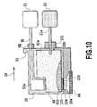
- the carriage In ink refilling, the carriage is first moved in the direction of the arrow 28 to connect the ink intake port 20b and the suction port 53 to the corresponding joints 101 and 102, as shown in FIG. 10. Subsequently, the suction pump 31 performs a suction operation to suck air from the storage ink tank 20 via the gas transmitting member 48 to set the interior of the storage ink tank 20 at negative pressure. The negative pressure in the storage ink tank 20 causes the ink in the main tank 22 to be sucked to the interior of the storage ink tank 20 as shown in FIGS. 11 and 12.
- the negative pressure in the storage ink tank 20 causes the valve 104 to operate in such a way as to close the supplying port 20f, as shown in FIGS. 11 and 12. Accordingly, the ink in the recording head 20a is not sucked to the interior of the storage ink tank 20, and ink meniscus formed at the ink ejecting port in the recording head 20a is not destroyed. Further, air does not enter the recording head 20a or the storage ink tank 20 through the ink ejecting port. This ensures that the ink is sucked from the main tank 22 and supplied to the interior of the storage ink tank 20.
- the ink refilling is automatically stopped because the gas transmitting member 48 does not transmit liquids such as inks therethrough.
- exerting a certain amount or more of negative pressure may destroy the gas transmitting member 48 to eliminate its inherent function of separating a gas and a liquid from each other, thus causing the ink, a liquid, to be also sucked. Consequently, a large amount of ink may be sucked from the storage ink tank 20 to waste the ink, the ink may flow into the suction pump 31 to destroy it, or a waste ink may contaminate the recording apparatus.
- the present invention provides an ink tank which supplies an ink to an ink jet recording head via an ink supplying port, which can supply the ink by introducing negative pressure thereinside, and which has a gas-liquid separating means in a suction port through which the negative pressure required to suck and supply the ink is introduced, the gas-liquid separating means transmitting gases therethrough while not transmitting the gas therethrough, the ink tank being characterized by having a fixed-negative-pressure generating means provided between the gas-liquid separating means and a source of the negative-pressure required to suck and supply the ink, the fixed-negative-pressure generating means preventing a fixed amount or more of negative pressure from being exerted on the gas-liquid separating means.
- This provides an ink tank which is durable enough to be refilled with the ink many times and which prevents the original gas-liquid separating function of the gas transmitting member as a gas-liquid separating means from being destroyed due to excessive negative pressure exerted on the gas transmitting member, thereby achieving an appropriate ink refilling operation and a reliable ink sucking and supplying operation.
- the ink tank of the present invention is also characterized by including as the fixed-negative-pressure generating means, a suction pump having a negative-pressure sensor. This prevents the original gas-liquid separating function of the gas transmitting member as a gas-liquid separating means from being destroyed due to excessive negative pressure exerted on the gas transmitting member, thereby achieving an appropriate ink refilling operation and a reliable ink sucking and supplying operation.
- the ink tank of the present invention is further characterized by including a tube pump as the fixed-negative-pressure generating means. This prevents the original gas-liquid separating function of the gas transmitting member as a gas-liquid separating means from being destroyed due to excessive negative pressure exerted on the gas transmitting member, thereby achieving an appropriate ink refilling operation and a reliable ink sucking and supplying operation.
- the ink tank of the present invention is further characterized by including a diaphragm pump as the fixed-negative-pressure generating means. This prevents the original gas-liquid separating function of the gas transmitting member as a gas-liquid separating means from being destroyed due to excessive negative pressure exerted on the gas transmitting member, thereby achieving an appropriate ink refilling operation and a reliable ink sucking and supplying operation.
- the present invention provides an ink jet recording head installed on an ink tank which supplies an ink to an ink jet recording head via an ink supplying port, which can supply the ink by introducing negative pressure thereinside, and which has a gas-liquid separating means in a suction port through which the negative pressure required to suck and supply the ink is introduced, the gas-liquid separating means transmitting gases therethrough while not transmitting the gas therethrough, the ink jet recording head being characterized by having a fixed-negative-pressure generating means provided between the gas-liquid separating means and a source of the negative-pressure required to suck and supply the ink, the fixed-negative-pressure generating means preventing a fixed amount or more of negative pressure from being exerted on the gas-liquid separating means.
- the ink jet recording head of the present invention is also characterized by including as the fixed-negative-pressure generating means, a suction pump having a negative-pressure sensor. This enables the ink jet recording head to be appropriately produced so as to have a simple configuration, thereby achieving an appropriate ink refilling operation and a reliable ink sucking and supplying operation.
- the ink jet recording head of the present invention is further characterized by including a tube pump as the fixed-negative-pressure generating means. This enables the ink jet recording head to be appropriately produced so as to have a simple configuration, thereby achieving an appropriate ink refilling operation and a reliable ink sucking and supplying operation.
- the ink jet recording head of the present invention is further characterized by having a diaphragm pump as the fixed-negative-pressure generating means. This enables the ink jet recording head to be appropriately produced so as to have a simple configuration.
- the present invention provides an ink jet cartridge having an ink tank installed therein, which supplies an ink to an ink jet recording head via an ink supplying port, which can supply the ink by introducing negative pressure thereinside, and which has a gas-liquid separating means in a suction port through which the negative pressure required to suck and supply the ink is introduced, the gas-liquid separating means transmitting gases therethrough while not transmitting the gas therethrough, the ink jet cartridge being characterized by having a fixed-negative-pressure generating means provided between the gas-liquid separating means and a source of the negative-pressure required to suck and supply the ink, the fixed-negative-pressure generating means preventing a fixed amount or more of negative pressure from being exerted on the gas-liquid separating means.
- the ink jet cartridge of the present invention is also characterized by including as the fixed-negative-pressure generating means, a suction pump having a negative-pressure sensor. This enables the ink jet cartridge to be appropriately produced so as to have a simple configuration, thereby achieving an appropriate ink refilling operation and a reliable ink sucking and supplying operation.
- the ink jet cartridge of the present invention is further characterized by including a tube pump as the fixed-negative-pressure generating means. This enables the ink jet cartridge to be appropriately produced so as to have a simple configuration, thereby achieving an appropriate ink refilling operation and a reliable ink sucking and supplying operation.
- the ink jet cartridge of the present invention is further characterized by including a diaphragm pump as the fixed-negative-pressure generating means. This enables the ink jet cartridge to be appropriately produced so as to have a simple configuration, thereby achieving an appropriate ink refilling operation and a reliable ink sucking and supplying operation.
- the ink jet cartridge of the present invention is further characterized by having a diaphragm pump as the fixed-negative-pressure generating means. This enables the ink jet cartridge to be appropriately produced so as to have a simple configuration.
- the present invention provides an ink jet recording apparatus having an ink tank which supplies an ink to an ink jet recording head via an ink supplying port and which can supply the ink by introducing negative pressure thereinside, the ink jet recording apparatus having a gas-liquid separating means in a suction port through which the negative pressure required to suck and supply the ink is introduced, the gas-liquid separating means transmitting gases therethrough while not transmitting the gas therethrough, the ink jet recording apparatus being characterized by having a fixed-negative-pressure generating means provided between the gas-liquid separating means and a source of the negative-pressure required to suck and supply the ink, the fixed-negative-pressure generating means preventing a fixed amount or more of negative pressure from being exerted on the gas-liquid separating means.
- This provides an ink jet recording apparatus which is durable enough to be refilled with the ink many times and which prevents the original gas-liquid separating function of the gas transmitting member as a gas-liquid separating means from being destroyed due to excessive negative pressure exerted on the gas transmitting member, thereby achieving an appropriate ink refilling operation and a reliable ink sucking and supplying operation.
- the ink jet recording apparatus of the present invention is also characterized by including as the fixed-negative-pressure generating means, a suction pump having a negative-pressure sensor. This serves to achieve an appropriate ink refilling operation and a reliable ink sucking and supplying operation, and enables the ink jet recording apparatus to be appropriately produced so as to have a simple configuration.
- the ink jet recording apparatus of the present invention is further characterized by including a tube pump as the fixed-negative-pressure generating means. This serves to achieve an appropriate ink refilling operation and a reliable ink sucking and supplying operation.
- the ink jet recording apparatus of the present invention is further characterized by having a diaphragm pump as the fixed-negative-pressure generating means. This allows the ink to flow appropriately to achieve stable ink refilling and supplying operations.
- the present invention provides an ink tank, an ink jet recording head, an ink jet cartridge, and an ink jet recording apparatus; the present invention provides an ink tank which supplies an ink to the ink jet recording head via an ink supplying port, which can supply the ink by introducing negative pressure thereinside, and which has a gas-liquid separating means in a suction port through which the negative pressure required to suck and supply the ink is introduced, the gas-liquid separating means transmitting gases therethrough while not transmitting the gas therethrough, wherein the ink tank has a fixed-negative-pressure generating means provided between the gas-liquid separating means and a source of the negative-pressure required to suck and supply the ink, the fixed-negative-pressure generating means comprising a suction pump, a tube pump, a diaphragm pump or the like which has a negative-pressure sensor and preventing a fixed amount or more of negative pressure from being exerted on the gas-liquid separating means.
- This provides a compact and reliable ink jet recording apparatus which is durable enough to be refilled with the ink many times and which prevents the original gas-liquid separating function of the gas transmitting member as a gas-liquid separating means from being destroyed due to excessive negative pressure exerted on the gas transmitting member, thereby achieving an appropriate ink refilling operation and a reliable ink sucking and supplying operation.
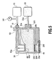
- FIGS. 1 to 6 An integral part of the serial-scan-based ink jet recording apparatus of the present invention will be shown based on FIGS. 1 to 6.
- a storage ink tank 20 acting as a sub-ink tank includes an ink jet recording head capable of ejecting an ink, that is, a recording head 20a and is removably mounted on a carriage (not shown) of the serial-scan-based ink jet recording apparatus.
- the recording head 20a ejects an ink from an ink ejecting port in a nozzle 44 in the storage ink tank 20 based on image information.
- the storage ink tank 20 also has an ink supplying port 20f for supplying the ink from the storage ink tank 20 to the recording head 20a.
- the nozzle 44 includes an ejection energy generating means generating energy required to eject the ink.
- Such an ejection energy generating means may comprise an electrothermal converter for generating thermal energy. Furthermore, the carriage (not shown) is moved by an appropriate movement mechanism in the main scan direction shown by arrows 28 and 35. Further, recorded media are conveyed by a transfer means in a subscan direction crossing the main scan direction.
- an image can sequentially be recorded on the recorded medium by repeating a main scan of the carriage with the recording head 20a and the storage ink tank 20 mounted thereon and a subscan of the recorded medium.
- the storage ink tank 20 has a suction port 53 and an ink intake port 20b formed in a side thereof.
- the suction port 53 is in communication with the interior of the storage ink tank 20 via a suction passage 53a, and a gas transmitting member 48 is provided at the site of the opening of the suction passage 53a in the storage ink tank 20.
- the gas transmitting member 48 has, as a gas-liquid separating means, a function of transmitting gases therethrough while not transmitting inks therethrough.
- the gas transmitting member 48 preferably comprise a thin sheet formed of an ethylene tetrafluorice resin, a similar porous resin material, or the like.
- the storage ink tank 20 has an ink absorber 41a accommodated therein, for sucking and holding the ink.
- a filter 103 and a valve 104 are provided in the supplying port 20f.
- the valve 104 is shaped like a seat and has its proximal end welded to the filter 103.
- the valve 104 functions to open and close the supplying port 20f depending on the internal pressure of the storage ink tank 20.
- the storage ink tank 20 can be connected to a main tank 22 of the recording apparatus main body via a tube 21a by means of a supplying joint 101 that is connectable to the ink intake port 20b.
- the joint 101 and a joint 102 are disposed in the recording apparatus main body so as to lie opposite to the ink intake port 20b and the suction port 53 in the scan direction 35 of the carriage.
- valve 104 is open and the ink is supplied from the storage ink tank 20 to the recording head 20a, as shown in FIG. 1.
- FIGS. 2 to 6 are views useful in explaining an operation of refilling the above described ink tank with the ink.
- the carriage In ink refilling, the carriage is first moved in the direction of the arrow 28 to connect the ink intake port 20b and the suction port 53 to the corresponding joints 101 and 102, as shown in FIG. 2. Subsequently, the suction pump 31 performs a suction operation to suck air from the storage ink tank 20 via the gas transmitting member 48 to set the interior of the storage ink tank 20 at negative pressure. The negative pressure in the storage ink tank 20 causes the ink in the main tank 22 to be sucked to the interior of the storage ink tank 20 as shown in FIGS. 3 and 4.
- the negative pressure in the storage ink tank 20 causes the valve 104 to close the supplying port 20f, as shown in FIGS. 3 and 4. Accordingly, the ink in the recording head 20a is not sucked to the interior of the storage ink tank 20, and ink meniscus formed at the ink ejecting port in the recording head 20a is not destroyed. Further, air does not enter the recording head 20a or the storage ink tank 20 through the ink ejecting port. This ensures that the ink is sucked and supplied to the interior of the storage ink tank 20.
- a negative-pressure sensor 106 is installed in the middle of a conduit 55 located between the suction pump 31 and the joint 102 so that a drive source (not shown) for the suction pump 31 can be turned off once such a preset negative pressure that the gas transmitting member 48 is not destroyed is reached, thus preventing the destruction of the gas transmitting member 48.
- the gas transmitting member 48 comprises Goatex (a trade name) and has a thickness of 30 ⁇ m, and the negative pressure is set at 0.2 atm.
- the negative-pressure sensor 106 comprises, for example, a semiconductor or a diaphragm that is displaced under negative pressure, and the negative-pressure sensor 106 is not limited to the position shown in the figure but may be positioned anywhere between the gas transmission member 48 and the suction pump 31.
- the carriage 19 moves in the direction of the arrow 35 to separate and remove the ink intake port 20b and the suction port 53 from the corresponding joints 101 and 102 to thereby complete the series of refilling operations.
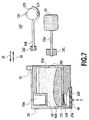
- the negative-pressure sensor detects negative pressure in the suction system to stop the drive source for the suction pump 31, but in this Embodiment 2, a tube pump 107 is used as the suction pump 31 as shown in FIG. 7. That is, a tube 108 is used as the conduit 55, and a roller holder 109 moves rotationally to cause two rollers 110 rotationally moved integrally therewith to squeeze the tube 108. After the roller 110 has passed through, the tube 108 attempts to recover its original state. At this time, negative pressure occurs in the tube 108. The value of the negative pressure is such that the gas transmitting member 48 is not destroyed.
- the tube 108 Since, however, the value of the negative pressure is determined by the recovery force of the tube 108 as described previously, the tube 108 remains collapsed at a certain negative-pressure value, which no longer increases, thereby preventing the gas transmitting member 48 from being destroyed despite the driving of the roller holder 109 by the drive source (not shown).
- the arrangement of the roller 110 at the opposite position prevents the negative pressure in the tube 108 from reaching the atmospheric value to provide an efficient pump form.
- the material of the tube 108 is preferably Tygo (a trade name) of a vinyl chloride or is formed of silicon or the like.
- the driving by the tube pump 107 is turned off once the number of rotations required to fill the empty storage ink tank 20 is reached; this number of rotations is determined by the volume of the storage ink tank 20 and the capacity of the tube pump 107.
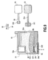
- a diaphragm pump 111 is installed in the conduit 55 as a suction pump.
- a housing 112 has the conduit 55 attached thereto, and at an end of the conduit 55, a valve 113 is integrally mounted on the housing 112.
- a valve 114 is provided outside an aperture in the housing 112 which is located opposite to the valve 113.
- a diaphragm 115 has a conductive diaphragm holder 117 integrally attached thereto, and the tip of a projection 117a of the diaphragm holder 117 is threaded.
- a compression coil spring 118 is installed around an outer periphery of the projection 117a, and a stopper 119 compresses the compression coil spring 118.
- a subhousing 116 has two opposite electric contacts 116a and 116b welded to an aperture in the center thereof and connected to leads 120a and 120b connected to a circuit board.
- the stopper 119 has a pump cam 122 installed thereon and rotating around a shaft 121.
- the pump cam 122 pushes the stopper 119, the diaphragm 115 is displaced downward to open the valve 114, while the valve 113 remains blocked to discharge air in a direction A.
- the stopper 119 is relieved from the pump cam 122, the diaphragm 115 rises to set the interior of the pump at negative pressure to open the valve 113, while blocking the valve 114, so that air is sucked in a direction B from the conduit 55 to the interior of the diaphragm pump.
- the above operation is repeated to suck air via the gas transmitting member 48 to thereby suck the ink to the interior of the storage ink tank 20. Then, when the ink reaches the gas transmitting member 48 and the tank is then filled with the ink, the negative pressure in the diaphragm pump 111 rises rapidly and the diaphragm 115 thus overcomes resistance force from the compression coil spring 118. Accordingly, the diaphragm 115 remains displaced downward, while the pump cam 122 runs idly, thereby making it no longer possible to suck air. Consequently, the negative pressure is hindered from further acting on the gas transmitting member 48, thus preventing the gas transmitting member 48 from being destroyed.
- the value of the negative pressure depends on a set value for the compression coil spring 118. This value can be adjusted by the stopper 119, which is threaded. At this time, control may be provided such that the rotation of the pump cam 122 is stopped when the conduction through the leads 120a and 120b is turned off.
- Suitable materials of the diaphragm 115 include hydrogen nitride butadiene rubber (HNBR), chlorinated butyl rubber, ethylene-propylene-dienta-polymer (EPDM), and the like.
- HNBR hydrogen nitride butadiene rubber
- EPDM ethylene-propylene-dienta-polymer
- thermal energy generated by an electrothermal converter is utilized to effect film boiling in a liquid to form bubbles therein.
- An ink tank (20) has a fixed-negative-pressure generating means (31, 106) between a gas-liquid separating means (48) and a source (31) of negative pressure required to suck and supply the ink, to prevent a fixed amount or more of negative pressure from being exerted on the gas-liquid separating means (48).
- An ink jet recording head (20a) is installed on the ink tank (20).
- An ink jet cartridge is also installed on the ink tank (20).
- An ink jet recording apparatus has an ink tank (20) which supplies an ink to an ink jet recording head (20a) via an ink supplying port (205), a gas-liquid separating means (48) in a suction port (53) transmitting gases therethrough while not transmitting said ink therethrough, and a fixed-negative-pressure generating means (31, 106) between the gas-liquid separating means (48) and a source (31) of the negative pressure.
Landscapes
- Ink Jet (AREA)
Abstract
Description
Claims (16)
- An ink tank which supplies an ink to an ink jet recording head via an ink supplying port, which can supply the ink by introducing negative pressure thereinside, and which has a gas-liquid separating means in a suction port through which the negative pressure required to suck and supply the ink is introduced, said gas-liquid separating means transmitting gases therethrough while not transmitting said ink therethrough, the ink tank being characterized by having:
a fixed-negative-pressure generating means provided between said gas-liquid separating means and a source of the negative pressure required to suck and supply the ink, said fixed-negative-pressure generating means preventing a fixed amount or more of negative pressure from being exerted on said gas-liquid separating means. - The ink tank according to Claim 1, characterized by including as said fixed-negative-pressure generating means, a suction pump having a negative-pressure sensor.
- The ink tank according to Claim 1, characterized by including a tube pump as said fixed-negative-pressure generating means.
- The ink tank according to Claim 1, characterized by including a diaphragm pump as said fixed-negative-pressure generating means.
- An ink jet recording head installed on an ink tank which supplies an ink to an ink jet recording head via an ink supplying port, which can supply the ink by introducing negative pressure thereinside, and which has a gas-liquid separating means in a suction port through which the negative pressure required to suck and supply the ink is introduced, said gas-liquid separating means transmitting gases therethrough while not transmitting said ink therethrough, the ink jet recording head being characterized by having:
a fixed-negative-pressure generating means provided between said gas-liquid separating means and a source of the negative pressure required to suck and supply the ink, said fixed-negative-pressure generating means preventing a fixed amount or more of negative pressure from being exerted on said gas-liquid separating means. - The ink jet recording head according to Claim 5, characterized by including as said fixed-negative-pressure generating means, a suction pump having a negative-pressure sensor.
- The ink jet recording head according to Claim 5, characterized by including a tube pump as said fixed-negative-pressure generating means.
- The ink jet recording head according to Claim 5, characterized by having a diaphragm pump as said fixed-negative-pressure generating means.
- An ink jet cartridge having an ink tank installed therein, which supplies an ink to an ink jet recording head via an ink supplying port, which can supply the ink by introducing negative pressure thereinside, and which has a gas-liquid separating means in a suction port through which the negative pressure required to suck and supply the ink is introduced, said gas-liquid separating means transmitting gases therethrough while not transmitting said ink therethrough, the ink jet cartridge being characterized by having:
a fixed-negative-pressure generating means provided between said gas-liquid separating means and a source of the negative pressure required to suck and supply the ink, said fixed-negative-pressure generating means preventing a fixed amount or more of negative pressure from being exerted on said gas-liquid separating means. - The ink jet cartridge according to Claim 9, characterized by including as said fixed-negative-pressure generating means, a suction pump having a negative-pressure sensor.
- The ink jet cartridge according to Claim 9, characterized by including a tube pump as said fixed-negative-pressure generating means.
- The ink jet cartridge according to Claim 9 characterized by having a diaphragm pump as said fixed-negative-pressure generating means.
- An ink jet recording apparatus having an ink tank which supplies an ink to an ink jet recording head via an ink supplying port and which can supply the ink by introducing negative pressure thereinside, the ink jet recording apparatus having a gas-liquid separating means in a suction port through which the negative pressure required to suck and supply the ink is introduced, said gas-liquid separating means transmitting gases therethrough while not transmitting said ink therethrough, the ink jet recording apparatus being characterized by having:
a fixed-negative-pressure generating means provided between said gas-liquid separating means and a source of the negative pressure required to suck and supply the ink, said fixed-negative-pressure generating means preventing a fixed amount or more of negative pressure from being exerted on said gas-liquid separating means. - The ink jet recording apparatus according to Claim 13, characterized by including as said fixed-negative-pressure generating means, a suction pump having a negative-pressure sensor.
- The ink jet recording apparatus according to Claim 13, characterized by including a tube pump as said fixed-negative-pressure generating means.
- The ink jet recording apparatus according to Claim 13, characterized by having a diaphragm pump as the fixed-negative-pressure generating means.
Applications Claiming Priority (2)
| Application Number | Priority Date | Filing Date | Title |
|---|---|---|---|
| JP2000126598 | 2000-04-26 | ||
| JP2000126598A JP3416614B2 (en) | 2000-04-26 | 2000-04-26 | Ink jet recording device |
Publications (3)
| Publication Number | Publication Date |
|---|---|
| EP1149706A2 true EP1149706A2 (en) | 2001-10-31 |
| EP1149706A3 EP1149706A3 (en) | 2002-07-31 |
| EP1149706B1 EP1149706B1 (en) | 2006-10-11 |
Family
ID=18636352
Family Applications (1)
| Application Number | Title | Priority Date | Filing Date |
|---|---|---|---|
| EP01110244A Expired - Lifetime EP1149706B1 (en) | 2000-04-26 | 2001-04-25 | Ink tank, ink jet recording head, ink jet cartridge, and ink jet recording apparatus |
Country Status (4)
| Country | Link |
|---|---|
| US (1) | US6637872B2 (en) |
| EP (1) | EP1149706B1 (en) |
| JP (1) | JP3416614B2 (en) |
| DE (1) | DE60123697T2 (en) |
Cited By (7)
| Publication number | Priority date | Publication date | Assignee | Title |
|---|---|---|---|---|
| EP1403067A1 (en) * | 2002-09-30 | 2004-03-31 | Canon Kabushiki Kaisha | Ink supply system, ink jet printing apparatus, ink container, ink refilling container and ink jet cartridge |
| EP1502745A1 (en) * | 2003-07-31 | 2005-02-02 | Shinko Electric Industries Co., Ltd. | Inkjet printer |
| EP1502749A1 (en) * | 2003-07-29 | 2005-02-02 | Brother Kogyo Kabushiki Kaisha | Inkjet recording apparatus and ink cartridge |
| WO2005092626A1 (en) * | 2004-03-25 | 2005-10-06 | Sooners Innovation Pte Ltd | Inkjet cartridge refilling assembly and method |
| CN101774304A (en) * | 2010-02-28 | 2010-07-14 | 詹洪明 | Negative pressure generator special for ink supply system of inkjet printer |
| CN101474914B (en) * | 2008-12-01 | 2011-03-30 | 万事达墨水有限公司 | Refilling the Ink System |
| US8926073B2 (en) | 2010-07-15 | 2015-01-06 | Seiko Epson Corporation | Liquid container and liquid ejection system |
Families Citing this family (47)
| Publication number | Priority date | Publication date | Assignee | Title |
|---|---|---|---|---|
| EP1197338A1 (en) | 2000-10-05 | 2002-04-17 | Canon Kabushiki Kaisha | Liquid container and method for disconnecting liquid container |
| US6846072B2 (en) * | 2000-11-29 | 2005-01-25 | Canon Kabushiki Kaisha | Ink, ink-jet ink, ink-tank, ink-jet cartridge, ink supply device, method for introducing ink to ink tank and image recording device |
| JP3787520B2 (en) | 2000-12-28 | 2006-06-21 | キヤノン株式会社 | Structure manufacturing method and manufacturing apparatus therefor |
| JP3787522B2 (en) * | 2001-12-28 | 2006-06-21 | キヤノン株式会社 | Structure, liquid tank, ink jet recording apparatus manufacturing method, and ink jet recording apparatus |
| JP2003200594A (en) * | 2002-01-04 | 2003-07-15 | Canon Inc | Liquid supply device and recording device |
| JP4148498B2 (en) * | 2002-02-15 | 2008-09-10 | キヤノン株式会社 | Liquid jet recording head and liquid jet recording apparatus |
| US6837921B2 (en) * | 2002-03-12 | 2005-01-04 | Canon Kabushiki Kaisha | Ink tank |
| JP2004188641A (en) * | 2002-12-09 | 2004-07-08 | Canon Inc | Inkjet cartridge |
| CN100352657C (en) * | 2003-02-26 | 2007-12-05 | 付刚 | Automatic ink refilling device and method for ink cartridge of ink jet printer |
| JP4218960B2 (en) * | 2004-04-20 | 2009-02-04 | キヤノン株式会社 | Ink container and recording apparatus |
| JP2005305775A (en) * | 2004-04-20 | 2005-11-04 | Canon Inc | Inkjet recording device |
| US7844665B2 (en) | 2004-04-23 | 2010-11-30 | Waratek Pty Ltd. | Modified computer architecture having coordinated deletion of corresponding replicated memory locations among plural computers |
| US20060095483A1 (en) * | 2004-04-23 | 2006-05-04 | Waratek Pty Limited | Modified computer architecture with finalization of objects |
| US7284844B2 (en) * | 2004-07-30 | 2007-10-23 | Hewlett-Packard Development Comapny, L.P. | Air-driven delivery assembly |
| EP1662140B1 (en) | 2004-11-30 | 2014-08-06 | Brother Kogyo Kabushiki Kaisha | Pump, liquid transporting apparatus provided with the same, and liquid moving apparatus |
| JP4522245B2 (en) | 2004-12-09 | 2010-08-11 | キヤノン株式会社 | Liquid container and inkjet recording apparatus |
| US8028299B2 (en) | 2005-04-21 | 2011-09-27 | Waratek Pty, Ltd. | Computer architecture and method of operation for multi-computer distributed processing with finalization of objects |
| US7429101B2 (en) * | 2005-04-22 | 2008-09-30 | Hewlett-Packard Development Company, L.P. | Ink supply with ink/air separator assembly that is isolated from ink until time of use |
| JP4677296B2 (en) * | 2005-06-24 | 2011-04-27 | キヤノン株式会社 | Recording device |
| JP4810933B2 (en) * | 2005-08-31 | 2011-11-09 | ブラザー工業株式会社 | Gas removal device for ink supply mechanism, ink supply mechanism, and inkjet printer |
| JP4878812B2 (en) * | 2005-11-04 | 2012-02-15 | 株式会社リコー | Recording liquid container and image forming apparatus |
| US20070247497A1 (en) * | 2006-04-25 | 2007-10-25 | Lexmark International Inc. | Ink supply systems and methods for inkjet printheads |
| JP4933201B2 (en) * | 2006-09-04 | 2012-05-16 | 富士フイルム株式会社 | Liquid supply method |
| US7918550B2 (en) * | 2007-03-28 | 2011-04-05 | Lexmark International, Inc. | Membrane divided foam for use in an ink jet cartridge |
| EP1997639B1 (en) * | 2007-05-31 | 2010-02-17 | Brother Kogyo Kabushiki Kaisha | Liquid-droplet ejecting apparatus |
| JP5047916B2 (en) * | 2008-09-29 | 2012-10-10 | 株式会社ミマキエンジニアリング | Ink supply device for ink jet printer and reverse flow blocking device |
| JP5483910B2 (en) * | 2009-03-10 | 2014-05-07 | キヤノン株式会社 | Inkjet recording device |
| JP2010208187A (en) * | 2009-03-11 | 2010-09-24 | Seiko Epson Corp | Liquid jetting apparatus |
| JP2010208188A (en) * | 2009-03-11 | 2010-09-24 | Seiko Epson Corp | Method for removing air bubbles |
| US8192000B2 (en) * | 2009-07-17 | 2012-06-05 | Lexmark International, Inc. | Fluid height backpressure system for supplying fluid to a printhead and backpressure device used therein |
| JP2012210726A (en) | 2011-03-30 | 2012-11-01 | Brother Industries Ltd | Ink cartridge |
| JP2012210729A (en) * | 2011-03-30 | 2012-11-01 | Brother Industries Ltd | Ink cartridge |
| GB2492593A (en) * | 2011-07-08 | 2013-01-09 | Inca Digital Printers Ltd | Pressure regulation system |
| JP6098464B2 (en) * | 2013-09-30 | 2017-03-22 | ブラザー工業株式会社 | Liquid ejection device |
| JP6415114B2 (en) | 2014-05-30 | 2018-10-31 | キヤノン株式会社 | Liquid storage unit, liquid discharge apparatus using the same, and method for removing bubbles from liquid storage unit |
| JP6519225B2 (en) * | 2015-02-25 | 2019-05-29 | セイコーエプソン株式会社 | Dummy member and liquid ejecting apparatus |
| JP6579800B2 (en) | 2015-05-25 | 2019-09-25 | キヤノン株式会社 | Inkjet recording device |
| JP6308989B2 (en) | 2015-09-30 | 2018-04-11 | キヤノン株式会社 | Liquid storage container and liquid discharge device |
| JP6723729B2 (en) | 2015-11-17 | 2020-07-15 | キヤノン株式会社 | Liquid storage container and method of manufacturing liquid storage container |
| JP6624905B2 (en) | 2015-11-26 | 2019-12-25 | キヤノン株式会社 | Liquid container and liquid level detector |
| US10391776B2 (en) | 2015-11-30 | 2019-08-27 | Canon Kabushiki Kaisha | Liquid storage container and printing apparatus |
| JP6390730B2 (en) * | 2017-02-23 | 2018-09-19 | ブラザー工業株式会社 | Liquid ejection device |
| JP7282574B2 (en) * | 2019-04-05 | 2023-05-29 | キヤノン株式会社 | Inkjet recording device |
| JP7532055B2 (en) | 2020-03-24 | 2024-08-13 | キヤノン株式会社 | Liquid Supply Unit |
| JP7504641B2 (en) | 2020-03-27 | 2024-06-24 | キヤノン株式会社 | Liquid ejection device |
| JP7520574B2 (en) | 2020-05-22 | 2024-07-23 | キヤノン株式会社 | LIQUID CARTRIDGE AND LIQUID EJECTION DEVICE |
| JP7646317B2 (en) * | 2020-09-28 | 2025-03-17 | キヤノン株式会社 | Liquid container and liquid ejection device |
Family Cites Families (18)
| Publication number | Priority date | Publication date | Assignee | Title |
|---|---|---|---|---|
| US4187511A (en) | 1978-03-20 | 1980-02-05 | Centronics Data Computer Corp. | Method and apparatus for filling the movable reservoir of an inkjet printer |
| JPS6124458A (en) | 1984-07-13 | 1986-02-03 | Nec Corp | Defoaming unit for ink jet printing head |
| US5790158A (en) * | 1992-01-28 | 1998-08-04 | Seiko Epson Corporation | Ink-jet recording apparatus and ink tank cartridge therefor |
| FR2690648B1 (en) * | 1992-04-30 | 1994-07-08 | Imaje | METHOD FOR OPTIMIZING THE OPERATION OF AN INK JET PRINTER AND PRINTER USING SUCH A METHOD. |
| US5489925A (en) * | 1993-05-04 | 1996-02-06 | Markem Corporation | Ink jet printing system |
| WO1995012109A1 (en) | 1993-10-26 | 1995-05-04 | Spectra, Inc. | Ink jet head with vacuum reservoir |
| TW373595U (en) * | 1994-05-25 | 1999-11-01 | Canon Kk | An ink container and an ink jet recording apparatus using the same |
| JP3122323B2 (en) | 1995-01-13 | 2001-01-09 | キヤノン株式会社 | INK TANK AND INK JET RECORDING APPARATUS EQUIPPED WITH IT |
| JPH07329316A (en) | 1994-06-07 | 1995-12-19 | Tec Corp | Head maintenance apparatus for ink jet printer |
| JP3521296B2 (en) | 1995-07-07 | 2004-04-19 | ブラザー工業株式会社 | Ink injection method and ink injection apparatus |
| US5663754A (en) | 1995-09-05 | 1997-09-02 | Xerox Corporation | Method and apparatus for refilling ink jet cartridges |
| US5801735A (en) * | 1995-09-05 | 1998-09-01 | Xerox Corporation | Automated system for refilling ink jet cartridges |
| JP3684022B2 (en) * | 1996-04-25 | 2005-08-17 | キヤノン株式会社 | Liquid replenishment method, liquid discharge recording apparatus, and ink tank used as a main tank of the liquid discharge recording apparatus |
| US6302516B1 (en) * | 1997-01-14 | 2001-10-16 | Markem Corporation | Ink supply system for ink jet printhead |
| US5975689A (en) | 1997-02-03 | 1999-11-02 | Hewlett-Packard Co. | Air purge apparatus for inkjet print cartridges |
| JP3478116B2 (en) | 1998-02-25 | 2003-12-15 | セイコーエプソン株式会社 | Ink jet recording apparatus, method of using the same, and ink tank thereof |
| US5967045A (en) | 1998-10-20 | 1999-10-19 | Imation Corp. | Ink delivery pressure control |
| CA2310181C (en) * | 1999-05-31 | 2004-06-22 | Canon Kabushiki Kaisha | Ink tank, ink-jet cartridge, ink-supplying apparatus, ink-jet printing apparatus and method for supplying ink |
-
2000
- 2000-04-26 JP JP2000126598A patent/JP3416614B2/en not_active Expired - Fee Related
-
2001
- 2001-04-24 US US09/840,165 patent/US6637872B2/en not_active Expired - Fee Related
- 2001-04-25 EP EP01110244A patent/EP1149706B1/en not_active Expired - Lifetime
- 2001-04-25 DE DE60123697T patent/DE60123697T2/en not_active Expired - Lifetime
Cited By (14)
| Publication number | Priority date | Publication date | Assignee | Title |
|---|---|---|---|---|
| US6969161B2 (en) | 2002-09-30 | 2005-11-29 | Canon Kabushiki Kaisha | Ink supply system, ink jet printing apparatus, ink container, ink refilling container and ink jet cartridge |
| EP1403067A1 (en) * | 2002-09-30 | 2004-03-31 | Canon Kabushiki Kaisha | Ink supply system, ink jet printing apparatus, ink container, ink refilling container and ink jet cartridge |
| EP1502749A1 (en) * | 2003-07-29 | 2005-02-02 | Brother Kogyo Kabushiki Kaisha | Inkjet recording apparatus and ink cartridge |
| EP1502745A1 (en) * | 2003-07-31 | 2005-02-02 | Shinko Electric Industries Co., Ltd. | Inkjet printer |
| US7524025B2 (en) | 2003-07-31 | 2009-04-28 | Shinko Electric Industries Co., Ltd. | Inkjet printer |
| WO2005092626A1 (en) * | 2004-03-25 | 2005-10-06 | Sooners Innovation Pte Ltd | Inkjet cartridge refilling assembly and method |
| CN101474914B (en) * | 2008-12-01 | 2011-03-30 | 万事达墨水有限公司 | Refilling the Ink System |
| CN101774304A (en) * | 2010-02-28 | 2010-07-14 | 詹洪明 | Negative pressure generator special for ink supply system of inkjet printer |
| CN101774304B (en) * | 2010-02-28 | 2011-12-21 | 詹洪明 | Negative pressure generator special for ink supply system of inkjet printer |
| US8926073B2 (en) | 2010-07-15 | 2015-01-06 | Seiko Epson Corporation | Liquid container and liquid ejection system |
| EP2479034A4 (en) * | 2010-07-15 | 2015-04-29 | Seiko Epson Corp | LIQUID CONTAINER AND LIQUID FLUID SYSTEM |
| US9358795B2 (en) | 2010-07-15 | 2016-06-07 | Seiko Epson Corporation | Liquid container and liquid ejection system |
| US9505223B2 (en) | 2010-07-15 | 2016-11-29 | Seiko Epson Corporation | Liquid container and liquid ejection system |
| US9878551B2 (en) | 2010-07-15 | 2018-01-30 | Seiko Epson Corporation | Liquid container and liquid ejection system |
Also Published As
| Publication number | Publication date |
|---|---|
| DE60123697D1 (en) | 2006-11-23 |
| EP1149706B1 (en) | 2006-10-11 |
| US20010045976A1 (en) | 2001-11-29 |
| JP2001310477A (en) | 2001-11-06 |
| EP1149706A3 (en) | 2002-07-31 |
| US6637872B2 (en) | 2003-10-28 |
| JP3416614B2 (en) | 2003-06-16 |
| DE60123697T2 (en) | 2007-08-30 |
Similar Documents
| Publication | Publication Date | Title |
|---|---|---|
| EP1149706B1 (en) | Ink tank, ink jet recording head, ink jet cartridge, and ink jet recording apparatus | |
| US6474797B2 (en) | Ink supply system and ink-jet recording apparatus | |
| US6629758B2 (en) | Joint device, ink jet recording apparatus having the same, and ink supplying device and method | |
| US6799840B2 (en) | Ink supply mechanism and inkjet recording apparatus including the ink supply mechanism | |
| JP4841467B2 (en) | Image forming apparatus | |
| JPH04211964A (en) | Suction recovery device and inkjet recording device equipped with the device | |
| JP2015044379A (en) | Liquid discharge device and control method of the same | |
| JP3907364B2 (en) | Inkjet recording device | |
| JP2004082578A (en) | Capping mechanism and ink jet recording apparatus | |
| JPH11320901A (en) | Ink jet recording device | |
| JP2000301732A (en) | Ink jet recording device | |
| US9669642B2 (en) | Ink jet recording apparatus and pre-transportation processing method for the apparatus | |
| JPH04235058A (en) | inkjet recording device | |
| JP2001310487A (en) | Recording head function maintaining device and ink jet recording device using the same | |
| JP2001253093A (en) | Ink jet recording device | |
| JP3062366B2 (en) | Ink jet recording device | |
| JP4602116B2 (en) | Ink jet recording apparatus, tube pump, and liquid feeding method | |
| JP5228885B2 (en) | Tube pump and image forming apparatus | |
| JP2022111069A (en) | Liquid discharge device and method for cleaning recording head | |
| JP2004345316A (en) | Image formation device and ink cartridge | |
| JP2838240B2 (en) | Ink jet recording device | |
| JP3461282B2 (en) | Liquid ejection recording apparatus and liquid supply method thereof | |
| JP7463200B2 (en) | Liquid ejection device | |
| JP3002057B2 (en) | Ink jet recording device | |
| JP2814318B2 (en) | Ink jet recording device |
Legal Events
| Date | Code | Title | Description |
|---|---|---|---|
| PUAI | Public reference made under article 153(3) epc to a published international application that has entered the european phase |
Free format text: ORIGINAL CODE: 0009012 |
|
| AK | Designated contracting states |
Kind code of ref document: A2 Designated state(s): AT BE CH CY DE DK ES FI FR GB GR IE IT LI LU MC NL PT SE TR |
|
| AX | Request for extension of the european patent |
Free format text: AL;LT;LV;MK;RO;SI |
|
| PUAL | Search report despatched |
Free format text: ORIGINAL CODE: 0009013 |
|
| AK | Designated contracting states |
Kind code of ref document: A3 Designated state(s): AT BE CH CY DE DK ES FI FR GB GR IE IT LI LU MC NL PT SE TR |
|
| AX | Request for extension of the european patent |
Free format text: AL;LT;LV;MK;RO;SI |
|
| 17P | Request for examination filed |
Effective date: 20021211 |
|
| AKX | Designation fees paid |
Designated state(s): DE ES FR GB IT NL |
|
| 17Q | First examination report despatched |
Effective date: 20030331 |
|
| GRAP | Despatch of communication of intention to grant a patent |
Free format text: ORIGINAL CODE: EPIDOSNIGR1 |
|
| GRAS | Grant fee paid |
Free format text: ORIGINAL CODE: EPIDOSNIGR3 |
|
| GRAA | (expected) grant |
Free format text: ORIGINAL CODE: 0009210 |
|
| AK | Designated contracting states |
Kind code of ref document: B1 Designated state(s): DE ES FR GB IT NL |
|
| PG25 | Lapsed in a contracting state [announced via postgrant information from national office to epo] |
Ref country code: IT Free format text: LAPSE BECAUSE OF FAILURE TO SUBMIT A TRANSLATION OF THE DESCRIPTION OR TO PAY THE FEE WITHIN THE PRESCRIBED TIME-LIMIT;WARNING: LAPSES OF ITALIAN PATENTS WITH EFFECTIVE DATE BEFORE 2007 MAY HAVE OCCURRED AT ANY TIME BEFORE 2007. THE CORRECT EFFECTIVE DATE MAY BE DIFFERENT FROM THE ONE RECORDED. Effective date: 20061011 Ref country code: NL Free format text: LAPSE BECAUSE OF FAILURE TO SUBMIT A TRANSLATION OF THE DESCRIPTION OR TO PAY THE FEE WITHIN THE PRESCRIBED TIME-LIMIT Effective date: 20061011 |
|
| REG | Reference to a national code |
Ref country code: GB Ref legal event code: FG4D |
|
| REF | Corresponds to: |
Ref document number: 60123697 Country of ref document: DE Date of ref document: 20061123 Kind code of ref document: P |
|
| PG25 | Lapsed in a contracting state [announced via postgrant information from national office to epo] |
Ref country code: ES Free format text: LAPSE BECAUSE OF FAILURE TO SUBMIT A TRANSLATION OF THE DESCRIPTION OR TO PAY THE FEE WITHIN THE PRESCRIBED TIME-LIMIT Effective date: 20070122 |
|
| NLV1 | Nl: lapsed or annulled due to failure to fulfill the requirements of art. 29p and 29m of the patents act | ||
| EN | Fr: translation not filed | ||
| PLBE | No opposition filed within time limit |
Free format text: ORIGINAL CODE: 0009261 |
|
| STAA | Information on the status of an ep patent application or granted ep patent |
Free format text: STATUS: NO OPPOSITION FILED WITHIN TIME LIMIT |
|
| 26N | No opposition filed |
Effective date: 20070712 |
|
| PG25 | Lapsed in a contracting state [announced via postgrant information from national office to epo] |
Ref country code: FR Free format text: LAPSE BECAUSE OF FAILURE TO SUBMIT A TRANSLATION OF THE DESCRIPTION OR TO PAY THE FEE WITHIN THE PRESCRIBED TIME-LIMIT Effective date: 20070601 |
|
| PG25 | Lapsed in a contracting state [announced via postgrant information from national office to epo] |
Ref country code: FR Free format text: LAPSE BECAUSE OF FAILURE TO SUBMIT A TRANSLATION OF THE DESCRIPTION OR TO PAY THE FEE WITHIN THE PRESCRIBED TIME-LIMIT Effective date: 20061011 |
|
| PGFP | Annual fee paid to national office [announced via postgrant information from national office to epo] |
Ref country code: GB Payment date: 20140414 Year of fee payment: 14 |
|
| PGFP | Annual fee paid to national office [announced via postgrant information from national office to epo] |
Ref country code: DE Payment date: 20140430 Year of fee payment: 14 |
|
| REG | Reference to a national code |
Ref country code: DE Ref legal event code: R119 Ref document number: 60123697 Country of ref document: DE |
|
| GBPC | Gb: european patent ceased through non-payment of renewal fee |
Effective date: 20150425 |
|
| PG25 | Lapsed in a contracting state [announced via postgrant information from national office to epo] |
Ref country code: DE Free format text: LAPSE BECAUSE OF NON-PAYMENT OF DUE FEES Effective date: 20151103 Ref country code: GB Free format text: LAPSE BECAUSE OF NON-PAYMENT OF DUE FEES Effective date: 20150425 |