EP1149682A2 - Injection mechanism of injection molding machine - Google Patents
Injection mechanism of injection molding machine Download PDFInfo
- Publication number
- EP1149682A2 EP1149682A2 EP01303719A EP01303719A EP1149682A2 EP 1149682 A2 EP1149682 A2 EP 1149682A2 EP 01303719 A EP01303719 A EP 01303719A EP 01303719 A EP01303719 A EP 01303719A EP 1149682 A2 EP1149682 A2 EP 1149682A2
- Authority
- EP
- European Patent Office
- Prior art keywords
- section
- molding machine
- injection
- linear motor
- injection molding
- Prior art date
- Legal status (The legal status is an assumption and is not a legal conclusion. Google has not performed a legal analysis and makes no representation as to the accuracy of the status listed.)
- Granted
Links
Images


Classifications
-
- B—PERFORMING OPERATIONS; TRANSPORTING
- B29—WORKING OF PLASTICS; WORKING OF SUBSTANCES IN A PLASTIC STATE IN GENERAL
- B29C—SHAPING OR JOINING OF PLASTICS; SHAPING OF MATERIAL IN A PLASTIC STATE, NOT OTHERWISE PROVIDED FOR; AFTER-TREATMENT OF THE SHAPED PRODUCTS, e.g. REPAIRING
- B29C45/00—Injection moulding, i.e. forcing the required volume of moulding material through a nozzle into a closed mould; Apparatus therefor
- B29C45/17—Component parts, details or accessories; Auxiliary operations
- B29C45/46—Means for plasticising or homogenising the moulding material or forcing it into the mould
- B29C45/47—Means for plasticising or homogenising the moulding material or forcing it into the mould using screws
- B29C45/50—Axially movable screw
- B29C45/5008—Drive means therefor
-
- B—PERFORMING OPERATIONS; TRANSPORTING
- B29—WORKING OF PLASTICS; WORKING OF SUBSTANCES IN A PLASTIC STATE IN GENERAL
- B29C—SHAPING OR JOINING OF PLASTICS; SHAPING OF MATERIAL IN A PLASTIC STATE, NOT OTHERWISE PROVIDED FOR; AFTER-TREATMENT OF THE SHAPED PRODUCTS, e.g. REPAIRING
- B29C45/00—Injection moulding, i.e. forcing the required volume of moulding material through a nozzle into a closed mould; Apparatus therefor
- B29C45/17—Component parts, details or accessories; Auxiliary operations
- B29C2045/1784—Component parts, details or accessories not otherwise provided for; Auxiliary operations not otherwise provided for
- B29C2045/1792—Machine parts driven by an electric motor, e.g. electric servomotor
- B29C2045/1793—Machine parts driven by an electric motor, e.g. electric servomotor by an electric linear motor
-
- B—PERFORMING OPERATIONS; TRANSPORTING
- B29—WORKING OF PLASTICS; WORKING OF SUBSTANCES IN A PLASTIC STATE IN GENERAL
- B29C—SHAPING OR JOINING OF PLASTICS; SHAPING OF MATERIAL IN A PLASTIC STATE, NOT OTHERWISE PROVIDED FOR; AFTER-TREATMENT OF THE SHAPED PRODUCTS, e.g. REPAIRING
- B29C45/00—Injection moulding, i.e. forcing the required volume of moulding material through a nozzle into a closed mould; Apparatus therefor
- B29C45/17—Component parts, details or accessories; Auxiliary operations
- B29C45/46—Means for plasticising or homogenising the moulding material or forcing it into the mould
- B29C45/47—Means for plasticising or homogenising the moulding material or forcing it into the mould using screws
- B29C45/50—Axially movable screw
- B29C45/5008—Drive means therefor
- B29C2045/5032—Drive means therefor using means for detecting injection or back pressures
-
- B—PERFORMING OPERATIONS; TRANSPORTING
- B29—WORKING OF PLASTICS; WORKING OF SUBSTANCES IN A PLASTIC STATE IN GENERAL
- B29C—SHAPING OR JOINING OF PLASTICS; SHAPING OF MATERIAL IN A PLASTIC STATE, NOT OTHERWISE PROVIDED FOR; AFTER-TREATMENT OF THE SHAPED PRODUCTS, e.g. REPAIRING
- B29C45/00—Injection moulding, i.e. forcing the required volume of moulding material through a nozzle into a closed mould; Apparatus therefor
- B29C45/17—Component parts, details or accessories; Auxiliary operations
- B29C45/46—Means for plasticising or homogenising the moulding material or forcing it into the mould
- B29C45/47—Means for plasticising or homogenising the moulding material or forcing it into the mould using screws
- B29C45/50—Axially movable screw
- B29C45/5008—Drive means therefor
- B29C2045/5032—Drive means therefor using means for detecting injection or back pressures
- B29C2045/5036—Drive means therefor using means for detecting injection or back pressures back pressure obtaining means
Definitions
- the present invention relates to an injection mechanism of an injection molding machine and particularly relates to an injection mechanism of an injection molding machine using a linear motor as a driving source of the injection mechanism.
- An injection mechanism for driving an injection screw of an injection molding machine in axial direction using a motor is already well known.
- a mechanism for driving this injection screw in the axial direction using a linear motor is also well known by, for example, Japanese Patent Application Laid-Open Nos. 11-58468 and 63-1516 and the like.
- the linear motor is incorporated integrally into the injection mechanism. Due to this, it is disadvantageously difficult to replace or adjust the linear motor.
- the linear motor is constituted such that a very small gap is formed between a linear motor movable section (or a needle) making a linearly movement and a linear motor fixed section (or a stator) to thereby allow the movable section to move relatively to the fixed section.
- the magnitude of this gap influences motor performance. If the linear motor gets out of order and it is necessary to replace it with another linear motor, the replacement operation is difficult to carry out because of the fact that the linear motor is incorporated into the injection mechanism. Further, the adjustment or the like of the gap between the fixed section and the movable section stated above is disadvantageously difficult to make.
- an injection mechanism using a linear motor is constituted so that the fixed section of the linear motor extending in an axial direction and facing the movable section of the linear motor linked to the screw shaft and extending in the axial direction is arranged and that a plurality of pairs constituted of an outer frame into which the fixed section is fixedly attached are combined to surround the screw shaft.
- the linear motor movable section is constituted of a polygonal prism having a plurality of pairs of planes parallel to each other.
- the movable section is linked to an injection screw.
- the electrical elements of the linear motor are arranged on these pairs of two parallel planes, respectively.
- the linear motor fixed section is fixedly attached to the outer frame so that the electrical elements of the fixed section face the electrical elements of the linear motor movable section, respectively.
- the linear motor fixed section has a structure of being detachably attached to the outer frame so that the electrical elements of the fixed section face the electrical elements of the linear motor movable section, respectively.
- a hole section is provided in the outer frame, a lid closing the hole section is used as the linear motor fixed section and the electrical elements of the linear motor fixed section are fixedly attached to the inside of the lid.
- FIG. 1 is a partially cross-sectional view of the principal parts of an injection mechanism in one embodiment according to the present invention.
- a cylinder 2 is attached to a front plate 5.
- a nozzle 1 is attached to the tip end of the cylinder 2.
- An injection screw 3 is inserted into the cylinder 2.
- the injection screw 3 mixes and melts a resin material inputted from a hopper 4 and injects the resultant resin material into a die which is not shown.
- the rear end shaft of the screw 3 is rotatably but axially immovably attached to a moving plate 6.
- the screw 3 has a structure in which this rear end shaft is linked to a measuring shaft 14 to be described later and in which the screw 3 rotates in response to the rotation of the measuring shaft 14 to be described later.
- a linear motor movable section 8 constituting the linear motor is fixed to the moving plate 6 through a load cell 7.
- the linear motor movable section 8 comprises a polygonal prism having a plurality of pairs of planes parallel to each other.
- the movable section 8 comprises a tetragonal prism having a rectangular cross section as shown in FIG. 2.
- FIG. 2 is a cross-sectional view showing that the linear motor section shown in FIG. 1 is cut at the center.
- four magnets 9a, 9b, 9c and 9d which are one of the electrical constituent elements of the linear motor are arranged on the four surfaces of the linear motor movable section 8 comprising a tetragonal prism, respectively, which surfaces are parallel to the axial line of the screw 3.
- an outer frame 10 constituting the linear motor is fixedly attached to the front plate 5. Holes are formed in the outer frame 10 in regions facing the respective surfaces of the linear motor movable section 8 (or the respective planes of the polygonal prism), respectively and the linear motor fixed section is provided to face the linear motor movable section 8.
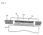
- the outer frame 10 in this embodiment comprises a bottom frame 10a, side frames 10b and 10d and a top frame 10c. Hole sections 11a to 11d are provided in the respective frames 10a to 10d. Linear motor fixed sections 12a to 12d are detachably attached to the frames 10a to 10d to serve as lids of the hole sections 11a to 11d, respectively.
- the linear motor fixed sections 12b, 12c and 12d attached to the both side frames 10b, 10d and the top frame 10c have outside portions formed into flanges, respectively, which flange portions are fixed to the respective frames 10b, 10d and 10c by bolts or the like.
- the linear motor fixed section 12a attached to the bottom frame 10a is formed to be flush with the outer surface of the bottom frame 10a and fixed to the bottom frame 10a at a position at which the fixed section 12a does not have an effect on a nozzle touch driving mechanism, since the nozzle touch driving mechanism for moving the injection mechanism to make the nozzle 1 touch the die is arranged below the bottom frame 10a, as shown in FIG. 3 to be described later.
- Coils 13a to 13d serving as electrical constituent elements of the linear motor fixed sections are provided on the respective linear motor fixed sections 12a to 12d so that the coils face the respective magnets 9a to 9d.
- the magnets 9a to 9d of the linear motor movable section 8 and the coils 13a to 13d of the linear motor fixed sections 12a to 12d face one another with small gaps formed therebetween, respectively. Since the characteristics of the linear motor varies according to the magnitudes of the gaps, it is necessary to adjust the gaps.
- the linear motor fixed sections 12a to 12d are attached to the respective outer frames 10a to 10d.
- adjustment members such as shims between the linear motor fixed sections 12a to 12d and the frames 10a to 10d and fixing the adjustment members with bolts, respectively.
- the linear motor movable section 8 is held by linear guides 22 and 22 (see FIG. 2) provided on the bottom frame 10a so as to be linearly movable in the axial direction of the screw 8.
- the linear motor movable section 8 also has a penetrating hole 15 provided at the center thereof, into which hole the measuring shaft 14 is inserted.
- the measuring shaft 14 linked to the shaft of the screw 3 passes through this penetrating hole 15, protrudes from the rear end portion of the linear motor movable section 8, further passes through the frame 10e on the rear end side of the outer frame 10 and is supported by a motor attachment plate 21 fixedly attached to the rear end frame 10e.
- the measuring shaft 14 is formed with a spline groove 16 in the rear end portion and a pulley 17 is coupled to this spline groove 16.
- a screw rotation motor 18 for rotating the screw 3 to thereby mix, melt and measure a resin is attached to the motor attachment plate 21 attached to the rear end frame 10e of the outer frame 10.
- a belt 20 such as a timing belt is thrown between the pulley 19 fixed to the output shaft of this motor 18 and the pulley 17 spline-linked to the measuring shat 14.
- FIG. 3 shows a state in which this injection mechanism is attached to the base of an injection molding machine and in which the measuring shaft 14, the rear end-side frame 10e and the screw rotation motor 18 have been detached.
- the outer frame 10 of the injection mechanism is attached onto a mounting member 32.
- the mounting member 32 is attached by linear guides 31 provided on the base 30 of the injection molding machine so as to be linearly movable in a direction either toward or away from a fixed platen 34 to which the die is attached.
- a motor 33 drives the injection mechanism to make the nozzle touch the die. Namely, by driving the mounting member 32, the outer frame 10 (i.e., injection mechanism) attached to the mounting member 32 is moved forward and backward and the nozzle 1 is press-contacted with the die attached to the fixed platen 34 or detached from the die.
- the outer frame 10 i.e., injection mechanism
- the injection mechanism in this embodiment is constituted as stated above. Pairs of the magnets 9a to 9d provided on the respective surfaces of the linear motor movable section 8 and the coils 13a to 13d provided on the respective linear motor fixed section facing the magnets 9a to 9d, constitute linear motors, respectively. That is to say, the magnet 9a and the coil 13a, the magnet 9b and the coil 13b, the magnet 9c and the coil 13c and the magnet 9d and the coil 13d constitute linear motors, respectively. This follows that four linear motors are applied to one linear motor movable section 8, thereby making it possible to generate a great force.
- the pair of the magnet 9a and the coil 13a and that of the magnet 9c and the coil 13c constitute the respective linear motors on the surfaces parallel to each other. Since the coils 13a and 13c are located in directions in which both the coils face each other, forces repelling the linear motor movable section 8 are cancelled each other. Also, the pair of magnet 9b and the coil 13b and that of the magnet 9d and the coil 13d constitute the respective linear motors on the surfaces parallel to each other. Since the coils 13b and 13d are located in directions in which the both coils face each other, forces repelling the linear motor movable section 8 are cancelled each other. As a result, no excessive load is not exerted on the linear guides 22 guiding the linear motor movable section 8.
- a linear motor movable section is constituted of a polygonal prism having a plurality of pairs of surfaces parallel to each other, e.g., a polygonal prism having a regular hexagonal cross section
- six linear motors can be provided and three pairs of linear motors each of which pair are arranged on the surfaces of the linear motor movable section parallel to each other, thereby making it possible to cancel forces acting on a perpendicular direction to the direction of the screw shaft each other.
- the cross section of the polygonal prism should not necessarily be a regular polygonal shape and a linear motor movable section can be constituted of a polygonal prism having a plurality of pairs of surfaces parallel to each other.
- linear motors comprising the pair of the magnet 9a and the coil 13a, that of the magnet 9b and the coil 13b, that of the magnet 9c and the coil 13c and that of the magnet 9d and the coil 13d, respectively are driven synchronously with one another and the linear motor movable section 8 is guided by the linear guides 22 to thereby drive the movable section 8 in left direction in FIG. 1.
- the moving plate 6 fixedly attached to the linear motor movable section 8 through the load cell 7 and the screw 3 attached rotatably and axially immovably to the moving plate 6 move linearly together with the linear motor movable section 8 and the molten resin stored in the cylinder 2 is injected.
- the screw rotation motor 18 is driven, the measuring shaft 16 is rotated through the pulley 19, the belt 20 and the pulley 17 and the screw 3 linked to the measuring shaft 16 is rotated, thereby mixing and melting the resin.
- back pressure is applied to the resin by driving the four linear motors stated above. Since the back pressure is low, only a pair of upper and lower linear motors or a pair of left and right linear motors may be driven synchronously with each other.
- the hole sections 11a to 11d are provided in the outer frame 10 and the linear motor fixed sections 12a to 12d are fixedly attached to the hole sections 11a to 11d as lids, respectively.
- linear motor fixed sections may be provided on the outer frame 10 itself.
- coils 13a to 13d may be directly arranged on the bottom frame 10a, the side frame 10b, the top frame 10c and the side frame 10d, respectively. In the latter case, however, gap adjustment disadvantageously becomes more difficult than that in the above-stated embodiment.
- the magnitude of the injection mechanism can be made small by allowing the magnets 9 and the coils 13 to face one another within the thickness of the outer frame 10.
- the electrical constituent elements of the linear motor movable section are magnets and those of the linear motor fixed sections are coils.
- the constituent elements of the movable section and the fixed sections may be reversed. That is, the electrical constituent elements of the fixed sections may be magnets and those of the movable section may be coils. It is also possible to provide linear motors which do not use magnets.
- the present invention it is possible to reduce a dangerous operation due to the magnetic force of the linear motor at the time of replacing or repairing the linear motor and to easily adjust gaps between the magnets and the coils of the linear motor.
Landscapes
- Engineering & Computer Science (AREA)
- Manufacturing & Machinery (AREA)
- Mechanical Engineering (AREA)
- Injection Moulding Of Plastics Or The Like (AREA)
Abstract
Description
Claims (11)
- An injection mechanism of an injection molding machine using a linear motor as a driving source for driving an injection screw shaft in the axial direction, whereinthe linear motor comprises:a movable section linked to the injection screw shaft and extending in the axial direction;an outer frame; anda fixed section fixedly attached to the outer frame and extending in the axial direction while facing the movable section, whereina plurality of the linear motors each constituted of the movable section, the outer frame and the fixed section are arranged to surround the screw shaft.
- An injection mechanism of an injection molding machine according to claim 1, whereinthe movable section of each of the linear motors comprises a polygonal prism having a plurality of pairs of planes parallel to each other, and electrical elements of each of the linear motors are provided on the two planes parallel to each other, respectively; andthe fixed section of each of the linear motors is fixedly attached to the outer frame so that electrical elements of the fixed section face the electrical elements of the movable section of each of the linear motors, respectively.
- An injection mechanism of an injection molding machine according to claim 2, wherein the movable section of each of the linear motors is constituted of a prism having a rectangular cross section, and electrical elements of the linear motors are provided on four planes of the prism, respectively. respectively.
- An injection mechanism of an injection molding machine according to claim 1, 2 or 3, wherein the fixed section of each of the linear motors is detachably attached to the outer frame so that electrical elements of the fixed section face electrical elements of the movable section of each of the linear motors, respectively.
- An injection mechanism of an injection molding machine according to claim 1, 2 or 3, wherein a hole section is provided in the outer frame, the fixed section of each of the linear motors is constituted of a lid closing the hole section, and electrical elements of the fixed section of each of the linear motors are fixedly attached to an inside of the lid.
- An injection mechanism of an injection molding machine according to any preceding claim, wherein one end of the screw shaft is attached to a moving plate constituting the injection molding machine such that it can rotate but cannot move linearly, and the movable section of each of the linear motors is fixed to the moving plate.
- An injection mechanism of an injection molding machine according to claim 6, wherein the movable section of each of the linear motors is fixed to the moving plate through a load cell.
- An injection mechanism of an injection molding machine according to any preceding claim, wherein a cylinder for containing inside the injection screw shaft is attached to a front plate constituting the injection molding machine, the outer frame constituting the linear motor is fixedly attached to the front plate.
- An injection mechanism of an injection molding machine according to any preceding claim, further comprising gap adjustment means for adjusting a gap between the outer frame and the fixed section, the outer frame and the fixed section constituting one linear motor.
- An injection mechanism of an injection molding machine according to any preceding claim, wherein a linear guide for linearly moving the movable section is formed on one constituent member of the outer frame.
- An injection mechanism of an injection molding machine according to any preceding claim, wherein a measuring shaft is linked to one end of the screw shaft, and the measuring shaft passes through a penetrating hole provided in a center of the movable section.
Applications Claiming Priority (2)
| Application Number | Priority Date | Filing Date | Title |
|---|---|---|---|
| JP2000121984 | 2000-04-24 | ||
| JP2000121984A JP3437143B2 (en) | 2000-04-24 | 2000-04-24 | Injection mechanism of injection molding machine |
Publications (3)
| Publication Number | Publication Date |
|---|---|
| EP1149682A2 true EP1149682A2 (en) | 2001-10-31 |
| EP1149682A3 EP1149682A3 (en) | 2002-05-29 |
| EP1149682B1 EP1149682B1 (en) | 2004-08-11 |
Family
ID=18632527
Family Applications (1)
| Application Number | Title | Priority Date | Filing Date |
|---|---|---|---|
| EP01303719A Expired - Lifetime EP1149682B1 (en) | 2000-04-24 | 2001-04-24 | Injection mechanism of injection molding machine |
Country Status (4)
| Country | Link |
|---|---|
| US (1) | US6793477B2 (en) |
| EP (1) | EP1149682B1 (en) |
| JP (1) | JP3437143B2 (en) |
| DE (1) | DE60104762T2 (en) |
Cited By (4)
| Publication number | Priority date | Publication date | Assignee | Title |
|---|---|---|---|---|
| WO2002045939A1 (en) * | 2000-12-04 | 2002-06-13 | Mannesmann Plastics Machinery Gmbh | Injection unit for an injection moulding machine |
| EP1607205A4 (en) * | 2003-03-04 | 2007-05-23 | Sumitomo Heavy Industries | Injection molding machine driving device, injection device and mold clamping device |
| EP1418037A4 (en) * | 2001-08-17 | 2009-06-03 | Sumitomo Heavy Industries | Injection device and injection method |
| CN100584572C (en) * | 2003-03-04 | 2010-01-27 | 住友重机械工业株式会社 | Drive device for injection molding machine and injection device |
Families Citing this family (8)
| Publication number | Priority date | Publication date | Assignee | Title |
|---|---|---|---|---|
| US6517336B1 (en) * | 1998-06-16 | 2003-02-11 | Sumitomo Heavy Industries, Ltd. | Injection molding machine having coaxial injection motor and transmission shaft |
| JP2004001279A (en) * | 2002-05-31 | 2004-01-08 | Toshiba Mach Co Ltd | Injection molding apparatus |
| JP2004358902A (en) * | 2003-06-06 | 2004-12-24 | Fanuc Ltd | Injection mechanism of injection molding machine |
| US20070296281A1 (en) * | 2006-06-07 | 2007-12-27 | Husky Injection Molding Systems Ltd. | Electrical motor |
| US20070296121A1 (en) * | 2006-06-07 | 2007-12-27 | Husky Injection Molding Systems Ltd. | Molding-system drive |
| US20080042322A1 (en) * | 2006-08-15 | 2008-02-21 | Husky Injection Molding Systems Ltd. | Platen-stroke actuator of molding system, amongst other things |
| DE102008037102B4 (en) * | 2008-08-08 | 2010-07-08 | Sumitomo (Shi) Demag Plastics Machinery Gmbh | Injection unit for an injection molding machine and method for operating such an injection unit |
| JP6339648B2 (en) * | 2016-11-22 | 2018-06-06 | ファナック株式会社 | Injection device and shaft center position adjusting method |
Family Cites Families (11)
| Publication number | Priority date | Publication date | Assignee | Title |
|---|---|---|---|---|
| JPS6225022A (en) | 1985-07-25 | 1987-02-03 | Toshiba Mach Co Ltd | Injection molding machine |
| JPS62173137A (en) | 1986-01-28 | 1987-07-30 | Hiroshi Teramachi | Rectilinear guide apparatus |
| JPS6360720A (en) | 1986-09-02 | 1988-03-16 | Fanuc Ltd | Driving equipment of injection molding machine |
| JPS63269822A (en) | 1987-04-28 | 1988-11-08 | Japan Radio Co Ltd | Phase detection circuit |
| JP3123732B2 (en) * | 1993-12-21 | 2001-01-15 | キヤノン株式会社 | Linear motor drive |
| JP2866019B2 (en) * | 1995-01-27 | 1999-03-08 | 住友重機械工業株式会社 | Injection device of electric injection molding machine |
| DE19519090A1 (en) | 1995-05-24 | 1996-11-28 | Siemens Ag | Translatory direct drive |
| JP3255591B2 (en) | 1997-08-21 | 2002-02-12 | 東芝機械株式会社 | Injection molding machine |
| JP3565700B2 (en) | 1998-02-23 | 2004-09-15 | アイダエンジニアリング株式会社 | Molding equipment |
| US6206683B1 (en) | 1998-02-23 | 2001-03-27 | Aida Engineering Co., Ltd. | Molding device |
| JP3427171B2 (en) | 1998-05-01 | 2003-07-14 | 日創電機株式会社 | Molding machine |
-
2000
- 2000-04-24 JP JP2000121984A patent/JP3437143B2/en not_active Expired - Fee Related
-
2001
- 2001-04-23 US US09/839,135 patent/US6793477B2/en not_active Expired - Fee Related
- 2001-04-24 EP EP01303719A patent/EP1149682B1/en not_active Expired - Lifetime
- 2001-04-24 DE DE2001604762 patent/DE60104762T2/en not_active Expired - Lifetime
Cited By (5)
| Publication number | Priority date | Publication date | Assignee | Title |
|---|---|---|---|---|
| WO2002045939A1 (en) * | 2000-12-04 | 2002-06-13 | Mannesmann Plastics Machinery Gmbh | Injection unit for an injection moulding machine |
| EP1418037A4 (en) * | 2001-08-17 | 2009-06-03 | Sumitomo Heavy Industries | Injection device and injection method |
| EP1607205A4 (en) * | 2003-03-04 | 2007-05-23 | Sumitomo Heavy Industries | Injection molding machine driving device, injection device and mold clamping device |
| US7442022B2 (en) | 2003-03-04 | 2008-10-28 | Sumitomo Heavy Industries, Ltd. | Drive apparatus for injection molding machine, injection apparatus, and mold clamping apparatus |
| CN100584572C (en) * | 2003-03-04 | 2010-01-27 | 住友重机械工业株式会社 | Drive device for injection molding machine and injection device |
Also Published As
| Publication number | Publication date |
|---|---|
| JP2001300967A (en) | 2001-10-30 |
| DE60104762D1 (en) | 2004-09-16 |
| US20010041197A1 (en) | 2001-11-15 |
| DE60104762T2 (en) | 2005-01-13 |
| US6793477B2 (en) | 2004-09-21 |
| JP3437143B2 (en) | 2003-08-18 |
| EP1149682A3 (en) | 2002-05-29 |
| EP1149682B1 (en) | 2004-08-11 |
Similar Documents
| Publication | Publication Date | Title |
|---|---|---|
| EP1149682B1 (en) | Injection mechanism of injection molding machine | |
| CN100563995C (en) | Mold clamping device and mold clamping method | |
| JP4584918B2 (en) | Mold clamping apparatus and mold thickness adjusting method | |
| CN101031405B (en) | Clamping device | |
| JP2571500B2 (en) | Electric mold clamping device for molding machines | |
| US7261554B2 (en) | Injection unit of injection molding machine | |
| JP2004001279A (en) | Injection molding apparatus | |
| JP5384234B2 (en) | Molding device clamping machine | |
| JPH06320593A (en) | Clamping device of injection molding machine for plastic material | |
| US7404709B2 (en) | Injection unit of injection molding machine | |
| EP1741537A1 (en) | Injection device of injection molding machine | |
| JP4809126B2 (en) | Clamping device | |
| JP4626870B2 (en) | Drive unit for injection molding machine | |
| US20020081351A1 (en) | Electric injection mechanism | |
| JP3321431B2 (en) | Injection mechanism of electric injection molding machine | |
| JP2000117792A (en) | Motor-driven injection molding machine | |
| JP2002166444A (en) | Motor-operated injection mechanism | |
| JP4745126B2 (en) | Clamping device | |
| JPH11115002A (en) | Mold for forming magnet rolls | |
| JP2003225924A (en) | Voice coil type linear motor and injection molding machine using the same | |
| JP2003236903A (en) | Injection device of injection molding machine using linear motor | |
| HK1105919B (en) | Mold clamping device | |
| JP2000052386A (en) | Injection device for motorized injection molding machine |
Legal Events
| Date | Code | Title | Description |
|---|---|---|---|
| PUAI | Public reference made under article 153(3) epc to a published international application that has entered the european phase |
Free format text: ORIGINAL CODE: 0009012 |
|
| AK | Designated contracting states |
Kind code of ref document: A2 Designated state(s): AT BE CH CY DE DK ES FI FR GB GR IE IT LI LU MC NL PT SE TR |
|
| AX | Request for extension of the european patent |
Free format text: AL;LT;LV;MK;RO;SI |
|
| PUAL | Search report despatched |
Free format text: ORIGINAL CODE: 0009013 |
|
| AK | Designated contracting states |
Kind code of ref document: A3 Designated state(s): AT BE CH CY DE DK ES FI FR GB GR IE IT LI LU MC NL PT SE TR |
|
| AX | Request for extension of the european patent |
Free format text: AL;LT;LV;MK;RO;SI |
|
| 17P | Request for examination filed |
Effective date: 20020821 |
|
| AKX | Designation fees paid |
Designated state(s): DE |
|
| 17Q | First examination report despatched |
Effective date: 20030626 |
|
| GRAP | Despatch of communication of intention to grant a patent |
Free format text: ORIGINAL CODE: EPIDOSNIGR1 |
|
| GRAS | Grant fee paid |
Free format text: ORIGINAL CODE: EPIDOSNIGR3 |
|
| GRAA | (expected) grant |
Free format text: ORIGINAL CODE: 0009210 |
|
| AK | Designated contracting states |
Kind code of ref document: B1 Designated state(s): DE |
|
| REG | Reference to a national code |
Ref country code: IE Ref legal event code: FG4D |
|
| REF | Corresponds to: |
Ref document number: 60104762 Country of ref document: DE Date of ref document: 20040916 Kind code of ref document: P |
|
| PLBE | No opposition filed within time limit |
Free format text: ORIGINAL CODE: 0009261 |
|
| STAA | Information on the status of an ep patent application or granted ep patent |
Free format text: STATUS: NO OPPOSITION FILED WITHIN TIME LIMIT |
|
| 26N | No opposition filed |
Effective date: 20050512 |
|
| PGFP | Annual fee paid to national office [announced via postgrant information from national office to epo] |
Ref country code: DE Payment date: 20120502 Year of fee payment: 12 |
|
| PG25 | Lapsed in a contracting state [announced via postgrant information from national office to epo] |
Ref country code: DE Free format text: LAPSE BECAUSE OF NON-PAYMENT OF DUE FEES Effective date: 20131101 |
|
| REG | Reference to a national code |
Ref country code: DE Ref legal event code: R119 Ref document number: 60104762 Country of ref document: DE Effective date: 20131101 |