EP1148679A2 - Data transfer method - Google Patents
Data transfer method Download PDFInfo
- Publication number
- EP1148679A2 EP1148679A2 EP01109678A EP01109678A EP1148679A2 EP 1148679 A2 EP1148679 A2 EP 1148679A2 EP 01109678 A EP01109678 A EP 01109678A EP 01109678 A EP01109678 A EP 01109678A EP 1148679 A2 EP1148679 A2 EP 1148679A2
- Authority
- EP
- European Patent Office
- Prior art keywords
- transfer
- data transfer
- recognized
- connection
- occurred
- Prior art date
- Legal status (The legal status is an assumption and is not a legal conclusion. Google has not performed a legal analysis and makes no representation as to the accuracy of the status listed.)
- Granted
Links
Images




Classifications
-
- G—PHYSICS
- G11—INFORMATION STORAGE
- G11B—INFORMATION STORAGE BASED ON RELATIVE MOVEMENT BETWEEN RECORD CARRIER AND TRANSDUCER
- G11B20/00—Signal processing not specific to the method of recording or reproducing; Circuits therefor
- G11B20/10—Digital recording or reproducing
-
- H—ELECTRICITY
- H04—ELECTRIC COMMUNICATION TECHNIQUE
- H04L—TRANSMISSION OF DIGITAL INFORMATION, e.g. TELEGRAPHIC COMMUNICATION
- H04L12/00—Data switching networks
- H04L12/28—Data switching networks characterised by path configuration, e.g. LAN [Local Area Networks] or WAN [Wide Area Networks]
- H04L12/40—Bus networks
- H04L12/40052—High-speed IEEE 1394 serial bus
-
- H—ELECTRICITY
- H04—ELECTRIC COMMUNICATION TECHNIQUE
- H04L—TRANSMISSION OF DIGITAL INFORMATION, e.g. TELEGRAPHIC COMMUNICATION
- H04L12/00—Data switching networks
- H04L12/64—Hybrid switching systems
Definitions
- the present invention relates to a data transfer method that allows bidirectional data transfer.
- IEEE 1394-1995 (hereinafter also abbreviated to "IEEE 1394"), which is a standard for a high-speed serial bus, was formulated to permit high-speed transfer of a large amount of data such as images among information processing devices such as computers and digital cameras. According to IEEE 1394, bidirectional data transfer is achieved across four electric signal wires (two twisted pairs of wires).
- IEEE 1394 during data transfer, only the device that has obtained the right to transmit transmits data together with a strobe that is used by a receiving device to reproduce a clock.
- the two devices each drive an arbitration signal on the twisted-pair wires simultaneously, and check what arbitration signal the conflicting device has driven by comparing the potential state of the arbitration signal they have themselves driven with that of the signal that has actually appeared on the twisted-pair wires.
- p1394b which has been under preparation as an expanded version of the IEEE 1394 standard, data transfer conforming to IEEE 1394 is conducted across two optical fibers.
- data and a strobe cannot be transmitted as described above, and therefore, depending on the bit sequence transmitted, the receiving device may fail to reproduce a clock.
- data is transmitted after undergoing encoding whereby clock information is superimposed on the data itself.
- an encoding method called 8B10B is used.
- tone signals signals (hereinafter called "tone signals”) that are different from those used in data transfer are exchanged to detect connection with a remote device, to set parameters such as the data transfer speed, and thus to establish connection between a local and a remote device (the connection establishment step).
- the transfer execution step Upon establishment of connection between the local and remote devices, data transfer is started (the transfer execution step). Specifically, first, predetermined codes are exchanged with the remote device to establish character synchronization (the synchronization establishment step), and thereafter ordinary data transfer is conducted using control codes and data codes (the ordinary transfer step)
- every device produces a binary signal (hereinafter called the "SD signal") that is kept active while the device is receiving a signal.
- SD signal binary signal
- connection is lost (specifically, when the remote device is physically disconnected, or when the remote device becomes unable to transmit, for example, because it has been switched off), no signal is received from the remote device, and thus the SD signal becomes non-active.
- loss of connection can readily be detected on the basis of the SD signal.
- a device detects loss of connection, it returns to the step of establishing connection using tone signals.
- each node is kept transmitting some signal all the time.
- the SD signal is produced, for example, by charging and discharging a capacitor with a received signal. Whereas the SD signal sways between its active and non-active states during reception of tone signals, it remains active during reception of data signals. Hence, a receiving device can readily detect a transmitting device having started data transmission.
- the local device when the local device receives a code that the remote device cannot transmit (hereinafter, such a code will be called an "illegal code") during ordinary data transfer, the local device recognizes that a transfer error has occurred and returns to the step of establishing character synchronization.
- a code that the remote device cannot transmit hereinafter, such a code will be called an "illegal code”
- p1394b deals with optical bidirectional data transfer using two optical fibers. For cost reduction and space saving, there is also a move under way to realize data transfer conforming to IEEE 1394 across a single optical fiber.
- the light sensing unit of the local device receives not only the light emitted from the light emitting unit of the remote device (hereinafter, this light is called the "remote-device light”) but also the light emitted from its own light emitting unit toward the remote device but reflected back by the light propagation path or the like (hereinafter, this light is called the "stray light"). That is, the light that the light sensing unit of the local device actually receives contains the remote-device light and the stray light.
- a light sensing unit has a light sensor, and converts the light received by the light sensor into a binary electric signal according to the intensity of the received light. Since different light propagation paths have different lengths, and the performance of the light sensor varies to a certain extent from one individual light sensor to another, and the level of the remote-device light varies from one individual device to another, the threshold level of the aforementioned binary electric signal is not fixed, but is varied according to the level of the received light in such a way that, as the light sensor continues receiving intense light, the threshold level becomes higher and, as the light sensor continues receiving weak light, the threshold level becomes lower.
- the threshold level in the light-sensing unit at the remote device's node drops.
- each node is kept transmitting some signal all the time.
- signals are allocated codes that, even if transmitted repeatedly, do not cause either a rise or a drop in the threshold level in the light sensing unit at the remote device's node.
- the stray light has a lower level than the remote-device light.
- the threshold level remains higher than the level of the stray light, and therefore the stray light does not affect the reception of the remote-device light.
- the threshold level becomes lower until eventually the stray light is received.
- it sometimes occurs that, although connection is lost, the reception of the stray light makes the SD signal active.
- bit displacement or the like may cause the stray light to be received as an illegal code, and thus there is the possibility that, although connection is lost, a transfer error is erroneously detected.
- a device erroneously detects a transfer error in this way, it returns to the step of establishing synchronization, and then, as long as it continues receiving the stray light, it returns to the step of establishing synchronization repeatedly. This makes it impossible to resume ordinary data transfer.
- An object of the present invention is to provide a data transfer method that enhances data transfer efficiency in data transfer that suffers from a relatively high error rate but that instead tolerates errors to a certain extent.
- Another object of the present invention is to provide a data transfer method that detects loss of connection more reliably in bidirectional data transfer using a single optical fiber.
- Still another object of the present invention is to provide a data transfer method that ensures unfailing recovery to ordinary data transfer and that permits recovery from a transfer error to ordinary data transfer in a shorter time than ever in bidirectional data transfer using a single optical fiber.
- a data transfer method including a connection establishment step of detecting connection with a remote device and setting parameters for data transfer, and a transfer execution step of starting data transfer after completion of the connection establishment step and continuing data transfer until a transfer error is recognized to have occurred
- the frequency of errors in received data is monitored in the transfer execution step and, when the frequency reaches a predetermined value, a transfer error is recognized to have occurred.
- codes are allocated in such a way that the codes a local device can transmit include the codes the remote device cannot transmit, and, in the connection establishment step, a transfer error is recognized to have occurred when a code the remote device cannot transmit is received.
- a data transfer method including a connection establishment step of detecting connection with a remote device and setting parameters for data transfer, and a transfer execution step of starting data transfer after completion of the connection establishment step and continuing data transfer until a transfer error is recognized to have occurred
- the transfer execution step includes a synchronization establishment step of establishing character synchronization, and an ordinary transfer step of conducting ordinary data transfer after completion of the synchronization establishment step
- execution proceeds to either the connection establishment step or the synchronization establishment step according to the time that has elapsed after the ordinary transfer step was started.
- execution may return to the step of establishing character synchronization.
- a transfer error is erroneously detected although connection is lost, even if execution returns to the step of establishing character synchronization, it never occurs that execution is locked into this step never to return to the step of establishing connection with the remote device using tone signals.
- a data transfer method embodying the present invention ordinary data transfer is continued unless errors occur frequently in received data. This helps prevent unnecessarily frequent interruptions of data transfer and thereby enhance data transfer efficiency in data transfer, such as data transfer conforming to IEEE 1394 and using a single optical fiber, that suffers from a relatively high error rate but that instead tolerates errors to a certain extent.
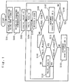
- connection is established using tone signals (S101).
- character synchronization is established (S102).
- a variable "invalid_count” is reset to zero (S103).
- a variable "VALID_FLAG” is reset to zero (S104).
- S105 a code is received (S105). Next, whether the code received in S105 is an illegal code or not is checked, and, if it is an illegal code (YES in S106), execution proceeds to S107 and, if it is not an illegal code (NO in S106), execution proceeds to S109.
- step of establishing character synchronization also, the same operations are performed as are performed in S103 to S112 after the establishment of character synchronization in order to make it possible to proceed to the step of establishing connection using tone signals (S101) when a transfer error is recognized to have occurred.
- the value of "invalid_count” is incremented by one every time an illegal code is received and is decremented by one every time two legal codes (i.e. codes that the remote device can transmit) are received consecutively.
- the value of "invalid_count” becomes equal to four, a transfer error is recognized to have occurred. That is, the frequency of errors in the received data is monitored and, when the frequency of errors in the received data is excessively high, a transfer error is recognized to have occurred.
- the data transfer method of a second embodiment of the invention relates to data transfer conforming to IEEE 1394 and using a single optical fiber.
- the second embodiment when connection is established between two devices using tone signals, one of the devices thus connected together is designated as primary and the other as secondary. Then, codes are allocated to the two devices in such a way that the IDLE codes that they transmit during reception or when they have no code to transmit differ depending on whether they are designated as primary or secondary and that those IDLE codes differ from any code that may be transmitted during ordinary data transfer.
- the codes allocated in the second embodiment are listed in Table 1.
- the IDLE code "P_IDLE” of the node designated as primary and the IDLE code “S_IDLE” of the node designated as secondary are both assigned a pattern that does not coincide with any of the other control codes or the data codes encoded by the 8B10B method even if bit displacement occurs during continuous data transmission.
- the other control codes and the data codes encoded by the 8B10B method are assigned patterns that do not coincide with "P_IDLE” or "S_IDLE” even if bit displacement occurs during continuous data transmission.
- connection is established using tone signals (S301).
- character synchronization is established (S302).
- one character representing a code is received (S303).
- the code received in S303 is the IDLE code that the local device transmits (YES in S304)
- execution proceeds to S305 and, if that code is not the IDLE code that the local device transmits (NO in S304), execution proceeds to S303.
- S305 one character representing a code is received. After S305, if the code received in S305 is the IDLE code that the local device transmits (YES in S306), connection is recognized to have been lost, and execution proceeds to the step of establishing connection using tone signals (S301). On the other hand, if that code is not the IDLE code that the local device transmits (NO in S306), execution proceeds to S303.
- step of establishing character synchronization also, the same operations are performed as are performed in S303 to S306 after the establishment of character synchronization in order to make it possible to proceed to the step of establishing connection using tone signals (S301) when connection is recognized to have been lost.
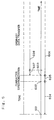
- Fig. 3 is a timing chart of the relevant signals observed when the remote device stops transmitting a signal.
- Reference numeral 401 indicates the signal transmitted from the remote device, which stops transmitting it at a time point 406.
- Reference numeral 402 indicates the signal transmitted from the remote device as represented in terms of the level of light intensity.
- the signal is illustrated as having a pattern consisting of alternating 1's and 0's, but this does not necessarily mean that the remote device transmits a code having a pattern consisting of alternating 1's and 0's.
- Reference numeral 403 indicates the signal transmitted from the local device, which transmits the IDLE code repeatedly.
- Reference numeral 404 indicates the signal transmitted from the local device as represented in terms of the level of light intensity.
- the signal is illustrated as having a pattern consisting of alternating 1's and 0's, but this does not necessarily mean that the local device transmits a code having a pattern consisting of alternating 1's and 0's.
- Reference numeral 405 indicates the signal received by the local device as represented in terms of the level of light intensity.
- This signal is a superimposed mixture of the light transmitted from the remote device (the remote-device light) and the light transmitted from the local device but reflected back on the way (the stray light).
- the remote-device light keeps sufficiently high the threshold level that is used to convert the received light into a binary electric signal. Since the level of the stray light is sufficiently low as compared with that of the remote-device light, only the remote-device light is received, and the stray light not.
- the remote-device light is absent. This causes the threshold level to become lower until, after some point, the stray light starts being received.
- the IDLE code will surely be transmitted sometime unless loss of connection is detected, and thus it is possible to detect loss of connection.
- the codes may be allocated in such a way that the codes other than the IDLE code have patterns that the remote device cannot transmit. However, on the grounds described above, to detect loss of connection more reliably, it is preferable to allocate the codes in such a way that the IDLE code has a pattern that the remote device cannot transmit.
- the second embodiment it is possible to distinguish whether the light being received is the remote-device light or the stray light on the basis of codes. This makes it possible to detect loss of connection more reliably than ever in bidirectional data transfer using a single optical fiber.
- the data transfer method of a third embodiment of the invention relates to data transfer conforming to IEEE 1394 and using a single optical fiber.
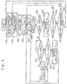
- the data transfer procedure used in the third embodiment will be described below with reference to the flow chart shown in Fig. 4.
- connection is established using tone signals (S501).
- character synchronization is established (S502).
- a timer is restarted (S503),
- a variable "invalid_count” is reset to zero (S504).
- a variable "VALID_FLAG” is reset to zero (S505).
- S511 the value of "VALID_FLAG” is referred to, and, if the value of the VALID_FLAG is not one (NO in S511), execution proceeds to S512 and, if the value of the VALID_FLAG is one (YES in S511), execution proceeds to S513. In S512, the value of the "VALID_FLAG" is set to one. After S512, execution proceeds to S506, where a code is received.
- step of establishing character synchronization also, the same operations are performed as are performed after the establishment of character synchronization in order to make it possible to recognize the occurrence of a transfer error.
- execution proceeds to the step of establishing connection using tone signals (S501).
- Reference numeral 601 indicates the time point at which tone signals start being transmitted to establish connection with the remote device when the local device has just been started up or has detected loss of connection.
- Reference numeral 602 indicates the time point at which predetermined codes start being transmitted to establish character synchronization after the establishment of connection with the remote device.
- Reference numeral 603 indicates the time point at which ordinary data transfer is started after the establishment of character synchronization.
- the time 604 required by the step of establishing connection using tone signals is about 400 ms.
- the time 605 required by the step of establishing character synchronization is about 160 ⁇ s.
- the step of establishing connection using tone signals takes a far longer time than the step of establishing character synchronization.
- the period 606 in which ordinary data transfer is being conducted if a transfer error is detected within the period 607 until a predetermined time has elapsed after the start of the ordinary data transfer, execution returns to the step of establishing connection using tone signals and, if a transfer error is detected in the other period 608 than the period 607, execution returns to the step of establishing character synchronization.
- the period 607 is set to have an appropriate length of time longer than the time required to detect a transfer error; specifically, about 125 ⁇ s suffices, which is far shorter than the time required by the step of establishing connection using tone signals.
- the data transfer method of a fourth embodiment of the invention relates to data transfer conforming to IEEE 1394 and using a single optical fiber.
- codes are allocated in the same manner as in the second embodiment.
- connection is established using tone signals (S901).
- character synchronization is established (S902).
- a timer is restarted (S903).
- a variable "invalid_count” is reset to zero (S904).
- a variable "IDLE_FLAG” is reset to zero (S905).
- a variable "VALID_FLAG” is reset to zero (S906).
- S907 a code is received (S907).
- whether the code received in S907 is an illegal code or not is checked, and, if it is not an illegal code (NO in S908), execution proceeds to S909 and, if it is an illegal code (YES in S908), execution proceeds to S913.
- step of establishing character synchronization also, the same operations are performed as are performed after the establishment of character synchronization in order to make it possible to recognize the occurrence of a transfer error resulting from frequent reception of illegal codes.
- execution proceeds to the step of establishing connection using tone signals (S901).
Landscapes
- Engineering & Computer Science (AREA)
- Signal Processing (AREA)
- Computer Networks & Wireless Communication (AREA)
- Small-Scale Networks (AREA)
- Communication Control (AREA)
- Information Transfer Between Computers (AREA)
- Debugging And Monitoring (AREA)
- Detection And Prevention Of Errors In Transmission (AREA)
- Monitoring And Testing Of Transmission In General (AREA)
Abstract
Description
| Arbitration Symbol | Character | ||
| rd<0 | rd>0 | ||
| QUIET | 000000 0000 | ||
| PREAMBLE | D10.2 | 010101 0101 | |
| P_IDLE S_TPBIAS_DISABLE | K.28.5 | 001111 1010 | 110000 0101 |
| S_IDLE P_TPBIAS_DISABLE | K.28.1 | 001111 1001 | 110000 0110 |
| REQUEST GRANT | K.28.6 | 001111 0110 | 110000 1001 |
| PARENT_NOTIFY | K.30.7 | 011110 1000 | 100001 0111 |
| DATA_PREFIX | K.27.7 | 110110 1000 | 001001 0111 |
| CHILD_NOTIFY IDENT_DONE | K.29.7 | 101110 1000 | 010001 0111 |
| DATA END | K.23.7 | 111010 1000 | 000101 0111 |
| SPEED200 NEXT SPEED | K.28.2 | 001111 0101 | 110000 1010 |
| SPEED400 END SPEED | K.28.3 | 001111 0011 | 110000 1100 |
| BUS_RESET SYNC CHARACTER | K.28.7 | 001111 1000 | |
| SUSPEND | K.28.0 | 001111 0100 | 110000 1011 |
| DISABLE_NOTIFY | K.28.4 | 001111 0010 | 110000 1101 |
Claims (13)
- A data transfer method comprising a connection establishment step of detecting connection with a remote device and setting parameters for data transfer, and a transfer execution step of starting data transfer after completion of the connection establishment step and continuing data transfer until a transfer error is recognized to have occurred,
wherein, in the transfer execution step, frequency of errors in received data is monitored and, when the frequency reaches a predetermined value, a transfer error is recognized to have occurred. - A data transfer method as claimed in claim 1,
wherein, when a transfer error is recognized to have occurred, execution proceeds to the connection establishment step. - A data transfer method as claimed in claim 1,
wherein the frequency of errors in received data is monitored with a counter that increments a count when a code the remote device cannot transmit is received and that decrements the count when a code the remote device can transmit is received. - A data transfer method as claimed in claim 3,
wherein a transfer error is recognized to have occurred when a count becomes four in a counter that increments the count by one every time a code the remote device cannot transmit is received and that decrements the count by one every time two codes the remote device can transmit are received consecutively. - A data transfer method that achieves bidirectional data transfer using a single optical fiber, the data transfer method comprising a connection establishment step of detecting connection with a remote device and setting parameters for data transfer, and a transfer execution step of starting data transfer after completion of the connection establishment step and continuing data transfer until a transfer error is recognized to have occurred,
wherein codes are allocated in such a way that codes a local device can transmit include codes the remote device cannot transmit, and, in the connection establishment step, a transfer error is recognized to have occurred when a code the remote device cannot transmit is received. - A data transfer method as claimed in claim 5,
wherein, when a transfer error is recognized to have occurred, execution proceeds to the connection establishment step. - A data transfer method as claimed in claim 5,
wherein data transfer is conducted in conformity with an IEEE 1394-1995 standard, and codes are allocated in such a way that an IDLE code of the local device is different from an IDLE code of the remote device and that the IDLE codes of those devices are different from other codes those devices can transmit. - A data transfer method as claimed in claim 5,
wherein, when a code the remote device cannot transmit is received, if the code is one the local device can transmit, connection is recognized to have been lost. - A data transfer method as claimed in claim 5,
wherein the transfer execution step comprises a synchronization establishment step of establishing character synchronization, and an ordinary transfer step of conducting ordinary data transfer after completion of the synchronization establishment step, and, when a transfer error is recognized to have occurred in the ordinary transfer step, execution proceeds to either the connection establishment step or the synchronization establishment step according to a time that has elapsed after the ordinary transfer step was started. - A data transfer method as claimed in claim 9,
wherein, when connection is recognized to have been lost, execution proceeds to the connection establishment step. - A data transfer method comprising a connection establishment step of detecting connection with a remote device and setting parameters for data transfer, and a transfer execution step of starting data transfer after completion of the connection establishment step and continuing data transfer until a transfer error is recognized to have occurred, the transfer execution step comprising a synchronization establishment step of establishing character synchronization, and an ordinary transfer step of conducting ordinary data transfer after completion of the synchronization establishment step,
wherein, when a transfer error is recognized to have occurred in the ordinary transfer step, execution proceeds to either the connection establishment step or the synchronization establishment step according to a time that has elapsed after the ordinary transfer step was started. - A data transfer method as claimed in claim 11,
wherein, when a transfer error is recognized to have occurred in the transfer execution step, if a predetermined time has not elapsed after the transfer execution step was started, execution proceeds to the connection establishment step and, if the predetermined time has elapsed after the transfer execution step was started, execution proceeds to the synchronization establishment step. - A data transfer method as claimed in claim 11,
wherein, when a transfer error is recognized to have occurred in the ordinary transfer step, if a predetermined time has not elapsed after the ordinary transfer step was started, execution proceeds to the connection establishment step and, if the predetermined time has elapsed after the ordinary transfer step was started, execution proceeds to the synchronization establishment step.
Applications Claiming Priority (2)
| Application Number | Priority Date | Filing Date | Title |
|---|---|---|---|
| JP2000119228 | 2000-04-20 | ||
| JP2000119228A JP2001308955A (en) | 2000-04-20 | 2000-04-20 | Transmission method |
Publications (3)
| Publication Number | Publication Date |
|---|---|
| EP1148679A2 true EP1148679A2 (en) | 2001-10-24 |
| EP1148679A3 EP1148679A3 (en) | 2004-01-14 |
| EP1148679B1 EP1148679B1 (en) | 2005-12-07 |
Family
ID=18630248
Family Applications (1)
| Application Number | Title | Priority Date | Filing Date |
|---|---|---|---|
| EP01109678A Expired - Lifetime EP1148679B1 (en) | 2000-04-20 | 2001-04-19 | Data transfer method |
Country Status (5)
| Country | Link |
|---|---|
| US (1) | US6802030B2 (en) |
| EP (1) | EP1148679B1 (en) |
| JP (1) | JP2001308955A (en) |
| KR (1) | KR100421829B1 (en) |
| DE (1) | DE60115529T2 (en) |
Cited By (2)
| Publication number | Priority date | Publication date | Assignee | Title |
|---|---|---|---|---|
| US7269355B2 (en) | 2003-05-30 | 2007-09-11 | Sharp Kabushiki Kaisha | Optical space communications device and control method thereof |
| CN103378862A (en) * | 2012-04-26 | 2013-10-30 | 瑞萨电子株式会社 | Encoder, decoder, and transmission system |
Families Citing this family (17)
| Publication number | Priority date | Publication date | Assignee | Title |
|---|---|---|---|---|
| JP3686957B2 (en) * | 2000-02-03 | 2005-08-24 | シャープ株式会社 | Communication device and communication method |
| US6640312B1 (en) * | 2000-08-01 | 2003-10-28 | National Instruments Corporation | System and method for handling device retry requests on a communication medium |
| US6961876B2 (en) * | 2001-09-21 | 2005-11-01 | International Business Machines Corporation | Automatic handling of link failures |
| US7301961B1 (en) | 2001-12-27 | 2007-11-27 | Cypress Semiconductor Corportion | Method and apparatus for configuring signal lines according to idle codes |
| JP3842145B2 (en) * | 2002-02-21 | 2006-11-08 | シャープ株式会社 | Communication apparatus and communication system |
| JP4059121B2 (en) * | 2003-03-27 | 2008-03-12 | セイコーエプソン株式会社 | Image display system for displaying an image based on information on the number of dots formed in a predetermined area |
| US7522641B2 (en) * | 2003-04-25 | 2009-04-21 | Farrokh Mohamadi | Ten gigabit copper physical layer system |
| US7706295B2 (en) * | 2003-09-09 | 2010-04-27 | Marvell Semiconductor, Inc. | Methods and apparatus for breaking and resynchronizing a data link |
| US8036244B2 (en) | 2004-08-06 | 2011-10-11 | Sharp Kabushiki Kaisha | Transmitter, receiver, communication system, communication method, non-transitory computer readable medium |
| JP4198741B2 (en) | 2005-01-28 | 2008-12-17 | シャープ株式会社 | Communication device, communication system, communication method, communication program, communication circuit |
| US8051182B2 (en) | 2005-01-28 | 2011-11-01 | Sharp Kabushiki Kaisha | Communication device, communication system, communication method, communication program, and communication circuit |
| US8284684B2 (en) | 2005-01-28 | 2012-10-09 | Sharp Kabushiki Kaisha | Communication device, communication system, communication method, and communication circuit |
| US7787391B2 (en) | 2005-01-28 | 2010-08-31 | Sharp Kabushiki Kaisha | Communication device, communication system, communication method, communication program, and communication circuit |
| WO2007055326A1 (en) * | 2005-11-10 | 2007-05-18 | Sharp Kabushiki Kaisha | Data transmitter, its control method, data receiver and its control method, data transmitting system, data transmitter controlling program, data receiver controlling program, and recording medium for recording the programs |
| JP4219950B2 (en) | 2006-10-16 | 2009-02-04 | シャープ株式会社 | COMMUNICATION DEVICE, COMMUNICATION METHOD, COMMUNICATION CIRCUIT, MOBILE PHONE, PROGRAM, AND COMPUTER-READABLE RECORDING MEDIUM CONTAINING THE PROGRAM |
| US9130746B1 (en) | 2011-01-27 | 2015-09-08 | Marvell International Ltd. | Single pair PHY with auto-negotiation |
| US9506272B2 (en) | 2013-08-16 | 2016-11-29 | The Hillman Group, Inc. | Two-piece key assembly |
Family Cites Families (22)
| Publication number | Priority date | Publication date | Assignee | Title |
|---|---|---|---|---|
| JPH05211479A (en) * | 1992-01-30 | 1993-08-20 | Fujitsu Ltd | Optical loopback method for same wavelength duplex transmitting device |
| US5331642A (en) * | 1992-09-01 | 1994-07-19 | International Business Machines Corporation | Management of FDDI physical link errors |
| US5513185A (en) * | 1992-11-23 | 1996-04-30 | At&T Corp. | Method and apparatus for transmission link error rate monitoring |
| JPH06350531A (en) | 1993-06-08 | 1994-12-22 | Fujitsu Ltd | Method and device for detecting optical input interruption |
| JPH07254890A (en) * | 1994-03-16 | 1995-10-03 | Fujitsu Ltd | Optical bidirectional transmission control system |
| GB2294617B (en) * | 1994-10-28 | 1998-11-25 | Sony Uk Ltd | Error rate monitor |
| US5778003A (en) * | 1995-03-30 | 1998-07-07 | Newbridge Networks Corporation | Loop-back detection using out-of-band signalling |
| US5933430A (en) * | 1995-08-12 | 1999-08-03 | Sony Corporation | Data communication method |
| JPH10133962A (en) * | 1996-11-01 | 1998-05-22 | Fujitsu Ltd | Transfer data verification method and device in data processing device provided with external recording device |
| US5859716A (en) * | 1996-01-18 | 1999-01-12 | Northern Telecom Limited | Self-stimulation signal detection in an optical transmission system |
| US5764651A (en) * | 1996-05-17 | 1998-06-09 | Integrated Device Technology, Inc. | Bit error rate detection system |
| JPH1022982A (en) * | 1996-07-03 | 1998-01-23 | Nec Corp | Transmission quality confirmation system |
| FI106082B (en) * | 1996-12-05 | 2000-11-15 | Nokia Networks Oy | A method for detecting feedback of a speech channel and speech processing device |
| JP3529263B2 (en) * | 1997-09-30 | 2004-05-24 | 日本電気株式会社 | Optical transmission / reception circuit for space transmission and space transmission device |
| JP3173457B2 (en) * | 1998-03-23 | 2001-06-04 | 日本電気株式会社 | Data communication device |
| JP3221401B2 (en) * | 1998-06-15 | 2001-10-22 | 日本電気株式会社 | Optical signal monitoring method and apparatus |
| JP3870561B2 (en) * | 1998-07-16 | 2007-01-17 | ソニー株式会社 | Apparatus and method for detecting interruption of optical fiber transmission |
| JP2000091993A (en) * | 1998-07-17 | 2000-03-31 | Kokusai Electric Co Ltd | Analog optical transmission system |
| JP2000092030A (en) * | 1998-09-09 | 2000-03-31 | Nec Corp | Optical transmitter |
| JP2000174733A (en) * | 1998-12-10 | 2000-06-23 | Totoku Electric Co Ltd | Optical receiving circuit |
| US6560725B1 (en) * | 1999-06-18 | 2003-05-06 | Madrone Solutions, Inc. | Method for apparatus for tracking errors in a memory system |
| JP2001148685A (en) * | 1999-11-22 | 2001-05-29 | Furukawa Electric Co Ltd:The | Frame communication method and apparatus |
-
2000
- 2000-04-20 JP JP2000119228A patent/JP2001308955A/en active Pending
-
2001
- 2001-04-19 DE DE60115529T patent/DE60115529T2/en not_active Expired - Fee Related
- 2001-04-19 EP EP01109678A patent/EP1148679B1/en not_active Expired - Lifetime
- 2001-04-19 KR KR10-2001-0021175A patent/KR100421829B1/en not_active Expired - Fee Related
- 2001-04-20 US US09/838,224 patent/US6802030B2/en not_active Expired - Fee Related
Cited By (2)
| Publication number | Priority date | Publication date | Assignee | Title |
|---|---|---|---|---|
| US7269355B2 (en) | 2003-05-30 | 2007-09-11 | Sharp Kabushiki Kaisha | Optical space communications device and control method thereof |
| CN103378862A (en) * | 2012-04-26 | 2013-10-30 | 瑞萨电子株式会社 | Encoder, decoder, and transmission system |
Also Published As
| Publication number | Publication date |
|---|---|
| EP1148679A3 (en) | 2004-01-14 |
| EP1148679B1 (en) | 2005-12-07 |
| JP2001308955A (en) | 2001-11-02 |
| DE60115529D1 (en) | 2006-01-12 |
| KR100421829B1 (en) | 2004-03-10 |
| US20010044914A1 (en) | 2001-11-22 |
| DE60115529T2 (en) | 2006-08-10 |
| KR20010098753A (en) | 2001-11-08 |
| US6802030B2 (en) | 2004-10-05 |
Similar Documents
| Publication | Publication Date | Title |
|---|---|---|
| EP1148679A2 (en) | Data transfer method | |
| US4706082A (en) | Serial data bus for intermodule data communications | |
| US20050080935A1 (en) | Device-side controller, host-side controller, communication controller, USB system, and packet communications method | |
| EP1237336A2 (en) | Media converter and link test technique using the same | |
| US20120250746A1 (en) | Transition interval coding for serial communication | |
| JP2001313646A (en) | Electronic apparatus and state control method for physical layer circuit thereof | |
| CA1278871C (en) | Method of data arbitration and collision detection on a data bus | |
| US7272744B2 (en) | Method for signaling during a transaction and receiving unit and system for use therewith | |
| US7394771B2 (en) | Apparatus and method for data communication including establishing communication using tone signal | |
| US5721891A (en) | Detection of N length bit serial communication stream | |
| KR101084060B1 (en) | Non-polar RS-485 communication device capable of data transmission by automatic polarity determination between GSM controllers | |
| KR100352567B1 (en) | Circuit and method for exchanging signals between nerwork nodes | |
| EP0505306B1 (en) | Control circuit for half-duplex/simplex interface in communication system | |
| EP1198783B1 (en) | Data carrier having means for synchronization with a received data stream | |
| CN116472686B (en) | Robust link synchronization in Ethernet networks | |
| WO2006054226A2 (en) | Bus communication system | |
| JPH11345193A (en) | Serial bus interface device and bus configuration method, recording medium, serial bus interface system | |
| JP3860017B2 (en) | Data communication method, transmission / reception circuit, information device including the transmission / reception circuit, and information communication network | |
| JPH08279803A (en) | Burst signal detection circuit | |
| CN113473055B (en) | Signal transmission control method, microprocessor and computer readable storage medium | |
| JP3437688B2 (en) | Bus type serial communication control method | |
| JP4065058B2 (en) | Remote reset device | |
| EP0718988B1 (en) | Optical Data communication system and method | |
| US6885715B1 (en) | Method and apparatus for synchronizing a network link | |
| CN120880477A (en) | Signal receiving device and method with channel recognition mechanism |
Legal Events
| Date | Code | Title | Description |
|---|---|---|---|
| PUAI | Public reference made under article 153(3) epc to a published international application that has entered the european phase |
Free format text: ORIGINAL CODE: 0009012 |
|
| AK | Designated contracting states |
Kind code of ref document: A2 Designated state(s): AT BE CH CY DE DK ES FI FR GB GR IE IT LI LU MC NL PT SE TR |
|
| AX | Request for extension of the european patent |
Free format text: AL;LT;LV;MK;RO;SI |
|
| PUAL | Search report despatched |
Free format text: ORIGINAL CODE: 0009013 |
|
| AK | Designated contracting states |
Kind code of ref document: A3 Designated state(s): AT BE CH CY DE DK ES FI FR GB GR IE IT LI LU MC NL PT SE TR |
|
| AX | Request for extension of the european patent |
Extension state: AL LT LV MK RO SI |
|
| RIC1 | Information provided on ipc code assigned before grant |
Ipc: 7H 04L 12/64 B Ipc: 7H 04L 12/40 A |
|
| 17P | Request for examination filed |
Effective date: 20040608 |
|
| 17Q | First examination report despatched |
Effective date: 20040720 |
|
| AKX | Designation fees paid |
Designated state(s): DE FR GB NL |
|
| GRAP | Despatch of communication of intention to grant a patent |
Free format text: ORIGINAL CODE: EPIDOSNIGR1 |
|
| GRAS | Grant fee paid |
Free format text: ORIGINAL CODE: EPIDOSNIGR3 |
|
| GRAA | (expected) grant |
Free format text: ORIGINAL CODE: 0009210 |
|
| AK | Designated contracting states |
Kind code of ref document: B1 Designated state(s): DE FR GB NL |
|
| REG | Reference to a national code |
Ref country code: GB Ref legal event code: FG4D |
|
| REF | Corresponds to: |
Ref document number: 60115529 Country of ref document: DE Date of ref document: 20060112 Kind code of ref document: P |
|
| PG25 | Lapsed in a contracting state [announced via postgrant information from national office to epo] |
Ref country code: GB Free format text: LAPSE BECAUSE OF NON-PAYMENT OF DUE FEES Effective date: 20060419 |
|
| ET | Fr: translation filed | ||
| PLBE | No opposition filed within time limit |
Free format text: ORIGINAL CODE: 0009261 |
|
| STAA | Information on the status of an ep patent application or granted ep patent |
Free format text: STATUS: NO OPPOSITION FILED WITHIN TIME LIMIT |
|
| PG25 | Lapsed in a contracting state [announced via postgrant information from national office to epo] |
Ref country code: NL Free format text: LAPSE BECAUSE OF NON-PAYMENT OF DUE FEES Effective date: 20061101 Ref country code: DE Free format text: LAPSE BECAUSE OF NON-PAYMENT OF DUE FEES Effective date: 20061101 |
|
| 26N | No opposition filed |
Effective date: 20060908 |
|
| GBPC | Gb: european patent ceased through non-payment of renewal fee |
Effective date: 20060419 |
|
| NLV4 | Nl: lapsed or anulled due to non-payment of the annual fee |
Effective date: 20061101 |
|
| REG | Reference to a national code |
Ref country code: FR Ref legal event code: ST Effective date: 20061230 |
|
| PG25 | Lapsed in a contracting state [announced via postgrant information from national office to epo] |
Ref country code: FR Free format text: LAPSE BECAUSE OF NON-PAYMENT OF DUE FEES Effective date: 20060502 |