EP1148616A2 - Battery charge optimizing system - Google Patents
Battery charge optimizing system Download PDFInfo
- Publication number
- EP1148616A2 EP1148616A2 EP01300972A EP01300972A EP1148616A2 EP 1148616 A2 EP1148616 A2 EP 1148616A2 EP 01300972 A EP01300972 A EP 01300972A EP 01300972 A EP01300972 A EP 01300972A EP 1148616 A2 EP1148616 A2 EP 1148616A2
- Authority
- EP
- European Patent Office
- Prior art keywords
- battery
- bus
- voltage
- current
- circuit
- Prior art date
- Legal status (The legal status is an assumption and is not a legal conclusion. Google has not performed a legal analysis and makes no representation as to the accuracy of the status listed.)
- Withdrawn
Links
Images


Classifications
-
- H—ELECTRICITY
- H02—GENERATION; CONVERSION OR DISTRIBUTION OF ELECTRIC POWER
- H02J—CIRCUIT ARRANGEMENTS OR SYSTEMS FOR SUPPLYING OR DISTRIBUTING ELECTRIC POWER; SYSTEMS FOR STORING ELECTRIC ENERGY
- H02J7/00—Circuit arrangements for charging or depolarising batteries or for supplying loads from batteries
- H02J7/02—Circuit arrangements for charging or depolarising batteries or for supplying loads from batteries for charging batteries from ac mains by converters
-
- H—ELECTRICITY
- H02—GENERATION; CONVERSION OR DISTRIBUTION OF ELECTRIC POWER
- H02J—CIRCUIT ARRANGEMENTS OR SYSTEMS FOR SUPPLYING OR DISTRIBUTING ELECTRIC POWER; SYSTEMS FOR STORING ELECTRIC ENERGY
- H02J7/00—Circuit arrangements for charging or depolarising batteries or for supplying loads from batteries
- H02J7/34—Parallel operation in networks using both storage and other dc sources, e.g. providing buffering
-
- H—ELECTRICITY
- H02—GENERATION; CONVERSION OR DISTRIBUTION OF ELECTRIC POWER
- H02J—CIRCUIT ARRANGEMENTS OR SYSTEMS FOR SUPPLYING OR DISTRIBUTING ELECTRIC POWER; SYSTEMS FOR STORING ELECTRIC ENERGY
- H02J2207/00—Indexing scheme relating to details of circuit arrangements for charging or depolarising batteries or for supplying loads from batteries
- H02J2207/20—Charging or discharging characterised by the power electronics converter
-
- Y—GENERAL TAGGING OF NEW TECHNOLOGICAL DEVELOPMENTS; GENERAL TAGGING OF CROSS-SECTIONAL TECHNOLOGIES SPANNING OVER SEVERAL SECTIONS OF THE IPC; TECHNICAL SUBJECTS COVERED BY FORMER USPC CROSS-REFERENCE ART COLLECTIONS [XRACs] AND DIGESTS
- Y02—TECHNOLOGIES OR APPLICATIONS FOR MITIGATION OR ADAPTATION AGAINST CLIMATE CHANGE
- Y02B—CLIMATE CHANGE MITIGATION TECHNOLOGIES RELATED TO BUILDINGS, e.g. HOUSING, HOUSE APPLIANCES OR RELATED END-USER APPLICATIONS
- Y02B40/00—Technologies aiming at improving the efficiency of home appliances, e.g. induction cooking or efficient technologies for refrigerators, freezers or dish washers
Definitions
- the present invention relates to batteries connected to direct current (DC) buses and, more specifically, to a charge optimizer interposed between the battery and the bus.
- DC direct current
- batteries are used as a power source for engine starting or as an emergency power source for a DC bus.
- a DC bus to which the battery is connected may itself be powered by a DC source, such as an engine-driven AC generator and a transformer rectifier unit (TRU) to convert AC to DC.
- TRU transformer rectifier unit
- the DC power source provides power for electrical loads of the system, in addition to providing power for charging the battery. If the DC power is interrupted, the battery immediately provides power to the DC bus.
- the battery nominal voltage is usually selected to be close to the DC bus voltage.
- the battery system with these components is simple and low cost so it is widely used in aircraft, electrical vehicle, and telecommunications applications.
- the battery is maintained in a float mode where the battery is fully charged and is essentially being topped off continuously because the DC power feeding the bus almost always is available. Therefore, the battery may be overcharged for long periods of time, resulting in battery overheating and electrolyte loss.
- the bus voltage is too low the battery could be undercharged, resulting in capacity fade. In both cases this results in reducing system reliability, as well as increasing battery system maintenance cost.
- One approach to these problems is to regulate the DC bus voltage in a way that is better for charging the battery.
- the DC bus voltage may be initially reduced following battery discharge to prevent large current in-rush transients. The voltage may then be raised above a normal charging level to increase the battery charging rate.
- Such systems provide better control over battery charging to prevent overheating of the battery, and allow the battery to be recharged more quickly.
- there is substantial increased cost and complexity in regulating the DC bus voltage and other aircraft systems connected to the bus may be affected.
- the DC bus is powered with an unregulated source, such as a TRU.
- an unregulated source such as a TRU.
- attempts have been made to intermittently connect the battery to the bus, as described, for example, in U.S. patent No. 3,703,675, which uses a contactor to control the battery charge and a parallel diode to provide a discharge path, and U.S. patent No. 5,969,436, which uses a MOSFET in series with a diode in order to control battery discharging.
- Another approach has been to add a "boost" circuit in series with an intermittently charged battery, to provide a voltage higher than the DC bus voltage for battery charging. See, for example, U.S. patent No. 4,061, 956.
- U.S. Patent No. 4,443,752 describes a similar technique using a MOSFET as a switch. In either of these systems, two series-connected power components are provided on the high current path between the DC bus and the battery, which may increase power dissipation during
- the present invention provides a high efficiency system for battery charging off a DC bus, at low cost and adaptable to changing conditions of the battery.
- two converters in parallel are used, one that can lower the battery voltage below the bus voltage or directly connect the bus to the battery and one that can raise the voltage to the battery above the bus voltage.
- the preferred system also optimizes battery charging by maintaining battery capacity, reduces water loss, and allows increased maintenance intervals.
- the first converter operates bi-directionally. It can perform as a simple contactor or as a voltage regulator with current limit.
- the primary function of this converter is to provide a path for battery "bulk” charge, i.e., the major portion of the charging, or for the battery to hold the bus voltage when the usual DC source is interrupted.
- the second converter in parallel with the first converter, provides an elevated voltage for battery topping and trickle charging. Since the current for these charges is small, the second converter is designed only to handle low power operation. This reduces the cost and improves the efficiency, while achieving the optimal control of battery charging.
- a battery charge optimizer in accordance with the present invention has two buck converters, one operating from a voltage higher than the DC bus.
- the system in accordance with the present invention operates in three modes.
- the charge starts at a current limited “bulk mode” in which the charging current is controlled.
- a “topping mode” is used where a predetermined current level is maintained but the battery voltage is free to rise.
- the charge is transacted to a second stage of topping mode where the voltage is maintained for a relatively short period.
- a third mode "trickle mode” or “balance mode” is effected in which the charging current is maintained at a small value.
- the BCO in accordance with the present invention is interposed between the DC bus and the battery, but the battery still can be directly connected to a potential load, such as the starter of an auxiliary power unit (APU).
- a potential load such as the starter of an auxiliary power unit (APU).
- APU auxiliary power unit
- the present invention can be used in a system having a DC bus supplying power to one or more components of a system, such as in an aircraft.
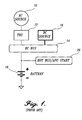
- a known system is illustrated diagrammatically in FIGURE 1.
- a three-phase generator 10 driven by an aircraft engine supplies an AC output to a transformer rectifier unit (TRU) 12.
- TRU supplies a nominal voltage to the DC bus 14, such as 28 volts.
- Other sources may supply power to the bus, such as a ground power source 16, when the aircraft is parked and the engines are not running.
- a battery 18 will supply power to the bus if the other power sources are not available.
- the battery also may supply larger loads, represented by box 20, such as the starter of an auxiliary power unit (APU).
- APU auxiliary power unit
- the larger load may be connected directly to the battery output, i.e., without being supplied by way of the bus 14.
- battery charging is by way of the floating bus voltage. If the battery is completely discharged, a larger than optimal current may be supplied. If the DC bus voltage is too low then the battery may be undercharged and experience battery fade. Similarly, a fully charged battery will still receive the bus voltage and may overheat and/or experience increased water loss, or the battery may be otherwise damaged or have its useful life lessened.
- FIGURE 2 One approach to solving the battery charging problems of the system of FIGURE 1 is illustrated in FIGURE 2.
- a regulated power source 22 supplies power to the DC bus 14 based, at least in part, on the condition and state of the battery 18.
- the bus voltage may be raised or lowered, which can affect other components connected to the bus, and which, in general, is expensive.
- FIGURE 3 is a block diagram of a representative application of an optimizing system in accordance with the present invention.
- the supply of power to the DC bus 14 is conventional, coming from an AC source 10, such as a generator driven by an aircraft engine, through a TRU 12, or by way of an alternative DC source 16, such as a ground power source.
- a battery charge optimizer (BCO) 24 is interposed between the bus 14 and the battery 18.
- the potential high load 20 for the battery (labeled "hot bus/APU start" in FIGURE 3) can be connected directly to the battery, i.e., at the opposite side of the BCO 24 from the DC bus 14.
- the BCO is bi-directional such that the battery may supply power to the DC bus if the potential sources represented at the top of FIGURE 3 fail and/or are disconnected.
- FIGURE 4 is a block diagram of the BCO unit 24, with the DC bus 14 at the left and the potential high load 20 at the right.
- a gate drive and control circuit 26 senses the voltage at the output terminal of the battery 18 (such as at point A of FIGURE 4) and a conventional current sensor 28 detects the current flowing to the battery (such as a Hall current sensor which provides a varying voltage output depending on the sensed current).
- the gate drive and control circuit 26 provides a switching signal to a first circuit 29 having a pair of MOSFETs Q1 and Q2 in anti-series or to a MOSFET Q3 of a voltage boost DC/DC converter circuit ("second circuit”) 30.
- the gate drive and control circuit 26 will activate MOSFETs Q1 and Q2, in which case the DC bus 14 is connected directly to the battery 18 through a smoothing inductor L1.
- the gate drive and control circuit 26 can actuate MOSFET Q3 which results in adding the voltage of a DC/DC converter 32 to the voltage of the DC bus 14, i.e., the voltage to the battery is boosted for optimal charging under certain conditions as described below.
- FIGURE 5 A schematic of the gate drive and control circuit 26 is illustrated in FIGURE 5.
- the battery current sensing signal and voltage sensing signal (points A and B in FIGURE 4 and FIGURE 5) are supplied to a logic array or microcontroller 34.
- the current sensing signal is supplied as one input to an operational amplifier IC2 having negative feedback.
- the other input is a reference voltage labeled I ref in FIGURE 5 because such voltage is indicative of a desired current.
- the voltage sensing signal is supplied to another operational amplifier IC1 having negative feedback, with a voltage reference input V ref from the logic array/microcontroller.
- the outputs of these two amplifiers are supplied to a comparator IC3, having a voltage from a ramp generator 36 as its other input.
- the output of the comparator IC3 is supplied to a pair of AND gates IC4 and IC5, one of which receives a boost mode signal (high or low; on or off) from the logic array/microcontroller 34 and the other of which receives a bulk mode signal (high or low; on or off) from the logic array/microcontroller.
- Operation can best be described with respect to a representative embodiment, although it should be understood that other operational parameters may be chosen depending on the particular application.
- a 24-volt nominal battery may be used.
- a Hall current sensor having an output of about 0.8 volt per 10 amps detected current can be used.
- the error amplifier circuits IC1 and IC2 have sufficient gain to maintain V ref equal to point A and I ref equal to point B.
- the ramp generator 36 can have an output as represented in FIGURE 6, a repeating essentially linear ramp of a frequency of 40KHz (25 ⁇ seconds duration) ranging from one to four volts.
- the low voltage of the discharged battery is sensed at point A and supplied as an input to the logic array/microcontroller 34.
- the logic array/microcontroller supplies a "high" signal to turn on the bulk mode MOSFETs Q1 and Q2, which actuates a closed circuit condition of this part of the BCO as compared to an open circuit condition if Q1 and Q2 are off.
- the DC bus voltage is applied at the positive input of the battery, through Q1 and Q2 and inductor L1.
- a current limit can be supplied by way of I ref .
- I ref may be 6.4 volts which corresponds to a maximum charging current of 80 amps.
- the system is tuned such that if the battery current sensing signal at the negative input of amplifier IC2 rises to a level indicating 80 amps charging current, the signal supplied to the positive input of comparator IC3 is approximately four volts.
- the voltage of the signal supplied by the ramp generator to the negative input of the comparator is less than the voltage of the signal from amplifier IC2 for the entire duty cycle of the ramp. Consequently, a constant high output from the comparator is supplied to the AND gate IC5 which also is receiving a high "bulk mode” input from the logic array/microcontroller.
- the logic array/microcontroller supplies a low "boost mode” input to AND gate IC4.
- MOSFETs Q1 and Q2 are turned on. So long as the sensed current is below 80 amps, the output of amplifier IC2 will be greater than the maximum value of each ramp. If, however, the sensed current exceeds 80 amps, the output of amplifier IC2 is lessened to a point where it intersects the upper portion of each ramp. In that case, the bulk mode AND gate IC5 will intermittently turn off MOSFETs Q1 and Q2, and the turnoff time will increase for increasing sensed current. The system is brought back into balance by an effective maximum charging current of 80 amps.
- boost mode charging state with the bus connected to the battery continues until the battery charging current falls to a predetermined value, 10 amps in the representative application.
- I ref is set at 0.8 volts by the logic array/microcontroller 34, corresponding to 10 amps charging current, and the boost mode is activated, i.e., the bulk mode signal to AND gate IC5 goes low and the boost mode signal goes high to AND gate IC4, which actuates the boost circuit to a closed circuit condition between the bus and the battery from an open current condition.
- An increased voltage is provided by way of the boost circuit 30 (FIGURE 4) consisting of the isolated DC/DC 32 converter and MOSFET Q3.
- the ramp generator works in conjunction with amplifier IC2 as described above, but with the lower reference voltage at the positive input so that a constant current of 10 amps is maintained.
- the 10 amp charging is continued until the voltage at point A reaches 30 volts, and for a predetermined period thereafter, one-half hour in the representative embodiment.
- the system switches to the "balance mode” which also can be referred to as "trickle mode” where a very small current is maintained by setting I ref .
- the charging current would be 0.1 amp to 0.5 amp during the balance mode, which is achieved by setting the I ref value at a corresponding low voltage, and the boost circuit MOSFET Q3 remains on with MOSFETS Q1 and Q2 off.
- bulk mode is activated for voltages at point A (battery voltage) less than the DC bus voltage and a detected charging current of 10 amps to 80 amps. No more than 80 amps can be supplied. This mode is also actuated if power to the bus is lost.
- the BCO switches to boost mode when the charging amperage falls to 10 amps.
- Boost mode continues by supplying a 10 amp constant current until the voltage at point A is 30 volts, and for the predetermined period thereafter, whereupon the circuit switches to balance mode for supplying the very low trickle current, such as .1 amp to .5 amp.
Abstract
Description
- The present invention relates to batteries connected to direct current (DC) buses and, more specifically, to a charge optimizer interposed between the battery and the bus.
- In some applications, such as aircraft applications, batteries are used as a power source for engine starting or as an emergency power source for a DC bus. Obviously, it is important to maintain the battery in a fully charged condition and to charge it after use. In known systems, a DC bus to which the battery is connected may itself be powered by a DC source, such as an engine-driven AC generator and a transformer rectifier unit (TRU) to convert AC to DC. During normal operation, the DC power source provides power for electrical loads of the system, in addition to providing power for charging the battery. If the DC power is interrupted, the battery immediately provides power to the DC bus. In order to reduce the voltage variation on the DC bus, the battery nominal voltage is usually selected to be close to the DC bus voltage.
- The battery system with these components is simple and low cost so it is widely used in aircraft, electrical vehicle, and telecommunications applications. However, in this configuration, the battery is maintained in a float mode where the battery is fully charged and is essentially being topped off continuously because the DC power feeding the bus almost always is available. Therefore, the battery may be overcharged for long periods of time, resulting in battery overheating and electrolyte loss. On the other hand, if the bus voltage is too low the battery could be undercharged, resulting in capacity fade. In both cases this results in reducing system reliability, as well as increasing battery system maintenance cost. In addition, it may be undesirable to keep a completely discharged battery floating on the bus because the battery may draw a large transient current during initial charging and overloading the DC source.
- One approach to these problems is to regulate the DC bus voltage in a way that is better for charging the battery. For example, the DC bus voltage may be initially reduced following battery discharge to prevent large current in-rush transients. The voltage may then be raised above a normal charging level to increase the battery charging rate. Such systems provide better control over battery charging to prevent overheating of the battery, and allow the battery to be recharged more quickly. However, there is substantial increased cost and complexity in regulating the DC bus voltage, and other aircraft systems connected to the bus may be affected.
- More often, the DC bus is powered with an unregulated source, such as a TRU. In these systems, attempts have been made to intermittently connect the battery to the bus, as described, for example, in U.S. patent No. 3,703,675, which uses a contactor to control the battery charge and a parallel diode to provide a discharge path, and U.S. patent No. 5,969,436, which uses a MOSFET in series with a diode in order to control battery discharging. Another approach has been to add a "boost" circuit in series with an intermittently charged battery, to provide a voltage higher than the DC bus voltage for battery charging. See, for example, U.S. patent No. 4,061, 956. Also, U.S. Patent No. 4,443,752 describes a similar technique using a MOSFET as a switch. In either of these systems, two series-connected power components are provided on the high current path between the DC bus and the battery, which may increase power dissipation during operation.
- The present invention provides a high efficiency system for battery charging off a DC bus, at low cost and adaptable to changing conditions of the battery. In the preferred embodiment, two converters in parallel are used, one that can lower the battery voltage below the bus voltage or directly connect the bus to the battery and one that can raise the voltage to the battery above the bus voltage. The preferred system also optimizes battery charging by maintaining battery capacity, reduces water loss, and allows increased maintenance intervals.
- The first converter operates bi-directionally. It can perform as a simple contactor or as a voltage regulator with current limit. The primary function of this converter is to provide a path for battery "bulk" charge, i.e., the major portion of the charging, or for the battery to hold the bus voltage when the usual DC source is interrupted.
- The second converter, in parallel with the first converter, provides an elevated voltage for battery topping and trickle charging. Since the current for these charges is small, the second converter is designed only to handle low power operation. This reduces the cost and improves the efficiency, while achieving the optimal control of battery charging.
- In the preferred embodiment, a battery charge optimizer (BCO) in accordance with the present invention has two buck converters, one operating from a voltage higher than the DC bus.
- The system in accordance with the present invention operates in three modes. For a discharged battery, the charge starts at a current limited "bulk mode" in which the charging current is controlled. When a desired charging state is reached, detected by the decreasing charging current, a "topping mode" is used where a predetermined current level is maintained but the battery voltage is free to rise. When the rising voltage reaches a temperature compensated set point, the charge is transacted to a second stage of topping mode where the voltage is maintained for a relatively short period. Thereafter, a third mode, "trickle mode" or "balance mode", is effected in which the charging current is maintained at a small value.
- In a representative aircraft application, the BCO in accordance with the present invention is interposed between the DC bus and the battery, but the battery still can be directly connected to a potential load, such as the starter of an auxiliary power unit (APU).
- The foregoing aspects and many of the attendant advantages of this invention will become more readily appreciated as the same become better understood by reference to the following detailed description, when taken in conjunction with the accompanying drawings, wherein:
- FIGURE 1 (prior art) is a block diagram of a known power supply system using a DC bus in combination with a battery;
- FIGURE 2 (prior art) is a block diagram of a second known power supply system using a DC bus in combination with a battery;
- FIGURE 3 is a block diagram of a battery charge optimizing system in accordance with the present invention;
- FIGURE 4 is a more detailed diagram of a component of the system of FIGURE 3;
- FIGURE 5 is a more detailed block diagram of a component of the system in accordance with the present invention as represented in FIGURE 4; and
- FIGURE 6 is a graph illustrating operation of part of the system of FIGURE 5.
-
- The present invention can be used in a system having a DC bus supplying power to one or more components of a system, such as in an aircraft. A known system is illustrated diagrammatically in FIGURE 1. A three-
phase generator 10 driven by an aircraft engine supplies an AC output to a transformer rectifier unit (TRU) 12. The TRU supplies a nominal voltage to theDC bus 14, such as 28 volts. Other sources may supply power to the bus, such as aground power source 16, when the aircraft is parked and the engines are not running. - In such a system a
battery 18 will supply power to the bus if the other power sources are not available. The battery also may supply larger loads, represented bybox 20, such as the starter of an auxiliary power unit (APU). In such an arrangement, the larger load may be connected directly to the battery output, i.e., without being supplied by way of thebus 14. - In the system of FIGURE 1, battery charging is by way of the floating bus voltage. If the battery is completely discharged, a larger than optimal current may be supplied. If the DC bus voltage is too low then the battery may be undercharged and experience battery fade. Similarly, a fully charged battery will still receive the bus voltage and may overheat and/or experience increased water loss, or the battery may be otherwise damaged or have its useful life lessened.
- One approach to solving the battery charging problems of the system of FIGURE 1 is illustrated in FIGURE 2. In such a system, a
regulated power source 22 supplies power to theDC bus 14 based, at least in part, on the condition and state of thebattery 18. In such a system, the bus voltage may be raised or lowered, which can affect other components connected to the bus, and which, in general, is expensive. - FIGURE 3 is a block diagram of a representative application of an optimizing system in accordance with the present invention. As represented toward the top of the Figure, the supply of power to the
DC bus 14 is conventional, coming from anAC source 10, such as a generator driven by an aircraft engine, through aTRU 12, or by way of analternative DC source 16, such as a ground power source. A battery charge optimizer (BCO) 24 is interposed between thebus 14 and thebattery 18. The potentialhigh load 20 for the battery (labeled "hot bus/APU start" in FIGURE 3) can be connected directly to the battery, i.e., at the opposite side of theBCO 24 from theDC bus 14. In addition, the BCO is bi-directional such that the battery may supply power to the DC bus if the potential sources represented at the top of FIGURE 3 fail and/or are disconnected. - FIGURE 4 is a block diagram of the
BCO unit 24, with theDC bus 14 at the left and the potentialhigh load 20 at the right. In general, a gate drive andcontrol circuit 26 senses the voltage at the output terminal of the battery 18 (such as at point A of FIGURE 4) and a conventionalcurrent sensor 28 detects the current flowing to the battery (such as a Hall current sensor which provides a varying voltage output depending on the sensed current). The gate drive andcontrol circuit 26 provides a switching signal to afirst circuit 29 having a pair of MOSFETs Q1 and Q2 in anti-series or to a MOSFET Q3 of a voltage boost DC/DC converter circuit ("second circuit") 30. - More specifically, under the desired parameters, such as those described in more detail below, the gate drive and
control circuit 26 will activate MOSFETs Q1 and Q2, in which case theDC bus 14 is connected directly to thebattery 18 through a smoothing inductor L1. Alternatively, the gate drive andcontrol circuit 26 can actuate MOSFET Q3 which results in adding the voltage of a DC/DC converter 32 to the voltage of theDC bus 14, i.e., the voltage to the battery is boosted for optimal charging under certain conditions as described below. - A schematic of the gate drive and
control circuit 26 is illustrated in FIGURE 5. The battery current sensing signal and voltage sensing signal (points A and B in FIGURE 4 and FIGURE 5) are supplied to a logic array ormicrocontroller 34. The current sensing signal is supplied as one input to an operational amplifier IC2 having negative feedback. The other input is a reference voltage labeled Iref in FIGURE 5 because such voltage is indicative of a desired current. The voltage sensing signal is supplied to another operational amplifier IC1 having negative feedback, with a voltage reference input Vref from the logic array/microcontroller. The outputs of these two amplifiers are supplied to a comparator IC3, having a voltage from aramp generator 36 as its other input. The output of the comparator IC3 is supplied to a pair of AND gates IC4 and IC5, one of which receives a boost mode signal (high or low; on or off) from the logic array/microcontroller 34 and the other of which receives a bulk mode signal (high or low; on or off) from the logic array/microcontroller. - Operation can best be described with respect to a representative embodiment, although it should be understood that other operational parameters may be chosen depending on the particular application. For an aircraft having a 28-volt nominal DC bus supplied by an unregulated DC source such as a TRU, a 24-volt nominal battery may be used. A Hall current sensor having an output of about 0.8 volt per 10 amps detected current can be used. The error amplifier circuits IC1 and IC2 have sufficient gain to maintain Vref equal to point A and Iref equal to point B. The
ramp generator 36 can have an output as represented in FIGURE 6, a repeating essentially linear ramp of a frequency of 40KHz (25µ seconds duration) ranging from one to four volts. - Starting from a situation in which the battery is fully discharged, the low voltage of the discharged battery is sensed at point A and supplied as an input to the logic array/
microcontroller 34. The logic array/microcontroller supplies a "high" signal to turn on the bulk mode MOSFETs Q1 and Q2, which actuates a closed circuit condition of this part of the BCO as compared to an open circuit condition if Q1 and Q2 are off. The DC bus voltage is applied at the positive input of the battery, through Q1 and Q2 and inductor L1. A current limit can be supplied by way of Iref. In a representative embodiment, Iref may be 6.4 volts which corresponds to a maximum charging current of 80 amps. More specifically, referring to FIGURES 5 and 6, the system is tuned such that if the battery current sensing signal at the negative input of amplifier IC2 rises to a level indicating 80 amps charging current, the signal supplied to the positive input of comparator IC3 is approximately four volts. The voltage of the signal supplied by the ramp generator to the negative input of the comparator is less than the voltage of the signal from amplifier IC2 for the entire duty cycle of the ramp. Consequently, a constant high output from the comparator is supplied to the AND gate IC5 which also is receiving a high "bulk mode" input from the logic array/microcontroller. The logic array/microcontroller supplies a low "boost mode" input to AND gate IC4. The result is that MOSFETs Q1 and Q2 are turned on. So long as the sensed current is below 80 amps, the output of amplifier IC2 will be greater than the maximum value of each ramp. If, however, the sensed current exceeds 80 amps, the output of amplifier IC2 is lessened to a point where it intersects the upper portion of each ramp. In that case, the bulk mode AND gate IC5 will intermittently turn off MOSFETs Q1 and Q2, and the turnoff time will increase for increasing sensed current. The system is brought back into balance by an effective maximum charging current of 80 amps. - This "bulk mode" charging state with the bus connected to the battery continues until the battery charging current falls to a predetermined value, 10 amps in the representative application. At this stage, Iref is set at 0.8 volts by the logic array/
microcontroller 34, corresponding to 10 amps charging current, and the boost mode is activated, i.e., the bulk mode signal to AND gate IC5 goes low and the boost mode signal goes high to AND gate IC4, which actuates the boost circuit to a closed circuit condition between the bus and the battery from an open current condition. An increased voltage is provided by way of the boost circuit 30 (FIGURE 4) consisting of the isolated DC/DC 32 converter and MOSFET Q3. The ramp generator works in conjunction with amplifier IC2 as described above, but with the lower reference voltage at the positive input so that a constant current of 10 amps is maintained. The 10 amp charging is continued until the voltage at point A reaches 30 volts, and for a predetermined period thereafter, one-half hour in the representative embodiment. - Then, the system switches to the "balance mode" which also can be referred to as "trickle mode" where a very small current is maintained by setting Iref. In the representative embodiment the charging current would be 0.1 amp to 0.5 amp during the balance mode, which is achieved by setting the Iref value at a corresponding low voltage, and the boost circuit MOSFET Q3 remains on with MOSFETS Q1 and Q2 off.
- In summary, bulk mode is activated for voltages at point A (battery voltage) less than the DC bus voltage and a detected charging current of 10 amps to 80 amps. No more than 80 amps can be supplied. This mode is also actuated if power to the bus is lost. The BCO switches to boost mode when the charging amperage falls to 10 amps. Boost mode continues by supplying a 10 amp constant current until the voltage at point A is 30 volts, and for the predetermined period thereafter, whereupon the circuit switches to balance mode for supplying the very low trickle current, such as .1 amp to .5 amp.
- In the case of a main power source failure, bulk mode (Q1 and Q2 on) results in powering the bus by way of the battery. For efficient operation of the
large load 20, the power connection can be directly to the battery output terminal. A simple and cost effective power supply can be used for the bus, with optimal charging and maintenance for the battery. - While the preferred embodiment of the invention has been illustrated and described, it will be appreciated that various changes can be made therein without departing from the spirit and scope of the invention.
Claims (4)
- In a power supply system having a DC bus (14) and a battery (18) connected to the bus (14), an optimizer (24) connected between the bus (14) and the battery (18), said optimizer (24) comprising:a first circuit (29) connected in series between the bus (14) and the battery (18) and actuatable between an open circuit condition and a closed circuit condition, the first circuit (29) in the closed circuit condition interconnecting the bus (14) and the battery (18) bi-directionally for supplying charging current to the battery (18) from the bus (14) or power from the battery (18) to the bus (14) depending on the relative voltages of the bus (14) and the battery (18);a second circuit (30) connected in series between the bus (14) and the battery (18), in parallel with the first circuit (29), and actuatable between an open circuit condition and a closed circuit condition, the second circuit (30) in the closed circuit condition providing a voltage higher than the voltage of the bus (14) to the battery (18); anda controller (26) sensing the voltage of the battery (18) and sensing current flowing to the battery (18) and actuating the first and second circuits (29, 30) as a function of the sensed voltage and current.
- In the power supply system defined in Claim 1, the controller (26) actuating only the first circuit (29) and not the second circuit (30) when the sensed voltage is below a predetermined amount and the sensed current is in a predetermined range.
- In the power supply system defined in Claim 2, the controller (26) actuating only the second circuit (30) and not the first circuit (29) when the sensed current is below a predetermined current.
- In the power supply defined in Claim 3, the controller (26) intermittently actuating one of the first and second circuits (29, 30) when the sensed voltage is above a predetermined voltage for maintaining a small trickle current from the bus (14) to the battery (18).
Applications Claiming Priority (2)
| Application Number | Priority Date | Filing Date | Title |
|---|---|---|---|
| US09/540,108 US6188199B1 (en) | 2000-03-31 | 2000-03-31 | Battery charge optimizing system |
| US540108 | 2000-03-31 |
Publications (2)
| Publication Number | Publication Date |
|---|---|
| EP1148616A2 true EP1148616A2 (en) | 2001-10-24 |
| EP1148616A3 EP1148616A3 (en) | 2004-11-24 |
Family
ID=24154019
Family Applications (1)
| Application Number | Title | Priority Date | Filing Date |
|---|---|---|---|
| EP01300972A Withdrawn EP1148616A3 (en) | 2000-03-31 | 2001-02-02 | Battery charge optimizing system |
Country Status (2)
| Country | Link |
|---|---|
| US (1) | US6188199B1 (en) |
| EP (1) | EP1148616A3 (en) |
Cited By (1)
| Publication number | Priority date | Publication date | Assignee | Title |
|---|---|---|---|---|
| CN104816833A (en) * | 2015-04-20 | 2015-08-05 | 中国科学院长春光学精密机械与物理研究所 | Small aircraft power supply system and integrated design method thereof |
Families Citing this family (18)
| Publication number | Priority date | Publication date | Assignee | Title |
|---|---|---|---|---|
| JP3863273B2 (en) * | 1997-12-26 | 2006-12-27 | 富士通株式会社 | Power supply |
| WO2002011267A2 (en) * | 2000-07-28 | 2002-02-07 | International Power Systems, Inc. | Dc to dc converter and power management system |
| FR2824203B1 (en) * | 2001-04-27 | 2003-06-13 | Agence Spatiale Europeenne | POWER SUPPLY CONVERTER |
| US6738692B2 (en) | 2001-06-25 | 2004-05-18 | Sustainable Energy Technologies | Modular, integrated power conversion and energy management system |
| JP4211715B2 (en) * | 2004-08-23 | 2009-01-21 | 株式会社デンソー | In-vehicle power supply system |
| SE528232C2 (en) | 2005-04-08 | 2006-09-26 | Creator Teknisk Utveckling Ab | The battery charging system |
| US7701173B2 (en) * | 2005-12-13 | 2010-04-20 | Research In Motion Limited | Charging and power supply for mobile devices |
| US7808125B1 (en) | 2006-07-31 | 2010-10-05 | Sustainable Energy Technologies | Scheme for operation of step wave power converter |
| US8154247B2 (en) * | 2007-06-14 | 2012-04-10 | Nokia Corporation | Portable telecommunications device |
| WO2009044293A2 (en) * | 2007-06-04 | 2009-04-09 | Sustainable Energy Technologies | Prediction scheme for step wave power converter and inductive inverter topology |
| US8552690B2 (en) * | 2009-11-06 | 2013-10-08 | Rally Manufacturing, Inc. | Method and system for automatically detecting a voltage of a battery |
| US8575895B2 (en) | 2011-03-29 | 2013-11-05 | Rally Manufacturing, Inc. | Method and device for voltage detection and charging of electric battery |
| US9306465B2 (en) | 2011-06-10 | 2016-04-05 | Lear Corporation | Method for controlling a converter having variable frequency control and system for powering a vehicle load using same |
| US9083202B2 (en) * | 2012-12-18 | 2015-07-14 | Fca Us Llc | Alternator control for battery charging |
| US9634512B1 (en) * | 2013-12-03 | 2017-04-25 | Google Inc. | Battery backup with bi-directional converter |
| WO2016013451A1 (en) * | 2014-07-22 | 2016-01-28 | ローム株式会社 | Charging circuit, electronic device using same, and charger |
| US9992853B2 (en) * | 2016-08-03 | 2018-06-05 | Samsung Electronics Co., Ltd. | Mobile X-ray apparatus including a battery management system |
| US11146079B2 (en) * | 2018-05-29 | 2021-10-12 | Alencon Acquisition Co., Llc | Bi-directional optimizers for battery storage systems with galvanic isolation |
Citations (2)
| Publication number | Priority date | Publication date | Assignee | Title |
|---|---|---|---|---|
| GB2247366A (en) * | 1990-08-21 | 1992-02-26 | Peter Murray | A two state constant current battery charging system |
| EP0865141A2 (en) * | 1997-03-13 | 1998-09-16 | Sony Corporation | Charger system, charging method and secondary battery system |
Family Cites Families (12)
| Publication number | Priority date | Publication date | Assignee | Title |
|---|---|---|---|---|
| FR2080156A5 (en) | 1970-02-25 | 1971-11-12 | Aerospatiale | |
| US3857082A (en) * | 1972-09-29 | 1974-12-24 | Tympanium Corp | Electronic voltage regulator for battery charging |
| US4016473A (en) * | 1975-11-06 | 1977-04-05 | Utah Research & Development Co., Inc. | DC powered capacitive pulse charge and pulse discharge battery charger |
| GB1578332A (en) | 1976-03-09 | 1980-11-05 | Chloride Group Ltd | Automatic electric battery charging apparatus |
| IL59777A (en) | 1980-04-04 | 1983-05-15 | Israel Aircraft Ind Ltd | Temperature-regulated multiplebattery charging system |
| US4443752A (en) | 1982-08-30 | 1984-04-17 | Utah Research & Development Co., Inc. | Solid state battery charger |
| US4536696A (en) | 1983-07-14 | 1985-08-20 | At&T Bell Laboratories | Buck-boost converter with dual-mode control for battery charging |
| US4649333A (en) | 1985-04-30 | 1987-03-10 | Levitt-Safety Limited | Two terminal nicad battery charger with battery voltage and temperature sensing |
| US5250891A (en) | 1991-05-13 | 1993-10-05 | Milwaukee Electric Tool Corporation | Battery charging method and apparatus |
| US5623197A (en) | 1994-04-25 | 1997-04-22 | Lucas Aerospace Power Equipment Corporation | Active control of battery charging profile by generator control unit |
| US5864221A (en) | 1997-07-29 | 1999-01-26 | Trw Inc. | Dedicated avionics standby power supply |
| US5969436A (en) | 1998-02-27 | 1999-10-19 | Lucent Technologies Inc. | Connect/disconnect circuit for a reserve battery and method of operation thereof |
-
2000
- 2000-03-31 US US09/540,108 patent/US6188199B1/en not_active Expired - Lifetime
-
2001
- 2001-02-02 EP EP01300972A patent/EP1148616A3/en not_active Withdrawn
Patent Citations (2)
| Publication number | Priority date | Publication date | Assignee | Title |
|---|---|---|---|---|
| GB2247366A (en) * | 1990-08-21 | 1992-02-26 | Peter Murray | A two state constant current battery charging system |
| EP0865141A2 (en) * | 1997-03-13 | 1998-09-16 | Sony Corporation | Charger system, charging method and secondary battery system |
Cited By (1)
| Publication number | Priority date | Publication date | Assignee | Title |
|---|---|---|---|---|
| CN104816833A (en) * | 2015-04-20 | 2015-08-05 | 中国科学院长春光学精密机械与物理研究所 | Small aircraft power supply system and integrated design method thereof |
Also Published As
| Publication number | Publication date |
|---|---|
| US6188199B1 (en) | 2001-02-13 |
| EP1148616A3 (en) | 2004-11-24 |
Similar Documents
| Publication | Publication Date | Title |
|---|---|---|
| US6188199B1 (en) | Battery charge optimizing system | |
| US6414403B2 (en) | Power unit | |
| US9667094B1 (en) | Battery backup system for uninterrupted power supply | |
| US7906934B2 (en) | Power source apparatus and control method of the power source apparatus | |
| EP0464694B1 (en) | Power source unit for an automotive vehicle | |
| US7352154B2 (en) | Electrical system control for a vehicle | |
| US5241217A (en) | UPS with input commutation between AC and DC sources of power | |
| JP3973638B2 (en) | Power supply unit and power supply system having the same | |
| US6577106B2 (en) | Multi-functional AC/DC converter | |
| US10737586B2 (en) | Converter architecture | |
| US20080036419A1 (en) | Battery isolator | |
| WO2006101188A1 (en) | Dc-dc convertir system | |
| US9407143B2 (en) | Vehicle power-supply unit | |
| EP1225082A2 (en) | Control device for fuel cell powered vehicle | |
| JP2006094690A (en) | Power switching device | |
| US20050151508A1 (en) | Battery isolator | |
| US6812672B2 (en) | Electric charge control device and load driving device using the same | |
| JP3796353B2 (en) | DC / DC converter power supply system | |
| US20230170831A1 (en) | Work machine | |
| US11456669B2 (en) | Voltage supply to a load and battery | |
| JP3330157B2 (en) | Power supply system | |
| JPH03124201A (en) | Auxiliary battery charger for electric car | |
| GB2243961A (en) | DC-DC Power supply circuit | |
| JPH074207U (en) | Vehicle power supply | |
| JP2679348B2 (en) | Satellite bus voltage control system |
Legal Events
| Date | Code | Title | Description |
|---|---|---|---|
| PUAI | Public reference made under article 153(3) epc to a published international application that has entered the european phase |
Free format text: ORIGINAL CODE: 0009012 |
|
| AK | Designated contracting states |
Kind code of ref document: A2 Designated state(s): AT BE CH CY DE DK ES FI FR GB GR IE IT LI LU MC NL PT SE TR |
|
| AX | Request for extension of the european patent |
Free format text: AL;LT;LV;MK;RO;SI |
|
| PUAL | Search report despatched |
Free format text: ORIGINAL CODE: 0009013 |
|
| AK | Designated contracting states |
Kind code of ref document: A3 Designated state(s): AT BE CH CY DE DK ES FI FR GB GR IE IT LI LU MC NL PT SE TR |
|
| AX | Request for extension of the european patent |
Extension state: AL LT LV MK RO SI |
|
| 17P | Request for examination filed |
Effective date: 20050513 |
|
| AKX | Designation fees paid |
Designated state(s): AT BE CH CY DE DK ES FI FR GB GR IE IT LI LU MC NL PT SE TR |
|
| 17Q | First examination report despatched |
Effective date: 20091105 |
|
| STAA | Information on the status of an ep patent application or granted ep patent |
Free format text: STATUS: THE APPLICATION IS DEEMED TO BE WITHDRAWN |
|
| 18D | Application deemed to be withdrawn |
Effective date: 20100518 |