EP1148594A2 - Rolling bearing unit - Google Patents
Rolling bearing unit Download PDFInfo
- Publication number
- EP1148594A2 EP1148594A2 EP01109184A EP01109184A EP1148594A2 EP 1148594 A2 EP1148594 A2 EP 1148594A2 EP 01109184 A EP01109184 A EP 01109184A EP 01109184 A EP01109184 A EP 01109184A EP 1148594 A2 EP1148594 A2 EP 1148594A2
- Authority
- EP
- European Patent Office
- Prior art keywords
- rolling bearing
- drive unit
- contact piece
- diselectrification
- bearing unit
- Prior art date
- Legal status (The legal status is an assumption and is not a legal conclusion. Google has not performed a legal analysis and makes no representation as to the accuracy of the status listed.)
- Granted
Links
- 238000005096 rolling process Methods 0.000 title claims abstract description 68
- 230000005611 electricity Effects 0.000 claims abstract description 19
- 230000003068 static effect Effects 0.000 claims abstract description 17
- XEEYBQQBJWHFJM-UHFFFAOYSA-N Iron Chemical compound [Fe] XEEYBQQBJWHFJM-UHFFFAOYSA-N 0.000 abstract description 20
- 229910052742 iron Inorganic materials 0.000 abstract description 10
- 230000005540 biological transmission Effects 0.000 abstract description 4
- 206010040844 Skin exfoliation Diseases 0.000 description 19
- 238000004299 exfoliation Methods 0.000 description 19
- 229910052739 hydrogen Inorganic materials 0.000 description 11
- 239000001257 hydrogen Substances 0.000 description 11
- UFHFLCQGNIYNRP-UHFFFAOYSA-N Hydrogen Chemical compound [H][H] UFHFLCQGNIYNRP-UHFFFAOYSA-N 0.000 description 10
- 230000002093 peripheral effect Effects 0.000 description 7
- XAGFODPZIPBFFR-UHFFFAOYSA-N aluminium Chemical compound [Al] XAGFODPZIPBFFR-UHFFFAOYSA-N 0.000 description 4
- 229910052782 aluminium Inorganic materials 0.000 description 4
- 239000004519 grease Substances 0.000 description 4
- XLYOFNOQVPJJNP-UHFFFAOYSA-N water Substances O XLYOFNOQVPJJNP-UHFFFAOYSA-N 0.000 description 3
- 229910000881 Cu alloy Inorganic materials 0.000 description 2
- DMFGNRRURHSENX-UHFFFAOYSA-N beryllium copper Chemical compound [Be].[Cu] DMFGNRRURHSENX-UHFFFAOYSA-N 0.000 description 2
- 230000000694 effects Effects 0.000 description 2
- 238000010998 test method Methods 0.000 description 2
- LDXJRKWFNNFDSA-UHFFFAOYSA-N 2-(2,4,6,7-tetrahydrotriazolo[4,5-c]pyridin-5-yl)-1-[4-[2-[[3-(trifluoromethoxy)phenyl]methylamino]pyrimidin-5-yl]piperazin-1-yl]ethanone Chemical compound C1CN(CC2=NNN=C21)CC(=O)N3CCN(CC3)C4=CN=C(N=C4)NCC5=CC(=CC=C5)OC(F)(F)F LDXJRKWFNNFDSA-UHFFFAOYSA-N 0.000 description 1
- 229910000838 Al alloy Inorganic materials 0.000 description 1
- 230000001133 acceleration Effects 0.000 description 1
- 238000005260 corrosion Methods 0.000 description 1
- 230000007797 corrosion Effects 0.000 description 1
- 230000007423 decrease Effects 0.000 description 1
- 238000011156 evaluation Methods 0.000 description 1
- -1 hydrogen ions Chemical class 0.000 description 1
- 239000000314 lubricant Substances 0.000 description 1
- 230000001050 lubricating effect Effects 0.000 description 1
- 239000010687 lubricating oil Substances 0.000 description 1
- 230000003746 surface roughness Effects 0.000 description 1
- 229920003002 synthetic resin Polymers 0.000 description 1
- 239000000057 synthetic resin Substances 0.000 description 1
Images
Classifications
-
- F—MECHANICAL ENGINEERING; LIGHTING; HEATING; WEAPONS; BLASTING
- F16—ENGINEERING ELEMENTS AND UNITS; GENERAL MEASURES FOR PRODUCING AND MAINTAINING EFFECTIVE FUNCTIONING OF MACHINES OR INSTALLATIONS; THERMAL INSULATION IN GENERAL
- F16C—SHAFTS; FLEXIBLE SHAFTS; ELEMENTS OR CRANKSHAFT MECHANISMS; ROTARY BODIES OTHER THAN GEARING ELEMENTS; BEARINGS
- F16C41/00—Other accessories, e.g. devices integrated in the bearing not relating to the bearing function as such
- F16C41/002—Conductive elements, e.g. to prevent static electricity
-
- F—MECHANICAL ENGINEERING; LIGHTING; HEATING; WEAPONS; BLASTING
- F16—ENGINEERING ELEMENTS AND UNITS; GENERAL MEASURES FOR PRODUCING AND MAINTAINING EFFECTIVE FUNCTIONING OF MACHINES OR INSTALLATIONS; THERMAL INSULATION IN GENERAL
- F16C—SHAFTS; FLEXIBLE SHAFTS; ELEMENTS OR CRANKSHAFT MECHANISMS; ROTARY BODIES OTHER THAN GEARING ELEMENTS; BEARINGS
- F16C19/00—Bearings with rolling contact, for exclusively rotary movement
- F16C19/52—Bearings with rolling contact, for exclusively rotary movement with devices affected by abnormal or undesired conditions
-
- H—ELECTRICITY
- H01—ELECTRIC ELEMENTS
- H01R—ELECTRICALLY-CONDUCTIVE CONNECTIONS; STRUCTURAL ASSOCIATIONS OF A PLURALITY OF MUTUALLY-INSULATED ELECTRICAL CONNECTING ELEMENTS; COUPLING DEVICES; CURRENT COLLECTORS
- H01R13/00—Details of coupling devices of the kinds covered by groups H01R12/70 or H01R24/00 - H01R33/00
- H01R13/648—Protective earth or shield arrangements on coupling devices, e.g. anti-static shielding
- H01R13/6485—Electrostatic discharge protection
-
- H—ELECTRICITY
- H01—ELECTRIC ELEMENTS
- H01R—ELECTRICALLY-CONDUCTIVE CONNECTIONS; STRUCTURAL ASSOCIATIONS OF A PLURALITY OF MUTUALLY-INSULATED ELECTRICAL CONNECTING ELEMENTS; COUPLING DEVICES; CURRENT COLLECTORS
- H01R39/00—Rotary current collectors, distributors or interrupters
- H01R39/64—Devices for uninterrupted current collection
- H01R39/643—Devices for uninterrupted current collection through ball or roller bearing
Definitions
- the present invention relates to a rolling bearing unit suitable for use in a belt transmission system and a belt drive system disposed around various machine motors or a vehicle engine (for example, an alternator, an intermediate pulley, an electromagnetic clutch, a compressor and a water pomp, etc.).
- a vehicle engine for example, an alternator, an intermediate pulley, an electromagnetic clutch, a compressor and a water pomp, etc.
- an energizing bearing which is disclosed in the registered Japanese Utility Model No. 2540952.
- this bearing there is interposed a spiral-shaped spring between the end portion of the inner peripheral surface of an outer ring and the end portion of the outer peripheral surface of an inner ring that is opposed to the end portion of the inner peripheral surface of the outer ring.
- On one end side of the spring there is formed an inner ring side sliding contact portion which can be slidingly contacted with the inner ring outer peripheral surface end portion.
- an outer ring side sliding contact portion which can be slidingly contacted with the outer ring inner peripheral surface end portion.
- the leading end portion of the outer ring side sliding contact portion is extended substantially up to the same position of the inner ring side sliding contact portion in the peripheral direction, thereby being able to prevent a discharge phenomenon which otherwise could occur between the raceways of the rolling bearing and rolling bodies.
- the energizing bearing disclosed in the above-cited registered Japanese Utility Model No. 2540952 interposes the spiral-shaped spring between the rolling bodies and inner and outer rings to thereby eliminate a potential difference between them in order to be able to prevent the discharge phenomenon from occurring between the raceways of the rolling bearing and rolling bodies.
- lubricating oil between the inner ring and rolling bodies as well as between the outer ring and rolling bodies and thus there exists a clearance of several microns between them; and, therefore, the existence of a potential difference of several volts has been confirmed between them.
- Japanese Patent Unexamined Publication No. Hei. 11-117758 there is disclosed a member for engine electrically mounting auxiliary machinery which can prevent static electricity from flowing to the bearing side to thereby prevent the early exfoliation of the bearing due to the electrolyticallyproducedhydrogen.
- a member for engine electrically mounting auxiliary machinery which can prevent static electricity from flowing to the bearing side to thereby prevent the early exfoliation of the bearing due to the electrolyticallyproducedhydrogen.
- an electrically insulated part formed of synthetic resin having low thermal strength is used in the drive pulley thereof, the strength of the drive pulley is not sufficient.
- the present invention aims at eliminating the above-mentioned drawbacks found in the rolling bearing units in the related art. Accordingly, it is an object of the invention to provide a rolling bearing unit which removes static electricity occurring due to the rotation friction of a drive unit in front of the rolling bearing to thereby be able to prevent the early exfoliation of the rolling bearing.
- a rolling bearing unit which a rolling bearing having an inner ring and an outer ring, one of the inner and outer rings supported by a support member, the other of the inner and outer rings supporting a rotary member rotatably, a drive unit for driving and rotating the rotary member, and a diselectrification member disposed in front of the rolling bearing that is disposed closest to the drive unit in an axial direction of the rotary member, for removing static electricity to be generated form the drive unit.
- the drive unit can comprises a pulley mounted on the rotary member and a belt for driving the pulley.
- the diselectrification member can be comprises a contact type diselectrification device interposed between the above pulley and ground.
- the rolling bearing unit can be applied to the vehicle alternator.
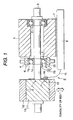
- Fig. 1 is a schematic view of a bearing unit having a diselectrification device according to the invention.
- Fig. 1 is a schematic view of an embodiment of an inner ring rotation type of rolling bearing unit for an alternator in which diselectrification member according to the invention is incorporated in a drive unit thereof.
- Two rolling bearings 1 and 2 are disposed with a clearance between them in the axial direction of the rolling bearing unit.
- An inner ring 1n of the rolling bearing 1 is fitted with and mounted on a shaft 3 serving as a common support member in such a manner that the inner ring 1n can be rotated integrally with the shaft 3.
- An outer ring 1g of the rolling bearing 1 is fitted into, and fixed to and held by a subordinate aluminum housing 4.
- the subordinate aluminum housing 4 is prevented against rotation by striking a plurality of fixing pins 6 into the end face of a main aluminum housing 5.
- the iron pulley 11 and ground 8 are connected together by a contact type diselectrification member E.
- the present diselectrification member (which is here in after referred to as an diselectrification device) E includes a spring member 15 made of beryllium copper alloy, and a fixed contact piece 16 made of beryllium copper alloy and fixed to the leading end of the spring member 15.
- the terminal end of the spring member 15 is fixed to the ground 8.
- the fixed contact piece 16 fixed to the leading end of the spring member 15 can be pressure contacted with a rotary contact piece 17 having a semispherical-shaped section due to the elastic force of the spring member 15.
- the rotary contact piece 17 is projectingly provided on the side surface of the iron pulley 11.
- the rolling bearing unit when compared with other auxiliary machinery such as an intermediate pulley, an electromagnetic clutch, or a compressor, the rolling bearing unit is used in a severe condition: that is, it can be exposed to high temperatures, high vibrations and high loads; and, since the housing thereof is made of aluminum alloy, the rolling bearing is easy to deform and is thus easy to exfoliate. Therefore, in the present comparison test, while using he rolling bearing unit for an alternator shown in Fig. 1 as the test apparatus, two cases were checked. In one case, the diselectrification device E is provided and the pressing loads of the contact pieces (16, 17) thereof are varied; and, in the other case, the diselectrification device E is not provided. Specifically, both cases were checked for the generated potential differences, the bearing life of the bearing 1 used as the test sample, and the presence or absence of exfoliation. By the way, the bearing 2 was treated only as a support bearing.
- the drive unit 13 is a static electricity generating source, in which there is generated static electricity (current) i due to friction between the iron pulley 11 and transmission (V-groove) belt 12.
- the current (staticelectricity) i is divided into a current i 1 and a current i 2 .
- the current i 1 flows from the iron pulley 11 directly to the shaft 3 made of iron, whereas the current is flows through the diselectrification device E.
- the current i 2 is grounded and, therefore, i 2 > i 1 .
- the generated static electricity i current i 1 , so that all of the current flows through the shaft 3 to the test bearing 1.
- the potential difference between the inner ring In and outer ring 1g of the test bearing 1 was measured using a potential difference meter 23 which is connected between a fixed contact piece 21 pressure contacted by a spring to the end face of the rotating inner ring In and a fixed contact piece 22 mounted on the end face of the fixedly supported outer ring 1g.
- test bearing 1 there was used JIS nominal number 6303.
- the calculated life of the bearing at the then time is 1670 hours and, therefore, the test finishing time was set for 2000 hours.
- test number n 10 test pieces were used for all of the embodiments and comparison examples.
- the diselectrification device E is not used.
- the inner ring In of the test bearing 1 was assumed to be positive and the outer ring Ig (fixedring) was assumednegative, when the potential difference between them was measured, it was confirmed that the potential difference was 5V.
- the diselectrification device E is not used.
- the outer ring 1g was set negative and a dc voltage was applied to the outer ring 1g, so that the potential difference between the rotating ring and fixed ring was 10V.
- the potential difference between the rotating and fixed rings was 1.0V.
- the hydrogen density of the component (outer ring 1g) of the rolling bearing after the rotation test was measured using the "rolling bearing lubricant evaluation method" disclosed in Japanese Patent Unexamined Publication No. Hei. 11-94704, it could be confirmed that the increment of the hydrogen density was 0.2 ppm.
- the L 10 life was 1718 hrs., which is longer than the calculated life (1670 hrs.).
- the rolling bearing unit of an inner ring rotating type is not limited to this but, for example, also in the case of a rolling bearing unit of an outer ring rotating type such as a rolling bearing unit for an intermediate pulley mounted around the vehicle engine auxiliary machinery, by mounting a grounding terminal on the pulley to thereby remove electricity, there can be obtained similar effects to the rolling bearing unit of an inner ring rotating type.
Landscapes
- Engineering & Computer Science (AREA)
- General Engineering & Computer Science (AREA)
- Mechanical Engineering (AREA)
- Rolling Contact Bearings (AREA)
- Motor Or Generator Frames (AREA)
Abstract
Description
| Potential Difference between Rotating and Fixed Rings (V) | L10 Life (hr) | Presence or Absence of Exfoliation | |
| Embodiment 1 | 1.0 | 1718 | 3/10 Outer |
| Embodiment | |||
| 2 | 0.5 | 2000 | No |
| Embodiment | |||
| 3 | 0.2 | 2000 | No exfoliation |
| Embodiment 4 | 0.1 | 2000 | No exfoliation |
| Comparison Example 1 | 5 | 341 | 10/10 Outer ring exfoliation |
| Comparison Example 2 | 10 | 159 | 10/10 Outer ring exfoliation |
| Comparison Example 3 | 2 | 534 | 10/10 Outer ring exfoliation |
Claims (8)
- A rolling bearing unit comprising:a rolling bearing including an inner ring and an outer ring, one of the inner and outer rings being supported by a support member, the other of the inner and outer rings supporting a rotary member rotatably;a drive unit for driving and rotating the rotary member; anda diselectrification member connected with the drive unit, for removing static electricity to be generated from said drive unit.
- The rolling bearing unit as set forth in Claim 1, wherein a plurality of rolling bearings are provided in said rolling bearing unit, and said diselectrification member is disposed between the rolling bearing being nearest from said drive unit and said drive unit.
- The rolling bearing unit as set forth in Claim 1, wherein said diselectrification member is disposed between said rolling bearing and said drive unit.
- The rolling bearing unit as set forth in any of Claims 1-3, wherein the support member is mounted on a grounding member through an insulated member.
- The rolling bearing unit as set forth in any of Claims 1-4, wherein said diselectrification member comprises a contact piece being contacted with said drive unit or a grounding member, and an elastic member for energizing said contact piece against said drive unit or the grounding member, said elastic member connected to the contact piece in one end thereof and connected to the grounding member or said drive unit in the other end thereof.
- The rolling bearing unit as set forth in any of Claims 1-5, wherein a potential difference between said inner ring and said outer ring is set at 1V or less.
- The rolling bearing unit as set forth in any of Claims 1-6, wherein said rolling bearing unit is applied for use in a vehicle engine auxiliary machinery.
- The rolling bearing unit as set forth in Claim 1, wherein said diselectrification member comprises a rotary contact piece provided on said drive unit, a fixed contact piece pressure contacted with the rotary contact piece, and an elastic member fixed to the fixed contact piece at one end thereof and fixed to a grounding member at the other end thereof, for energizing the fixed contact piece against the rotary contact piece.
Applications Claiming Priority (2)
| Application Number | Priority Date | Filing Date | Title |
|---|---|---|---|
| JP2000118801 | 2000-04-20 | ||
| JP2000118801A JP2001304281A (en) | 2000-04-20 | 2000-04-20 | Rolling bearing unit |
Publications (3)
| Publication Number | Publication Date |
|---|---|
| EP1148594A2 true EP1148594A2 (en) | 2001-10-24 |
| EP1148594A3 EP1148594A3 (en) | 2003-05-02 |
| EP1148594B1 EP1148594B1 (en) | 2004-09-15 |
Family
ID=18629871
Family Applications (1)
| Application Number | Title | Priority Date | Filing Date |
|---|---|---|---|
| EP01109184A Expired - Lifetime EP1148594B1 (en) | 2000-04-20 | 2001-04-12 | Rolling bearing unit |
Country Status (4)
| Country | Link |
|---|---|
| US (1) | US6530694B2 (en) |
| EP (1) | EP1148594B1 (en) |
| JP (1) | JP2001304281A (en) |
| DE (1) | DE60105482T2 (en) |
Cited By (2)
| Publication number | Priority date | Publication date | Assignee | Title |
|---|---|---|---|---|
| DE102004025665A1 (en) * | 2004-05-26 | 2005-12-29 | Mtu Friedrichshafen Gmbh | Current collector for an internal combustion engine has a rotor and a stator housed in a device for directing current from the rotor to a reference potential |
| WO2009121511A1 (en) * | 2008-04-03 | 2009-10-08 | Thyssenkrupp Transrapid Gmbh | Bearing, having a grounded, rotatable bearing race |
Families Citing this family (18)
| Publication number | Priority date | Publication date | Assignee | Title |
|---|---|---|---|---|
| JP4689224B2 (en) * | 2004-10-08 | 2011-05-25 | 株式会社リコー | Drive transmission device and image forming apparatus |
| JP4704102B2 (en) * | 2005-05-12 | 2011-06-15 | Ntn株式会社 | Bearing test apparatus and bearing test method |
| US20110204734A1 (en) * | 2005-06-25 | 2011-08-25 | Orlowski David C | Motor Grounding Seal |
| US7436091B2 (en) * | 2005-06-29 | 2008-10-14 | Detroit Diesel Corporation | Method and system of limiting arcing of rotating member |
| DE102005033655A1 (en) * | 2005-07-19 | 2007-02-01 | Dr.Ing.H.C. F. Porsche Ag | Electrostatic charge conducting device for electrical generator of internal combustion engine, has bypass pin placed between housing wall and front side of pulley in generator, where device is completely arranged in pulley`s outer periphery |
| JP4739947B2 (en) * | 2005-12-28 | 2011-08-03 | Ntn株式会社 | Bearing test apparatus and bearing test method |
| JP4739949B2 (en) * | 2005-12-28 | 2011-08-03 | Ntn株式会社 | Bearing test apparatus and bearing test method |
| JP2008239706A (en) | 2007-03-26 | 2008-10-09 | Kyodo Yushi Co Ltd | Grease composition and bearing |
| DE202007018482U1 (en) * | 2007-07-09 | 2008-10-16 | Von Ardenne Anlagentechnik Gmbh | Transport device with a monitoring device |
| US7547228B1 (en) | 2008-07-10 | 2009-06-16 | Honeywell International Inc. | Joining means for device components |
| JP5771950B2 (en) * | 2009-10-30 | 2015-09-02 | 日本精工株式会社 | Bearing test equipment |
| JP5428760B2 (en) * | 2009-10-30 | 2014-02-26 | 日本精工株式会社 | Bearing white peeling test equipment |
| JP5659481B2 (en) * | 2009-11-16 | 2015-01-28 | 日本精工株式会社 | Bearing test method |
| DE102013216995B3 (en) * | 2013-08-27 | 2015-02-12 | Schaeffler Technologies Gmbh & Co. Kg | Method for operating a bearing arrangement |
| DE102014225225B4 (en) * | 2014-12-09 | 2022-09-15 | Robert Bosch Gmbh | Electrical machine with an equipotential bonding device |
| JP6314858B2 (en) * | 2015-01-28 | 2018-04-25 | 株式会社豊田自動織機 | Weft measurement and storage device in loom |
| US10077157B2 (en) * | 2015-09-10 | 2018-09-18 | AMF automation Technologies, LLC | Static dissipative sprocket for a conveyor belt system |
| CN106058598B (en) * | 2016-05-24 | 2018-11-13 | 南京伶机宜动驱动技术有限公司 | The highly reliable contact rotation system of nested type and combinations thereof formula System and method for |
Family Cites Families (15)
| Publication number | Priority date | Publication date | Assignee | Title |
|---|---|---|---|---|
| US2375304A (en) * | 1943-10-19 | 1945-05-08 | Us Ind Chemicals Inc | Static eliminator |
| US4623952A (en) * | 1986-01-28 | 1986-11-18 | Magnetic Peripherals Inc. | Damped static eliminator for disk drives |
| JPS63231454A (en) * | 1987-03-20 | 1988-09-27 | Fuji Photo Film Co Ltd | Heater for photosensitive material |
| DE4002402C2 (en) * | 1990-01-27 | 1996-07-11 | Renk Ag | bearings |
| JPH077613B2 (en) * | 1990-02-02 | 1995-01-30 | 東京電力株式会社 | Suspended lightning arrester |
| JPH04160225A (en) * | 1990-10-25 | 1992-06-03 | Ntn Corp | Grease enclosing bearing |
| JP2739009B2 (en) * | 1991-05-31 | 1998-04-08 | インターナショナル・ビジネス・マシーンズ・コーポレイション | Disk drive |
| US5233499A (en) * | 1991-08-21 | 1993-08-03 | Westinghouse Electric Corp. | Automatic shaft ground conditioner |
| US5804903A (en) * | 1993-10-22 | 1998-09-08 | Fisher; Rodney R. | Motor shaft discharge device |
| JP3054581B2 (en) * | 1995-04-27 | 2000-06-19 | 三洋電機株式会社 | Washing machine |
| US5716193A (en) * | 1995-07-21 | 1998-02-10 | Eurocopter France | Installation for affording electrical continuity for rotorcraft rotor |
| JP3536614B2 (en) | 1997-09-19 | 2004-06-14 | 日本精工株式会社 | Evaluation method for lubricants for rolling bearings |
| JPH11117758A (en) * | 1997-10-13 | 1999-04-27 | Nippon Seiko Kk | Engine electrical accessory parts |
| JPH11219549A (en) * | 1998-02-02 | 1999-08-10 | Alps Electric Co Ltd | Rotating head device |
| DE19824022C2 (en) * | 1998-05-29 | 2003-10-30 | Skf Gmbh | Rolling bearings with current bridge |
-
2000
- 2000-04-20 JP JP2000118801A patent/JP2001304281A/en not_active Withdrawn
-
2001
- 2001-04-12 EP EP01109184A patent/EP1148594B1/en not_active Expired - Lifetime
- 2001-04-12 DE DE60105482T patent/DE60105482T2/en not_active Expired - Fee Related
- 2001-04-19 US US09/837,177 patent/US6530694B2/en not_active Expired - Fee Related
Cited By (3)
| Publication number | Priority date | Publication date | Assignee | Title |
|---|---|---|---|---|
| DE102004025665A1 (en) * | 2004-05-26 | 2005-12-29 | Mtu Friedrichshafen Gmbh | Current collector for an internal combustion engine has a rotor and a stator housed in a device for directing current from the rotor to a reference potential |
| DE102004025665B4 (en) * | 2004-05-26 | 2006-07-13 | Mtu Friedrichshafen Gmbh | Current collector for an internal combustion engine has a rotor and a stator housed in a device for directing current from the rotor to a reference potential |
| WO2009121511A1 (en) * | 2008-04-03 | 2009-10-08 | Thyssenkrupp Transrapid Gmbh | Bearing, having a grounded, rotatable bearing race |
Also Published As
| Publication number | Publication date |
|---|---|
| JP2001304281A (en) | 2001-10-31 |
| US6530694B2 (en) | 2003-03-11 |
| EP1148594B1 (en) | 2004-09-15 |
| DE60105482T2 (en) | 2005-01-20 |
| US20010046338A1 (en) | 2001-11-29 |
| EP1148594A3 (en) | 2003-05-02 |
| DE60105482D1 (en) | 2004-10-21 |
Similar Documents
| Publication | Publication Date | Title |
|---|---|---|
| EP1148594B1 (en) | Rolling bearing unit | |
| US10270320B1 (en) | Motor grounding seal | |
| US20070138748A1 (en) | Motor ground seal | |
| CN102422368B (en) | Current diverter ring | |
| JP2002039334A (en) | Rolling bearing unit | |
| US5577847A (en) | Supporting arrangement for a bearing in an electric motor | |
| EP3913245A1 (en) | Method for diagnosing rolling device | |
| JPH0735147A (en) | Rotating electric machine | |
| CN211778536U (en) | Parallel bearing rotor system, motor and electric appliance | |
| WO1996019678A1 (en) | Ball for ball bearings | |
| JP5428760B2 (en) | Bearing white peeling test equipment | |
| JPH07333200A (en) | Electrolytic corrosion evaluation test equipment for bearings | |
| JP2934697B2 (en) | Anti-corrosion rolling bearing | |
| Prasad et al. | Bearing selection for high-speed electrical machine | |
| GB2068479A (en) | Electrical machine | |
| US20070004235A1 (en) | Method and system of limiting arcing of rotating member | |
| JP2000052986A (en) | Bearing device for railway vehicles | |
| Scheuermann et al. | Development of a bearing test bench to investigate root causes of bearing current damages | |
| JPH11117758A (en) | Engine electrical accessory parts | |
| Klenk et al. | Conductive Simmerrings help prevent electrical discharge machining in modern electrical powertrains | |
| US7535140B2 (en) | On-vehicle belt-driven alternator | |
| JPH04160225A (en) | Grease enclosing bearing | |
| JP2003230248A (en) | AC generator for vehicles | |
| Srinidhi et al. | Bearing wear due to mechanical stresses and electrical currents | |
| JP4122898B2 (en) | Rolling bearings and alternators for automotive electrical accessories |
Legal Events
| Date | Code | Title | Description |
|---|---|---|---|
| PUAI | Public reference made under article 153(3) epc to a published international application that has entered the european phase |
Free format text: ORIGINAL CODE: 0009012 |
|
| 17P | Request for examination filed |
Effective date: 20010412 |
|
| AK | Designated contracting states |
Kind code of ref document: A2 Designated state(s): AT BE CH CY DE DK ES FI FR GB GR IE IT LI LU MC NL PT SE TR |
|
| AX | Request for extension of the european patent |
Free format text: AL;LT;LV;MK;RO;SI |
|
| PUAL | Search report despatched |
Free format text: ORIGINAL CODE: 0009013 |
|
| AK | Designated contracting states |
Designated state(s): AT BE CH CY DE DK ES FI FR GB GR IE IT LI LU MC NL PT SE TR |
|
| AX | Request for extension of the european patent |
Extension state: AL LT LV MK RO SI |
|
| 17Q | First examination report despatched |
Effective date: 20030825 |
|
| GRAP | Despatch of communication of intention to grant a patent |
Free format text: ORIGINAL CODE: EPIDOSNIGR1 |
|
| AKX | Designation fees paid |
Designated state(s): DE |
|
| RBV | Designated contracting states (corrected) |
Designated state(s): DE |
|
| GRAS | Grant fee paid |
Free format text: ORIGINAL CODE: EPIDOSNIGR3 |
|
| GRAA | (expected) grant |
Free format text: ORIGINAL CODE: 0009210 |
|
| AK | Designated contracting states |
Kind code of ref document: B1 Designated state(s): DE |
|
| REG | Reference to a national code |
Ref country code: IE Ref legal event code: FG4D |
|
| REF | Corresponds to: |
Ref document number: 60105482 Country of ref document: DE Date of ref document: 20041021 Kind code of ref document: P |
|
| PLBE | No opposition filed within time limit |
Free format text: ORIGINAL CODE: 0009261 |
|
| STAA | Information on the status of an ep patent application or granted ep patent |
Free format text: STATUS: NO OPPOSITION FILED WITHIN TIME LIMIT |
|
| 26N | No opposition filed |
Effective date: 20050616 |
|
| PGFP | Annual fee paid to national office [announced via postgrant information from national office to epo] |
Ref country code: DE Payment date: 20090409 Year of fee payment: 9 |
|
| PG25 | Lapsed in a contracting state [announced via postgrant information from national office to epo] |
Ref country code: DE Free format text: LAPSE BECAUSE OF NON-PAYMENT OF DUE FEES Effective date: 20101103 |