US10270320B1 - Motor grounding seal - Google Patents
Motor grounding seal Download PDFInfo
- Publication number
- US10270320B1 US10270320B1 US15/464,340 US201715464340A US10270320B1 US 10270320 B1 US10270320 B1 US 10270320B1 US 201715464340 A US201715464340 A US 201715464340A US 10270320 B1 US10270320 B1 US 10270320B1
- Authority
- US
- United States
- Prior art keywords
- stator
- shaft
- rotor
- housing
- bearing isolator
- Prior art date
- Legal status (The legal status is an assumption and is not a legal conclusion. Google has not performed a legal analysis and makes no representation as to the accuracy of the status listed.)
- Active, expires
Links
Images


Classifications
-
- H—ELECTRICITY
- H02—GENERATION; CONVERSION OR DISTRIBUTION OF ELECTRIC POWER
- H02K—DYNAMO-ELECTRIC MACHINES
- H02K11/00—Structural association of dynamo-electric machines with electric components or with devices for shielding, monitoring or protection
- H02K11/40—Structural association with grounding devices
-
- F—MECHANICAL ENGINEERING; LIGHTING; HEATING; WEAPONS; BLASTING
- F16—ENGINEERING ELEMENTS AND UNITS; GENERAL MEASURES FOR PRODUCING AND MAINTAINING EFFECTIVE FUNCTIONING OF MACHINES OR INSTALLATIONS; THERMAL INSULATION IN GENERAL
- F16J—PISTONS; CYLINDERS; SEALINGS
- F16J15/00—Sealings
- F16J15/44—Free-space packings
- F16J15/447—Labyrinth packings
- F16J15/4476—Labyrinth packings with radial path
- F16J15/4478—Pre-assembled packings
-
- H—ELECTRICITY
- H02—GENERATION; CONVERSION OR DISTRIBUTION OF ELECTRIC POWER
- H02K—DYNAMO-ELECTRIC MACHINES
- H02K5/00—Casings; Enclosures; Supports
- H02K5/04—Casings or enclosures characterised by the shape, form or construction thereof
- H02K5/10—Casings or enclosures characterised by the shape, form or construction thereof with arrangements for protection from ingress, e.g. water or fingers
-
- F—MECHANICAL ENGINEERING; LIGHTING; HEATING; WEAPONS; BLASTING
- F16—ENGINEERING ELEMENTS AND UNITS; GENERAL MEASURES FOR PRODUCING AND MAINTAINING EFFECTIVE FUNCTIONING OF MACHINES OR INSTALLATIONS; THERMAL INSULATION IN GENERAL
- F16C—SHAFTS; FLEXIBLE SHAFTS; ELEMENTS OR CRANKSHAFT MECHANISMS; ROTARY BODIES OTHER THAN GEARING ELEMENTS; BEARINGS
- F16C33/00—Parts of bearings; Special methods for making bearings or parts thereof
- F16C33/72—Sealings
- F16C33/76—Sealings of ball or roller bearings
- F16C33/80—Labyrinth sealings
Definitions
- the present invention relates to an improved bearing isolator sealing device, and more particularly, to a bearing isolator for directing electrostatic charge to ground while retaining lubrication solution and repelling contamination such as water, dust, dirt, sand and paper stock from the bearing environment and away from the shaft grounding ring, within the bearing cavity of a hub assembly such as an electrical motor bearing for engagement with a rotatable shaft.
- This invention relates generally to shaft sealing devices for use with rotating equipment. Adequate maintenance of rotating equipment is difficult to obtain because of extreme equipment duty cycles, the lessening of service factors, design, and the lack of spare rotating equipment in most processing plants. This is especially true of machine tool spindles, wet-end paper machine rolls, aluminum rolling mills, and steam quench pumps and other equipment utilizing extreme contamination affecting lubrication.
- Various forms of shaft sealing devices have been utilized to try to protect the integrity of the bearing environment, including rubber lip seals, clearance labyrinth seals, and attraction magnetic seals.
- VFD variable frequency drive
- VFDs regulate the speed of a motor by converting sinusoidal line alternating current (AC) voltage to direct current (DC) voltage, then back to a pulse width modulated (PWM) AC voltage of variable frequency.
- the switching frequency of these pulses ranges from 1 kHz up to 20 kHz and is referred to as the “carrier frequency.”
- Insulated bearings provide an internal solution by eliminating the path to ground through the bearing for current to flow.
- installing insulated bearings does not eliminate the shaft voltage, which will still find the lowest impedance path to ground.
- insulated bearings are not effective if the impedance path is through the driven load. Therefore, the prior art does not teach an internal, low wearing method or apparatus to efficaciously ground shaft voltage and avoid electric discharge machining of bearings leading to premature bearing failure.
- An objective of the motor grounding seal is to provide an improvement to seals or bearing isolators to prevent leakage of lubricant and entry of contaminants by encompassing the stator within the rotor to create an axially directed interface at the radial extremity of the rotor. It is also an objective of the present invention to disclose and claim a seal or bearing isolator for rotating equipment that retains lubricants, prevents contamination and conducts and transmits and directs accumulated bearing current to ground.
- Placement of a receptor groove in the stator of a shaft seal assembly allows insertion of a conductive insert in the stator.
- a conductive insert may be constructed of any type of metal compatible with operating conditions and metallurgy, bronze, gold, or aluminum are believed to be preferred metals because of increased conductivity, strength, and resistance to corrosion and wear. Combining the receptor groove and conductive insert with the benefits of the improved bearing isolator reduces the environmental exposure of the conductive insert.
- bearing isolator assembly having a rotor and stator manufactured from bronze has improved charge dissipation qualities.
- the preferred bronze metallurgy is that meeting specification 932 (also referred to as 932000 or “bearing bronze”). This bronze is preferred for bearings and bearing isolators because it has excellent load capacity and antifriction qualities. This bearing bronze alloy also has good machining characteristics and resists many chemicals.
- the specified bronze offers increased shaft voltage collection properties comparable to the ubiquitous lighting rod due to the relatively low electrical resistivity (85.9 ohms-cmil/ft @ 68 F or 14.29 micro-ohm-cm @ 20 C) and high electrical conductivity (12% IACS @ 68 F or 0.07 MegaSiemens/cm @ 20 C) of the material selected.
- FIG. 1 is a perspective exterior view of motor ground seal assembly mounted to a motor housing.
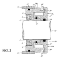
- FIG. 2 is a sectional view of the present invention as shown in FIG. 1 .
- FIG. 3 is a sectional view of another embodiment of the present invention as shown in FIG. 2 wherein a conduction ring is shown with a plurality of conductive brushes.
- FIG. 4 is a sectional view of another embodiment of the present invention wherein a metallic conduction ring is shown with an insert having conductive properties.
- FIG. 5 is a sectional view of another embodiment as shown in FIG. 2 wherein the conductive ring is solid.
- FIG. 6 is another embodiment of the present invention as shown in FIG. 2 .
- FIG. 7 is a side view of the present invention illustrating the concentric nature of the invention.
- FIG. 1 illustrates a perspective view of the motor ground seal assembly 18 applied to a rotatable shaft 10 of an electrical motor (not shown) having a variable frequency drive (VFD).
- the motor grounding SealTM assembly 18 shown in FIG. 1 may be mounted to rotatable shaft 10 on either one or both sides of the motor housing assembly 11 .
- the motor grounding SealTM assembly 18 may be flange-mounted, press-fit, or attached by other means to a housing 11 .
- the motor ground seal assembly 18 will also function with a rotating housing and stationary shaft (not shown).
- the receptor groove 4 allows placement of one of the following conductive inserts with the motor grounding seal assembly 18 : a solid conductive ring having conductive filament brushes 3 attached therein, a solid conductive ring having conductive filament brushes 3 attached therein and a metallic annular frame surrounding the conductive ring, a metallic insert with solid conductor ring 6 , or a conductive insert ring 7 .
- the receptor groove 4 as-shown can also be utilized on other shaft seal assemblies and bearing isolators or combinations therein which use only labyrinths.
- the location of the gap with respect to the rotor 13 and stator 14 surfaces and the direction of the opening interface gaps 20 and 21 are both important elements of one embodiment of the motor grounding seal assembly 18 .
- the rotor 13 extends radially well beyond the major diameter of the stator 14 . This permits the rotor 13 to encompass the also radially extended projection 19 of the stator 14 . It is important that this radial extension of the rotor 13 extends beyond the basic radial dimension of stator 14 . See U.S. Pat. No. 6,419,233 issued to Orlowski and incorporated by reference herein. This requires a departure from the prior art wherein the rotor 13 was radially co-extensive with the major diameter of the stator 14 .
- the second radial interface gap 21 between the rotor 13 and stator 14 that is exposed to the contamination or lubricants is now fixed in dimension and independent of any relative axial movement between the rotor 13 and the stator 14 .
- the first radial interface gap 20 is still subject to variation in dimension by any relative axial movement between the rotor 13 and the stator 14 .
- the orientation of the opening of the interface gap 21 is important regardless of relative movement between the rotor 14 and stator 13 .
- the axial orientation of the second radial interface gap 21 controls entrance of contaminants. Reduction or elimination of contaminants improves both the life and performance of the conductive means.
- the opening of the second radial interface gap 21 is now facing rearward toward the housing 11 and away from the contaminant stream. The contaminant or cooling stream will normally be directed along the axis of the shaft 10 and toward the housing 11 .
- a first stator groove 22 may be cut in the stator 14 .
- This stator groove 22 enhances and accentuates the benefits of the radial extension of the rotor 13 and the stator 14 with the resultant orientation and independence of the second radial interface gap 21 .
- the motor ground seal assembly 18 may be made from any machinable metal (such as stainless steel) or a metal having low resistivity, including but not limited to bronze, aluminum, copper, gold, and combinations thereof.
- a second groove may be cut into the stator 14 on the inboard side facing away from the rotor 13 and into the housing 11 .
- This receptor groove 4 allows insertion of a circumferential ring-like structure, sometimes referred to herein as a conductive insert.
- the embodiment illustrated in FIG. 2 shows a solid conductive ring 9 having conductive filaments or brushes 3 in contact with shaft 10 .
- the concentric solid conduction ring 9 may be flange-mounted, press-fit, or attached by other means to and/or within receptor groove 4 .
- FIG. 3 shows another embodiment of the motor ground seal assembly 18 wherein the conductive insert is a brush ring 5 having a metallic base or frame 16 , preferably made from a low resistivity material such as bronze, copper, gold, or aluminum.
- the conductive insert may have a plurality of fibrous conductive brushes 3 engaged with rotatable shaft 10 for transmission of bearing currents to ground.
- the circumference of the brush ring 5 is force-fitted into the receptor groove 4 in the motor ground seal assembly 18 by means of a slightly tapered bore (not shown) in the receptor groove 4 to accommodate imperfections and dimensional tolerance of the brush ring 5 surrounding the filament brushes 3 .
- the brush ring 5 may be as described in published U.S. Pat. Nos. 7,193,836 and 7,528,513.
- the brush ring 5 would incorporate technology sold as an “AEGIS SGRTM Conductive MicroFiberTM brush” by Electro Static Technology—an Illinois Tool Works Company.
- a preferred embodiment of the motor ground seal assembly 18 is one in which the brush ring 5 is configured such that the conductive brushes 3 are in constant contact with the shaft 10 at all times (i.e., when the shaft 10 is stationary and when the shaft 10 is rotating). This is due at least in part to the potential for brush ring frame 16 deformation, as described below.
- the motor grounding seal assembly 18 improves conduction and reduces the effects of “bearing current” by enhancing and increasing the rigidity of circumferential brush ring 5 , thereby increasing the resistance to deformation of the brush ring frame 16 during operation.
- Deformation of the brush ring 5 and frame 16 during operation destabilizes the spatial relationship between the tip of the conductive brushes 3 , or the shaft facing surfaces of other conductive means, and the rotating shaft 10 .
- the resulting change in spatial relationship which although small and within normal machine operating tolerances, negatively affects the conduction of the electrostatic discharge (shaft voltage) from the rotating shaft 10 to ground, thus resulting in the decreased performance of prior art grounding devices.
- a motor ground seal assembly 18 configured to ensure this continuous contact includes conductive brushes 3 that are sized to be long enough so as to overcome any windage caused by the rotation of the shaft 10 .
- the performance of the motor ground seal assembly 18 disclosed and claimed herein is further improved by aggressive interference between the conductive insert and receptor groove 4 of the motor ground seal assembly 18 .
- the outside diameter of the brush ring 5 may be up to 0.004 inches (0.102 mm) greater than the inside diameter of the receptor groove 4 .
- the performance of the motor ground seal assembly 18 is further improved by aggressive interference between the motor grounding seal assembly 18 and the housing 11 of the motor.
- the outside diameter of the stator may be up to 0.004 inches (0.102 mm) greater than the inside diameter of the motor housing 11 .
- FIG. 4 shows another embodiment of the motor ground seal assembly 18 wherein the metallic insert with solid conductor ring 6 has a metallic base, preferably a low resistivity material such as bronze, copper, gold, or aluminum, and forms a circumferential conductive ring around the rotating shaft 10 when inserted into the receptor groove 4 of the stator 14 . A portion of the solid conductor ring 6 may then engage the rotatable shaft 10 for transmission of bearing currents to ground.
- a metallic base preferably a low resistivity material such as bronze, copper, gold, or aluminum
- FIG. 5 shows another embodiment of the motor ground seal assembly 18 wherein the conductive insert ring 7 is a concentric circumferential ring affixed within the receptor groove 4 of the stator 14 for engagement with shaft 10 for transmission of bearing currents to ground. Reduction of deformity through an aggressive interference between the conductive insert/receptor groove 4 and motor ground seal assembly 18 /housing 11 is contemplated for the embodiments shown and described at FIGS. 4 and 5 .
- the motor ground seal assembly 18 may be used with an o-ring 17 between stator 14 and motor housing 11 as shown in preceding FIGS. 1-5 . Performance of the motor ground seal assembly 18 , however, may be further improved by eliminating o-ring 17 and its companion groove as shown in FIG. 6 .
- the non-conductive nature of o-ring 17 can impede conductivity between the motor ground seal assembly 18 and motor housing 11 thereby decreasing the overall charge dissipation performance of the motor ground seal assembly 18 .
- the motor ground seal assembly 18 in combination with the motor housing 11 creates a stable concentric system with the rotating shaft 10 as its center point 12 . Inserting the combination of conductive brushes 3 , brush rings 5 , or conductive inserts into the motor ground seal assembly 18 within the motor housing 10 , and press or force fitting the various conducting elements (conductive insert, stator 13 and housing 11 ) together, provides a relatively fixed and stable spatial relationship between the conducting elements, thereby improving the collection and conduction of electrostatic discharge (shaft voltage) from the rotating shaft 10 to ground through the conducting elements of the motor ground seal assembly 18 .
- This improved motor ground sealing system directly seats major elements together, which compensates for motor shafts 10 that are not necessarily perfectly round, and ensures the variation or change in distance from the brush tips 3 to the shaft 10 surface caused by external forces acting on the motor ground sealing system are minimal, thus promoting effective conduction of shaft voltage.
Abstract
A shaft seal assembly is disclosed having a stator including a main body and axial and radial projections therefrom. The rotor may be radially extended to encompass the axial and radial projections from said stator. A passageway formed between the radial projection of stator and rotor results in an axial passageway having its opening facing rearwardly from the rotor and away from the source of impinging coolant and/or contaminant. A concentric circumferential receptor groove in the stator facing the housing allows insertion of a conductive insert for transmission of electrostatic charge away from the shaft through the shaft seal assembly to the housing and ground. The receptor groove is opposite the axial passageway and provides for both a substantially lower contaminant environment and improved engagement with the conductive insert.
Description
The present application is a continuation of and claims priority from U.S. patent application Ser. No. 14/188,236 filed on Feb. 24, 2014, which application was a continuation of and claimed priority from U.S. patent application Ser. No. 13/855,355 filed on Apr. 2, 2013, which application was a continuation of and claimed priority from U.S. patent application Ser. No. 13/103,805 filed on May 9, 2011 (now abandoned), which application was a continuation-in-part of and claimed priority from U.S. patent application Ser. No. 12/401,331 filed on Mar. 10, 2009 (now abandoned), which application was a continuation of and claimed priority from U.S. patent application Ser. No. 11/378,208 filed on Mar. 17, 2006 (now U.S. Pat. No. 7,521,827), which claimed the benefit of U.S. provisional App. No. 60/693,548, filed Jun. 25, 2005, all of which are incorporated herein in their entireties.
The present invention relates to an improved bearing isolator sealing device, and more particularly, to a bearing isolator for directing electrostatic charge to ground while retaining lubrication solution and repelling contamination such as water, dust, dirt, sand and paper stock from the bearing environment and away from the shaft grounding ring, within the bearing cavity of a hub assembly such as an electrical motor bearing for engagement with a rotatable shaft.
No federal funds were used to develop or create the invention disclosed and described in the patent application.
(Not Applicable)
This invention relates generally to shaft sealing devices for use with rotating equipment. Adequate maintenance of rotating equipment is difficult to obtain because of extreme equipment duty cycles, the lessening of service factors, design, and the lack of spare rotating equipment in most processing plants. This is especially true of machine tool spindles, wet-end paper machine rolls, aluminum rolling mills, and steam quench pumps and other equipment utilizing extreme contamination affecting lubrication. Various forms of shaft sealing devices have been utilized to try to protect the integrity of the bearing environment, including rubber lip seals, clearance labyrinth seals, and attraction magnetic seals. Lip seals or other contacting shaft seals can quickly wear to failure and are also known to permit excessive amounts of moisture and other contaminants to immigrate into the oil reservoir of the operating equipment before seal failure had exposed the interface between the rotor and the stator to the contaminants or lubricants at the radial extremity of the seal. The problem of seal wear and damage as applied to electrical motors using variable frequency drives is compounded because of the very nature of the control of electricity connected to variable frequency drive (VFD) controlled motors.
VFDs regulate the speed of a motor by converting sinusoidal line alternating current (AC) voltage to direct current (DC) voltage, then back to a pulse width modulated (PWM) AC voltage of variable frequency. The switching frequency of these pulses ranges from 1 kHz up to 20 kHz and is referred to as the “carrier frequency.” The ratio of change in voltage to the change in time (AV/AT) creates what has been described as a parasitic capacitance between the motor stator and the rotor, which induces a voltage on the rotor shaft. If the voltage induced on the shaft, which is referred to as “common mode voltage” or “shaft voltage,” builds up to a sufficient level, it can discharge to ground through the bearings. Current that finds its way to ground through the motor bearings in this manner is called “bearing current.”1 1 http://www.greenheck.com/technical/tech_detail.php?display=files/Product_guide/fa117_03
There are many causes of bearing current including voltage pulse overshoot in the VFD, non-symmetry of the motor's magnetic circuit, supply imbalances, and transient conditions, among other causes. Any of these conditions can occur independently or simultaneously to create bearing currents in the motor shaft.2 2 http://www.greenheck.com/technical/tech_detail.php?display=files/Product_guide/fa117_03
Shaft voltage accumulates on the rotor until it exceeds the dielectric capacity of the motor bearing lubricant, then the voltage discharges in a short pulse to ground through the bearing. After discharge, the voltage again accumulates on the shaft and the cycle repeats itself. This random and frequent discharging has an electric discharge machining (EDM) effect, causing pitting of the bearing's rolling elements and raceways. Initially, these discharges create a “frosted” or “sandblasted” effect. Over time, this deterioration causes a groove pattern in the bearing race called “fluting,” which is an indication that the bearing has sustained severe damage. Eventually, the deterioration will lead to complete bearing failure.3 3 See www.Greenheck.com
The prior art teaches numerous methods of mitigating the damage shaft voltages cause, including using a shielded cable, grounding the shaft, insulated bearings, and installation of a Faraday shield. For example, U.S. Pat. No. 7,193,836 discloses devices for controlling shaft current, which devices are designed to induce ionization in the presence of an electrical field.
Most external applications add to costs, complexity, and exposure to external environmental factors. Insulated bearings provide an internal solution by eliminating the path to ground through the bearing for current to flow. However, installing insulated bearings does not eliminate the shaft voltage, which will still find the lowest impedance path to ground. Thus, insulated bearings are not effective if the impedance path is through the driven load. Therefore, the prior art does not teach an internal, low wearing method or apparatus to efficaciously ground shaft voltage and avoid electric discharge machining of bearings leading to premature bearing failure.
An objective of the motor grounding seal is to provide an improvement to seals or bearing isolators to prevent leakage of lubricant and entry of contaminants by encompassing the stator within the rotor to create an axially directed interface at the radial extremity of the rotor. It is also an objective of the present invention to disclose and claim a seal or bearing isolator for rotating equipment that retains lubricants, prevents contamination and conducts and transmits and directs accumulated bearing current to ground.
Placement of a receptor groove in the stator of a shaft seal assembly allows insertion of a conductive insert in the stator. Although such a conductive insert may be constructed of any type of metal compatible with operating conditions and metallurgy, bronze, gold, or aluminum are believed to be preferred metals because of increased conductivity, strength, and resistance to corrosion and wear. Combining the receptor groove and conductive insert with the benefits of the improved bearing isolator reduces the environmental exposure of the conductive insert.
It has been found that a bearing isolator assembly having a rotor and stator manufactured from bronze has improved charge dissipation qualities. The preferred bronze metallurgy is that meeting specification 932 (also referred to as 932000 or “bearing bronze”). This bronze is preferred for bearings and bearing isolators because it has excellent load capacity and antifriction qualities. This bearing bronze alloy also has good machining characteristics and resists many chemicals. It is believed that the specified bronze offers increased shaft voltage collection properties comparable to the ubiquitous lighting rod due to the relatively low electrical resistivity (85.9 ohms-cmil/ft @ 68 F or 14.29 micro-ohm-cm @ 20 C) and high electrical conductivity (12% IACS @ 68 F or 0.07 MegaSiemens/cm @ 20 C) of the material selected.
Previous tests of a combination shaft seal assembly with a concentric inserted conductive brush engaged with the shaft have shown substantial reduction in shaft voltage and attendant electrostatic discharge machining. Direct seating between the conduction ring means and the bearing isolator portion of the motor ground seal improves the conduction to ground over a simple housing in combination with a conduction means as taught by the prior art. Those practiced in the arts will understand that this improvement requires the electric motor base to be grounded, as is the norm.
It is therefore an objective of the motor grounding seal to disclose and claim an electric motor for rotating equipment having a bearing isolator that retains lubricants, prevents contamination, and conducts and transmits and directs bearing current to ground.
It is another objective of the motor grounding seal to disclose and claim a bearing isolator for rotating equipment that retains lubricants, prevents contamination, and conducts electrostatic discharge (shaft voltage) to improve bearing operating life.
It is another objective of the motor grounding seal to disclose and claim a bearing isolator for rotating equipment that retains lubricants, prevents contamination, and provides adequate grounding.
It is another objective of the motor grounding seal to disclose and claim a bearing isolator for rotating equipment that retains lubricants, prevents contamination, and provides a low impedance ground path for the voltage to flow to earth ground without passing through the motor bearings or other components while protecting and isolating the conductive insert from the elements.
Other objects, advantages, and embodiments of the motor grounding seal will become apparent upon the reading the following detailed description and upon reference to drawings.
| DETAILED DESCRIPTION ELEMENT LISTING |
| Description | Element No. | ||
| Drive bearing | 2 | ||
| Conductive brushes | 3 | ||
| |
4 | ||
| |
5 | ||
| Metallic insert with |
6 | ||
| Conductive insert ring | 7 | ||
| O- |
8 | ||
| Solid |
9 | ||
| |
10 | ||
| |
11 | ||
| |
12 | ||
| |
13 | ||
| | 13a | ||
| Stator | |||
| 14 | |||
| Stator surface | 14a | ||
| O- |
15 | ||
| Brush ring frame | 16 | ||
| O-ring | 17 | ||
| Motor |
18 | ||
| Radial projection | 19 | ||
| First |
20 | ||
| Second |
21 | ||
| |
22 | ||
As shown in FIGS. 2-6 , the rotor 13 faces outboard and is engaged with an inboard facing stator 14. The receptor groove 4 allows placement of one of the following conductive inserts with the motor grounding seal assembly 18: a solid conductive ring having conductive filament brushes 3 attached therein, a solid conductive ring having conductive filament brushes 3 attached therein and a metallic annular frame surrounding the conductive ring, a metallic insert with solid conductor ring 6, or a conductive insert ring 7. The receptor groove 4 as-shown can also be utilized on other shaft seal assemblies and bearing isolators or combinations therein which use only labyrinths.
As shown in FIGS. 2-6 , the location of the gap with respect to the rotor 13 and stator 14 surfaces and the direction of the opening interface gaps 20 and 21 are both important elements of one embodiment of the motor grounding seal assembly 18. The rotor 13 extends radially well beyond the major diameter of the stator 14. This permits the rotor 13 to encompass the also radially extended projection 19 of the stator 14. It is important that this radial extension of the rotor 13 extends beyond the basic radial dimension of stator 14. See U.S. Pat. No. 6,419,233 issued to Orlowski and incorporated by reference herein. This requires a departure from the prior art wherein the rotor 13 was radially co-extensive with the major diameter of the stator 14.
The second radial interface gap 21 between the rotor 13 and stator 14 that is exposed to the contamination or lubricants is now fixed in dimension and independent of any relative axial movement between the rotor 13 and the stator 14. The first radial interface gap 20 is still subject to variation in dimension by any relative axial movement between the rotor 13 and the stator 14.
This relative movement is not significant to the operation in as much as only a small amount of contaminants have been able to enter the labyrinth because of the size and location of the first radial interface gap 20. The removal of the interface gap 21 from variations is more important in seals where the stator 13 and the rotor 14 are not restrained from relative movement.
The orientation of the opening of the interface gap 21 is important regardless of relative movement between the rotor 14 and stator 13. The axial orientation of the second radial interface gap 21 controls entrance of contaminants. Reduction or elimination of contaminants improves both the life and performance of the conductive means. The opening of the second radial interface gap 21 is now facing rearward toward the housing 11 and away from the contaminant stream. The contaminant or cooling stream will normally be directed along the axis of the shaft 10 and toward the housing 11.
A first stator groove 22 may be cut in the stator 14. This stator groove 22 enhances and accentuates the benefits of the radial extension of the rotor 13 and the stator 14 with the resultant orientation and independence of the second radial interface gap 21. The motor ground seal assembly 18 may be made from any machinable metal (such as stainless steel) or a metal having low resistivity, including but not limited to bronze, aluminum, copper, gold, and combinations thereof.
A second groove may be cut into the stator 14 on the inboard side facing away from the rotor 13 and into the housing 11. This receptor groove 4 allows insertion of a circumferential ring-like structure, sometimes referred to herein as a conductive insert. The embodiment illustrated in FIG. 2 shows a solid conductive ring 9 having conductive filaments or brushes 3 in contact with shaft 10. The concentric solid conduction ring 9 may be flange-mounted, press-fit, or attached by other means to and/or within receptor groove 4.
In one embodiment of the motor ground seal assembly 18, the brush ring 5 may be as described in published U.S. Pat. Nos. 7,193,836 and 7,528,513. In such an embodiment, the brush ring 5 would incorporate technology sold as an “AEGIS SGR™ Conductive MicroFiber™ brush” by Electro Static Technology—an Illinois Tool Works Company. However, such an embodiment is not preferred. Instead, a preferred embodiment of the motor ground seal assembly 18 is one in which the brush ring 5 is configured such that the conductive brushes 3 are in constant contact with the shaft 10 at all times (i.e., when the shaft 10 is stationary and when the shaft 10 is rotating). This is due at least in part to the potential for brush ring frame 16 deformation, as described below.
The motor grounding seal assembly 18 improves conduction and reduces the effects of “bearing current” by enhancing and increasing the rigidity of circumferential brush ring 5, thereby increasing the resistance to deformation of the brush ring frame 16 during operation. Deformation of the brush ring 5 and frame 16 during operation destabilizes the spatial relationship between the tip of the conductive brushes 3, or the shaft facing surfaces of other conductive means, and the rotating shaft 10. The resulting change in spatial relationship, which although small and within normal machine operating tolerances, negatively affects the conduction of the electrostatic discharge (shaft voltage) from the rotating shaft 10 to ground, thus resulting in the decreased performance of prior art grounding devices.
Ensuring continuous contact between the conductive brushes 3 and the shaft 10 both when the shaft 10 is rotating and when it is stationary prevents decreased performance caused by brush ring 5 deformation. Accordingly, conduction of static charges from the shaft 10 to the conductive brushes 3 is preferred as opposed to the ionization described in U.S. Pat. No. 7,193,836. One embodiment of a motor ground seal assembly 18 configured to ensure this continuous contact includes conductive brushes 3 that are sized to be long enough so as to overcome any windage caused by the rotation of the shaft 10.
The performance of the motor ground seal assembly 18 disclosed and claimed herein is further improved by aggressive interference between the conductive insert and receptor groove 4 of the motor ground seal assembly 18. The outside diameter of the brush ring 5 may be up to 0.004 inches (0.102 mm) greater than the inside diameter of the receptor groove 4. The performance of the motor ground seal assembly 18 is further improved by aggressive interference between the motor grounding seal assembly 18 and the housing 11 of the motor. The outside diameter of the stator may be up to 0.004 inches (0.102 mm) greater than the inside diameter of the motor housing 11.
The motor ground seal assembly 18 may be used with an o-ring 17 between stator 14 and motor housing 11 as shown in preceding FIGS. 1-5 . Performance of the motor ground seal assembly 18, however, may be further improved by eliminating o-ring 17 and its companion groove as shown in FIG. 6 . The non-conductive nature of o-ring 17 can impede conductivity between the motor ground seal assembly 18 and motor housing 11 thereby decreasing the overall charge dissipation performance of the motor ground seal assembly 18.
As shown in FIG. 7 , the motor ground seal assembly 18 in combination with the motor housing 11 creates a stable concentric system with the rotating shaft 10 as its center point 12. Inserting the combination of conductive brushes 3, brush rings 5, or conductive inserts into the motor ground seal assembly 18 within the motor housing 10, and press or force fitting the various conducting elements (conductive insert, stator 13 and housing 11) together, provides a relatively fixed and stable spatial relationship between the conducting elements, thereby improving the collection and conduction of electrostatic discharge (shaft voltage) from the rotating shaft 10 to ground through the conducting elements of the motor ground seal assembly 18. This improved motor ground sealing system directly seats major elements together, which compensates for motor shafts 10 that are not necessarily perfectly round, and ensures the variation or change in distance from the brush tips 3 to the shaft 10 surface caused by external forces acting on the motor ground sealing system are minimal, thus promoting effective conduction of shaft voltage.
Having described the preferred embodiment, other features of the present invention will undoubtedly occur to those versed in the art, as will numerous modifications and alterations in the embodiments of the invention illustrated, all of which may be achieved without departing from the spirit and scope of the invention.
Claims (20)
1. A bearing isolator for shaft grounding comprising:
a. a stator surrounding a shaft and affixed to a housing, the stator having a main body and projections extending both axially and radially beyond the main body;
b. a rotor surrounding the shaft, the rotor secured to the shaft, the rotor having a main body and projections extending both radially and axially;
c. a circumferential receptor groove formed in the stator, wherein the receptor groove faces the shaft; and
d. a circumferential conductive insert, the conductive insert placed within the receptor groove and engaged with the shaft to conduct electrical currents away from the shaft to the housing, wherein the rotor and the stator are abutted and intermeshed with each other on the shaft, the rotor radial projections extending radially outwardly farther than any radial projections of the stator.
2. The bearing isolator for shaft grounding in accordance with claim 1 wherein the radial space between the radial rotor projections and the radial stator projections forms a first axial passage.
3. The bearing isolator for shaft grounding in accordance with claim 2 , wherein the first passageway includes a first axial passage opening to a space in the stator and facing the body of the stator between the housing and the radial extensions of the rotor and the stator.
4. The bearing isolator for shaft grounding in accordance with claim 2 , wherein the main body of the stator surrounds a portion of the rotor.
5. The bearing isolator for shaft grounding in accordance with claim 2 , wherein the radius of the radial internal surface of the rotor radial projection encompassing the stator is greater than the radius of the exterior surface of the radial projection of the stator.
6. The bearing isolator for shaft grounding in accordance with claim 1 , wherein there is at least one labyrinth formed between the main body of the stator and the main body of the rotor.
7. The bearing isolator for shaft grounding in accordance with claim 1 , wherein a groove is formed in the main body of the stator, the groove augmenting the radial extension of the radial projection from the stator.
8. The bearing isolator for shaft grounding in accordance with claim 1 wherein the circumferential conductive insert is further defined as having a plurality of conductive brushes extending therefrom toward the shaft, and wherein the plurality of conductive brushes are in contact with the shaft.
9. The bearing isolator for shaft grounding in accordance with claim 2 wherein a groove is formed in the main body of the stator, the groove augmenting the radial extension of the radial projection from the stator.
10. The bearing isolator for shaft grounding in accordance with claim 1 wherein a portion of the stator surrounds a portion of the rotor.
11. A method for extending the life of a bearing comprising:
a. isolating the bearing from an external environment using a bearing isolator, wherein said bearing isolator is secured to a housing at a stator of said bearing isolator, wherein said bearing is positioned within said housing, wherein said housing is electrically grounded, wherein a shaft protrudes from said housing, and wherein said shaft is rotatable with respect to said housing;
b. securing a rotor of said bearing isolator to said shaft, wherein said stator and said rotor are formed with a plurality of corresponding grooves and projections such that said stator and rotor are abutted and intermeshed with one another to form a labyrinth seal during use; and
c. providing a path to ground from said shaft through said bearing isolator, wherein said path passes from said housing to said stator, from said stator to a conductive insert secured to said stator, and from said conductive insert to said shaft.
12. The method according to claim 11 wherein said conductive insert is further defined as being positioned in a receptor groove fashioned in said stator.
13. The method according to claim 11 wherein said conductive insert is further defined as having a plurality of conductive brushes extending therefrom toward said shaft, and wherein said plurality of conductive brushes are in contact with said shaft.
14. The method according to claim 11 wherein a radial space between a rotor radial projection and a stator radial projection forms a first axial passage.
15. The method according to claim 14 , wherein said first axial passage includes a first axial passage opening to a space in said stator and facing said housing.
16. The method according to claim 15 , wherein a portion of said stator surrounds a portion of said rotor.
17. The method according to claim 11 , wherein a rotor radial projection extends radially beyond any portion of said stator.
18. A bearing isolator providing an electrical path to ground away from the bearing isolator to a housing, the bearing isolator comprising:
a. a stator securable in a housing in which a bearing is located, wherein a rotatable shaft extends from the housing, and wherein the housing is electrically grounded, the stator having a main body with a plurality of projections extending both axially and radially beyond the main body;
b. a rotor securable to the rotatable shaft, the rotor having a main body with a plurality of projections extending both axially and radially beyond the main body, wherein the rotor projections correspond to the stator projections so as to form a labyrinth seal between the stator and the rotor; and
c. a conductive insert secured within the stator, wherein the conductive insert provides an electrical path to ground from the shaft to the conductive insert, from the conductive insert to the stator, and from the stator to the housing.
19. The bearing isolator providing an electrical path to ground away from the bearing isolator to a housing according to claim 18 wherein the conductive insert is further defined as having a plurality of conductive brushes extending therefrom toward the shaft, and wherein the plurality of conductive brushes are in contact with the shaft.
20. The bearing isolator providing an electrical path to ground away from the bearing isolator to a housing according to claim 18 , wherein a portion of the stator surrounds a portion of the rotor.
Priority Applications (1)
| Application Number | Priority Date | Filing Date | Title |
|---|---|---|---|
| US15/464,340 US10270320B1 (en) | 2005-06-25 | 2017-03-21 | Motor grounding seal |
Applications Claiming Priority (7)
| Application Number | Priority Date | Filing Date | Title |
|---|---|---|---|
| US69354805P | 2005-06-25 | 2005-06-25 | |
| US11/378,208 US7521827B2 (en) | 2005-06-25 | 2006-03-17 | Motor ground seal |
| US12/401,331 US20110101618A1 (en) | 2005-06-25 | 2009-03-10 | Motor Grounding Seal |
| US13/103,805 US20110204734A1 (en) | 2005-06-25 | 2011-05-09 | Motor Grounding Seal |
| US201313855355A | 2013-04-02 | 2013-04-02 | |
| US14/188,236 US9634547B1 (en) | 2005-06-25 | 2014-02-24 | Motor grounding seal |
| US15/464,340 US10270320B1 (en) | 2005-06-25 | 2017-03-21 | Motor grounding seal |
Related Parent Applications (1)
| Application Number | Title | Priority Date | Filing Date |
|---|---|---|---|
| US14/188,236 Continuation US9634547B1 (en) | 2005-06-25 | 2014-02-24 | Motor grounding seal |
Publications (1)
| Publication Number | Publication Date |
|---|---|
| US10270320B1 true US10270320B1 (en) | 2019-04-23 |
Family
ID=44475911
Family Applications (3)
| Application Number | Title | Priority Date | Filing Date |
|---|---|---|---|
| US13/103,805 Abandoned US20110204734A1 (en) | 2005-06-25 | 2011-05-09 | Motor Grounding Seal |
| US14/188,236 Active 2027-05-29 US9634547B1 (en) | 2005-06-25 | 2014-02-24 | Motor grounding seal |
| US15/464,340 Active 2026-05-26 US10270320B1 (en) | 2005-06-25 | 2017-03-21 | Motor grounding seal |
Family Applications Before (2)
| Application Number | Title | Priority Date | Filing Date |
|---|---|---|---|
| US13/103,805 Abandoned US20110204734A1 (en) | 2005-06-25 | 2011-05-09 | Motor Grounding Seal |
| US14/188,236 Active 2027-05-29 US9634547B1 (en) | 2005-06-25 | 2014-02-24 | Motor grounding seal |
Country Status (1)
| Country | Link |
|---|---|
| US (3) | US20110204734A1 (en) |
Cited By (1)
| Publication number | Priority date | Publication date | Assignee | Title |
|---|---|---|---|---|
| USD980069S1 (en) | 2020-07-14 | 2023-03-07 | Ball Corporation | Metallic dispensing lid |
Families Citing this family (24)
| Publication number | Priority date | Publication date | Assignee | Title |
|---|---|---|---|---|
| US20110204734A1 (en) * | 2005-06-25 | 2011-08-25 | Orlowski David C | Motor Grounding Seal |
| JP5704002B2 (en) * | 2011-07-13 | 2015-04-22 | 株式会社Ihi | Electric motor |
| US9831739B2 (en) | 2012-06-18 | 2017-11-28 | Inpro/Seal Llc | Explosion-proof current diverting device |
| GB2517452B (en) * | 2013-08-20 | 2015-09-09 | Aes Eng Ltd | Bearing isolator |
| EP3092427B1 (en) * | 2014-01-10 | 2018-03-14 | Flowserve Management Company | Bearing isolator seal for rotating shaft |
| DE102014110602A1 (en) * | 2014-02-28 | 2015-09-03 | Johnson Electric Germany GmbH & Co. KG | Device with a moving component |
| JP2015195668A (en) * | 2014-03-31 | 2015-11-05 | ファナック株式会社 | Electric motor including seal member and manufacturing method of the same |
| US10230290B2 (en) * | 2014-09-08 | 2019-03-12 | Regal Beloit America, Inc. | Electrical machine and methods of assembling the same |
| US9985494B2 (en) | 2014-09-08 | 2018-05-29 | Regal Beloit America, Inc. | Electrical machine and controller and methods of assembling the same |
| US9982674B2 (en) | 2014-09-08 | 2018-05-29 | Regal Beloit America, Inc. | Electrical machine and methods of assembling the same |
| CA2969705C (en) | 2014-12-08 | 2020-06-23 | Flowserve Management Company | Bearing isolator seal with tapered static shutoff o-ring interface |
| WO2016100771A1 (en) * | 2014-12-18 | 2016-06-23 | Flowserve Management Company | Bearing isolator seal with enhanced rotor drive coupling |
| US10644575B2 (en) | 2014-12-19 | 2020-05-05 | Weg Equipamentos Eletricos S.A. | System for grounding bearings of rotary electric machines, and corresponding electric machine |
| US10008909B2 (en) * | 2015-04-24 | 2018-06-26 | Asmo Co., Ltd. | Motor driving control device for vehicle |
| JP6127308B2 (en) * | 2015-05-01 | 2017-05-17 | 株式会社明電舎 | Rotating machine |
| GB201509927D0 (en) * | 2015-06-08 | 2015-07-22 | Aes Eng Ltd | Electrical grounding - labyrinth bearing protector |
| GB201519362D0 (en) * | 2015-11-02 | 2015-12-16 | Aes Eng Ltd | Electrical grounding of bearing seal |
| DE102016010926A1 (en) * | 2016-03-03 | 2017-09-07 | Kaco Gmbh + Co. Kg | Shaft grounding ring |
| DE102016216909A1 (en) * | 2016-09-06 | 2018-03-08 | Bayerische Motoren Werke Aktiengesellschaft | Drive device for a motor vehicle, in particular a motor vehicle, and motor vehicle with such a drive device |
| US10753478B2 (en) * | 2016-11-07 | 2020-08-25 | Garlock Sealing Technologies, Llc | Bearing isolator for extreme conditions |
| CN108566017A (en) * | 2018-06-30 | 2018-09-21 | 中山大洋电机股份有限公司 | A kind of motor effectivelying prevent shaft current ablation bearing |
| DE102018219779A1 (en) * | 2018-11-19 | 2020-05-20 | Zf Friedrichshafen Ag | Sealing device, electric machine and drive device |
| US11754186B2 (en) | 2020-11-17 | 2023-09-12 | Rolls-Royce North American Technologies, Inc. | Grounding brush seals |
| JP2022136835A (en) * | 2021-03-08 | 2022-09-21 | 日本電産株式会社 | Rotary electric machine and driving device |
Citations (62)
| Publication number | Priority date | Publication date | Assignee | Title |
|---|---|---|---|---|
| US2269614A (en) | 1938-07-30 | 1942-01-13 | Zahnradfabrik Friedrichshafen | Sliding current collector for slip rings |
| US3286069A (en) | 1965-08-12 | 1966-11-15 | Kendick Mfg Company | Rotary electrical contact assembly |
| US3785049A (en) | 1970-05-15 | 1974-01-15 | Hitachi Ltd | Slip ring assembly and method of making same |
| US3997224A (en) | 1973-12-26 | 1976-12-14 | Nissan Motor Co., Ltd. | Electrical contacting device |
| US4189702A (en) | 1978-09-25 | 1980-02-19 | Lowrance Electronics, Inc. | Commutator and fiber brush rotating disc |
| US4246508A (en) | 1978-12-22 | 1981-01-20 | Skil Corporation | Brush holder assemblies for small electric motors |
| US4347456A (en) | 1977-10-03 | 1982-08-31 | Etat Francais | Sliding electrical contact devices |
| US4403164A (en) | 1981-01-15 | 1983-09-06 | Lucas Industries Limited | Sliding contact assemblies for rotary electric machines |
| US4483574A (en) | 1979-11-08 | 1984-11-20 | Etat Francais | Sliding electrical contacts for electric machinery |
| US4515417A (en) | 1982-11-24 | 1985-05-07 | Mitsubishi Denki Kabushiki Kaisha | Grounding device for preventing electrolytic corrosion in the bearings of rotary electric machines |
| US4575102A (en) | 1984-11-20 | 1986-03-11 | Ferrofluidics Corporation | Coaxial, multiple-shaft ferrofluid seal apparatus |
| US4685021A (en) | 1986-03-20 | 1987-08-04 | Juri Kortschinski | Fault current diverter |
| EP0291295A2 (en) | 1987-05-13 | 1988-11-17 | Viggo Elris | Electrical generator system |
| US4801270A (en) | 1987-10-05 | 1989-01-31 | Xerox Corporation | Shaft mounting and electrical grounding device |
| US4823039A (en) | 1985-12-18 | 1989-04-18 | Cedric Lynch | Electrical machines |
| US4831295A (en) * | 1986-11-19 | 1989-05-16 | Asea Brown Boveri Ag | Arrangement for reducing shaft voltages in dynamoelectric machines |
| US4850881A (en) | 1986-09-23 | 1989-07-25 | Jaeger | Electrical transmission ring assembly disposed between the steering column and the steering wheel of an automobile vehicle |
| US4855631A (en) | 1987-05-29 | 1989-08-08 | Mitsuba Electric Manufacturing Co., Ltd. | Brush holding device |
| US4954084A (en) * | 1989-09-06 | 1990-09-04 | Marine Hardware, Inc. | Shaft-grounding stuffing box cover |
| US5010441A (en) | 1990-01-24 | 1991-04-23 | Xerox Corporation | Grounding brush |
| JPH0928053A (en) | 1995-07-12 | 1997-01-28 | Okuma Mach Works Ltd | Sealing structure for motor |
| KR970004226B1 (en) | 1990-12-07 | 1997-03-26 | 로움 카부시키가이샤 | Lead mounting apparatus |
| US5661356A (en) * | 1993-10-22 | 1997-08-26 | Fisher; Rodney R. | Motor shaft discharge device |
| WO1998005890A1 (en) | 1996-08-05 | 1998-02-12 | A.W. Chesterton Co. | Seal/bearing assembly |
| US5799905A (en) | 1996-02-13 | 1998-09-01 | Rokita; Stephen R. | Apparatus and method for attaching gutters to structures |
| US5804903A (en) * | 1993-10-22 | 1998-09-08 | Fisher; Rodney R. | Motor shaft discharge device |
| US5812908A (en) | 1997-03-25 | 1998-09-22 | Xerox Corporation | Carbon fiber electrical contact mounting for rotating elements |
| US5912516A (en) | 1997-04-02 | 1999-06-15 | Aisin Seiki Kabushiki Kaisha | High speed alternator/motor |
| JPH11201264A (en) | 1998-01-08 | 1999-07-27 | Central Japan Railway Co | Shaft sealing device of gear device for rolling stock |
| US5967524A (en) | 1993-05-21 | 1999-10-19 | Jm Clipper Corporation | Hybrid seal device |
| US5988996A (en) | 1997-11-05 | 1999-11-23 | Baker Hughes Incorporated | Electrical shaft grounding brush assembly and holder for a submersible pump motor |
| US6145843A (en) | 1998-10-19 | 2000-11-14 | Stein Seal Company | Hydrodynamic lift seal for use with compressible fluids |
| US20010017495A1 (en) | 2000-02-29 | 2001-08-30 | Toshihiro Sato | Motor having shaft-grounding arrangement |
| US20010040099A1 (en) | 1999-08-31 | 2001-11-15 | Pedersen John M. | Method and apparatus for providing electrical and fluid communication to a rotating microelectronic workpiece during electrochemical processing |
| US6386546B1 (en) | 1993-05-21 | 2002-05-14 | Jm Clipper Corporation | Seal cartridge |
| US6390477B1 (en) | 1999-10-14 | 2002-05-21 | Garlock Inc | Rotary shaft bearing isolator seal |
| US6419233B2 (en) | 1998-08-25 | 2002-07-16 | Isotech Of Illinois, Inc. | Shaft seal assembly |
| US20020121821A1 (en) | 2001-03-02 | 2002-09-05 | Ritter Allen Michael | Method and apparatus for reducing bearing current in a motor and/or generator |
| US20020136161A1 (en) | 1999-09-28 | 2002-09-26 | Cleereman Douglas P. | Grounded isolation system |
| US6530694B2 (en) * | 2000-04-20 | 2003-03-11 | Nsk Ltd. | Rolling bearing unit |
| US20030057783A1 (en) | 2001-09-27 | 2003-03-27 | Melfi Michael J. | System and method of reducing bearing voltage |
| US20030086630A1 (en) | 2001-11-06 | 2003-05-08 | Illinois Tool Works, Inc. | Method and system for reducing bearing fluting in electromechanical machine |
| US20030235354A1 (en) | 2002-06-21 | 2003-12-25 | Orlowski David C. | Articulated seal |
| JP2004040926A (en) | 2002-07-04 | 2004-02-05 | Minebea Co Ltd | Fan motor |
| US20040233592A1 (en) | 2003-03-17 | 2004-11-25 | Oh Hieyoung W. | Grounding brush for mitigating electrical current on motor shafts |
| US20050077791A1 (en) * | 2003-10-08 | 2005-04-14 | Wasson Dewain L. | Member for reducing leakage current through a bearing of an electric motor |
| US6913265B2 (en) | 2000-08-09 | 2005-07-05 | Advanced Components & Materials, Inc. | Brush seal assembly, method of manufacture and use |
| US6955473B2 (en) | 2001-11-07 | 2005-10-18 | ZF Lemförder Metallwaren AG | Bushing joint |
| US6972052B2 (en) | 2002-08-28 | 2005-12-06 | Behr Systems, Inc. | Rotational atomizer with external heating system |
| US6984906B1 (en) | 2000-07-13 | 2006-01-10 | General Electric Company | Bearing current reduction assembly |
| US20060007609A1 (en) | 2003-03-17 | 2006-01-12 | Oh Hieyoung W | Shaft current control brush ring assembly |
| US7136271B2 (en) | 2003-03-17 | 2006-11-14 | Illinois Tool Works Inc | Static charge neutralizing assembly for use on rollers and shafts |
| US20070040459A1 (en) * | 2005-08-17 | 2007-02-22 | Oh Hieyoung W | Shaft current control brush assembly with drainage |
| US20070159017A1 (en) | 2006-01-11 | 2007-07-12 | Martin Jerry L | Explosion-proof motor with integrated sensor/lead housing |
| US20070241514A1 (en) | 2002-06-21 | 2007-10-18 | Orlowski David C | Shaft seal assembly |
| EP1967774A1 (en) | 2007-03-05 | 2008-09-10 | Chugai High Technology Co., Ltd. | Coaxial multi-shaft assemblies |
| US7436091B2 (en) * | 2005-06-29 | 2008-10-14 | Detroit Diesel Corporation | Method and system of limiting arcing of rotating member |
| US7521827B2 (en) * | 2005-06-25 | 2009-04-21 | Isotech Of Illinois, Inc. | Motor ground seal |
| US20100127585A1 (en) | 2008-11-24 | 2010-05-27 | Caterpillar Inc. | Grounding mechanism for electric motor |
| US20100176673A1 (en) | 2009-01-14 | 2010-07-15 | Scott Wright | End shield and inner bearing cap assembly |
| US9634547B1 (en) * | 2005-06-25 | 2017-04-25 | Inpro/Seal Llc | Motor grounding seal |
| US9831739B2 (en) * | 2012-06-18 | 2017-11-28 | Inpro/Seal Llc | Explosion-proof current diverting device |
Family Cites Families (1)
| Publication number | Priority date | Publication date | Assignee | Title |
|---|---|---|---|---|
| KR0178154B1 (en) | 1995-06-16 | 1999-05-15 | 정몽원 | Ac generator |
-
2011
- 2011-05-09 US US13/103,805 patent/US20110204734A1/en not_active Abandoned
-
2014
- 2014-02-24 US US14/188,236 patent/US9634547B1/en active Active
-
2017
- 2017-03-21 US US15/464,340 patent/US10270320B1/en active Active
Patent Citations (67)
| Publication number | Priority date | Publication date | Assignee | Title |
|---|---|---|---|---|
| US2269614A (en) | 1938-07-30 | 1942-01-13 | Zahnradfabrik Friedrichshafen | Sliding current collector for slip rings |
| US3286069A (en) | 1965-08-12 | 1966-11-15 | Kendick Mfg Company | Rotary electrical contact assembly |
| US3785049A (en) | 1970-05-15 | 1974-01-15 | Hitachi Ltd | Slip ring assembly and method of making same |
| US3997224A (en) | 1973-12-26 | 1976-12-14 | Nissan Motor Co., Ltd. | Electrical contacting device |
| US4347456A (en) | 1977-10-03 | 1982-08-31 | Etat Francais | Sliding electrical contact devices |
| US4189702A (en) | 1978-09-25 | 1980-02-19 | Lowrance Electronics, Inc. | Commutator and fiber brush rotating disc |
| US4246508A (en) | 1978-12-22 | 1981-01-20 | Skil Corporation | Brush holder assemblies for small electric motors |
| US4483574A (en) | 1979-11-08 | 1984-11-20 | Etat Francais | Sliding electrical contacts for electric machinery |
| US4403164A (en) | 1981-01-15 | 1983-09-06 | Lucas Industries Limited | Sliding contact assemblies for rotary electric machines |
| US4515417A (en) | 1982-11-24 | 1985-05-07 | Mitsubishi Denki Kabushiki Kaisha | Grounding device for preventing electrolytic corrosion in the bearings of rotary electric machines |
| US4575102A (en) | 1984-11-20 | 1986-03-11 | Ferrofluidics Corporation | Coaxial, multiple-shaft ferrofluid seal apparatus |
| US4823039A (en) | 1985-12-18 | 1989-04-18 | Cedric Lynch | Electrical machines |
| US4685021A (en) | 1986-03-20 | 1987-08-04 | Juri Kortschinski | Fault current diverter |
| US4850881A (en) | 1986-09-23 | 1989-07-25 | Jaeger | Electrical transmission ring assembly disposed between the steering column and the steering wheel of an automobile vehicle |
| US4831295A (en) * | 1986-11-19 | 1989-05-16 | Asea Brown Boveri Ag | Arrangement for reducing shaft voltages in dynamoelectric machines |
| EP0291295A2 (en) | 1987-05-13 | 1988-11-17 | Viggo Elris | Electrical generator system |
| US4855631A (en) | 1987-05-29 | 1989-08-08 | Mitsuba Electric Manufacturing Co., Ltd. | Brush holding device |
| US4801270A (en) | 1987-10-05 | 1989-01-31 | Xerox Corporation | Shaft mounting and electrical grounding device |
| US4954084A (en) * | 1989-09-06 | 1990-09-04 | Marine Hardware, Inc. | Shaft-grounding stuffing box cover |
| US5010441A (en) | 1990-01-24 | 1991-04-23 | Xerox Corporation | Grounding brush |
| KR970004226B1 (en) | 1990-12-07 | 1997-03-26 | 로움 카부시키가이샤 | Lead mounting apparatus |
| US5967524A (en) | 1993-05-21 | 1999-10-19 | Jm Clipper Corporation | Hybrid seal device |
| US6386546B1 (en) | 1993-05-21 | 2002-05-14 | Jm Clipper Corporation | Seal cartridge |
| US5661356A (en) * | 1993-10-22 | 1997-08-26 | Fisher; Rodney R. | Motor shaft discharge device |
| US5804903A (en) * | 1993-10-22 | 1998-09-08 | Fisher; Rodney R. | Motor shaft discharge device |
| JPH0928053A (en) | 1995-07-12 | 1997-01-28 | Okuma Mach Works Ltd | Sealing structure for motor |
| US5799905A (en) | 1996-02-13 | 1998-09-01 | Rokita; Stephen R. | Apparatus and method for attaching gutters to structures |
| WO1998005890A1 (en) | 1996-08-05 | 1998-02-12 | A.W. Chesterton Co. | Seal/bearing assembly |
| US5812908A (en) | 1997-03-25 | 1998-09-22 | Xerox Corporation | Carbon fiber electrical contact mounting for rotating elements |
| US5912516A (en) | 1997-04-02 | 1999-06-15 | Aisin Seiki Kabushiki Kaisha | High speed alternator/motor |
| US5988996A (en) | 1997-11-05 | 1999-11-23 | Baker Hughes Incorporated | Electrical shaft grounding brush assembly and holder for a submersible pump motor |
| JPH11201264A (en) | 1998-01-08 | 1999-07-27 | Central Japan Railway Co | Shaft sealing device of gear device for rolling stock |
| US6419233B2 (en) | 1998-08-25 | 2002-07-16 | Isotech Of Illinois, Inc. | Shaft seal assembly |
| US6145843A (en) | 1998-10-19 | 2000-11-14 | Stein Seal Company | Hydrodynamic lift seal for use with compressible fluids |
| US20010040099A1 (en) | 1999-08-31 | 2001-11-15 | Pedersen John M. | Method and apparatus for providing electrical and fluid communication to a rotating microelectronic workpiece during electrochemical processing |
| US20020136161A1 (en) | 1999-09-28 | 2002-09-26 | Cleereman Douglas P. | Grounded isolation system |
| US6390477B1 (en) | 1999-10-14 | 2002-05-21 | Garlock Inc | Rotary shaft bearing isolator seal |
| US20010017495A1 (en) | 2000-02-29 | 2001-08-30 | Toshihiro Sato | Motor having shaft-grounding arrangement |
| US6608410B2 (en) | 2000-02-29 | 2003-08-19 | Asmo Co., Ltd. | Motor having shaft-grounding arrangement |
| US6530694B2 (en) * | 2000-04-20 | 2003-03-11 | Nsk Ltd. | Rolling bearing unit |
| US6984906B1 (en) | 2000-07-13 | 2006-01-10 | General Electric Company | Bearing current reduction assembly |
| US6913265B2 (en) | 2000-08-09 | 2005-07-05 | Advanced Components & Materials, Inc. | Brush seal assembly, method of manufacture and use |
| US20020121821A1 (en) | 2001-03-02 | 2002-09-05 | Ritter Allen Michael | Method and apparatus for reducing bearing current in a motor and/or generator |
| US6670733B2 (en) * | 2001-09-27 | 2003-12-30 | Reliance Electric Technologies, Llc | System and method of reducing bearing voltage |
| US20030057783A1 (en) | 2001-09-27 | 2003-03-27 | Melfi Michael J. | System and method of reducing bearing voltage |
| US20030086630A1 (en) | 2001-11-06 | 2003-05-08 | Illinois Tool Works, Inc. | Method and system for reducing bearing fluting in electromechanical machine |
| US7071589B2 (en) | 2001-11-06 | 2006-07-04 | Precor Incorporated | Method and system for reducing bearing fluting in electromechanical machine |
| US6955473B2 (en) | 2001-11-07 | 2005-10-18 | ZF Lemförder Metallwaren AG | Bushing joint |
| US20030235354A1 (en) | 2002-06-21 | 2003-12-25 | Orlowski David C. | Articulated seal |
| US20070241514A1 (en) | 2002-06-21 | 2007-10-18 | Orlowski David C | Shaft seal assembly |
| US7396017B2 (en) | 2002-06-21 | 2008-07-08 | Isotech Of Illinois, Inc. | Shaft seal assembly |
| JP2004040926A (en) | 2002-07-04 | 2004-02-05 | Minebea Co Ltd | Fan motor |
| US6972052B2 (en) | 2002-08-28 | 2005-12-06 | Behr Systems, Inc. | Rotational atomizer with external heating system |
| US20040233592A1 (en) | 2003-03-17 | 2004-11-25 | Oh Hieyoung W. | Grounding brush for mitigating electrical current on motor shafts |
| US20060007609A1 (en) | 2003-03-17 | 2006-01-12 | Oh Hieyoung W | Shaft current control brush ring assembly |
| US7136271B2 (en) | 2003-03-17 | 2006-11-14 | Illinois Tool Works Inc | Static charge neutralizing assembly for use on rollers and shafts |
| US7193836B2 (en) | 2003-03-17 | 2007-03-20 | Illinois Tool Works Inc | Grounding brush for mitigating electrical current on motor shafts |
| US20050077791A1 (en) * | 2003-10-08 | 2005-04-14 | Wasson Dewain L. | Member for reducing leakage current through a bearing of an electric motor |
| US9634547B1 (en) * | 2005-06-25 | 2017-04-25 | Inpro/Seal Llc | Motor grounding seal |
| US7521827B2 (en) * | 2005-06-25 | 2009-04-21 | Isotech Of Illinois, Inc. | Motor ground seal |
| US7436091B2 (en) * | 2005-06-29 | 2008-10-14 | Detroit Diesel Corporation | Method and system of limiting arcing of rotating member |
| US20070040459A1 (en) * | 2005-08-17 | 2007-02-22 | Oh Hieyoung W | Shaft current control brush assembly with drainage |
| US20070159017A1 (en) | 2006-01-11 | 2007-07-12 | Martin Jerry L | Explosion-proof motor with integrated sensor/lead housing |
| EP1967774A1 (en) | 2007-03-05 | 2008-09-10 | Chugai High Technology Co., Ltd. | Coaxial multi-shaft assemblies |
| US20100127585A1 (en) | 2008-11-24 | 2010-05-27 | Caterpillar Inc. | Grounding mechanism for electric motor |
| US20100176673A1 (en) | 2009-01-14 | 2010-07-15 | Scott Wright | End shield and inner bearing cap assembly |
| US9831739B2 (en) * | 2012-06-18 | 2017-11-28 | Inpro/Seal Llc | Explosion-proof current diverting device |
Non-Patent Citations (1)
| Title |
|---|
| The Intellectual Property Office, Taiwan, Office Action, dated Mar. 14, 2016. |
Cited By (1)
| Publication number | Priority date | Publication date | Assignee | Title |
|---|---|---|---|---|
| USD980069S1 (en) | 2020-07-14 | 2023-03-07 | Ball Corporation | Metallic dispensing lid |
Also Published As
| Publication number | Publication date |
|---|---|
| US20110204734A1 (en) | 2011-08-25 |
| US9634547B1 (en) | 2017-04-25 |
Similar Documents
| Publication | Publication Date | Title |
|---|---|---|
| US10270320B1 (en) | Motor grounding seal | |
| US7521827B2 (en) | Motor ground seal | |
| US20100187946A1 (en) | Current Diverter Ring | |
| US9525327B2 (en) | Current diverter ring | |
| US9614339B2 (en) | Current diverter ring | |
| US5804903A (en) | Motor shaft discharge device | |
| EP1872463B1 (en) | Shaft current control brush ring assembly | |
| EP1755207B1 (en) | Shaft current control brush assembly with drainage | |
| US20080258576A1 (en) | Grounding brush system for mitigating electrical current on rotating shafts | |
| CN111095690A (en) | Method and apparatus for mitigating voltage on rotating shaft | |
| WO2011084723A2 (en) | Electrical bearing ground device | |
| EP1148594B1 (en) | Rolling bearing unit | |
| CN107690746B (en) | Bearing isolator | |
| CN100431226C (en) | Shaft current control brush assembly with drainage | |
| JP2020076427A (en) | Rolling bearing device |
Legal Events
| Date | Code | Title | Description |
|---|---|---|---|
| STCF | Information on status: patent grant |
Free format text: PATENTED CASE |
|
| MAFP | Maintenance fee payment |
Free format text: PAYMENT OF MAINTENANCE FEE, 4TH YEAR, LARGE ENTITY (ORIGINAL EVENT CODE: M1551); ENTITY STATUS OF PATENT OWNER: LARGE ENTITY Year of fee payment: 4 |