EP1148413A2 - Load balancing storage system - Google Patents
Load balancing storage system Download PDFInfo
- Publication number
- EP1148413A2 EP1148413A2 EP01109608A EP01109608A EP1148413A2 EP 1148413 A2 EP1148413 A2 EP 1148413A2 EP 01109608 A EP01109608 A EP 01109608A EP 01109608 A EP01109608 A EP 01109608A EP 1148413 A2 EP1148413 A2 EP 1148413A2
- Authority
- EP
- European Patent Office
- Prior art keywords
- hard disk
- disk drives
- recording media
- group
- loop
- Prior art date
- Legal status (The legal status is an assumption and is not a legal conclusion. Google has not performed a legal analysis and makes no representation as to the accuracy of the status listed.)
- Withdrawn
Links
Images




Classifications
-
- G—PHYSICS
- G06—COMPUTING OR CALCULATING; COUNTING
- G06F—ELECTRIC DIGITAL DATA PROCESSING
- G06F3/00—Input arrangements for transferring data to be processed into a form capable of being handled by the computer; Output arrangements for transferring data from processing unit to output unit, e.g. interface arrangements
- G06F3/06—Digital input from, or digital output to, record carriers, e.g. RAID, emulated record carriers or networked record carriers
- G06F3/0601—Interfaces specially adapted for storage systems
-
- G—PHYSICS
- G06—COMPUTING OR CALCULATING; COUNTING
- G06F—ELECTRIC DIGITAL DATA PROCESSING
- G06F3/00—Input arrangements for transferring data to be processed into a form capable of being handled by the computer; Output arrangements for transferring data from processing unit to output unit, e.g. interface arrangements
- G06F3/06—Digital input from, or digital output to, record carriers, e.g. RAID, emulated record carriers or networked record carriers
- G06F3/0601—Interfaces specially adapted for storage systems
- G06F3/0602—Interfaces specially adapted for storage systems specifically adapted to achieve a particular effect
- G06F3/0604—Improving or facilitating administration, e.g. storage management
- G06F3/0607—Improving or facilitating administration, e.g. storage management by facilitating the process of upgrading existing storage systems, e.g. for improving compatibility between host and storage device
-
- G—PHYSICS
- G06—COMPUTING OR CALCULATING; COUNTING
- G06F—ELECTRIC DIGITAL DATA PROCESSING
- G06F3/00—Input arrangements for transferring data to be processed into a form capable of being handled by the computer; Output arrangements for transferring data from processing unit to output unit, e.g. interface arrangements
- G06F3/06—Digital input from, or digital output to, record carriers, e.g. RAID, emulated record carriers or networked record carriers
- G06F3/0601—Interfaces specially adapted for storage systems
- G06F3/0602—Interfaces specially adapted for storage systems specifically adapted to achieve a particular effect
- G06F3/061—Improving I/O performance
- G06F3/0613—Improving I/O performance in relation to throughput
-
- G—PHYSICS
- G06—COMPUTING OR CALCULATING; COUNTING
- G06F—ELECTRIC DIGITAL DATA PROCESSING
- G06F3/00—Input arrangements for transferring data to be processed into a form capable of being handled by the computer; Output arrangements for transferring data from processing unit to output unit, e.g. interface arrangements
- G06F3/06—Digital input from, or digital output to, record carriers, e.g. RAID, emulated record carriers or networked record carriers
- G06F3/0601—Interfaces specially adapted for storage systems
- G06F3/0602—Interfaces specially adapted for storage systems specifically adapted to achieve a particular effect
- G06F3/0614—Improving the reliability of storage systems
- G06F3/0617—Improving the reliability of storage systems in relation to availability
-
- G—PHYSICS
- G06—COMPUTING OR CALCULATING; COUNTING
- G06F—ELECTRIC DIGITAL DATA PROCESSING
- G06F3/00—Input arrangements for transferring data to be processed into a form capable of being handled by the computer; Output arrangements for transferring data from processing unit to output unit, e.g. interface arrangements
- G06F3/06—Digital input from, or digital output to, record carriers, e.g. RAID, emulated record carriers or networked record carriers
- G06F3/0601—Interfaces specially adapted for storage systems
- G06F3/0628—Interfaces specially adapted for storage systems making use of a particular technique
- G06F3/0629—Configuration or reconfiguration of storage systems
- G06F3/0631—Configuration or reconfiguration of storage systems by allocating resources to storage systems
-
- G—PHYSICS
- G06—COMPUTING OR CALCULATING; COUNTING
- G06F—ELECTRIC DIGITAL DATA PROCESSING
- G06F3/00—Input arrangements for transferring data to be processed into a form capable of being handled by the computer; Output arrangements for transferring data from processing unit to output unit, e.g. interface arrangements
- G06F3/06—Digital input from, or digital output to, record carriers, e.g. RAID, emulated record carriers or networked record carriers
- G06F3/0601—Interfaces specially adapted for storage systems
- G06F3/0628—Interfaces specially adapted for storage systems making use of a particular technique
- G06F3/0629—Configuration or reconfiguration of storage systems
- G06F3/0635—Configuration or reconfiguration of storage systems by changing the path, e.g. traffic rerouting, path reconfiguration
-
- G—PHYSICS
- G06—COMPUTING OR CALCULATING; COUNTING
- G06F—ELECTRIC DIGITAL DATA PROCESSING
- G06F3/00—Input arrangements for transferring data to be processed into a form capable of being handled by the computer; Output arrangements for transferring data from processing unit to output unit, e.g. interface arrangements
- G06F3/06—Digital input from, or digital output to, record carriers, e.g. RAID, emulated record carriers or networked record carriers
- G06F3/0601—Interfaces specially adapted for storage systems
- G06F3/0668—Interfaces specially adapted for storage systems adopting a particular infrastructure
- G06F3/067—Distributed or networked storage systems, e.g. storage area networks [SAN], network attached storage [NAS]
-
- G—PHYSICS
- G06—COMPUTING OR CALCULATING; COUNTING
- G06F—ELECTRIC DIGITAL DATA PROCESSING
- G06F3/00—Input arrangements for transferring data to be processed into a form capable of being handled by the computer; Output arrangements for transferring data from processing unit to output unit, e.g. interface arrangements
- G06F3/06—Digital input from, or digital output to, record carriers, e.g. RAID, emulated record carriers or networked record carriers
- G06F3/0601—Interfaces specially adapted for storage systems
- G06F3/0668—Interfaces specially adapted for storage systems adopting a particular infrastructure
- G06F3/0671—In-line storage system
- G06F3/0683—Plurality of storage devices
- G06F3/0689—Disk arrays, e.g. RAID, JBOD
Definitions
- the present invention relates to a storage system communicated with a host unit, and to the connecting configuration of recording media having the structure of loop connecting plural recording media.
- the loop connection with an optical fiber channel is rapidly spreading as an interface to connect a host unit with devices.
- the structure of the connections between the components inside the disk array unit adopting not the bus but the loop connection with the fiber channel is becoming popular (for example, the structure of the loop connection between the controller and the recording media with the fiber channel).
- Japanese patent publication No. Kokai 11-338646 discloses a disk array unit using not the bus but the switching network structure for the connection between components.
- the recording media As a method of load balancing optimally, it is desirable to mount the recording media to an optimum location considering the loop for the recording medium at the time of mounting the recording medium. In addition, at the time of forming a RAID group with the mounted recording media, it is desirable to select the recording media connected to the optimum loop for the recording media in order to build the RAID group.
- the selection of the mounting location or the selection of the recording media considering the load balancing is difficult for the person other than those who are familiar with the internal structure of controller such as the connecting location of the loop. Even in case an operator who is in charge of the mounting and the setting executes such operation, there is a high possibility that the person fails in distributing the recording media with uniform load.
- the object of the present invention is to provide the recording media mounting system that enables the adequate setting of access paths and load balancing without specifically considering the mounting location.
- the storage system of the present invention consists of two or more recording media storing the data from a host unit, a controller controlling the data transfer between the recording media and the host unit, and plural loops, located between the controller and the recording media, connecting the different recording media among the recording media.
- a recording medium is connected to the adjacent different loop than that of the recording medium and the number of the recording media connected to each loop can be equalized by simply connecting the recording media in turn.
- FIG. 1 is an example of the configuration of the storage system, which uses hard disk drives as the recording medium in accordance with an embodiment of the present invention.
- a loop executing communication and data transfer by connecting the controller with the group of recording media will be referred to as a back-end loop and a loop for connecting with a host unit(s) will be referred to as a front-end loop for description.
- a disk controller 112 is provided with a port 111 which is an interface communicating the disk controller with host units 100-1, 100-2 and 100-3 that are the host units or central processing units through Storage Area Network (SAN), and ports 150 and 151 that are interfaces to connect to back-end loops 140 and 141 respectively for connecting the disk controller with the hard disk drives 120 that are the recording media.
- SAN Storage Area Network
- the disk controller 112 controls the transfer of data written from the host units 100 to the hard disk drives 120 or the transfer of data read from the hard disk drives 120 to the host units 100. In a word, the disk controller 112 controls the whole disk storage subsystem 110.
- This disk storage subsystem 110 consists of the hard disk drives 120-0 through 120-9, connecting bays 130-0 through 130-9 functioning as connectors connecting the hard disk drives detachably with the back-end loops constructed of the fiber channels, the back-end loops 140 and 141 to connect the hard disk drives to the disk controller, and the disk controller 112 controlling the hard disk drives.
- the back-end loops 140 and 141 are electrically connected through the connecting bays 130-0 through 130-9 with the hard disk drives 120-0 through 120-9. It is possible to connect the hard disk drives 120-0 through 120-9 to the connecting bays 130-0 through 130-9 independently and it is not necessary to mount all of the connecting bays with the hard disk drives.
- the disk storage subsystem 110 uses the loop interfaces of the fiber channel for all connections of the back-end loops 140 and 141, the connecting bays 130-0 through 130-9, the hard disk drives 120-0 through 120-9, and the interfaces 150 and 151. It is needless to say that the back-end loops 140 and 141 that are the communication paths are not limited to the fiber channels.
- the back-end loop is illustrated in the figure with the ellipse and with the lines from the ellipse to each of the connecting bays 130.
- each connection is shown by a line for the easiness of description, the connection from the ellipse to the connecting bay 130 also forms a loop which is electrically detachable with the loop indicated by the ellipse.
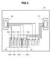
- each of the loops is shown by one line except for the loops in FIG. 3.
- FIG. 3 shows the loop by a pair of lines.
- the port 150 is connected with the back-end loop 140 and the port 151 is connected with the back-end loop 141.
- the connecting bays 130-0, 130-2, 130-4, 130-6 and 130-8 are connected with the back-end loop 140 and the connecting bays 130-1, 130-3, 130-5, 130-7 and 130-9 are connected with the back-end loop 141 respectively.
- the mounting position of each connecting bay alternately connected with each back-end loop is, for example, mounted from the left side sequentially in the order of the consecutive connecting bay number as shown in the figure.
- FIG. 2 shows the outline of the controller 112 of the disk storage subsystem 110.
- the controller 112 comprises a port 111 communicated with a host unit 100 to control the protocol processing and the data transfer with the host unit 100, ports 150 and 151 connected to the hard disk drive group 120 to control the protocol processing and the data transfer with the hard disk drive 120, a cache memory 202 storing the transferred data temporarily, the CPU that is a processor controlling each of these elements and the entire disk controller 112, and a bus 201 used for the data transfer between the ports and the cache memory and for the command transfer between the ports and the CPU.
- the CPU 203 of the disk storage subsystem 110 When the CPU 203 of the disk storage subsystem 110 receives a data write instruction from the host unit 100, the CPU 203 temporarily stores the data sent from the host unit 100 via the port 111 in the cache memory 202 through the bus 201. The CPU 203 reports the end of the write to the host unit when the CPU 203 completes the storage of the data in the cache memory 202. Then, the processor in the port 150 or 151 writes the data stored in the cache memory 202 into the hard disk drive group 120 while being controlled with RAID technology.
- the CPU When the CPU receives the data read instruction from the host unit 100, the CPU refers to the information managing the cache memory and decides whether the instructed data is stored in the cache memory 202. If the instructed data is stored, the CPU transfers the data to the host unit 100 through the port 111. If the data is not stored in the cache memory, the CPU copies the data from the hard disk drives 120 to the cache memory 202, and then transfers the data from the cache memory 202 to the host unit 100 via the port 111.
- the disk controller 112 can be not only bus connected but can connect the cache memory to each interface through independent path.
- the connecting bays 130-0, 130-3, 130-4, 130-7 and 130-8 are connected to the back-end loop 140 and the connecting bays 130-1, 130-2, 130-5, 130-6 and 130-9 are connected to the back-end loop 141 respectively.
- Forming pairs of the hard disk drives 120 except for edge parts can decrease the number of the loops from the back-end loop to the connecting bay.
- the load can be balanced with the connection of the connecting bays 130-0, 130-2, 130-4, 130-6 and 130-8 to the back-end loop 140 and the connection of the connecting bays 130-1, 130-3, 130-5, 130-7 and 130-9 to the back-end loop 141 respectively.
- RAID groups 160 and 161 Four hard disk drives required by the RAID group 160 are allocated from the connecting bay 130-0 in the ascending order. Here, the hard disk drives are allocated alternately to the back-end loops 140 and 141 respectively. Similarly, a pair of required hard disk drives are allocated from the connecting bay 130-4 in the ascending order to the RAID group 161, and then the load is balanced among the back-end loops.
- a simple operation of allocating the required number of the hard disk drives from the connecting bay 130-0 in the ascending order can realize the mounting of the hard disk drives and the load balancing among the back-end loops of the hard disk drives inside the RAID group.
- the components of the disk storage subsystem 110 are the components used in FIG. 1 and the disk storage subsystem 110 is connected with an extension unit 1110 containing back-end loops 142 and 143, connecting bays 131-0 through 131-9, and hard disk drives 121-0 through 121-9.
- the extension unit 1110 is connected with the disk storage subsystem 110 through the connection of the back-end loop 142 with the back-end loop 140 and the back-end loop 143 with the back-end loop 141.
- the figure shows the connection between the back-end loop in the disk storage subsystem 110 and the back-end loop in the extension unit 1110 as the connection of a single line; however, another loop is formed with the back-end loop in the disk storage subsystem 110 and the back-end loop in the extension unit 1110.
- the back-end loop and the connecting bay are connected as follows: the connecting bays 131-0, 131-2, 131-4, 131-6 and 131-8 connect to the back-end loop 142, and the connecting bays 131-1, 131-3, 131-5, 131-7 and 131-9 connect to the back-end loop 143.
- the above-described connection makes it possible to mount or set up the hard disk drives 120 to each connecting bay.
- One RAID group is allocated with twelve of the hard disk drives 120 and the other RAID group is allocated with four of the hard disk drives 120.
- the RAID group is mounted with the necessary twelve hard disk drives from the connection bay 130-0 in the ascending order.
- the mounting of the hard disk drives 120 does not have to start from the connecting bay 130-0 but can start from any other connecting bays 130 sequentially.
- the following describes a configuration of RAID groups 162 and 163.
- the twelve hard disk drives 120 used for the RAID group 162 are sequentially allocated from the connecting bay 130-0 or any mounted connecting bay.
- the sequential allocation from the connecting bays allocates the hard disk drives 120 alternately to the connected group of the back-end loops 140 and 142 and the connected group of the back-end loops 141 and 143; therefore, the load can be balanced between the back-end loops.
- the RAID group 163 can be allocated with the four necessary hard disk drives 120 from the connecting bay 131-2 sequentially to balance the load between the back-end loops.
- a simple rule of sequentially allocating the necessary number of the hard disk drives 120 from the connecting bay 130 can realize the mounting of the hard disk drives 120 and the load balancing among the loops of the hard disk drives inside the RAID group.
- FIG. 5 shows the preferred embodiment of the present invention for a disk storage subsystem provided with three back-end loops.
- the components of the disk storage subsystem 110 are similar to the components of the disk storage subsystem used in FIG. 1. The following is different from the preferred embodiment of FIG. 1: there are three systems in the connection between ports and back-end loops, and between back-end loops and connecting bays.
- Each of the ports 150, 151 and 152 is connected with the back-end loops 140, 141 and 144 respectively, the back-end loop 140 is connected with the connecting bays 130-0, 130-3, 130-6 and 130-9, the back-end loop 141 is connected with the connecting bays 130-1, 130-4 and 130-7 and the back-end loop 144 is connected with the connecting bays 130-2, 130-5 and 130-8.
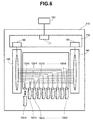
- FIG. 6 shows an example of a storage system provided with plural controllers and loops.
- the data is generally transferred between the back-end loop 140 or 141 and each of the connecting bays 130 through the fiber channel shown with a solid line in FIG. 6. That is, the data transfer under the normal condition is as in the case of FIG. 1.
- the data is transferred through the fiber channel shown with a dotted line using a different back-end loop from the normal one.
- the normal connection route for the hard disk drive 120-1 is from the host unit 100 through the port 111 and the port 151 and via the back-end loop 141 to the connecting bay 130-1; however, in case of a failure between the back-end loop 141 and the connecting bay 130-1, the connection route for the hard disk drive 120-1 will be changed to another route from the host unit 100 through the port 111, the port 150, and the back-end loop 140 to the connecting bay 130-1, so that the data can be transferred without giving the user any influence of the failure.
- the other port and the other back-end loop enable the data transfer between the host unit 100 and the hard disk drive 120.
- the recording medium can be an optical disk or a magneto-optical disk, or can be either of a tape unit or a card type memory such as a flash memory.
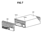
- the above-described disk storage subsystem 110 has, for instance, the external appearance as is shown in FIG. 7.
- the disk storage subsystem 110 has a rectangular frame 301, a front panel 302 with ventilating holes, which is located in front of the disk storage subsystem 110 and covers the front surface, and the connecting bays 130-0 through 130-9 which are arranged in numerical order to mount the hard disk drives 120 on the upper side of the front panel 302. Mounting into these connecting bays 130 allows the hard disk drives to be located in a row of independent ten drives in sequence of 120-0 through 120-9.
- the extension unit 1110 explained in FIG. 4 has the shape of having the connecting bays 131 for mounting the hard disk drives 121 on the upper side of the frame 301, and the back-end loop on the disk array unit 110 can be connected with the back-end loop on the extension unit 1110 on the rear panel shown in FIG. 7.
- the hard disk drives can be easily expanded by stacking the extension unit 1110 and the disk storage subsystem 110.
- stacking the units it is possible to mount the disk storage subsystem 110 and the extension unit 1110 into a rack, or to cover the disk storage subsystem 110 and the extension units 1110 with a frame having a size according to the number of the hard disk drives the user desires.
- the load balancing in each loop and the setting work for the mounting can be facilitated by connecting the back-end loops to the connecting bays which mount the hard disk drives with an adequate pattern so that the connecting bays conform the mounting order of the hard disk drives.
Landscapes
- Engineering & Computer Science (AREA)
- Theoretical Computer Science (AREA)
- Human Computer Interaction (AREA)
- Physics & Mathematics (AREA)
- General Engineering & Computer Science (AREA)
- General Physics & Mathematics (AREA)
- Computer Networks & Wireless Communication (AREA)
- Automatic Disk Changers (AREA)
- Debugging And Monitoring (AREA)
- Automatic Tape Cassette Changers (AREA)
- Control Of Multiple Motors (AREA)
- Information Retrieval, Db Structures And Fs Structures Therefor (AREA)
- Techniques For Improving Reliability Of Storages (AREA)
Abstract
Description
Claims (7)
- A storage system comprising:a controller communicating with a host unit;a first loop connected with said controller and with a first recording medium group recording data from said host unit; anda second loop connected with said controller and with a second recording medium group recording data from said host unit,wherein the recording media of said first recording medium group and the recording media of said second recording medium group are alternately mounted.
- A storage system comprising:a plurality of recording media mounted in juxtaposition;a first loop connected to the (2n-1)th of said recording media (n: natural number);a second loop connected to the (2n)th of said recording media; anda controller connected with said first loop and said second loop and controlling data transfer between each of said recording media and a host unit.
- A storage system comprising:a plurality of recording media recording data;a controller controlling data transfer with said recording media; anda plurality of loops located between said controller and said recording media and connected with each of different recording media among said recording media, wherein adjacent recording media are connected to different loops.
- A storage system as claimed in any of claims 1 to 3, wherein said recording media are hard disk drives.
- A storage system as claimed in any of claims 1 to 4, wherein said loop is composed of a fiber channel.
- A storage system comprising:a first connector group including a plurality of connectors connected with each of a first group of hard disk drives;a second connector group including a plurality of connectors connected with each of a second group of hard disk drives;said connectors of said first connector group being arranged alternately with the connectors of said second connector group;a first transferring path connecting a controller transferring data to said first hard disk drive group with said first connector group; anda second transferring path connecting said controller transferring data to said second drive group with said second connector group.
- A storage system comprising:a first and a second hard disk drive groups including a plurality of hard disk drives recording data from a central processing unit;a controller having a first port which is an interface for communicating with said central processing unit, a cache memory temporarily storing the data transferred from said central processing unit through said port, a second and a third port which are interfaces for transferring the data stored in said cache memory to said hard disk drives, and a processor controlling these operations;a first back-end loop connecting between said second port and the hard disk drives of said first hard disk drive group;a second back-end loop connecting between said third port and the hard disk drives of said second hard disk drive group; anda frame alternately mounting said hard disk drives of said first hard disk drive group and said hard disk drives of said second hard disk drive group.
Applications Claiming Priority (2)
| Application Number | Priority Date | Filing Date | Title |
|---|---|---|---|
| JP2000122373A JP4462711B2 (en) | 2000-04-18 | 2000-04-18 | Storage system |
| JP2000122373 | 2000-04-18 |
Publications (2)
| Publication Number | Publication Date |
|---|---|
| EP1148413A2 true EP1148413A2 (en) | 2001-10-24 |
| EP1148413A3 EP1148413A3 (en) | 2006-11-29 |
Family
ID=18632856
Family Applications (1)
| Application Number | Title | Priority Date | Filing Date |
|---|---|---|---|
| EP01109608A Withdrawn EP1148413A3 (en) | 2000-04-18 | 2001-04-18 | Load balancing storage system |
Country Status (3)
| Country | Link |
|---|---|
| US (2) | US6763438B2 (en) |
| EP (1) | EP1148413A3 (en) |
| JP (1) | JP4462711B2 (en) |
Cited By (1)
| Publication number | Priority date | Publication date | Assignee | Title |
|---|---|---|---|---|
| US8620273B2 (en) | 2001-12-26 | 2013-12-31 | Blackberry Limited | User interface and method of viewing unified communications events on a mobile device |
Families Citing this family (12)
| Publication number | Priority date | Publication date | Assignee | Title |
|---|---|---|---|---|
| US6393483B1 (en) * | 1997-06-30 | 2002-05-21 | Adaptec, Inc. | Method and apparatus for network interface card load balancing and port aggregation |
| US7346674B1 (en) * | 2001-06-07 | 2008-03-18 | Emc Corporation | Configurable fibre channel loop system |
| US7162579B2 (en) * | 2002-08-19 | 2007-01-09 | Aristos Logic Corporation | Asymmetrical load balancing for mirrored storage volumes |
| EP1625526B1 (en) * | 2003-04-03 | 2012-10-03 | Commvault Systems, Inc. | System and method for dynamically performing storage operations in a computer network |
| JP4480386B2 (en) * | 2003-11-28 | 2010-06-16 | 株式会社日立製作所 | Disk array device and data relay method for disk array device |
| CA2587055A1 (en) | 2004-11-05 | 2006-05-18 | Commvault Systems, Inc. | Method and system of pooling storage devices |
| US7484040B2 (en) * | 2005-05-10 | 2009-01-27 | International Business Machines Corporation | Highly available removable media storage network environment |
| US20070067670A1 (en) * | 2005-09-19 | 2007-03-22 | Xiotech Corporation | Method, apparatus and program storage device for providing drive load balancing and resynchronization of a mirrored storage system |
| JP2010122814A (en) * | 2008-11-18 | 2010-06-03 | Hitachi Ltd | Storage system and operation method thereof |
| KR20110005054A (en) * | 2009-07-09 | 2011-01-17 | 삼성전자주식회사 | Optical system and solid state drive module using optical signal |
| JP6555029B2 (en) * | 2015-09-08 | 2019-08-07 | 富士通株式会社 | Storage system, storage apparatus and communication method |
| US11593223B1 (en) | 2021-09-02 | 2023-02-28 | Commvault Systems, Inc. | Using resource pool administrative entities in a data storage management system to provide shared infrastructure to tenants |
Family Cites Families (13)
| Publication number | Priority date | Publication date | Assignee | Title |
|---|---|---|---|---|
| US589828A (en) * | 1897-09-14 | August m | ||
| US5544330A (en) * | 1994-07-13 | 1996-08-06 | Emc Corporation | Fault tolerant interconnect topology using multiple rings |
| US5694615A (en) * | 1995-06-26 | 1997-12-02 | Hewlett Packard Company | Storage system having storage units interconnected to form multiple loops to provide simultaneous access from multiple hosts |
| US5768623A (en) * | 1995-09-19 | 1998-06-16 | International Business Machines Corporation | System and method for sharing multiple storage arrays by dedicating adapters as primary controller and secondary controller for arrays reside in different host computers |
| US5898828A (en) * | 1995-12-29 | 1999-04-27 | Emc Corporation | Reduction of power used by transceivers in a data transmission loop |
| US6055228A (en) * | 1996-12-23 | 2000-04-25 | Lsi Logic Corporation | Methods and apparatus for dynamic topology configuration in a daisy-chained communication environment |
| US6108684A (en) * | 1996-12-23 | 2000-08-22 | Lsi Logic Corporation | Methods and apparatus for balancing loads on a storage subsystem among a plurality of controllers |
| US6145006A (en) * | 1997-06-25 | 2000-11-07 | Emc Corporation | Method and apparatus for coordinating locking operations of heterogeneous host computers accessing a storage subsystem |
| JPH11338646A (en) | 1998-05-28 | 1999-12-10 | Hitachi Ltd | Disk array device |
| AU4419199A (en) * | 1998-06-05 | 1999-12-20 | Mylex Corporation | Fibre channel topological structure and method and application with raid devicesand controllers |
| US6192027B1 (en) * | 1998-09-04 | 2001-02-20 | International Business Machines Corporation | Apparatus, system, and method for dual-active fibre channel loop resiliency during controller failure |
| JP4412685B2 (en) * | 1998-09-28 | 2010-02-10 | 株式会社日立製作所 | Storage controller and method of handling data storage system using the same |
| US6397267B1 (en) * | 1999-03-04 | 2002-05-28 | Sun Microsystems, Inc. | Redirected I/O for scalable performance storage architecture |
-
2000
- 2000-04-18 JP JP2000122373A patent/JP4462711B2/en not_active Expired - Fee Related
-
2001
- 2001-04-18 EP EP01109608A patent/EP1148413A3/en not_active Withdrawn
- 2001-09-12 US US09/836,458 patent/US6763438B2/en not_active Expired - Lifetime
-
2003
- 2003-11-14 US US10/706,913 patent/US6993625B2/en not_active Expired - Lifetime
Cited By (3)
| Publication number | Priority date | Publication date | Assignee | Title |
|---|---|---|---|---|
| US8620273B2 (en) | 2001-12-26 | 2013-12-31 | Blackberry Limited | User interface and method of viewing unified communications events on a mobile device |
| US9681276B2 (en) | 2001-12-26 | 2017-06-13 | Blackberry Limited | User interface and method of viewing unified communications events on a mobile device |
| US11317254B2 (en) | 2001-12-26 | 2022-04-26 | Blackberry Limited | User interface and method of viewing unified communications events on a mobile device |
Also Published As
| Publication number | Publication date |
|---|---|
| US20020010834A1 (en) | 2002-01-24 |
| US20040098524A1 (en) | 2004-05-20 |
| JP4462711B2 (en) | 2010-05-12 |
| US6993625B2 (en) | 2006-01-31 |
| JP2001306480A (en) | 2001-11-02 |
| EP1148413A3 (en) | 2006-11-29 |
| US6763438B2 (en) | 2004-07-13 |
Similar Documents
| Publication | Publication Date | Title |
|---|---|---|
| US6219753B1 (en) | Fiber channel topological structure and method including structure and method for raid devices and controllers | |
| EP1148413A2 (en) | Load balancing storage system | |
| EP2144152B1 (en) | Storage system and method for storage capacity change of host-device-specified device | |
| JP4426333B2 (en) | Disk array device | |
| US5337414A (en) | Mass data storage and retrieval system | |
| US5499341A (en) | High performance image storage and distribution apparatus having computer bus, high speed bus, ethernet interface, FDDI interface, I/O card, distribution card, and storage units | |
| CN100562842C (en) | Storage system | |
| JP2000200156A (en) | Disk array controller | |
| EP0646858A1 (en) | Data storage system architecture | |
| US20030005220A1 (en) | Storage control unit and storage system | |
| JP3200500B2 (en) | Disk device and disk control method | |
| EP0578139B1 (en) | Programmable disk drive array controller | |
| EP1351143A2 (en) | Clustering storage system | |
| JP6617461B2 (en) | Control device, control program, and control method | |
| JP6836536B2 (en) | Storage system and IO processing control method | |
| CN100480979C (en) | Storage system and storage control method | |
| US20060282573A1 (en) | Storage controller and storage system | |
| US20060075176A1 (en) | Disk array system | |
| JP2003131818A (en) | RAID configuration between clusters in cluster configuration storage | |
| WO1999063442A1 (en) | Fibre channel topological structure and method and application with raid devices and controllers | |
| US20080301366A1 (en) | Raid system and data transfer method in raid system | |
| JP2003084923A (en) | Configuration method of cluster type disk array device | |
| JP5314737B2 (en) | Storage system and control method thereof | |
| JP2007004620A (en) | Disk array access dynamic control apparatus and method | |
| JP2001142653A (en) | Disk subsystem with mirrored disk |
Legal Events
| Date | Code | Title | Description |
|---|---|---|---|
| PUAI | Public reference made under article 153(3) epc to a published international application that has entered the european phase |
Free format text: ORIGINAL CODE: 0009012 |
|
| AK | Designated contracting states |
Kind code of ref document: A2 Designated state(s): AT BE CH CY DE DK ES FI FR GB GR IE IT LI LU MC NL PT SE TR |
|
| AX | Request for extension of the european patent |
Free format text: AL;LT;LV;MK;RO;SI |
|
| 17P | Request for examination filed |
Effective date: 20060331 |
|
| PUAL | Search report despatched |
Free format text: ORIGINAL CODE: 0009013 |
|
| AK | Designated contracting states |
Kind code of ref document: A3 Designated state(s): AT BE CH CY DE DK ES FI FR GB GR IE IT LI LU MC NL PT SE TR |
|
| AX | Request for extension of the european patent |
Extension state: AL LT LV MK RO SI |
|
| 17Q | First examination report despatched |
Effective date: 20070507 |
|
| AKX | Designation fees paid |
Designated state(s): DE FR GB |
|
| STAA | Information on the status of an ep patent application or granted ep patent |
Free format text: STATUS: THE APPLICATION IS DEEMED TO BE WITHDRAWN |
|
| 18D | Application deemed to be withdrawn |
Effective date: 20090311 |