EP1148348A2 - Nuclear camera - Google Patents
Nuclear camera Download PDFInfo
- Publication number
- EP1148348A2 EP1148348A2 EP01303483A EP01303483A EP1148348A2 EP 1148348 A2 EP1148348 A2 EP 1148348A2 EP 01303483 A EP01303483 A EP 01303483A EP 01303483 A EP01303483 A EP 01303483A EP 1148348 A2 EP1148348 A2 EP 1148348A2
- Authority
- EP
- European Patent Office
- Prior art keywords
- event
- pulse
- estimating
- remainder
- calibration
- Prior art date
- Legal status (The legal status is an assumption and is not a legal conclusion. Google has not performed a legal analysis and makes no representation as to the accuracy of the status listed.)
- Withdrawn
Links
- 230000006870 function Effects 0.000 claims abstract description 20
- 230000005855 radiation Effects 0.000 claims abstract description 14
- 238000000034 method Methods 0.000 claims description 17
- 238000001514 detection method Methods 0.000 claims description 10
- 238000005070 sampling Methods 0.000 claims description 10
- 239000013078 crystal Substances 0.000 claims description 8
- 230000004044 response Effects 0.000 claims description 6
- 238000002059 diagnostic imaging Methods 0.000 claims description 4
- 238000003384 imaging method Methods 0.000 abstract description 9
- 238000009206 nuclear medicine Methods 0.000 abstract description 4
- 230000008901 benefit Effects 0.000 description 5
- 229940121896 radiopharmaceutical Drugs 0.000 description 5
- 239000012217 radiopharmaceutical Substances 0.000 description 5
- 230000002799 radiopharmaceutical effect Effects 0.000 description 5
- 230000010354 integration Effects 0.000 description 4
- 238000002600 positron emission tomography Methods 0.000 description 3
- FVAUCKIRQBBSSJ-UHFFFAOYSA-M sodium iodide Chemical compound [Na+].[I-] FVAUCKIRQBBSSJ-UHFFFAOYSA-M 0.000 description 3
- 230000004075 alteration Effects 0.000 description 2
- 230000000694 effects Effects 0.000 description 2
- 238000013213 extrapolation Methods 0.000 description 2
- 238000012986 modification Methods 0.000 description 2
- 230000004048 modification Effects 0.000 description 2
- 230000015556 catabolic process Effects 0.000 description 1
- 230000003247 decreasing effect Effects 0.000 description 1
- 238000006731 degradation reaction Methods 0.000 description 1
- 239000003814 drug Substances 0.000 description 1
- 230000008030 elimination Effects 0.000 description 1
- 238000003379 elimination reaction Methods 0.000 description 1
- 230000005251 gamma ray Effects 0.000 description 1
- 238000012633 nuclear imaging Methods 0.000 description 1
- 210000000056 organ Anatomy 0.000 description 1
- 230000008569 process Effects 0.000 description 1
- 238000004904 shortening Methods 0.000 description 1
- 238000002603 single-photon emission computed tomography Methods 0.000 description 1
- 235000009518 sodium iodide Nutrition 0.000 description 1
Images


Classifications
-
- G—PHYSICS
- G01—MEASURING; TESTING
- G01T—MEASUREMENT OF NUCLEAR OR X-RADIATION
- G01T1/00—Measuring X-radiation, gamma radiation, corpuscular radiation, or cosmic radiation
- G01T1/16—Measuring radiation intensity
- G01T1/17—Circuit arrangements not adapted to a particular type of detector
- G01T1/171—Compensation of dead-time counting losses
-
- G—PHYSICS
- G01—MEASURING; TESTING
- G01T—MEASUREMENT OF NUCLEAR OR X-RADIATION
- G01T1/00—Measuring X-radiation, gamma radiation, corpuscular radiation, or cosmic radiation
- G01T1/16—Measuring radiation intensity
- G01T1/161—Applications in the field of nuclear medicine, e.g. in vivo counting
- G01T1/164—Scintigraphy
- G01T1/1641—Static instruments for imaging the distribution of radioactivity in one or two dimensions using one or several scintillating elements; Radio-isotope cameras
- G01T1/1647—Processing of scintigraphic data
-
- G—PHYSICS
- G01—MEASURING; TESTING
- G01T—MEASUREMENT OF NUCLEAR OR X-RADIATION
- G01T1/00—Measuring X-radiation, gamma radiation, corpuscular radiation, or cosmic radiation
- G01T1/29—Measurement performed on radiation beams, e.g. position or section of the beam; Measurement of spatial distribution of radiation
- G01T1/2914—Measurement of spatial distribution of radiation
- G01T1/2985—In depth localisation, e.g. using positron emitters; Tomographic imaging (longitudinal and transverse section imaging; apparatus for radiation diagnosis sequentially in different planes, steroscopic radiation diagnosis)
-
- A—HUMAN NECESSITIES
- A61—MEDICAL OR VETERINARY SCIENCE; HYGIENE
- A61B—DIAGNOSIS; SURGERY; IDENTIFICATION
- A61B6/00—Apparatus or devices for radiation diagnosis; Apparatus or devices for radiation diagnosis combined with radiation therapy equipment
- A61B6/02—Arrangements for diagnosis sequentially in different planes; Stereoscopic radiation diagnosis
- A61B6/03—Computed tomography [CT]
- A61B6/037—Emission tomography
-
- A—HUMAN NECESSITIES
- A61—MEDICAL OR VETERINARY SCIENCE; HYGIENE
- A61B—DIAGNOSIS; SURGERY; IDENTIFICATION
- A61B6/00—Apparatus or devices for radiation diagnosis; Apparatus or devices for radiation diagnosis combined with radiation therapy equipment
- A61B6/42—Arrangements for detecting radiation specially adapted for radiation diagnosis
- A61B6/4208—Arrangements for detecting radiation specially adapted for radiation diagnosis characterised by using a particular type of detector
- A61B6/4258—Arrangements for detecting radiation specially adapted for radiation diagnosis characterised by using a particular type of detector for detecting non x-ray radiation, e.g. gamma radiation
Definitions
- the present invention relates to the field of nuclear medicine, especially for diagnostic imaging. It finds particular application in conjunction with positron emission tomography (PET), and will be described with particular reference thereto. It is to be appreciated that the present invention is amenable to single photon emission computed tomography (SPECT), whole body nuclear scans, positron emission tomography (PET), Compton scattering, other diagnostic modes and/or other like applications. Those skilled in the art will also appreciate applicability of the present invention to other applications where a plurality of pulses tend to overlap, or "pile-up" and obscure each other.
- SPECT single photon emission computed tomography
- PET positron emission tomography
- Compton scattering other diagnostic modes and/or other like applications.
- Diagnostic nuclear imaging is used to study a radio nuclide distribution in a subject.
- one or more radiopharmaceutical or radioisotopes are injected into a subject.
- the radiopharmaceutical are commonly injected into the subject's bloodstream for imaging the circulatory system or for imaging specific organs which absorb the injected radiopharmaceutical.
- a gamma or scintillation camera detector head is placed adjacent to a surface of the subject to monitor and record emitted radiation. Often, the detector head is rotated or indexed around the subject to monitor the emitted radiation from a plurality of directions. This data is reconstructed into a three-dimensional image representative of the radiopharmaceutical distribution within the subject.
- Each detector head typically includes an array of photo-multiplier tubes facing a large scintillation crystal.
- Each received radiation event generates a corresponding flash of light that is seen by the closest photo-multiplier tubes.
- Each photo-multiplier tube that sees an event puts out a corresponding analog pulse, pulses from tubes closest to the flash being bigger than pulses from further away tubes.
- the analog pulses from the individual PMT's are digitized and combined digitally to generate x and y spatial coordinates approximating the location of the scintillation event in the crystal.
- the detector heads are subjected to increasing volumes of gamma ray events per second.
- each detector head typically receives on the order of 2,000,000 events per second.
- one way to increase scanning speed is to increase the number of events per second.
- scintillation pulse events begin to overlap to a greater and greater extent leading to pulse loss and other image degradations.
- An additional technique to reduce the effects of pile-up employs the use of an analog signal extrapolation circuits to correct both the initial or first pulse, and a following pulse. Unfortunately, the number of pulses that can be corrected is limited by the number of estimator/amplifier circuits.
- a nuclear camera includes detector heads mounted for movement around an examination region and a processor for reconstructing signals from the detector heads into an image representation.
- Each detector head includes a scintillation crystal that converts each received radiation event into a flash of light.
- the detector heads also include an array of photo-multiplier tubes arranged to receive the light flashes and, in response, generate an analog tube output pulse.
- a plurality of analog-to-digital converters convert the analog tube output pulse for each photo-multiplier tube to a series of digital tube output values.
- a processor reconstructs the image representation from the digital tube output values.
- a method of estimating an energy of an event detected by a medical imaging device includes detecting a first event.
- the detected event is sampled at a defined sampling rate while samples from the detected event are combined.
- the combining is ceased.
- a remainder representing an estimate of combined samples of the first event is estimated following detection of the second event.
- a nuclear medicine imaging machine includes a number of imaging cameras 10 circumferentially about a region of interest 12.
- an object from which images are desired is injected with one or more radiopharmaceutical or radioisotopes and placed in the region of interest 12.
- the presence of these pharmaceuticals within the object produces emission radiation from the object, a certain amount of which is detected by the cameras 10.
- the cameras are positionable radially and circumferentially to optimize data acquisition.
- the heads are angularly indexed or rotated to collect emission data from a plurality of directions.
- a processor 14 receives the event and head orientation data from the cameras 10 and processes the information into a volumetric image representation defined by radiation received by each camera at each coordinate.
- the image representation is then stored in an image memory 16 for manipulation by a video processor 18 and display on an imaging display 20.
- each camera has a radiation receiving face 24 facing the area of interest 12.
- the receiving face 24 typically includes a scintillation crystal, such as a large doped sodium iodide crystal 26, that emits a flash or scintillation of light or photons in response to incident radiation.
- An array of photo-multiplier tubes 28 receive the light and convert it into electrical signals.
- An analog to digital converter 30 is associated with the output of each photo-multiplier tube 28 for converting its analog, electrical output signal into a series of digital values.
- the digital outputs of the converters 30 following each scintillation event are processed and corrected to generate an output signal indicative of (1) a position coordinate on the detector head at which each radiation event is received, and (2) an energy value of each event. The energy is used to differentiate between various types of radiation and to eliminate noise and scattered radiation.
- a graphical depiction of a digitally sampled scintillation event typically includes a rapidly changing portion 40, which reaches a peak 42 and a gradual decreasing tail portion 44 .
- the processor determines the energy of the event, the area underneath the curve is determined.
- the signal is digitally sampled at a rate sufficient to capture an appropriate number of amplitude values. A rate between 40 to 70 MHZ was found to provide a useful number of samples.
- the integration or combination of sample data points is relatively straightforward in the event of a single scintillation event. The combining becomes problematic when several pulses overlap, a condition known as pile-up.
- a first event 50 is detected during an imaging procedure.
- the processor is also searching for a second scintillation event.
- the output of the analog to digital converters 30 combine the signal attributable to the second event to the signal attributable to the first event.
- the processor 14 resolves the two pulses, e.g. by analyzing slope changes, and estimates the missing rail 50 12- 50 n of the first pulse.
- the processor retrieves an estimation function (more fully discussed below), and applies this function to derive an estimate of the complete pulse area of the first event.
- an estimation function more fully discussed below
- the remainder can be subtracted from the combined values of the second scintillation event 52 to also yield an effective estimate of that pulse. Accordingly, the ability to estimate accurately the pulse tail upon a pile-up event produces more accurate overall pulse values improving both energy and spatial resolution at any given count rate.
- a clean, single calibration event is sampled 60.
- An estimator function is then determined 62 based on the calibration event.
- the estimator function is stored 64, for example, in a calibration function storage device 66 ( Figure 1).
- a first event is detected, and the outputs of the analog-to-digital converters 30 ( Figure 2) are sampled 68 at a specified sampling rate.
- the system continues to be monitor 70 for a pile-up condition, i.e. a second scintillation event, occurring before the end of the tail of the preceding event.
- the system continues to monitor status of the combination for the first event, as indicated by decision block 72 .
- the first event As long as only the first event is detected, its values are sampled and integrated until the end of the event or a pile-up event occurs. Comparison with the calibration event, slope, time amplitude, and the like can be used to determine the end of a pulse.
- the first event is sampled until it is completed.
- the area or energy of the scintillation event is determined merely by adding or integrating each of the individual samples.
- the decision block 70 the integrating is stopped and the estimator function is applied to estimate the area under the cut-off tail. This estimate is combined 74 with the previously integrated sample values, yielding an estimate of the area or energy of the first event.
- a calibration event is detected and sampled over some period determined to be representative of an entire scintillation event, for example a thirty clock cycle event. For each sample time, ratios are calculated of the area measured at that sample time to the total area of the entire event. Those skilled in the art will appreciate that for the calibration events, sub-total areas are stored for each sample time. Later, at the end of the calibration period, ratios of area at each time to the total area are determined. For example with reference to Figure 6A, the ratio at time T 13 represents a small portion of the total area under the curve. Differently, the ratio depicted in Figure 6B represents a larger portion of the total area.
- ratios are stored in calibration storage 66 ( Figure 1), for example in a format depicted by Figure 6C.
- the ratio/estimator function corresponding to the beginning of the second event is retrieved from storage 66.
- the inverse of the retrieved ratio is multiplied with the area calculated at the time of the pile-up (i.e. A 1 ) resulting in an estimate of the remaining area for the pulse (e.g. A 2 ).
- an estimate of the entire pulse is determined by adding A 1 and A 2 .
- the processor performs one multiplication and one addition.
- these ratios may be refined by adjusting them for different operating conditions, such as crystal temperature, or signal processing channel, since variations may exist depending on such properties of the system.
- the calibration storage 66 ( Figure 1), alternately is configured to include estimated tail areas (i.e. A 2 ) based on inputs of combined sample area (A 1 ), time, and other variables.
- This arrangement collects more calibration data for storage with the benefit of reducing the number of mathematical operations required of the processor, hence increasing speed.
- the processor will query the calibration storage 66 and retrieves an area estimate A 2 instead of a ratio.
- the processor 26 need only combine the returned estimated value A 2 with the combined sample value A 1 at pile-up time to estimate the scintillation pulse.
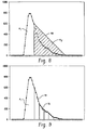
- the processor 26 calculates an estimate of the area of the pulse tail A 2 by assuming the area to be a defined geometric shape, for instance, triangular, as illustrated.
- this embodiment may severely underestimate the total pulse area or energy if pile-up occurs early on as indicated by triangle 90. This error is acceptable for those situations where the pulse rate is sufficiently high to make the storage device 66 ( Figure 1) to retrieve estimator ratios or functions infeasible.
- this method may be refined by reducing the estimated pulse tail to two or more geometric shapes as indicated by Figure 9 areas 94 and 96.
- One advantage of the described embodiments resides in improved energy and spatial resolution.
- pulse tail estimation is not limited to fixed integration times.
- the pulse can be integrated to the maximum integration time when pulse pile-up does not occur.
- Another advantage resides in the elimination of extra extrapolation/amplifier circuits.
- the correction for pulse pile-up can be completed at the sampling rate of the digital sampling circuitry without extra circuits to handle multiple pile-up events.
- Yet another advantage resides in a calibration procedure using a statistically significant number of pulses to determine the estimator function.
- the estimator only assumes that the pulse shape is consistent for the correction to be accurate. In other words, no knowledge of the pulse shape is required.
- Different estimator coefficients can be selected for a given channel's optics or electronics or operating environment, such as temperature.
Landscapes
- Physics & Mathematics (AREA)
- Health & Medical Sciences (AREA)
- Life Sciences & Earth Sciences (AREA)
- General Physics & Mathematics (AREA)
- High Energy & Nuclear Physics (AREA)
- Molecular Biology (AREA)
- Spectroscopy & Molecular Physics (AREA)
- Engineering & Computer Science (AREA)
- Biomedical Technology (AREA)
- General Health & Medical Sciences (AREA)
- Medical Informatics (AREA)
- Nuclear Medicine, Radiotherapy & Molecular Imaging (AREA)
- Optics & Photonics (AREA)
- Nuclear Medicine (AREA)
Abstract
Description
Claims (10)
- A nuclear camera including a plurality of detector heads (10) mounted for movement around a subject in an examination region (12) and a processor (14) for reconstructing signals from the detector heads into an image representation, each detector head comprising: a scintillation crystal (26) for converting each received radiation event into a flash of light; an array of photo-multiplier tubes (28) arranged to receive the light flashes from the scintillation crystal (26), each photo-multiplier tube (28) being arranged to generate an analog tube output pulse in response to each received light flash; a plurality of analog-to-digital convertors (30), at least one of the analog-to-digital converters being connected with each photo-multiplier tube (28) for converting its analog tube output pulse to a series of digital individual tube output values, the processor (14) being arranged to reconstruct the image representation from the individual tube output values; and a storage device (66) for storing an estimator function derived from a calibration radiation event, wherein the processor (14) is arranged to integrate the series of digital values corresponding to a first pulse (50) until the first to occur of the end of the pulse and the detection of a beginning of an overlapping second pulse (52) and, in response to detecting the beginning of the overlapping second pulse, the processor is arranged to access the estimator function in the storage device (66) to estimate a remainder (A2) of the first pulse.
- A nuclear camera as claimed in claim 1, wherein the estimator function includes a plurality of ratios of portions of the calibration event at selected sampling times the processor comprising: a multiplier for multiplying a ratio corresponding a sampling characteristic of the first event at the time which the second event is detected and the integrated digital values between detection of the first and the second events to produce an estimated remainder; and an adder for adding the integrated digital values and the estimated remainder.
- A method of estimating an energy of an event detected by a medical imaging device including: detecting a first event (50); sampling the detected event at a sampling rate; combining the samples from the first detected event; detecting a second event (52) partially coincident with the first event (50); ceasing combining the samples in response to detecting the second event; estimating a remainder (A2) representing an estimate of combined samples of the first event (50) following detection of the second event (52); and for the first event (50), totaling the combined samples of the detected first event (50) and the estimated remainder (A2).
- A method of estimating as claimed in claim 3, further including on detection of the second event: combining sampled values to generate a second event combined value; and removing the estimated remainder (A2) of the first event from the second event combined values.
- A method of estimating as claimed in claim 3 or claim 4, further including: determining a family of estimator functions for the medical imaging device from calibration events.
- A method of estimating as claimed in claim 5, wherein the estimator function determining step includes: calculating ratios of combined samples up to selected sampling times within a portion of a calibration event, to combined samples over the entire calibration event.
- A method of estimating as claimed in claim 5 or claim 6, wherein the estimator function determining step further includes: combining combined calibration samples up to selected times with the corresponding ratios to produce a plurality of remaining area estimates.
- A method of estimating as claimed in any one of claims 3 to 7, wherein the remainder estimating step includes: based on a sampling time substantially coincident with the detection of the second event, retrieving a corresponding ratio; and multiplying the combined samples and the retrieved ratio.
- A method of estimating as claimed in any one of claims 3 to 8, wherein the remainder estimating step includes: based on combined samples of the first event (50) before detection of the second event (52), and the detection time of the second event, retrieving the remaining area estimate (A2).
- A method of estimating as claimed in any one of claims 3 to 9, wherein the remainder estimating step includes: determining an area under at least two points (94, 96) of an estimated pulse tail curve generated from the calibration events.
Applications Claiming Priority (2)
| Application Number | Priority Date | Filing Date | Title |
|---|---|---|---|
| US551092 | 2000-04-18 | ||
| US09/551,092 US6525323B1 (en) | 2000-04-18 | 2000-04-18 | Method and apparatus for improved estimation of characteristics of pulses detected by a nuclear camera |
Publications (2)
| Publication Number | Publication Date |
|---|---|
| EP1148348A2 true EP1148348A2 (en) | 2001-10-24 |
| EP1148348A3 EP1148348A3 (en) | 2006-05-31 |
Family
ID=24199810
Family Applications (1)
| Application Number | Title | Priority Date | Filing Date |
|---|---|---|---|
| EP01303483A Withdrawn EP1148348A3 (en) | 2000-04-18 | 2001-04-12 | Nuclear camera |
Country Status (2)
| Country | Link |
|---|---|
| US (1) | US6525323B1 (en) |
| EP (1) | EP1148348A3 (en) |
Cited By (7)
| Publication number | Priority date | Publication date | Assignee | Title |
|---|---|---|---|---|
| WO2005069040A1 (en) * | 2004-01-13 | 2005-07-28 | Koninklijke Philips Electronics, N.V. | Analog to digital conversion shift error correction |
| WO2009115956A3 (en) * | 2008-03-19 | 2010-06-10 | Koninklijke Philips Electronics N.V. | Single photon radiation detector |
| US9052497B2 (en) | 2011-03-10 | 2015-06-09 | King Abdulaziz City For Science And Technology | Computing imaging data using intensity correlation interferometry |
| US9099214B2 (en) | 2011-04-19 | 2015-08-04 | King Abdulaziz City For Science And Technology | Controlling microparticles through a light field having controllable intensity and periodicity of maxima thereof |
| EP3361288A4 (en) * | 2015-11-05 | 2019-06-26 | Raycan Technology Co., Ltd. (Su Zhou) | METHOD AND SYSTEM FOR REAL TIME PROCESSING OF PULSE STACK EVENT |
| WO2020042664A1 (en) * | 2018-08-27 | 2020-03-05 | 苏州瑞派宁科技有限公司 | Method and device for sampling pulse signal, and computer program medium |
| CN112470039A (en) * | 2018-05-18 | 2021-03-09 | 法国放射性废物管理局 | System and method for imaging by gamma radiation detection |
Families Citing this family (19)
| Publication number | Priority date | Publication date | Assignee | Title |
|---|---|---|---|---|
| US6290728B1 (en) * | 1998-09-10 | 2001-09-18 | Percardia, Inc. | Designs for left ventricular conduit |
| US6603125B1 (en) * | 2000-06-02 | 2003-08-05 | Koninklijke Philips Electronics, N.V. | Event localization and fall-off correction by distance-dependent weighting |
| US6728583B2 (en) * | 2001-06-27 | 2004-04-27 | Koninklijke Philips Electronics N.V. | User interface for a gamma camera which acquires multiple simultaneous data sets |
| DE102005015018B4 (en) * | 2004-04-02 | 2009-01-02 | National Health Research Institutes, Zhunan | Apparatus and method for digitizing gamma-ray energy and characterizing peak-time and decay-time constants without the use of ADCs |
| US7081626B2 (en) * | 2004-06-02 | 2006-07-25 | The Regents Of The University Of California | Apparatus and method for temperature correction and expanded count rate of inorganic scintillation detectors |
| US7894576B2 (en) * | 2006-11-30 | 2011-02-22 | Koninklijke Philips Electronics N.V. | Spectral computed tomography using correlated photon number and energy measurements |
| US7430481B2 (en) * | 2007-01-12 | 2008-09-30 | R. J. Lee Group, Inc. | Methods for detecting and analyzing piled-up X-rays in an X-ray spectrometry system |
| US7741609B2 (en) * | 2007-08-03 | 2010-06-22 | Pulsetor, Llc | Adapting a high-performance pulse processor to an existing spectrometry system |
| EP2183578B1 (en) * | 2007-08-03 | 2018-08-29 | Judith B. Mott Revocable Trust Dated June 6, 2006, As Amended And Restated | Pileup rejection in an energy-dispersive radiation spectrometry system |
| CA2732754C (en) * | 2007-08-03 | 2015-12-08 | Pulsetor, Llc | Digital pulse processor slope correction |
| US7807973B2 (en) * | 2008-08-01 | 2010-10-05 | Pulsetor, Llc | Pileup rejection in an energy-dispersive radiation spectrometry system |
| US8503748B2 (en) * | 2010-08-02 | 2013-08-06 | Toseh Sanaye Tasvirbardari Parto Negar Persia | Nonlinear recursive filter for medical image processing |
| US9606245B1 (en) | 2015-03-24 | 2017-03-28 | The Research Foundation For The State University Of New York | Autonomous gamma, X-ray, and particle detector |
| CN104783829B (en) * | 2015-04-29 | 2017-07-14 | 北京永新医疗设备有限公司 | The processing method and system of single photon emission tomographic imaging |
| AT517499B1 (en) * | 2015-08-12 | 2018-02-15 | Avl List Gmbh | Method and device for detecting signal pulses |
| DE102019122115B4 (en) * | 2019-08-16 | 2024-02-15 | Vega Grieshaber Kg | Detector unit for a scintillation counter, radiometric measuring device with such a detector unit, method for operating such a detector unit and computer program code |
| JP7086119B2 (en) * | 2020-01-17 | 2022-06-17 | キヤノン株式会社 | Signal processing circuit, signal processing method and radiation imaging device |
| JP7347805B2 (en) * | 2020-03-31 | 2023-09-20 | 国立研究開発法人日本原子力研究開発機構 | Nuclear material distribution measuring device |
| CN112731427B (en) * | 2020-12-21 | 2024-07-12 | 奥比中光科技集团股份有限公司 | Distance measurement system and method based on TOF and electronic equipment |
Family Cites Families (5)
| Publication number | Priority date | Publication date | Assignee | Title |
|---|---|---|---|---|
| US5210423A (en) * | 1989-09-22 | 1993-05-11 | Siemens Gammasonics, Inc. | Method and apparatus for unpiling pulses generated by piled-up scintillation events |
| US5270547A (en) * | 1992-05-07 | 1993-12-14 | Independent Scintillation Imaging Systems (Isis) Inc. | Scintillation camera valid event discrimination |
| US5508524A (en) * | 1994-10-03 | 1996-04-16 | Adac Laboratories, Inc. | Spatially variant PMT cluster constitution and spatially variant PMT weights |
| US5585637A (en) * | 1995-06-09 | 1996-12-17 | Adac Laboratories | Multi-head nuclear medicine camera for dual SPECT and PET imaging |
| US6291825B1 (en) * | 1998-10-23 | 2001-09-18 | Adac Laboratories | Method and apparatus for performing pulse pile-up corrections in a gamma camera system |
-
2000
- 2000-04-18 US US09/551,092 patent/US6525323B1/en not_active Expired - Fee Related
-
2001
- 2001-04-12 EP EP01303483A patent/EP1148348A3/en not_active Withdrawn
Cited By (11)
| Publication number | Priority date | Publication date | Assignee | Title |
|---|---|---|---|---|
| WO2005069040A1 (en) * | 2004-01-13 | 2005-07-28 | Koninklijke Philips Electronics, N.V. | Analog to digital conversion shift error correction |
| US7649175B2 (en) | 2004-01-13 | 2010-01-19 | Koninklijke Philips Electronics N.V. | Analog to digital conversion shift error correction |
| WO2009115956A3 (en) * | 2008-03-19 | 2010-06-10 | Koninklijke Philips Electronics N.V. | Single photon radiation detector |
| US8723132B2 (en) | 2008-03-19 | 2014-05-13 | Koninklijke Philips N.V. | Single photon radiation detector |
| CN101978289B (en) * | 2008-03-19 | 2014-07-30 | 皇家飞利浦电子股份有限公司 | Single photon radiation detector |
| US9052497B2 (en) | 2011-03-10 | 2015-06-09 | King Abdulaziz City For Science And Technology | Computing imaging data using intensity correlation interferometry |
| US9099214B2 (en) | 2011-04-19 | 2015-08-04 | King Abdulaziz City For Science And Technology | Controlling microparticles through a light field having controllable intensity and periodicity of maxima thereof |
| EP3361288A4 (en) * | 2015-11-05 | 2019-06-26 | Raycan Technology Co., Ltd. (Su Zhou) | METHOD AND SYSTEM FOR REAL TIME PROCESSING OF PULSE STACK EVENT |
| CN112470039A (en) * | 2018-05-18 | 2021-03-09 | 法国放射性废物管理局 | System and method for imaging by gamma radiation detection |
| WO2020042664A1 (en) * | 2018-08-27 | 2020-03-05 | 苏州瑞派宁科技有限公司 | Method and device for sampling pulse signal, and computer program medium |
| US11944470B2 (en) | 2018-08-27 | 2024-04-02 | Raycan Technology Co., Ltd. (Suzhou) | Method and device for sampling a pulse signal, and computer program medium |
Also Published As
| Publication number | Publication date |
|---|---|
| EP1148348A3 (en) | 2006-05-31 |
| US6525323B1 (en) | 2003-02-25 |
Similar Documents
| Publication | Publication Date | Title |
|---|---|---|
| US6525323B1 (en) | Method and apparatus for improved estimation of characteristics of pulses detected by a nuclear camera | |
| Kemp et al. | NEMA NU 2-2007 performance measurements of the Siemens Inveon™ preclinical small animal PET system | |
| JP3343122B2 (en) | An automated coincidence timing calibration method for PET scanners | |
| US5376795A (en) | Emission-transmission imaging system using single energy and dual energy transmission and radionuclide emission data | |
| US9029786B2 (en) | Nuclear medicine imaging apparatus, and nuclear medicine imaging method | |
| US5489782A (en) | Method and apparatus for quantum-limited data acquisition | |
| US6603125B1 (en) | Event localization and fall-off correction by distance-dependent weighting | |
| US8340377B2 (en) | Method for energy calculation and pileup determination for continuously sampled nuclear pulse processing | |
| EP1828977B1 (en) | Restoration of the nuclear medicine 2d planar image by iterative constrained deconvolution | |
| US5532489A (en) | Positron imaging apparatus | |
| US9784854B2 (en) | Direct conversion radiation detector digital signal processing electronics | |
| US9427193B2 (en) | Digital integration with detector correction | |
| CN110327067A (en) | Image rebuilding method, device, terminal device and PET system | |
| US8022368B2 (en) | Hybrid method for randoms variance reduction | |
| Watanabe et al. | A high-throughput whole-body PET scanner using flat panel PS-PMTs | |
| US8563935B2 (en) | Nuclear medicine imaging apparatus and control method | |
| JP3643432B2 (en) | Nuclear medicine diagnostic equipment | |
| Karuta et al. | Effect of detector weighting functions on the point spread function of high-resolution PET tomographs: a simulation study | |
| EP0589467B1 (en) | Nuclear medicine imaging apparatus | |
| Yamada et al. | Development of a small animal PET scanner using DOI detectors | |
| US5424946A (en) | Adaptive angular transmission filter for pet scanner | |
| JP2626461B2 (en) | Nuclear medicine imaging equipment | |
| US7589325B2 (en) | Method for recording a digital x-ray image, counting x-ray detector and x-ray system | |
| JP2016188833A (en) | Nuclear medicine imaging device and nuclear medicine imaging method | |
| Tai et al. | Optimal coincidence time window for ECAT exact HR plus |
Legal Events
| Date | Code | Title | Description |
|---|---|---|---|
| PUAI | Public reference made under article 153(3) epc to a published international application that has entered the european phase |
Free format text: ORIGINAL CODE: 0009012 |
|
| AK | Designated contracting states |
Kind code of ref document: A2 Designated state(s): AT BE CH CY DE DK ES FI FR GB GR IE IT LI LU MC NL PT SE TR |
|
| AX | Request for extension of the european patent |
Free format text: AL;LT;LV;MK;RO;SI |
|
| RAP1 | Party data changed (applicant data changed or rights of an application transferred) |
Owner name: PHILIPS MEDICAL SYSTEMS (CLEVELAND), INC. |
|
| RAP1 | Party data changed (applicant data changed or rights of an application transferred) |
Owner name: KONINKLIJKE PHILIPS ELECTRONICS N.V. |
|
| PUAL | Search report despatched |
Free format text: ORIGINAL CODE: 0009013 |
|
| AK | Designated contracting states |
Kind code of ref document: A3 Designated state(s): AT BE CH CY DE DK ES FI FR GB GR IE IT LI LU MC NL PT SE TR |
|
| AX | Request for extension of the european patent |
Extension state: AL LT LV MK RO SI |
|
| RIC1 | Information provided on ipc code assigned before grant |
Ipc: G01T 1/17 20060101ALI20060413BHEP Ipc: G01T 1/29 20060101ALI20060413BHEP Ipc: G01T 1/164 20060101AFI20010801BHEP |
|
| 17P | Request for examination filed |
Effective date: 20061130 |
|
| AKX | Designation fees paid |
Designated state(s): AT BE CH CY DE DK ES FI FR GB GR IE IT LI LU MC NL PT SE TR |
|
| 17Q | First examination report despatched |
Effective date: 20070129 |
|
| STAA | Information on the status of an ep patent application or granted ep patent |
Free format text: STATUS: THE APPLICATION IS DEEMED TO BE WITHDRAWN |
|
| 18D | Application deemed to be withdrawn |
Effective date: 20080617 |