EP1148273A1 - Torque estimation method for internal combustion engine and its accessories - Google Patents
Torque estimation method for internal combustion engine and its accessories Download PDFInfo
- Publication number
- EP1148273A1 EP1148273A1 EP01302463A EP01302463A EP1148273A1 EP 1148273 A1 EP1148273 A1 EP 1148273A1 EP 01302463 A EP01302463 A EP 01302463A EP 01302463 A EP01302463 A EP 01302463A EP 1148273 A1 EP1148273 A1 EP 1148273A1
- Authority
- EP
- European Patent Office
- Prior art keywords
- engine
- torque
- accessory
- operating condition
- method recited
- Prior art date
- Legal status (The legal status is an assumption and is not a legal conclusion. Google has not performed a legal analysis and makes no representation as to the accuracy of the status listed.)
- Granted
Links
Images



Classifications
-
- B—PERFORMING OPERATIONS; TRANSPORTING
- B60—VEHICLES IN GENERAL
- B60H—ARRANGEMENTS OF HEATING, COOLING, VENTILATING OR OTHER AIR-TREATING DEVICES SPECIALLY ADAPTED FOR PASSENGER OR GOODS SPACES OF VEHICLES
- B60H1/00—Heating, cooling or ventilating devices
- B60H1/32—Cooling devices
- B60H1/3204—Cooling devices using compression
- B60H1/3205—Control means therefor
- B60H1/3216—Control means therefor for improving a change in operation duty of a compressor in a vehicle
-
- F—MECHANICAL ENGINEERING; LIGHTING; HEATING; WEAPONS; BLASTING
- F02—COMBUSTION ENGINES; HOT-GAS OR COMBUSTION-PRODUCT ENGINE PLANTS
- F02D—CONTROLLING COMBUSTION ENGINES
- F02D41/00—Electrical control of supply of combustible mixture or its constituents
- F02D41/02—Circuit arrangements for generating control signals
- F02D41/021—Introducing corrections for particular conditions exterior to the engine
- F02D41/0215—Introducing corrections for particular conditions exterior to the engine in relation with elements of the transmission
- F02D41/0225—Introducing corrections for particular conditions exterior to the engine in relation with elements of the transmission in relation with the gear ratio or shift lever position
-
- F—MECHANICAL ENGINEERING; LIGHTING; HEATING; WEAPONS; BLASTING
- F02—COMBUSTION ENGINES; HOT-GAS OR COMBUSTION-PRODUCT ENGINE PLANTS
- F02D—CONTROLLING COMBUSTION ENGINES
- F02D41/00—Electrical control of supply of combustible mixture or its constituents
- F02D41/02—Circuit arrangements for generating control signals
- F02D41/04—Introducing corrections for particular operating conditions
- F02D41/08—Introducing corrections for particular operating conditions for idling
- F02D41/083—Introducing corrections for particular operating conditions for idling taking into account engine load variation, e.g. air-conditionning
-
- B—PERFORMING OPERATIONS; TRANSPORTING
- B60—VEHICLES IN GENERAL
- B60H—ARRANGEMENTS OF HEATING, COOLING, VENTILATING OR OTHER AIR-TREATING DEVICES SPECIALLY ADAPTED FOR PASSENGER OR GOODS SPACES OF VEHICLES
- B60H1/00—Heating, cooling or ventilating devices
- B60H1/32—Cooling devices
- B60H2001/3269—Cooling devices output of a control signal
- B60H2001/327—Cooling devices output of a control signal related to a compressing unit
- B60H2001/3273—Cooling devices output of a control signal related to a compressing unit related to the operation of the vehicle, e.g. the compressor driving torque
-
- F—MECHANICAL ENGINEERING; LIGHTING; HEATING; WEAPONS; BLASTING
- F02—COMBUSTION ENGINES; HOT-GAS OR COMBUSTION-PRODUCT ENGINE PLANTS
- F02D—CONTROLLING COMBUSTION ENGINES
- F02D2200/00—Input parameters for engine control
- F02D2200/02—Input parameters for engine control the parameters being related to the engine
- F02D2200/10—Parameters related to the engine output, e.g. engine torque or engine speed
- F02D2200/1002—Output torque
- F02D2200/1004—Estimation of the output torque
-
- F—MECHANICAL ENGINEERING; LIGHTING; HEATING; WEAPONS; BLASTING
- F02—COMBUSTION ENGINES; HOT-GAS OR COMBUSTION-PRODUCT ENGINE PLANTS
- F02D—CONTROLLING COMBUSTION ENGINES
- F02D2200/00—Input parameters for engine control
- F02D2200/02—Input parameters for engine control the parameters being related to the engine
- F02D2200/10—Parameters related to the engine output, e.g. engine torque or engine speed
- F02D2200/1006—Engine torque losses, e.g. friction or pumping losses or losses caused by external loads of accessories
-
- F—MECHANICAL ENGINEERING; LIGHTING; HEATING; WEAPONS; BLASTING
- F02—COMBUSTION ENGINES; HOT-GAS OR COMBUSTION-PRODUCT ENGINE PLANTS
- F02D—CONTROLLING COMBUSTION ENGINES
- F02D2400/00—Control systems adapted for specific engine types; Special features of engine control systems not otherwise provided for; Power supply, connectors or cabling for engine control systems
- F02D2400/12—Engine control specially adapted for a transmission comprising a torque converter or for continuously variable transmissions
-
- F—MECHANICAL ENGINEERING; LIGHTING; HEATING; WEAPONS; BLASTING
- F16—ENGINEERING ELEMENTS AND UNITS; GENERAL MEASURES FOR PRODUCING AND MAINTAINING EFFECTIVE FUNCTIONING OF MACHINES OR INSTALLATIONS; THERMAL INSULATION IN GENERAL
- F16H—GEARING
- F16H59/00—Control inputs to control units of change-speed- or reversing-gearings for conveying rotary motion
- F16H59/14—Inputs being a function of torque or torque demand
- F16H2059/145—Inputs being a function of torque or torque demand being a function of power demand of auxiliary devices
-
- F—MECHANICAL ENGINEERING; LIGHTING; HEATING; WEAPONS; BLASTING
- F16—ENGINEERING ELEMENTS AND UNITS; GENERAL MEASURES FOR PRODUCING AND MAINTAINING EFFECTIVE FUNCTIONING OF MACHINES OR INSTALLATIONS; THERMAL INSULATION IN GENERAL
- F16H—GEARING
- F16H59/00—Control inputs to control units of change-speed- or reversing-gearings for conveying rotary motion
- F16H59/14—Inputs being a function of torque or torque demand
Definitions
- the field of the invention relates to a control of a vehicle equipped with an automatic or manual transmission, and in particular to an engine torque control based on estimates of accessory loading.
- Vehicles have an engine and various accessories such as an air conditioning (A/C) compressor, power steering pump, or alternator intermittently coupled to the engine.
- A/C air conditioning
- the A/C compressor is coupled to the engine via the A/C compressor clutch.
- A/C compressor When the A/C compressor is engaged, it consumes a certain amount of engine combustion torque. When this happens, a vehicle driver can feel the impact of A/C compressor engaging, and thus drive feel is degraded.
- Better engine control and improved drive feel are achieved by estimating A/C compressor load torque and adjusting engine torque accordingly. In other words, by increasing engine torque in response to increased accessory load torque, degradation in vehicle performance is avoided, and driver comfort during A/C compressor engagement is improved.
- the inventors herein have recognised a disadvantage with this approach.
- variations in the torque converter fluid characteristics can cause reduced accuracy.
- estimating torque using torque converter characteristics is susceptible to variations in hydraulic fluid properties. For example, when the fluid is cold, it is more viscous, and torque prediction will not be as accurate.
- accessory torque estimates are affected by the variation in hydraulic fluid properties.
- An object of the present invention is to provide a method for calculating load torque of an accessory device coupled to an engine.
- an accessory load torque estimation method for use with an internal combustion engine having a torque converter and an accessory, the engine and the accessory coupled to a vehicle.
- the method comprises learning engine torque based on an engine operating condition when torque converter torque is less than a predetermined value and the accessory is disengaged; and estimating a load torque of the accessory based on said operating condition and said residual engine torque when said torque converter torque is less than said predetermined value and the accessory is engaged.
- An advantage of the above aspect of the invention is that a more precise method of engine torque control is achieved. Another advantage is that improved drive feel is achieved during accessory engagements.
- Transmission 15 is an electronically controlled transmission with a plurality of selectable discrete gear ratios. Transmission 15 also includes various other gears such as, for example, a final drive ratio (not shown). Transmission 15 is also coupled to tire 19 via axle 21. Tire 19 interfaces the vehicle (not shown) to the road 23.
- transmission 15 can be a manually operated transmission and torque converter 11 can be eliminated.
- Engine 10 having a plurality of cylinders, one cylinder of which is shown in Figure 2, is controlled by electronic engine controller 12.
- Engine 10 includes combustion chamber 30 and cylinder walls 32 with piston 36 positioned therein and connected to crankshaft 13.
- Combustion chamber 30 communicates with intake manifold 44 and exhaust manifold 48 via respective intake valve 52 and exhaust valve 54.
- Exhaust gas oxygen sensor 16 is coupled to exhaust manifold 48 of engine 10 upstream of catalytic converter 20.
- sensor 16 is a HEGO sensor as is known to those skilled in the art.
- Intake manifold 44 communicates with throttle body 64 via throttle plate 66. Throttle plate 66 is controlled by electric motor 67, which receives a signal from ETC driver 69. ETC driver 69 receives control signal (DC) from controller 12. Intake manifold 44 is also shown having fuel injector 68 coupled thereto for delivering fuel in proportion to the pulse width of signal (fpw) from controller 12. Fuel is delivered to fuel injector 68 by a conventional fuel system (not shown) including a fuel tank, fuel pump, and fuel rail (not shown).
- Engine 10 further includes conventional distributorless ignition system 88 to provide ignition spark to combustion chamber 30 via spark plug 92 in response to controller 12.
- controller 12 is a conventional microcomputer including: microprocessor unit 102, input/output ports 104, electronic memory chip 106, which is an electronically programmable memory in this particular example, random access memory 108, and a conventional data bus.
- Controller 12 receives various signals from sensors coupled to engine 10, in addition to those signals previously discussed, including: measurements of inducted mass air flow (MAF) from mass air flow sensor 110 coupled to throttle body 64; engine coolant temperature (ECT) from temperature sensor 112 coupled to cooling jacket 114; a measurement of throttle position (TP) from throttle position sensor 117 coupled to throttle plate 66; a measurement of transmission shaft torque, or engine shaft torque from torque sensor 121, a measurement of turbine speed (Wt) from turbine speed sensor 119, where turbine speed measures the speed of shaft 17, and a profile ignition pickup signal (PIP) from Hall effect sensor 118 coupled to crankshaft 13 indicating an engine speed (We).
- turbine speed may be determined from vehicle speed and gear ratio.
- accelerator pedal 130 is shown communicating with the driver's foot 132. Accelerator pedal position (PP) is measured by pedal position sensor 134 and sent to controller 12.
- PP Accelerator pedal position
- an air bypass valve (not shown) can be installed to allow a controlled amount of air to bypass throttle plate 62.
- the air bypass valve (not shown) receives a control signal (not shown) from controller 12.
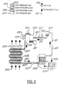
- FIG. 3 an air conditioning (A/C) system is shown.
- Arrows 201 indicate direction of refrigerant, or working fluid, flow.
- Arrows 200 indicate direction of air flow that is circulated through the engine compartment (not shown).
- Arrows 206 indicate direction of air flow that is circulated through the cabin (not shown).
- Solid shading 202 indicates working fluid is a high pressure gas
- left handed cross-hatching 203 indicates working fluid is a high pressure liquid
- right handed cross-hatching 204 indicates working fluid is a low pressure liquid
- no shading 205 indicates working fluid is a low pressure gas.
- Working fluid is circulated through the A/C system via line 207.
- Compressor 220 which is shown coupled to engine 10 via clutch 219, is located between high pressure gas 202 and low pressure gas 205. Upstream of compressor 220, is low pressure service port 222 and A/C cycling switch 223. Suction Accumulator/drier 224 is upstream of cycling switch 223. Further up is A/C evaporator core 226, which is coupled to blower motor 225. Next are A/C evaporator orifice 227 and A/C condenser core 228, which is coupled to radiator fan 233. High pressure service port 229, compressor relief valve 230, and A/C pressure cut-off switch 231 are upstream of A/C condenser core 228.
- a description of an A/C thermodynamic process is now presented.
- low pressure gas 205 is compressed to high pressure gas 202, rising in temperature due to compression.
- Compressor relief valve 230 prevents high pressure gas 202 from reaching a maximum allowable high pressure gas pressure.
- A/C pressure cut-off switch 231 disengages compressor 200 from engine 10 via clutch 219.
- High pressure gas 202 sheds heat to the atmosphere at A/C condenser core 228, changing phase to high pressure liquid 203 as it cools.
- high pressure liquid 203 expands to low pressure liquid 204.
- low pressure liquid 203 passes through a jet (not shown) and evaporates into low pressure gas 205. This action cools the working fluid, A/C evaporator core 226, and cabin airflow 206.
- Low pressure liquid 204 continues to suction accumulator/drier 224 and A/C cycling switch 223.
- A/C cycling switch 223 signals to engage compressor 220 to engine 10 via clutch 219 when measured pressure is above a predetermined maximum pressure.
- A/C cycling switch 223 also signals to disengage compressor 220 from engine 10 via clutch 219 when measured pressure is below a predetermined minimum pressure.
- These setpoint pressures are typically 45 psi and 24.5 psi, respectively. They are designed to keep A/C evaporator core 226 just above freezing.
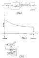
- FIG 4 a typical graph of A/C torque level vs. Time is shown. This is the assumed shape used in part to estimate A/C load as described later herein. In other words, the routines described herein in part learn an offset value that is used to adjust the curve of Figure 4.
- step 500 accessory(other than A/C) engagement status flag is read and stored.
- step 510 a determination is made whether the torque converter clutch is unlocked. If the answer in step 510 is NO, the routine proceeds to step 620 whereupon a decision is made whether the transmission is in the gear with engine breaking. Typically, transmissions are built with engine breaking prevented in lower gears. The flowchart in Figure 5 provides for engine breaking prevention in any transmission gear. If the answer to step 620 is NO, the routine is exited.
- step 620 the routine proceeds to step 630 whereupon a determination is made whether the accessory (other than A/C) status remains unchanged. If the answer to step 630 is NO, the routine is exited. If the answer to step 630 is YES, the routine proceeds to step 640 whereupon a determination is made whether the A/C is ON. If the answer to step 640 is YES, the routine proceeds to step 650, and a determination is made whether wheel speed has just become greater than engine speed by a small preselected tolerance amount. Alternatively, a determination can be made whether engine speed has just become greater than the wheel speed times the gear ratio of the transmission, or, if it was greater, has just become less.
- step 650 the routine is exited. If the answer to step 650 is YES, the routine proceeds to step 550 as described further down. If the answer to step 640 is NO, the routine proceeds to step 660 whereupon a determination is made whether wheel speed is greater than engine speed by a small preselected tolerance amount. If the answer to step 660 is NO, the routine exits. If the answer to step 660 is YES, the routine proceeds to step 600 as described bellow. If the answer to step 510 is YES, a determination is made in step 520 whether accessory (other than A/C) engagement status remains unchanged.
- step 520 If the answer in step 520 is NO, the routine is exited. If the answer to step 520 is YES, a determination is made in step 530 whether the A/C is ON. If the answer in step 530 is NO, a determination is made in step 580 whether the speed ratio (turbine speed/engine speed) is substantially equal to one. Alternatively, an embodiment could be used where the speed ratio is set within a small predetermined range. When the speed ratio is substantially equal to one, it is known that the input torque to the torque converter, T n , is substantially equal to zero. If the answer to step 580 is NO, the routine is exited.
- the speed ratio turbine speed/engine speed
- This residual torque is the difference between the uncorrected open loop torque model and the estimate of torque across the torque converter, T n .
- the torque converter torque is substantially zero when the engine is in neutral, or when the torque converter is open, and the speed ratio across it is substantially one, or at the point when a transmission overrunning clutch becomes engaged to prevent engine breaking or disengaged to provide engine breaking.
- Engine breaking is prevented by an overrunning clutch that produces a one-way drive connection between a gear unit and a nonrotating powertrain member, such as transmission casing.
- the overrunning clutch is engaged when the wheel speed becomes greater than the engine speed by a small preselected tolerance amount. When the overrunning clutch becomes engaged, engine breaking is prevented.
- step 540 determines whether the speed ratio is substantially equal to 1. If the answer to step 540 is NO, the routine is exited. If the answer to step 540 is YES, the routine proceeds to step 550 whereupon a determination is made whether the A/C ON command is issued for the first time. When the A/C clutch is engaged, there is a spike in the torque that eventually levels off. Also, the magnitude of the A/C torque curve is higher when the A/C ON command is issued for the first time.
- step 700 a determination is made whether the A/C is on. If the answer to step 700 is NO, the value of the A/C load torque, T a/c , is set to zero. If the answer to step 700 is YES, a determination is made in step 710 whether this is the first engagement.
- f 4 ( t ) is of the form shown in Figure 4.
- Functions f 1 ( n ), f 2 ( t ), and f 3 ( a / c _ load ) are also calibratable functions, where a/c_load is determined from pressure sensor coupled either upstream or downstream of the A/C compressor.
- Operating conditions are engine airflow, engine speed, ignition timing, manifold pressure, throttle valve position, loading from accessories other than A/C, and/or any combination of the above. Further, any parameter known to those skilled in the art to indicate engine torque can be used with or in place of the above parameters.
- an improved estimate of engine output torque is achieved that is adapted to account for changes in engine friction and/or changes in accessory loading that are not accounted for in the open loop engine and accessory loading models.
- the determinations of whether speed ratio across the torque converter is substantially unity can be replaced with determinations as to whether the transmission is in neutral and engine speed is substantially constant.
- engine speed is substantially constant when engine acceleration is less than a predetermined level.
- Figure 7 is a routine for calculating the amount of time elapsed since the A/C compressor has been turned on.
- timer is initialised to zero.
- step 410 a determination is made whether the A/C is turned on. If the answer to step 410 is YES, timer is incremented by 1 in step 420. If the answer in step 410 is NO, timer value is exited.
- step 800 desired engine torque is determined based on operator input, such as pedal position.
- step 810 torque error is calculated between the desired torque and engine output torque T e as calculated in Figure 6 step 730, followed by step 820, where engine parameters, such as mass airflow, air/fuel ratio, spark timing, throttle position, etc., are adjusted to control actual engine torque to desired engine torque.
- engine parameters such as mass airflow, air/fuel ratio, spark timing, throttle position, etc.
- a more accurate A/C torque level is calculated by taking into account variations in the open loop A/C torque with respect to time. This value can be provided to the engine controller to more accurately control engine torque when the A/C is engaged, disengaged, or transitioning between the two.
- accessory load torque In addition to the A/C torque as a function of time model, various other parameters can be factored in when estimating accessory load torque, such as engine speed, intake air temperature, cabin temperature, humidity, or any other parameter known to those skilled in the art to affect accessory load torque.
Landscapes
- Engineering & Computer Science (AREA)
- Mechanical Engineering (AREA)
- Chemical & Material Sciences (AREA)
- Combustion & Propulsion (AREA)
- General Engineering & Computer Science (AREA)
- Physics & Mathematics (AREA)
- Thermal Sciences (AREA)
- Control Of Vehicle Engines Or Engines For Specific Uses (AREA)
- Combined Controls Of Internal Combustion Engines (AREA)
Abstract
Description
- The field of the invention relates to a control of a vehicle equipped with an automatic or manual transmission, and in particular to an engine torque control based on estimates of accessory loading.
- Vehicles have an engine and various accessories such as an air conditioning (A/C) compressor, power steering pump, or alternator intermittently coupled to the engine. The A/C compressor is coupled to the engine via the A/C compressor clutch. When the A/C compressor is engaged, it consumes a certain amount of engine combustion torque. When this happens, a vehicle driver can feel the impact of A/C compressor engaging, and thus drive feel is degraded. Better engine control and improved drive feel are achieved by estimating A/C compressor load torque and adjusting engine torque accordingly. In other words, by increasing engine torque in response to increased accessory load torque, degradation in vehicle performance is avoided, and driver comfort during A/C compressor engagement is improved.
- One control method of this kind is described in U.S. Patent 5,826,208. Engine output torque is calculated by using engine characteristics, and torque converter torque is calculated using torque converter characteristic. In the low-speed, light-load vehicle operation region the impact of the load torque of accessory devices is relatively large compared with the output torque of the engine. Therefore, when the speed ratio is relatively small, accessory load torque can be calculated as the difference between the output torque of the engine and the torque converter torque.
- The inventors herein have recognised a disadvantage with this approach. In particular, when the torque converter torque is interpolated from the characteristic map of the torque converter ratio as related to the speed ratio, variations in the torque converter fluid characteristics can cause reduced accuracy. In other words, estimating torque using torque converter characteristics is susceptible to variations in hydraulic fluid properties. For example, when the fluid is cold, it is more viscous, and torque prediction will not be as accurate. Thus, accessory torque estimates are affected by the variation in hydraulic fluid properties.
- Another disadvantage is that this method does not account for the torque due to losses from friction work, pumping work, accessory load other than A/C, etc. The above approach does not distinguish between the above "loss" torques and A/C load torque. Variations in this "loss" torque can cause further inaccuracies in estimated accessory load torque. Additionally, the above method cannot be used when the torque converter is locked, which is a large proportion of the vehicle drive cycle.
- An object of the present invention is to provide a method for calculating load torque of an accessory device coupled to an engine.
- The above object is achieved and disadvantages of prior approaches overcome by an accessory load torque estimation method for use with an internal combustion engine having a torque converter and an accessory, the engine and the accessory coupled to a vehicle. The method comprises learning engine torque based on an engine operating condition when torque converter torque is less than a predetermined value and the accessory is disengaged; and estimating a load torque of the accessory based on said operating condition and said residual engine torque when said torque converter torque is less than said predetermined value and the accessory is engaged.
- An advantage of the above aspect of the invention is that a more precise method of engine torque control is achieved. Another advantage is that improved drive feel is achieved during accessory engagements.
- Other objects, features and advantages of the present invention will be readily appreciated by the reader of this specification.
- The object and advantages of the invention claimed herein will be more readily understood by reading an example of an embodiment in which the invention is used to advantage with reference to the following drawings wherein:
- Figure 1 is a block diagram of a vehicle illustrating various components related to the present invention;
- Figure 2 is a block diagram of an engine in which the invention is used to advantage;
- Figure 3 is a block diagram of an air conditioning system illustrating various components related to this invention;
- Figure 4 is a graph of A/C torque level vs. Time; and Figures 5, 6, 7 and 8 are block diagrams of embodiments in which the invention is used to advantage.
-
- Referring to Figure 1,
internal combustion engine 10, further described herein with particular reference to Figure 2, is shown coupled to torque converter 11 viacrankshaft 13. Torque converter 11 is also coupled totransmission 15 viaturbine shaft 17 which is also known as a transmission input shaft. Torque converter 11 has a bypass clutch (not shown) which can be engaged, disengaged, or partially engaged. When bypass clutch is either disengaged or partially engaged, torque converter 11 is said to be in an unlocked state.Transmission 15 is an electronically controlled transmission with a plurality of selectable discrete gear ratios.Transmission 15 also includes various other gears such as, for example, a final drive ratio (not shown).Transmission 15 is also coupled totire 19 via axle 21. Tire 19 interfaces the vehicle (not shown) to theroad 23. In an alternative embodiment,transmission 15 can be a manually operated transmission and torque converter 11 can be eliminated. -
Internal combustion engine 10 having a plurality of cylinders, one cylinder of which is shown in Figure 2, is controlled by electronic engine controller 12.Engine 10 includescombustion chamber 30 and cylinder walls 32 with piston 36 positioned therein and connected tocrankshaft 13.Combustion chamber 30 communicates withintake manifold 44 andexhaust manifold 48 viarespective intake valve 52 andexhaust valve 54. Exhaust gas oxygen sensor 16 is coupled toexhaust manifold 48 ofengine 10 upstream ofcatalytic converter 20. In a preferred embodiment, sensor 16 is a HEGO sensor as is known to those skilled in the art. -
Intake manifold 44 communicates withthrottle body 64 viathrottle plate 66.Throttle plate 66 is controlled byelectric motor 67, which receives a signal from ETC driver 69. ETC driver 69 receives control signal (DC) from controller 12.Intake manifold 44 is also shown havingfuel injector 68 coupled thereto for delivering fuel in proportion to the pulse width of signal (fpw) from controller 12. Fuel is delivered tofuel injector 68 by a conventional fuel system (not shown) including a fuel tank, fuel pump, and fuel rail (not shown). -
Engine 10 further includes conventionaldistributorless ignition system 88 to provide ignition spark tocombustion chamber 30 viaspark plug 92 in response to controller 12. In the embodiment described herein, controller 12 is a conventional microcomputer including:microprocessor unit 102, input/output ports 104,electronic memory chip 106, which is an electronically programmable memory in this particular example,random access memory 108, and a conventional data bus. - Controller 12 receives various signals from sensors coupled to
engine 10, in addition to those signals previously discussed, including: measurements of inducted mass air flow (MAF) from mass air flow sensor 110 coupled tothrottle body 64; engine coolant temperature (ECT) fromtemperature sensor 112 coupled tocooling jacket 114; a measurement of throttle position (TP) from throttle position sensor 117 coupled tothrottle plate 66; a measurement of transmission shaft torque, or engine shaft torque from torque sensor 121, a measurement of turbine speed (Wt) fromturbine speed sensor 119, where turbine speed measures the speed ofshaft 17, and a profile ignition pickup signal (PIP) fromHall effect sensor 118 coupled tocrankshaft 13 indicating an engine speed (We). Alternatively, turbine speed may be determined from vehicle speed and gear ratio. - Continuing with Figure 2,
accelerator pedal 130 is shown communicating with the driver'sfoot 132. Accelerator pedal position (PP) is measured by pedal position sensor 134 and sent to controller 12. - In an alternative embodiment, where an electronically controlled throttle is not used, an air bypass valve (not shown) can be installed to allow a controlled amount of air to bypass throttle plate 62. In this alternative embodiment, the air bypass valve (not shown) receives a control signal (not shown) from controller 12.
- Referring now to Figure 3, an air conditioning (A/C) system is shown.
Arrows 201 indicate direction of refrigerant, or working fluid, flow. Arrows 200 indicate direction of air flow that is circulated through the engine compartment (not shown).Arrows 206 indicate direction of air flow that is circulated through the cabin (not shown).Solid shading 202 indicates working fluid is a high pressure gas, left handed cross-hatching 203 indicates working fluid is a high pressure liquid, right handed cross-hatching 204 indicates working fluid is a low pressure liquid, and no shading 205 indicates working fluid is a low pressure gas. Working fluid is circulated through the A/C system vialine 207. -
Compressor 220, which is shown coupled toengine 10 viaclutch 219, is located betweenhigh pressure gas 202 andlow pressure gas 205. Upstream ofcompressor 220, is lowpressure service port 222 and A/C cycling switch 223. Suction Accumulator/drier 224 is upstream ofcycling switch 223. Further up is A/C evaporator core 226, which is coupled toblower motor 225. Next are A/C evaporator orifice 227 and A/C condenser core 228, which is coupled toradiator fan 233. Highpressure service port 229,compressor relief valve 230, and A/C pressure cut-off switch 231 are upstream of A/C condenser core 228. - A description of an A/C thermodynamic process is now presented. Starting at
compressor 220,low pressure gas 205 is compressed tohigh pressure gas 202, rising in temperature due to compression.Compressor relief valve 230 preventshigh pressure gas 202 from reaching a maximum allowable high pressure gas pressure. A/C pressure cut-off switch 231 disengages compressor 200 fromengine 10 viaclutch 219. -
High pressure gas 202 sheds heat to the atmosphere at A/C condenser core 228, changing phase to high pressure liquid 203 as it cools. At A/C evaporator orifice 227, high pressure liquid 203 expands to low pressure liquid 204. At A/C evaporator core 226 low pressure liquid 203 passes through a jet (not shown) and evaporates intolow pressure gas 205. This action cools the working fluid, A/C evaporator core 226, andcabin airflow 206. - Low pressure liquid 204 continues to suction accumulator/drier 224 and A/
C cycling switch 223. A/C cycling switch 223 signals to engagecompressor 220 toengine 10 viaclutch 219 when measured pressure is above a predetermined maximum pressure. A/C cycling switch 223 also signals to disengagecompressor 220 fromengine 10 viaclutch 219 when measured pressure is below a predetermined minimum pressure. These setpoint pressures are typically 45 psi and 24.5 psi, respectively. They are designed to keep A/C evaporator core 226 just above freezing. Whencompressor 220 cycles between engaged and disengaged due solely to A/C cycling switch 223, it is referred to herein as normal, or uninterrupted, cycling. - Referring now to Figure 4, a typical graph of A/C torque level vs. Time is shown. This is the assumed shape used in part to estimate A/C load as described later herein. In other words, the routines described herein in part learn an offset value that is used to adjust the curve of Figure 4.
- Referring now to Figure 5, a routine is described for determining residual engine torque and A/C load torque instantaneous error according to the present invention. First, in step 500 accessory(other than A/C) engagement status flag is read and stored. Next, in
step 510, a determination is made whether the torque converter clutch is unlocked. If the answer instep 510 is NO, the routine proceeds to step 620 whereupon a decision is made whether the transmission is in the gear with engine breaking. Typically, transmissions are built with engine breaking prevented in lower gears. The flowchart in Figure 5 provides for engine breaking prevention in any transmission gear. If the answer to step 620 is NO, the routine is exited. If the answer to step 620 is YES, the routine proceeds to step 630 whereupon a determination is made whether the accessory (other than A/C) status remains unchanged. If the answer to step 630 is NO, the routine is exited. If the answer to step 630 is YES, the routine proceeds to step 640 whereupon a determination is made whether the A/C is ON. If the answer to step 640 is YES, the routine proceeds to step 650, and a determination is made whether wheel speed has just become greater than engine speed by a small preselected tolerance amount. Alternatively, a determination can be made whether engine speed has just become greater than the wheel speed times the gear ratio of the transmission, or, if it was greater, has just become less. In other words, if the clutch was overrunning and then stopped over-running, a transition through zero torque has again occurred. If the answer to step 650 is NO, the routine is exited. If the answer to step 650 is YES, the routine proceeds to step 550 as described further down. If the answer to step 640 is NO, the routine proceeds to step 660 whereupon a determination is made whether wheel speed is greater than engine speed by a small preselected tolerance amount. If the answer to step 660 is NO, the routine exits. If the answer to step 660 is YES, the routine proceeds to step 600 as described bellow. If the answer to step 510 is YES, a determination is made instep 520 whether accessory (other than A/C) engagement status remains unchanged. If the answer instep 520 is NO, the routine is exited. If the answer to step 520 is YES, a determination is made instep 530 whether the A/C is ON. If the answer instep 530 is NO, a determination is made in step 580 whether the speed ratio (turbine speed/engine speed) is substantially equal to one. Alternatively, an embodiment could be used where the speed ratio is set within a small predetermined range. When the speed ratio is substantially equal to one, it is known that the input torque to the torque converter, T n , is substantially equal to zero. If the answer to step 580 is NO, the routine is exited. If the answer to step 580 is YES, the routine proceeds to step 590 wherein the instantaneous value of residual engine torque, T resid , is calculated from the estimated value of the engine output torque, T e , calculated instep 730 Figure 6, the current adaptive term, T f , and the expected torque converter torque at speed ratio of one, T n : - This residual torque is the difference between the uncorrected open loop torque model and the estimate of torque across the torque converter, T n . The torque converter torque is substantially zero when the engine is in neutral, or when the torque converter is open, and the speed ratio across it is substantially one, or at the point when a transmission overrunning clutch becomes engaged to prevent engine breaking or disengaged to provide engine breaking. Engine breaking is prevented by an overrunning clutch that produces a one-way drive connection between a gear unit and a nonrotating powertrain member, such as transmission casing. The overrunning clutch is engaged when the wheel speed becomes greater than the engine speed by a small preselected tolerance amount. When the overrunning clutch becomes engaged, engine breaking is prevented. The point at which the overrunning clutch becomes engaged, i.e., a connection is made between a gear unit and a nonrotating member, is the point at which net torque is transitioning from positive to negative. At that point, net torque across the torque converter is essentially zero. Therefore, the equation becomes:
step 730. Because there is a variation in both estimates, the learned value is filtered instep 600 using filter constant methodology known to those skilled in the art: - If the answer to step 530 is YES, a determination is made in
step 540 whether the speed ratio is substantially equal to 1. If the answer to step 540 is NO, the routine is exited. If the answer to step 540 is YES, the routine proceeds to step 550 whereupon a determination is made whether the A/C ON command is issued for the first time. When the A/C clutch is engaged, there is a spike in the torque that eventually levels off. Also, the magnitude of the A/C torque curve is higher when the A/C ON command is issued for the first time. These two open loop A/C torque profiles are stored and used to calculate torque offset. If the answer to step 550 is YES, the routine proceeds to step 560, where instantaneous value of residual engine torque, T resid , is calculated as the sum of engine output torque, T e , and the A/C torque, T a/c , calculated in Figure 6,step - Next, in
step 570, filtered A/C load instantaneous error, T a/c_1 , is calculated using the following equation: - If the answer to step 550 is NO (meaning the A/C has been turned on previously), the routine proceeds to step 555, where instantaneous value of residual engine torque, T resid , is calculated as the sum of engine output torque, T e , and the A/C torque, T a/c , calculated in Figure 6,
step - Next, in
step 565, filtered A/C load instantaneous error, T a/c_2 , is calculated using the following equation: - Thus, it is possible to learn correction values that improve both an engine torque estimate, as well as, an accessory load torque estimate. In addition, separate corrections can be learned depending on the number of engagements of the accessory device. As a result, a more accurate engine torque estimate and a more accurate accessory load torque estimate are achieved. These improved estimates can then be used to advantage by, for example, engine torque control as described later herein with particular reference to Figure 8.
- Referring now to Figure 6, a routine is described for determining A/C load torque and engine output torque. First, in step 700, a determination is made whether the A/C is on. If the answer to step 700 is NO, the value of the A/C load torque, T a/c , is set to zero. If the answer to step 700 is YES, a determination is made in
step 710 whether this is the first engagement. If the answer to step 710 is YES, the A/C torque load is calculated as a sum of the open loop A/C torque model (as a function of time, A/C load and engine speed) and the instantaneous error calculated in Figure 6, step 720.: - In a preferred embodiment, f4 (t) is of the form shown in Figure 4. Functions f1 (n), f2 (t), and f3 (a/c_load) are also calibratable functions, where a/c_load is determined from pressure sensor coupled either upstream or downstream of the A/C compressor.
- If the answer to step 710 is NO, meaning this is a subsequent A/C engagement, the A/C load torque is calculated according to the following equation:
step 715. - Next, in
step 730, engine output torque, T e , is calculated using the following equation: - Thus, an improved estimate of engine output torque is achieved that is adapted to account for changes in engine friction and/or changes in accessory loading that are not accounted for in the open loop engine and accessory loading models.
- In an alternative embodiment where a manual transmission is used, the determinations of whether speed ratio across the torque converter is substantially unity can be replaced with determinations as to whether the transmission is in neutral and engine speed is substantially constant. For example, engine speed is substantially constant when engine acceleration is less than a predetermined level.
- Figure 7 is a routine for calculating the amount of time elapsed since the A/C compressor has been turned on. First, in
step 400, timer is initialised to zero. Next, in step 410, a determination is made whether the A/C is turned on. If the answer to step 410 is YES, timer is incremented by 1 instep 420. If the answer in step 410 is NO, timer value is exited. - Thus, according to the present invention, it is possible to provide an estimate of A/C torque and engine torque, both of which can be used for control as described in Figure 8.
- Referring now to Figure 8, a routine is described for controlling engine torque in response to torque error. First, in
step 800, desired engine torque is determined based on operator input, such as pedal position. Next, instep 810, torque error is calculated between the desired torque and engine output torque T e as calculated in Figure 6step 730, followed bystep 820, where engine parameters, such as mass airflow, air/fuel ratio, spark timing, throttle position, etc., are adjusted to control actual engine torque to desired engine torque. Those skilled in the art will recognise that a similar structure can also be used where a desired wheel torque is determined based on pedal position, and desired engine torque is calculated based on the desired wheel torque and gear ratio. - According to the present invention, a more accurate A/C torque level is calculated by taking into account variations in the open loop A/C torque with respect to time. This value can be provided to the engine controller to more accurately control engine torque when the A/C is engaged, disengaged, or transitioning between the two.
- In addition to the A/C torque as a function of time model, various other parameters can be factored in when estimating accessory load torque, such as engine speed, intake air temperature, cabin temperature, humidity, or any other parameter known to those skilled in the art to affect accessory load torque.
- Thus, according to the present invention, it is possible to correct both engine torque models and accessory load models without additional sensors or added components. In particular, by correcting the engine torque model when the accessory is disengaged, it is possible to remove accessory loading effects. Then, this corrected engine torque model can be used when the accessory is engaged to correct the accessory loading model. It is especially advantageous that learning is performed when it is precisely known that output torque is substantially zero via information from the torque converter input and output speeds. In this way, parametric variations that usually degrade torque estimated using torque converter speed ratio are avoided. Stated another way, when torque converter speed ratio is substantially unity, variations due to temperature or fluid viscosity are minimised.
- This concludes the description of the invention. The reading of it by those skilled in the art would bring to mind many alterations and modifications without departing from the spirit and the scope of the invention. Accordingly, it is intended that the scope of the invention is defined by the following claims.
Claims (20)
- An accessory load torque estimation method for use with an engine having an accessory, the method comprising:learning engine torque based on an engine operating condition when engine torque is less than a predetermined value and the accessory is disengaged; andestimating a load torque of the accessory based on said operating condition and said learned engine torque when said engine torque is less than said predetermined value and the accessory is engaged.
- The method recited in Claim 1 wherein said operating condition is an engine operating condition.
- The method recited in Claim 2 wherein said engine operating condition is manifold air pressure.
- The method recited in Claim 2 wherein said engine operating condition is throttle valve position.
- The method recited in Claim 2 wherein said engine operating condition is manifold airflow.
- The method recited in Claim 1 wherein a torque converter is coupled to the engine, wherein said engine torque is less than said predetermined value when a speed ratio of torque converter input speed and torque converter output speed is within a predetermined range.
- The method recited in Claim 1 wherein said load torque of the accessory is stored as a function of accessory engagement time.
- The method recited in Claim 5 wherein said load torque of the accessory is stored as a function of a number of engagements of the accessory.
- The method recited in Claim 6 wherein said estimating further comprises estimating engine torque based on said engine operating condition when engine torque is substantially zero.
- The method recited in Claim 1 further comprising controlling the engine in response to said estimated load torque.
- The method recited in Claim 1 wherein a manual transmission is coupled to the engine, wherein said engine torque is less than said predetermined value said transmission is in neutral and engine speed is substantially constant.
- An accessory load torque estimation method for use with an internal combustion engine having a torque converter and an accessory, the method comprising:learning residual engine torque based on an engine operating condition when a speed ratio across the torque converter is within a predetermined range and the accessory is disengaged;estimating a load torque of the accessory based on said operating conditions and said residual engine torque when said speed ratio is within said predetermined range and the accessory is engaged; andcontrolling the engine in response to said learned residual torque and said estimated load torque of the accessory.
- The method recited in Claim 12 wherein said operating condition is an engine operating condition.
- The method recited in Claim 12 wherein said engine operating condition is manifold air pressure.
- The method recited in Claim 12 wherein said engine operating condition is throttle valve position.
- The method recited in Claim 12 wherein said engine operating condition is manifold airflow.
- The method recited in Claim 13 wherein the accessory is an air conditioning compressor.
- The method recited in Claim 17 wherein said load torque of the accessory is stored as a function of a number of engagements of the accessory.
- The method recited in Claim 12 wherein said estimating further comprises estimating residual engine torque based on said engine operating condition when torque converter torque is substantially zero.
- A method for use with internal combustion engine coupled to a device having an input speed and an output speed, comprising:indicating that engine output torque is less than a predetermined value based on the input speed and the output speed of the device; andlearning engine torque adjustment value in response to said indication.
Applications Claiming Priority (2)
| Application Number | Priority Date | Filing Date | Title |
|---|---|---|---|
| US551873 | 1995-10-23 | ||
| US09/551,873 US6226585B1 (en) | 2000-04-18 | 2000-04-18 | Torque estimation method for an internal combustion engine |
Publications (2)
| Publication Number | Publication Date |
|---|---|
| EP1148273A1 true EP1148273A1 (en) | 2001-10-24 |
| EP1148273B1 EP1148273B1 (en) | 2004-05-26 |
Family
ID=24203015
Family Applications (1)
| Application Number | Title | Priority Date | Filing Date |
|---|---|---|---|
| EP01302463A Expired - Lifetime EP1148273B1 (en) | 2000-04-18 | 2001-03-16 | Torque estimation method for internal combustion engine and its accessories |
Country Status (3)
| Country | Link |
|---|---|
| US (1) | US6226585B1 (en) |
| EP (1) | EP1148273B1 (en) |
| DE (1) | DE60103448T2 (en) |
Families Citing this family (26)
| Publication number | Priority date | Publication date | Assignee | Title |
|---|---|---|---|---|
| JP3624741B2 (en) * | 1999-05-17 | 2005-03-02 | 三菱自動車工業株式会社 | Control device for continuously variable transmission |
| DE10003790A1 (en) | 2000-01-28 | 2001-08-16 | Ford Global Tech Inc | Control procedures for cargo moving devices |
| US6434467B1 (en) * | 2000-09-26 | 2002-08-13 | Ford Global Technologies, Inc. | Vehicle control method for vehicle having a torque converter |
| DE10085405T1 (en) * | 2000-12-14 | 2003-08-21 | Mitsubishi Electric Corp | Mechanical constant estimator |
| US6427109B1 (en) * | 2001-10-11 | 2002-07-30 | Ford Global Technologies, Inc. | Powertrain torque estimate |
| US6920387B2 (en) * | 2001-12-06 | 2005-07-19 | Caterpillar Inc | Method and apparatus for parasitic load compensation |
| US6842689B2 (en) | 2002-05-15 | 2005-01-11 | Caterpillar Inc | System for dynamically controlling power provided by an engine |
| US6655353B1 (en) * | 2002-05-17 | 2003-12-02 | General Motors Corporation | Cylinder deactivation engine control system with torque matching |
| US7236869B2 (en) * | 2004-04-30 | 2007-06-26 | General Motors Corporation | Blended torque estimation for automatic transmission systems |
| FR2877045B1 (en) * | 2004-10-27 | 2006-12-29 | Renault Sas | METHOD OF ESTIMATING THE MOTOR PUMPING TORQUE |
| JP4982326B2 (en) * | 2007-10-29 | 2012-07-25 | サンデン株式会社 | Air conditioner for vehicles |
| US7846063B2 (en) * | 2007-11-29 | 2010-12-07 | Cnh America Llc | Automatic calibration of a torque measuring system |
| US8406954B2 (en) * | 2008-05-02 | 2013-03-26 | GM Global Technology Operations LLC | Air conditioning torque compensation energy matching inertia transfer |
| US7844404B2 (en) * | 2008-12-17 | 2010-11-30 | Honeywell International Inc. | Systems and methods for determining engine torque values |
| FR2949387B1 (en) * | 2009-08-25 | 2011-11-18 | Peugeot Citroen Automobiles Sa | AIR CONDITIONING WITH POWER SUPPLY ESTIMATOR OF A COMPRESSOR |
| US8560202B2 (en) * | 2010-11-01 | 2013-10-15 | Ford Global Technologies, Llc | Method and apparatus for improved climate control function in a vehicle employing engine stop/start technology |
| US10480477B2 (en) | 2011-07-11 | 2019-11-19 | Ford Global Technologies, Llc | Electric current based engine auto stop inhibit algorithm and system implementing same |
| US9447765B2 (en) | 2011-07-11 | 2016-09-20 | Ford Global Technologies, Llc | Powertrain delta current estimation method |
| US9303613B2 (en) | 2012-02-24 | 2016-04-05 | Ford Global Technologies, Llc | Control of vehicle electrical loads during engine auto stop event |
| US9020721B2 (en) | 2012-12-04 | 2015-04-28 | Fca Us Llc | Real time modeling of engine load addition due to alternator with an over-run clutch |
| US9086026B2 (en) * | 2012-12-13 | 2015-07-21 | GM Global Technology Operations LLC | System and method for controlling torque output of an engine when a water pump coupled to the engine is switched on or off |
| US9827969B2 (en) | 2013-12-12 | 2017-11-28 | Ford Global Technologies, Llc | Controlling powertrain torque in a hybrid vehicle |
| US9248824B2 (en) | 2014-01-24 | 2016-02-02 | Ford Global Technologies, Llc | Rear defrost control in stop/start vehicle |
| US10703215B2 (en) | 2014-10-20 | 2020-07-07 | Ford Global Technologies, Llc | Hybrid powertrain speed control |
| US10377205B2 (en) * | 2015-07-16 | 2019-08-13 | Ford Global Technologies, Llc | Systems and methods for compressor clutch control |
| CN110217234B (en) * | 2019-06-26 | 2021-08-31 | 奇瑞汽车股份有限公司 | Control method and device for power output of engine |
Citations (6)
| Publication number | Priority date | Publication date | Assignee | Title |
|---|---|---|---|---|
| US5241855A (en) * | 1991-10-31 | 1993-09-07 | Ford Motor Company | Method and apparatus for inferring engine torque |
| EP0683336A1 (en) * | 1994-05-16 | 1995-11-22 | Eaton Corporation | Engine accessory torque and engine deceleration rate determination method/system |
| US5484351A (en) * | 1992-06-20 | 1996-01-16 | Robert Bosch Gmbh | Arrangement for controlling the torque to be supplied by a drive unit of a motor vehicle |
| US5658213A (en) * | 1994-07-25 | 1997-08-19 | Hitachi, Ltd. | Power train control apparatus and method for a vehicle |
| FR2754773A1 (en) * | 1996-10-21 | 1998-04-24 | Renault | METHOD FOR CONTROLLING THE INPUT TORQUE OF A TRANSMISSION |
| US5938712A (en) * | 1993-03-26 | 1999-08-17 | Hitachi, Ltd. And Hitachi Automotive Engineering Co., Ltd. | Drive shaft torque controlling apparatus for use in a vehicle having a power transmission mechanism and method therefor |
Family Cites Families (17)
| Publication number | Priority date | Publication date | Assignee | Title |
|---|---|---|---|---|
| US4139892A (en) | 1977-07-18 | 1979-02-13 | Triner Scale And Manufacturing Company | Electronic postage scale |
| JPS5951150A (en) | 1982-09-16 | 1984-03-24 | Nissan Motor Co Ltd | Control of idle revolution speed of internal-combustion engine |
| EP0326188B1 (en) | 1983-11-04 | 1992-06-17 | Nissan Motor Co., Ltd. | Electronic control system for internal combustion engine with stall preventive feature and method for performing stall preventive engine control |
| JPS61211536A (en) * | 1985-03-14 | 1986-09-19 | Toyota Motor Corp | Controlling method for magnetic powder type electromagnetic clutch for vehicle |
| US4976589A (en) | 1988-04-22 | 1990-12-11 | Honda Giken Kogyo K.K. (Honda Motor Co., Ltd.) | Output control system for an I.C. engine responsive to compressor torque and engine speed |
| JPH0691759B2 (en) * | 1988-08-12 | 1994-11-14 | 株式会社日立製作所 | Power generation control device for internal combustion engine |
| US5163399A (en) | 1991-01-07 | 1992-11-17 | Saturn Corporation | Method for adjusting engine output power to compensate for loading due to a variable capacity air conditioning compressor |
| JPH0571622A (en) | 1991-09-12 | 1993-03-23 | Honda Motor Co Ltd | Controller of automatic transmission |
| DE4141947C2 (en) | 1991-12-19 | 2002-02-07 | Bosch Gmbh Robert | Control system for a propulsion unit in an aircraft |
| US5483820A (en) | 1993-04-06 | 1996-01-16 | Kubota Corporation | Method for zero correction in torque sensor |
| KR960001444A (en) * | 1994-06-06 | 1996-01-25 | 가나이 쯔도무 | Power Train Control System and Control Method |
| JPH0886232A (en) | 1994-07-20 | 1996-04-02 | Nippon Soken Inc | Engine control device |
| KR960013764A (en) | 1994-10-26 | 1996-05-22 | 가나이 쯔도무 | Power Train Control |
| US5692988A (en) | 1996-05-24 | 1997-12-02 | Ford Global Technologies, Inc. | Multiple-speed automatic transmission for an automotive vehicle |
| US5910176A (en) | 1996-10-28 | 1999-06-08 | Caterpillar Inc. | Apparatus and method for calibrating a computer based model of an attribute of a mobile machine |
| JP3627464B2 (en) * | 1997-08-28 | 2005-03-09 | 日産自動車株式会社 | Engine control device |
| JP3329275B2 (en) | 1997-10-07 | 2002-09-30 | 株式会社デンソー | Vehicle air conditioner |
-
2000
- 2000-04-18 US US09/551,873 patent/US6226585B1/en not_active Expired - Lifetime
-
2001
- 2001-03-16 EP EP01302463A patent/EP1148273B1/en not_active Expired - Lifetime
- 2001-03-16 DE DE60103448T patent/DE60103448T2/en not_active Expired - Lifetime
Patent Citations (6)
| Publication number | Priority date | Publication date | Assignee | Title |
|---|---|---|---|---|
| US5241855A (en) * | 1991-10-31 | 1993-09-07 | Ford Motor Company | Method and apparatus for inferring engine torque |
| US5484351A (en) * | 1992-06-20 | 1996-01-16 | Robert Bosch Gmbh | Arrangement for controlling the torque to be supplied by a drive unit of a motor vehicle |
| US5938712A (en) * | 1993-03-26 | 1999-08-17 | Hitachi, Ltd. And Hitachi Automotive Engineering Co., Ltd. | Drive shaft torque controlling apparatus for use in a vehicle having a power transmission mechanism and method therefor |
| EP0683336A1 (en) * | 1994-05-16 | 1995-11-22 | Eaton Corporation | Engine accessory torque and engine deceleration rate determination method/system |
| US5658213A (en) * | 1994-07-25 | 1997-08-19 | Hitachi, Ltd. | Power train control apparatus and method for a vehicle |
| FR2754773A1 (en) * | 1996-10-21 | 1998-04-24 | Renault | METHOD FOR CONTROLLING THE INPUT TORQUE OF A TRANSMISSION |
Also Published As
| Publication number | Publication date |
|---|---|
| DE60103448D1 (en) | 2004-07-01 |
| US6226585B1 (en) | 2001-05-01 |
| EP1148273B1 (en) | 2004-05-26 |
| DE60103448T2 (en) | 2004-10-07 |
Similar Documents
| Publication | Publication Date | Title |
|---|---|---|
| EP1148273B1 (en) | Torque estimation method for internal combustion engine and its accessories | |
| EP1148272B1 (en) | Torque estimation method for an internal combustion engine | |
| US5679099A (en) | Apparatus for controlling slip amount of motor vehicle clutch during vehicle starting | |
| US6266597B1 (en) | Vehicle and engine control system and method | |
| US8635001B2 (en) | System and method for improved vehicle response during vehicle acceleration conditions | |
| US8239113B2 (en) | Vehicle response during vehicle acceleration conditions | |
| US5546755A (en) | Automatic air conditioner shutoff system | |
| US6755032B1 (en) | Control method for a vehicle having an engine and an accessory device | |
| EP1302703B1 (en) | A method and system for controlling a powertrain | |
| US6910990B2 (en) | Engine control to reduce impacts due to transmission gear lash while maintaining high responsiveness to the driver | |
| US6454676B1 (en) | Control system for internal combustion engine equipped with automatic transmission | |
| JP3759975B2 (en) | Method and apparatus for adjusting the rotational speed of an automobile drive during idling | |
| KR100490178B1 (en) | Apparatus of engine control for vehicle | |
| US6994654B2 (en) | System and method for controlling engine idle speed of internal combustion engine | |
| JP3921430B2 (en) | Compressor torque estimation device | |
| EP2644873B1 (en) | Output control apparatus of engine | |
| US6298675B1 (en) | Estimation method for a vehicle having an engine and a cycling accessory device | |
| US7236869B2 (en) | Blended torque estimation for automatic transmission systems | |
| JP3843631B2 (en) | Engine idle control device | |
| EP1116616B1 (en) | Control method for a vehicle having an engine and an accessory device | |
| KR100507140B1 (en) | a device and the method for engine controlling of manual transmission in a vehicle | |
| EP2199578B1 (en) | Torque control device and method for internal combustion engine | |
| EP1205656A1 (en) | Device and method for engine control | |
| JP4967929B2 (en) | Automatic transmission control device | |
| JP2572291Y2 (en) | Line pressure control device for automatic transmission |
Legal Events
| Date | Code | Title | Description |
|---|---|---|---|
| PUAI | Public reference made under article 153(3) epc to a published international application that has entered the european phase |
Free format text: ORIGINAL CODE: 0009012 |
|
| AK | Designated contracting states |
Kind code of ref document: A1 Designated state(s): AT BE CH CY DE DK ES FI FR GB GR IE IT LI LU MC NL PT SE TR Kind code of ref document: A1 Designated state(s): DE FR GB |
|
| AX | Request for extension of the european patent |
Free format text: AL;LT;LV;MK;RO;SI |
|
| 17P | Request for examination filed |
Effective date: 20020311 |
|
| AKX | Designation fees paid |
Free format text: DE FR GB |
|
| 17Q | First examination report despatched |
Effective date: 20030523 |
|
| GRAP | Despatch of communication of intention to grant a patent |
Free format text: ORIGINAL CODE: EPIDOSNIGR1 |
|
| RIC1 | Information provided on ipc code assigned before grant |
Ipc: 7F 16H 59/50 B Ipc: 7B 60K 41/06 A Ipc: 7F 16H 59/14 B Ipc: 7F 02D 41/02 B |
|
| RIC1 | Information provided on ipc code assigned before grant |
Ipc: 7F 16H 59/50 B Ipc: 7B 60K 41/06 A Ipc: 7F 02D 41/02 B Ipc: 7F 16H 59/14 B |
|
| GRAS | Grant fee paid |
Free format text: ORIGINAL CODE: EPIDOSNIGR3 |
|
| GRAA | (expected) grant |
Free format text: ORIGINAL CODE: 0009210 |
|
| RAP1 | Party data changed (applicant data changed or rights of an application transferred) |
Owner name: FORD GLOBAL TECHNOLOGIES, LLC |
|
| AK | Designated contracting states |
Kind code of ref document: B1 Designated state(s): DE FR GB |
|
| REG | Reference to a national code |
Ref country code: GB Ref legal event code: FG4D |
|
| REF | Corresponds to: |
Ref document number: 60103448 Country of ref document: DE Date of ref document: 20040701 Kind code of ref document: P |
|
| ET | Fr: translation filed | ||
| PGFP | Annual fee paid to national office [announced via postgrant information from national office to epo] |
Ref country code: FR Payment date: 20050302 Year of fee payment: 5 |
|
| PLBE | No opposition filed within time limit |
Free format text: ORIGINAL CODE: 0009261 |
|
| STAA | Information on the status of an ep patent application or granted ep patent |
Free format text: STATUS: NO OPPOSITION FILED WITHIN TIME LIMIT |
|
| 26N | No opposition filed |
Effective date: 20050301 |
|
| REG | Reference to a national code |
Ref country code: FR Ref legal event code: ST Effective date: 20061130 |
|
| PG25 | Lapsed in a contracting state [announced via postgrant information from national office to epo] |
Ref country code: FR Free format text: LAPSE BECAUSE OF NON-PAYMENT OF DUE FEES Effective date: 20060331 |
|
| REG | Reference to a national code |
Ref country code: GB Ref legal event code: 746 Effective date: 20080731 |
|
| PGFP | Annual fee paid to national office [announced via postgrant information from national office to epo] |
Ref country code: GB Payment date: 20100208 Year of fee payment: 10 |
|
| GBPC | Gb: european patent ceased through non-payment of renewal fee |
Effective date: 20110316 |
|
| PG25 | Lapsed in a contracting state [announced via postgrant information from national office to epo] |
Ref country code: GB Free format text: LAPSE BECAUSE OF NON-PAYMENT OF DUE FEES Effective date: 20110316 |
|
| REG | Reference to a national code |
Ref country code: DE Ref legal event code: R082 Ref document number: 60103448 Country of ref document: DE Representative=s name: DOERFLER, THOMAS, DR.-ING., DE |
|
| PGFP | Annual fee paid to national office [announced via postgrant information from national office to epo] |
Ref country code: DE Payment date: 20180308 Year of fee payment: 18 |
|
| REG | Reference to a national code |
Ref country code: DE Ref legal event code: R119 Ref document number: 60103448 Country of ref document: DE |
|
| PG25 | Lapsed in a contracting state [announced via postgrant information from national office to epo] |
Ref country code: DE Free format text: LAPSE BECAUSE OF NON-PAYMENT OF DUE FEES Effective date: 20191001 |