EP1148265A1 - A disk brake unit - Google Patents
A disk brake unit Download PDFInfo
- Publication number
- EP1148265A1 EP1148265A1 EP00830294A EP00830294A EP1148265A1 EP 1148265 A1 EP1148265 A1 EP 1148265A1 EP 00830294 A EP00830294 A EP 00830294A EP 00830294 A EP00830294 A EP 00830294A EP 1148265 A1 EP1148265 A1 EP 1148265A1
- Authority
- EP
- European Patent Office
- Prior art keywords
- pads
- pin
- disk
- unit according
- stop means
- Prior art date
- Legal status (The legal status is an assumption and is not a legal conclusion. Google has not performed a legal analysis and makes no representation as to the accuracy of the status listed.)
- Granted
Links
- 230000000295 complement effect Effects 0.000 claims abstract description 22
- 239000000725 suspension Substances 0.000 claims abstract description 19
- 230000000452 restraining effect Effects 0.000 claims abstract description 3
- 229910000831 Steel Inorganic materials 0.000 claims description 2
- 239000010959 steel Substances 0.000 claims description 2
- 238000010276 construction Methods 0.000 abstract description 2
- 238000003780 insertion Methods 0.000 description 6
- 230000037431 insertion Effects 0.000 description 6
- 238000011144 upstream manufacturing Methods 0.000 description 4
- 238000012423 maintenance Methods 0.000 description 2
- 230000006978 adaptation Effects 0.000 description 1
- 238000007792 addition Methods 0.000 description 1
- 238000000034 method Methods 0.000 description 1
- 238000012986 modification Methods 0.000 description 1
- 230000004048 modification Effects 0.000 description 1
- 230000002093 peripheral effect Effects 0.000 description 1
- 230000036316 preload Effects 0.000 description 1
Images



Classifications
-
- F—MECHANICAL ENGINEERING; LIGHTING; HEATING; WEAPONS; BLASTING
- F16—ENGINEERING ELEMENTS AND UNITS; GENERAL MEASURES FOR PRODUCING AND MAINTAINING EFFECTIVE FUNCTIONING OF MACHINES OR INSTALLATIONS; THERMAL INSULATION IN GENERAL
- F16D—COUPLINGS FOR TRANSMITTING ROTATION; CLUTCHES; BRAKES
- F16D65/00—Parts or details
- F16D65/02—Braking members; Mounting thereof
- F16D65/04—Bands, shoes or pads; Pivots or supporting members therefor
- F16D65/092—Bands, shoes or pads; Pivots or supporting members therefor for axially-engaging brakes, e.g. disc brakes
- F16D65/095—Pivots or supporting members therefor
- F16D65/097—Resilient means interposed between pads and supporting members or other brake parts
- F16D65/0973—Resilient means interposed between pads and supporting members or other brake parts not subjected to brake forces
- F16D65/0974—Resilient means interposed between pads and supporting members or other brake parts not subjected to brake forces acting on or in the vicinity of the pad rim in a direction substantially transverse to the brake disc axis
- F16D65/0975—Springs made from wire
-
- F—MECHANICAL ENGINEERING; LIGHTING; HEATING; WEAPONS; BLASTING
- F16—ENGINEERING ELEMENTS AND UNITS; GENERAL MEASURES FOR PRODUCING AND MAINTAINING EFFECTIVE FUNCTIONING OF MACHINES OR INSTALLATIONS; THERMAL INSULATION IN GENERAL
- F16D—COUPLINGS FOR TRANSMITTING ROTATION; CLUTCHES; BRAKES
- F16D55/00—Brakes with substantially-radial braking surfaces pressed together in axial direction, e.g. disc brakes
- F16D2055/0004—Parts or details of disc brakes
- F16D2055/007—Pins holding the braking members
Definitions
- the subject of the present invention is a disk brake unit.
- the present invention relates to a disk brake unit comprising a caliper body extending astride a braking disk, at least one pair of pads facing the disk on opposite sides and restrained on the caliper body by suspension on a pin, each pad having a support plate for a friction lining, as well as stop means formed in the plates and facing respective complementary stop means formed in the caliper body for restraining the pads in a direction tangential to the disk.
- This phenomenon is attributed to vibration of the pads arising during braking.
- the disk brake unit of the type specified above comprise, in addition to a spring acting between the caliper body and the pads in order to move them away from the braking disk, a spring mounted on each plate, and acting between the caliper body and the plate, in order constantly to urge the stop means provided in the plates towards the complementary stop means provided in the caliper body.
- the problem upon which the present invention is based is that of proposing a disk brake unit which has structural and functional characteristics such as to overcome the disadvantages mentioned above with reference to the prior art.
- a disk brake unit of the type specified above characterized in that it comprises, between the pin and the at least one pair of pads, a single element for constantly maintaining the suspension on the pin and simultaneously constantly urging each pad both towards the complementary stop means and away from the braking disk.
- a disk brake unit according to the present invention is generally indicated 1.
- the disk brake unit 1 comprises a caliper body 2 connected to a conventional support which is intended to be fixed rigidly to a portion of the wheel suspension.
- the caliper body 2 extends astride a braking disk 3, of which the view shown schematically in Figures 1 and 2 is limited to a peripheral portion or braking band.
- the disk 3 is also fixed to the wheel in a conventional manner, not shown.
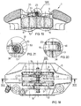
- the caliper body 2 comprises, integrally, an outer caliper half-body 4 and an inner caliper half-body 5, positioned on opposite sides of the braking band of the disk 3. At least two single-acting pistons 6 are guided for sliding in hydraulic braking cylinders disposed facing one another and formed integrally within the half-bodies 4 and 5. Bridge portions 7 extending parallel to the axis X-X of rotation of the disk 3 interconnect the two half-bodies 4 and 5.
- the disk brake unit 1 comprises at least one pair of identical and opposed pads 8 and 9 mounted on the caliper body 2 on opposite sides of the disk 3 and between the pistons 6.
- the pads 8, 9 comprise respective support plates 10 and 11 for supporting corresponding friction linings 12 and 13.
- the friction linings 12, 13 are fixed, in conventional manner, on respective faces or support surfaces 14 and 15 of the plates.
- the pads are mounted in the caliper body 2 with the corresponding friction linings 12 and 13 facing towards the disk 3 so that opposite faces or thrust surfaces 16 and 17 of the plates face towards the pistons 6.
- the plates have corresponding upper lug extensions or lugs 18 and 19 extending through a window 20 formed in an upper portion of the caliper body 2 between the half-bodies 4 and 5.
- the lugs have respective through-holes or slots 21 and 22.
- the lug In each pad, the lug is advantageously provided in a substantially central position relative to the longitudinal dimension of the pad. In the working position, the slot in the lug is disposed above the disk or, in other words, outside the disk so that it is above the region in which the pistons act ( Figures 2, 8 and 9).
- a pin 23 has a central portion of predominant length extending through the caliper body 2, through the window 20.
- the pin 23 is engaged through the slots 21 and 22 with clearance such that it secures the pads to the caliper body whilst allowing them to slide freely axially relative to the pin.
- the pin acts as a guide for the pads during the movement towards and away from the disk.
- the pin 23 has a tip end 24 and a head end 25 in guided engagement in the caliper body 2 on the sides on which the half-bodies 4 and 5 are disposed, respectively.
- the head end 25 is housed in abutment in a seat 26 formed in one half-body 4.
- a portion of the pin which is disposed far enough along the axis of the pin from the head end to project from the half-body 4 housing the head end 25, on the opposite side to the head end 25, has a seat for means for fixing the pin axially such as, for example, a transverse through-hole 27 in the pin for housing a split pin 28.
- the split pin 28 may have a portion projecting from the window 20 and bent against an upper surface 29 of the half-body 4 so as to prevent rotation of the pin 23 ( Figures 1 and 10).
- Each plate 10 (11) has, on opposite sides, lateral shoulders 30 and 31 constituting stop means for cooperating with facing first complementary stop means 32 formed in the downstream portion "O" of the caliper body 2 and second complementary stop means 33 formed in the upstream portion "I” of the caliper body 2. Both the first and the second complementary stop means are arranged tangentially relative to the disk.
- these first and second complementary stop means 32, 33 comprise opposed abutment surfaces defining laterally notches or grooves or, in other words, seats provided in the half-bodies 4 and 5 in positions facing the pistons 6.
- the disk brake unit 1 also comprises a single element, generally indicated 34, disposed between the pin 23 and the at least one pair of pads in order to keep the pads constantly suspended on the pin and simultaneously to urge each pad constantly both towards the first complementary stop means 32 and away from the braking disk 3 ( Figures 1, 2, 5, 6 and 7).
- the single element advantageously comprises first portions 35 for urging the pads 8 and 9 away from the braking disk 3 and at the same time, for constantly maintaining the suspension on the pin 23.
- the term "maintaining the suspension” is intended to define an action which affects the pads 8, 9 and, in particular, the friction linings 12, 13, urging them away from the pin 23, towards the disk 3 so as to bring the pin 23 into abutment with the upper portion of the surface defining the slot 21 (22) formed in the lug 18 (19).
- the single element 34 comprises second portions 36 for urging the pads 8, 9 towards the first complementary stop means 32.
- the single element 34 constantly urges the pads 8, 9 in the tangential direction "F" of the forward movement of the motor vehicle in a manner such that, upon braking, when the pads come into contact with the disk, the preloading provided by the single element prevents vibrations from arising, also facilitating the commencement of braking since the play between the plates and the pad seats in the caliper body is fully taken up by the single element, even before the braking action starts.
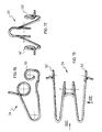
- the single element 34 is a wire spring, for example, made of steel spring wire.
- a configuration of the wire spring which ensures the desired simultaneous actions on the pads 8, 9 is a substantially "M"-shaped configuration which has two limbs constituting the first portions 35 and having first arms 37 and second arms 38 extending in different planes, as well as bent free ends constituting the second portions 36.
- the first and second arms are connected to one another by respective elbow portions 39.
- Each second arm advantageously has a curved portion 42 shaped like a leaf spring. This portion bears against the pad with at least two end portions 43 and 44 of the second arm 38 and against the pin 23 with an intermediate portion 45.
- the leaf-spring-shaped curved portion 42 thus preloads the suspension of the pad on the pin, ensuring that, during the vibrational stresses which occur before and during braking, accidental stresses on the pad tending to lift or move the pad away from its working position facing the braking band of the disk are balanced by the constant action of the leaf-spring-shaped curved portion.
- this curved portion 42 can move the friction lining 12 (13) away form the pin 23 (arrow "P" of Figure 4).
- the spring 34 also comprises hook-shaped bent end portions 46 for urging the pads 8, 9 (in the direction of the arrow "T") towards the complementary stop means 32, in a direction tangential to the disk.
- the hook-shaped portions 46 are advantageously arranged astride the upper edge of the plate 10 (11), so as to abut the outer surface defining the lug-like extension 18 (19) and, in particular, to abut portions 47 of the lug which extend substantially radially relative to the disk 3.
- the hook-shaped portions 46 preferably have parts 48 which are disposed substantially transversely relative to the plates and which can engage the edge 47 of the plate. With further advantage, the free end 49 of the hook 46 is bent onto the plate 10 (11) externally or, in other words, against the face 17 of the plate remote from the disk and facing the pistons 6 ( Figures 4 and 5).
- the spring comprises a coiled portion 40 which is fitted on the pin 23.
- a portion constituting a mounting lever 41 extends from the top of the coil.
- the pair of pads 8, 9 is inserted through the window 20 in the caliper body 2 so that each pad is housed in the respective seat defined laterally by the complementary stop means 32 and 33.
- This operation is facilitated by the provision of a temporary support surface 50 which is disposed in the half-bodies 4, 5 below the pistons 6 and which does not have the function of reacting to the braking forces but has the sole purpose of keeping the pads in the correct position during the assembly operations.
- the wire spring 34 is then brought alongside the pads, passing through the window 20. During the insertion of the spring through the window 20 and between the pads, it will be necessary to move the limbs 35 towards each other so that the distance between them is less than the distance between the plates 10, 11 of the pads. When the limbs 35 of the spring are released, portions of the second arms 38 abut the pads. In particular, the second arms abut a connecting region 51 between the support plates 10, 11 and the friction linings 12, 13 of the pads.
- the wire spring During the insertion of the wire spring through the window until it abuts the pads, it is necessary to pay particular attention to its orientation relative to the caliper body and to the direction of forward movement of the vehicle.
- the wire spring must be oriented in a manner such that its hook-shaped ends 46 face the upstream portion "I" of the caliper body.
- the pin 23 is then inserted.
- the pads are lifted from the temporary support surfaces 50, remaining suspended on the pin 23.
- the component directed towards the pistons keeps the pads constantly away from the disk and in abutment with the respective pistons when the brake unit is inactive.
- the spring acts as a separator so as always to permit mounting and removal of the disk or of the caliper body in the manner which will be described in greater detail below.
- the hook-shaped portions of the wire spring exert a force having a component directed towards the downstream portion of the caliper body, substantially in the same direction as the braking force and tangential to the disk.
- the force exerted by the hooks thus keeps the pads constantly in abutment with the complementary stop and braking-force reaction means formed in the downstream portion "O" of the caliper body, thus avoiding dead times necessary for taking up the play between the pad and the caliper body, ensuring quicker braking of the vehicle every time the brake is operated.
- This arrangement also avoids impacts between the plates and the caliper body, as well as vibrations and annoying whistles.
- the disk brake unit according to the present invention requires no tools for its assembly and the small assembly force required renders it also usable in racing equipment in which operation and maintenance times must be particularly short.
- a further advantage of the invention lies in its unusual structural simplicity which enables it to be produced at a very low cost.
- the calipers which are supported by forks, are positioned towards the outside of the motor-vehicle by virtue of the ability of the forks to pivot freely about their own axes so as to permit removal of the bulky wheel-rim.
- the new wheel provided with the disk or disks is then inserted until the caliper bodies are disposed in the space between the disks and the wheel rim.
- the caliper bodies are pivoted into alignment with the disks and the fitting of the wheel is completed.
- the braking bands of the disks reach their operative positions inside the caliper body only if the pads, which are floating on their pin, do not obstruct their insertion between the half-bodies. This is provided for safely by the above-described spring which constantly ensures that the pads are disposed in abutment with the pistons and that the necessary space between the half-bodies is free to receive the new disk.
- the hook of the single element 34 has a coiled portion 52.
- the wire spring exerts a constant force, even in the event of large movements of the pad ( Figures 11 to 17).
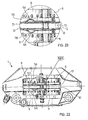
- each second arm is in abutment with an upper edge 55 of the respective plate 10, 11.
- the second arm has a lateral extension which extends outwardly relative to the disk and which abuts the edge of the plate, urging it constantly into suspension on the pin, even if the friction linings are completely worn out ( Figures 22 and 23).
- the caliper may be of the floating type and may be intended for vehicles such as, for example, motorcars, snowmobiles, motor-vehicles, motorcycles, and the like.
- a further subject of the present invention is a spare parts kit comprising at least a pair of pads, a pin and a single element for constantly maintaining the suspension of the pads on the pin and for constantly urging each pad both towards complementary stop means and away from the braking disk, as described above.
- a further subject of the invention is the single element which can constantly maintain the suspension of the pads on a pin and which can constantly urge each pad both towards complementary stop means and away from the braking disk, as described above.
Landscapes
- Engineering & Computer Science (AREA)
- General Engineering & Computer Science (AREA)
- Mechanical Engineering (AREA)
- Braking Arrangements (AREA)
Abstract
Description
Claims (20)
- A disk-brake unit (1) comprising a caliper body (2) extending astride a braking disk (3), at least one pair of pads (8, 9) facing the disk on opposite sides and restrained on the caliper body by suspension on a pin (23), each pad having a support plate (10, 11) for a friction lining (12, 13), and stop means (30) formed in the plates and facing respective complementary stop means (32) formed in the caliper body for restraining the pads in a direction tangential to the disk, characterized in that it comprises, between the pin and the at least one pair of pads, a single element (34) for constantly maintaining the suspension of the pads on the pin and simultaneously constantly urging each pad both towards the complementary stop means and away from the braking disk.
- A unit according to Claim 1, in which the at least one pair of pads is restrained on the pin by a substantially central portion (18, 19) of each pad.
- A unit according to Claim 1 or Claim 2, in which the pin is housed with clearance in slots (21, 22) provided in the central portions of the plates, these portions being disposed outside the disk.
- A unit according to Claim 1, in which the single element comprises first portions (35) which urge the pads away from the braking disk and constantly maintain the suspension on the pin, as well as second portions (36) which urge the pads towards the complementary stop means.
- A unit according to any one of the preceding claims, in which the single element is a wire spring (34).
- A unit according to Claim 5, in which the wire is steel spring wire.
- A unit according to Claim 5 or Claim 6, in which the spring is substantially "M"-shaped with two limbs (35) having respective first arms (37) and second arms (38) which extend in different planes, as well as respective bent free ends (36).
- A unit according to any one of Claims 5 to 7, in which the spring comprises a coiled portion (40) fitted on the pin.
- A unit according to Claim 8, in which a portion constituting a mounting lever (41) extends from the coil.
- A unit according to any one of Claims 7 to 9, in which the second arms have portions (43, 44) abutting the pads.
- A unit according to Claim 10, in which the second arms abut respective connecting regions (51) between the support plates and the friction linings of the pads.
- A unit according to Claim 10 or Claim 11, in which a portion (54) of each second arm abuts an upper edge of the respective plate.
- A unit according to any one of Claims 7 to 12, in which each second arm has a curved portion (42) shaped like a leaf spring for preloading the suspension of the plate on the pin so as to move the friction lining away from the pin.
- A unit according to any one of Claims 5 to 13, in which the spring has hook-shaped bent end portions (46, 48) for urging the pads towards the complementary stop means in a tangential direction.
- A unit according to Claim 14, in which the hook-shaped portions are disposed astride the plates.
- A unit according to Claim 15, in which the hook-shaped portions have parts (48) disposed substantially transversely relative to the plates.
- A unit according to any one of Claims 14 to 16, in which the end (49) of the hook is bent onto the plate externally.
- A unit according to any one of Claims 14 to 17, in which the hook has a coiled portion (52).
- A spare parts kit comprising at least a pair of pads (8, 9), a pin (23), and a single element (34) which can constantly maintain the suspension of the pads on the pin and can constantly urge each pad both towards complementary stop means and away from a braking disk (3), as described in any one of the preceding claims.
- A single element (34) which can constantly maintain the suspension of pads (8, 9) on a pin (23) and can constantly urge each pad both towards complementary stop means and away from a braking disk (3), as described in any one of Claims 1 to 18.
Priority Applications (7)
| Application Number | Priority Date | Filing Date | Title |
|---|---|---|---|
| AT00830294T ATE359453T1 (en) | 2000-04-18 | 2000-04-18 | A DISC BRAKE UNIT |
| EP00830294A EP1148265B1 (en) | 2000-04-18 | 2000-04-18 | A disk brake unit |
| DE60034310T DE60034310D1 (en) | 2000-04-18 | 2000-04-18 | A disc brake unit |
| AU2001256214A AU2001256214A1 (en) | 2000-04-18 | 2001-03-23 | Vehicle disk brake |
| PCT/EP2001/003313 WO2001079723A1 (en) | 2000-04-18 | 2001-03-23 | Vehicle disk brake |
| US10/257,743 US6957724B2 (en) | 2000-04-18 | 2001-03-23 | Vehicle disk brake |
| JP2001577089A JP2004501321A (en) | 2000-04-18 | 2001-03-23 | Disc brakes for vehicles |
Applications Claiming Priority (1)
| Application Number | Priority Date | Filing Date | Title |
|---|---|---|---|
| EP00830294A EP1148265B1 (en) | 2000-04-18 | 2000-04-18 | A disk brake unit |
Publications (2)
| Publication Number | Publication Date |
|---|---|
| EP1148265A1 true EP1148265A1 (en) | 2001-10-24 |
| EP1148265B1 EP1148265B1 (en) | 2007-04-11 |
Family
ID=8175293
Family Applications (1)
| Application Number | Title | Priority Date | Filing Date |
|---|---|---|---|
| EP00830294A Expired - Lifetime EP1148265B1 (en) | 2000-04-18 | 2000-04-18 | A disk brake unit |
Country Status (7)
| Country | Link |
|---|---|
| US (1) | US6957724B2 (en) |
| EP (1) | EP1148265B1 (en) |
| JP (1) | JP2004501321A (en) |
| AT (1) | ATE359453T1 (en) |
| AU (1) | AU2001256214A1 (en) |
| DE (1) | DE60034310D1 (en) |
| WO (1) | WO2001079723A1 (en) |
Cited By (3)
| Publication number | Priority date | Publication date | Assignee | Title |
|---|---|---|---|---|
| WO2010073277A1 (en) * | 2008-12-24 | 2010-07-01 | Freni Brembo S.P.A. | Wire spring for disc brake caliper and disc brake caliper |
| DE102011016831A1 (en) * | 2011-04-12 | 2012-10-18 | Lucas Automotive Gmbh | Disc brake for motor vehicle brake assembly, has resetting unit that is engaged to brake pad retaining pin such that resetting unit acts on brake disc of brake pad assembly, which has springs at side of opening of brake pad assembly |
| CN116710676A (en) * | 2020-12-15 | 2023-09-05 | 乐姆宝公开有限公司 | Brake bands for disc brake discs |
Families Citing this family (19)
| Publication number | Priority date | Publication date | Assignee | Title |
|---|---|---|---|---|
| JP4086827B2 (en) * | 2004-09-15 | 2008-05-14 | 曙ブレーキ工業株式会社 | Floating caliper type disc brake |
| US7267208B2 (en) * | 2004-12-14 | 2007-09-11 | Akebono Corporation | Retention spring for brake pressure pads |
| US8672100B2 (en) * | 2005-02-07 | 2014-03-18 | Hitachi, Ltd. | Cylinder apparatus and disk brake |
| GB0521326D0 (en) * | 2005-10-20 | 2005-11-30 | Bentley Motors Ltd | A pad retention device |
| JP4818250B2 (en) * | 2007-12-27 | 2011-11-16 | 日立オートモティブシステムズ株式会社 | Disc brake |
| KR20100065604A (en) * | 2008-12-08 | 2010-06-17 | 주식회사 만도 | Disk brake for vehicle |
| JP5454352B2 (en) * | 2010-05-20 | 2014-03-26 | 株式会社アドヴィックス | Disc brake device |
| US20120312642A1 (en) * | 2011-06-13 | 2012-12-13 | Bosco Jr Robert | Friction pad spreader, assembly including same and method of mounting thereof |
| DE102013216592B4 (en) * | 2013-01-31 | 2022-01-27 | Continental Teves Ag & Co. Ohg | Friction lining with a steel wire bow spring |
| JP6333012B2 (en) * | 2014-03-26 | 2018-05-30 | 日信工業株式会社 | Vehicle disc brake |
| CN104819229A (en) * | 2015-05-18 | 2015-08-05 | 安徽江淮汽车股份有限公司 | Fixed caliper disc brake |
| DE202016102686U1 (en) * | 2015-06-15 | 2016-06-23 | Knorr-Bremse Systeme für Nutzfahrzeuge GmbH | Disc brake for a commercial vehicle and brake pad set |
| DE102016004516A1 (en) * | 2016-04-13 | 2017-10-19 | Wabco Europe Bvba | Disc brake, in particular for commercial vehicles |
| DE102016010301A1 (en) | 2016-08-24 | 2018-03-01 | Lucas Automotive Gmbh | Fixed caliper disc brake with a guide element for returning a brake pad assembly |
| DE102016124310A1 (en) * | 2016-12-14 | 2018-06-14 | Knorr-Bremse Systeme für Nutzfahrzeuge GmbH | Disc brake for a commercial vehicle and brake pad set |
| DE102017001089A1 (en) | 2017-02-07 | 2018-08-09 | Lucas Automotive Gmbh | Fixed caliper disc brake with brake pad return element |
| FR3067688B1 (en) * | 2017-06-19 | 2019-08-09 | Faiveley Transport Amiens | RAILWAY BRAKING SYSTEM FOR RAILWAY VEHICLE |
| DE102018002886A1 (en) * | 2018-04-10 | 2019-10-10 | Lucas Automotive Gmbh | Brake pad arrangement for a disc brake of a vehicle brake system |
| JP7456885B2 (en) * | 2020-08-07 | 2024-03-27 | 曙ブレーキ工業株式会社 | disc brake device |
Citations (4)
| Publication number | Priority date | Publication date | Assignee | Title |
|---|---|---|---|---|
| DE2225178A1 (en) * | 1972-05-24 | 1974-01-17 | Teves Gmbh Alfred | PARTIAL DISC BRAKE |
| GB1364861A (en) * | 1971-05-11 | 1974-08-29 | Girling Ltd | Disc brakes |
| US5687817A (en) * | 1995-01-27 | 1997-11-18 | Tokico Ltd. | Disc brake |
| US5947234A (en) * | 1996-04-08 | 1999-09-07 | Aisin Seiki Kabushiki Kaisha | Disc brake |
Family Cites Families (5)
| Publication number | Priority date | Publication date | Assignee | Title |
|---|---|---|---|---|
| US3899051A (en) * | 1971-06-17 | 1975-08-12 | Citroen Sa | Disc brakes especially for automobiles |
| JPS528943Y2 (en) * | 1973-08-29 | 1977-02-24 | ||
| JPS5631531A (en) * | 1979-08-18 | 1981-03-30 | Sumitomo Electric Ind Ltd | Disc brake |
| DE3108113A1 (en) * | 1981-03-04 | 1982-09-16 | FAG Kugelfischer Georg Schäfer & Co, 8720 Schweinfurt | PARTIAL DISC BRAKE |
| GB2257483B (en) * | 1991-06-20 | 1995-04-26 | Tokico Ltd | Disk brake with return spring |
-
2000
- 2000-04-18 AT AT00830294T patent/ATE359453T1/en not_active IP Right Cessation
- 2000-04-18 DE DE60034310T patent/DE60034310D1/en not_active Expired - Fee Related
- 2000-04-18 EP EP00830294A patent/EP1148265B1/en not_active Expired - Lifetime
-
2001
- 2001-03-23 JP JP2001577089A patent/JP2004501321A/en active Pending
- 2001-03-23 WO PCT/EP2001/003313 patent/WO2001079723A1/en not_active Ceased
- 2001-03-23 AU AU2001256214A patent/AU2001256214A1/en not_active Abandoned
- 2001-03-23 US US10/257,743 patent/US6957724B2/en not_active Expired - Fee Related
Patent Citations (4)
| Publication number | Priority date | Publication date | Assignee | Title |
|---|---|---|---|---|
| GB1364861A (en) * | 1971-05-11 | 1974-08-29 | Girling Ltd | Disc brakes |
| DE2225178A1 (en) * | 1972-05-24 | 1974-01-17 | Teves Gmbh Alfred | PARTIAL DISC BRAKE |
| US5687817A (en) * | 1995-01-27 | 1997-11-18 | Tokico Ltd. | Disc brake |
| US5947234A (en) * | 1996-04-08 | 1999-09-07 | Aisin Seiki Kabushiki Kaisha | Disc brake |
Cited By (3)
| Publication number | Priority date | Publication date | Assignee | Title |
|---|---|---|---|---|
| WO2010073277A1 (en) * | 2008-12-24 | 2010-07-01 | Freni Brembo S.P.A. | Wire spring for disc brake caliper and disc brake caliper |
| DE102011016831A1 (en) * | 2011-04-12 | 2012-10-18 | Lucas Automotive Gmbh | Disc brake for motor vehicle brake assembly, has resetting unit that is engaged to brake pad retaining pin such that resetting unit acts on brake disc of brake pad assembly, which has springs at side of opening of brake pad assembly |
| CN116710676A (en) * | 2020-12-15 | 2023-09-05 | 乐姆宝公开有限公司 | Brake bands for disc brake discs |
Also Published As
| Publication number | Publication date |
|---|---|
| US6957724B2 (en) | 2005-10-25 |
| ATE359453T1 (en) | 2007-05-15 |
| AU2001256214A1 (en) | 2001-10-30 |
| WO2001079723A1 (en) | 2001-10-25 |
| DE60034310D1 (en) | 2007-05-24 |
| US20030136617A1 (en) | 2003-07-24 |
| EP1148265B1 (en) | 2007-04-11 |
| JP2004501321A (en) | 2004-01-15 |
Similar Documents
| Publication | Publication Date | Title |
|---|---|---|
| EP1148265B1 (en) | A disk brake unit | |
| EP1391628B1 (en) | Brake pad and brake caliper for disc brakes | |
| US4905796A (en) | Shoe mounted disc brake caliper assembly | |
| JPH05193466A (en) | Spot type disc brake | |
| US6971486B2 (en) | Caliper spring clip with axial force direction | |
| CN107850145B (en) | Disc brakes and brake lining sets for commercial vehicles | |
| US3917032A (en) | Single mount and guide pin for a caliper of a disc brake assembly | |
| KR101238254B1 (en) | Friction element and disc brake | |
| US4191278A (en) | Slidable support structure for a disc brake caliper | |
| GB2147673A (en) | Floating caliper spot-type disc brake | |
| CN110730876A (en) | Disc brake | |
| US4969540A (en) | Center loop anti-rattle spring | |
| JP4942865B2 (en) | Disc brake device and belt-like elastic device therefor | |
| KR101238255B1 (en) | Disk brake provided with a carrier of reduced size | |
| US4310076A (en) | Sliding caliper disc brake | |
| JP3085799B2 (en) | Disc brakes for vehicles | |
| JP4286349B2 (en) | Disc brake | |
| CN110741175B (en) | Disc brakes | |
| US20250146547A1 (en) | Disc Brake for a Utility Vehicle, and Brake Lining for a Disc Brake | |
| WO2002086344A1 (en) | Brake pad fixation for disc brakes | |
| CZ292148B6 (en) | Floating calliper disk brake for motor vehicles | |
| EP1650459B1 (en) | Device for retaining the friction linings of a brake disc | |
| JP2570814Y2 (en) | Disc brake | |
| US20250215943A1 (en) | Brake caliper of the floating type of a disc brake | |
| JPH0681968B2 (en) | Disc brakes for vehicles |
Legal Events
| Date | Code | Title | Description |
|---|---|---|---|
| PUAI | Public reference made under article 153(3) epc to a published international application that has entered the european phase |
Free format text: ORIGINAL CODE: 0009012 |
|
| AK | Designated contracting states |
Kind code of ref document: A1 Designated state(s): AT BE CH CY DE DK ES FI FR GB GR IE IT LI LU MC NL PT SE |
|
| AX | Request for extension of the european patent |
Free format text: AL;LT;LV;MK;RO;SI |
|
| 17P | Request for examination filed |
Effective date: 20020422 |
|
| AKX | Designation fees paid |
Free format text: AT BE CH CY DE DK ES FI FR GB GR IE IT LI LU MC NL PT SE |
|
| GRAP | Despatch of communication of intention to grant a patent |
Free format text: ORIGINAL CODE: EPIDOSNIGR1 |
|
| GRAS | Grant fee paid |
Free format text: ORIGINAL CODE: EPIDOSNIGR3 |
|
| GRAA | (expected) grant |
Free format text: ORIGINAL CODE: 0009210 |
|
| AK | Designated contracting states |
Kind code of ref document: B1 Designated state(s): AT BE CH CY DE DK ES FI FR GB GR IE IT LI LU MC NL PT SE |
|
| PG25 | Lapsed in a contracting state [announced via postgrant information from national office to epo] |
Ref country code: CH Free format text: LAPSE BECAUSE OF FAILURE TO SUBMIT A TRANSLATION OF THE DESCRIPTION OR TO PAY THE FEE WITHIN THE PRESCRIBED TIME-LIMIT Effective date: 20070411 Ref country code: LI Free format text: LAPSE BECAUSE OF FAILURE TO SUBMIT A TRANSLATION OF THE DESCRIPTION OR TO PAY THE FEE WITHIN THE PRESCRIBED TIME-LIMIT Effective date: 20070411 Ref country code: FI Free format text: LAPSE BECAUSE OF FAILURE TO SUBMIT A TRANSLATION OF THE DESCRIPTION OR TO PAY THE FEE WITHIN THE PRESCRIBED TIME-LIMIT Effective date: 20070411 |
|
| REG | Reference to a national code |
Ref country code: GB Ref legal event code: FG4D |
|
| REG | Reference to a national code |
Ref country code: CH Ref legal event code: EP |
|
| REG | Reference to a national code |
Ref country code: IE Ref legal event code: FG4D |
|
| REF | Corresponds to: |
Ref document number: 60034310 Country of ref document: DE Date of ref document: 20070524 Kind code of ref document: P |
|
| PG25 | Lapsed in a contracting state [announced via postgrant information from national office to epo] |
Ref country code: SE Free format text: LAPSE BECAUSE OF FAILURE TO SUBMIT A TRANSLATION OF THE DESCRIPTION OR TO PAY THE FEE WITHIN THE PRESCRIBED TIME-LIMIT Effective date: 20070711 |
|
| PG25 | Lapsed in a contracting state [announced via postgrant information from national office to epo] |
Ref country code: ES Free format text: LAPSE BECAUSE OF FAILURE TO SUBMIT A TRANSLATION OF THE DESCRIPTION OR TO PAY THE FEE WITHIN THE PRESCRIBED TIME-LIMIT Effective date: 20070722 |
|
| PG25 | Lapsed in a contracting state [announced via postgrant information from national office to epo] |
Ref country code: PT Free format text: LAPSE BECAUSE OF FAILURE TO SUBMIT A TRANSLATION OF THE DESCRIPTION OR TO PAY THE FEE WITHIN THE PRESCRIBED TIME-LIMIT Effective date: 20070911 |
|
| NLV1 | Nl: lapsed or annulled due to failure to fulfill the requirements of art. 29p and 29m of the patents act | ||
| REG | Reference to a national code |
Ref country code: CH Ref legal event code: PL |
|
| PG25 | Lapsed in a contracting state [announced via postgrant information from national office to epo] |
Ref country code: AT Free format text: LAPSE BECAUSE OF FAILURE TO SUBMIT A TRANSLATION OF THE DESCRIPTION OR TO PAY THE FEE WITHIN THE PRESCRIBED TIME-LIMIT Effective date: 20070411 |
|
| EN | Fr: translation not filed | ||
| PG25 | Lapsed in a contracting state [announced via postgrant information from national office to epo] |
Ref country code: BE Free format text: LAPSE BECAUSE OF FAILURE TO SUBMIT A TRANSLATION OF THE DESCRIPTION OR TO PAY THE FEE WITHIN THE PRESCRIBED TIME-LIMIT Effective date: 20070411 |
|
| PG25 | Lapsed in a contracting state [announced via postgrant information from national office to epo] |
Ref country code: NL Free format text: LAPSE BECAUSE OF FAILURE TO SUBMIT A TRANSLATION OF THE DESCRIPTION OR TO PAY THE FEE WITHIN THE PRESCRIBED TIME-LIMIT Effective date: 20070411 Ref country code: DK Free format text: LAPSE BECAUSE OF FAILURE TO SUBMIT A TRANSLATION OF THE DESCRIPTION OR TO PAY THE FEE WITHIN THE PRESCRIBED TIME-LIMIT Effective date: 20070411 Ref country code: DE Free format text: LAPSE BECAUSE OF NON-PAYMENT OF DUE FEES Effective date: 20071101 |
|
| PLBE | No opposition filed within time limit |
Free format text: ORIGINAL CODE: 0009261 |
|
| STAA | Information on the status of an ep patent application or granted ep patent |
Free format text: STATUS: NO OPPOSITION FILED WITHIN TIME LIMIT |
|
| 26N | No opposition filed |
Effective date: 20080114 |
|
| PG25 | Lapsed in a contracting state [announced via postgrant information from national office to epo] |
Ref country code: FR Free format text: LAPSE BECAUSE OF FAILURE TO SUBMIT A TRANSLATION OF THE DESCRIPTION OR TO PAY THE FEE WITHIN THE PRESCRIBED TIME-LIMIT Effective date: 20071207 Ref country code: GR Free format text: LAPSE BECAUSE OF FAILURE TO SUBMIT A TRANSLATION OF THE DESCRIPTION OR TO PAY THE FEE WITHIN THE PRESCRIBED TIME-LIMIT Effective date: 20070712 |
|
| PG25 | Lapsed in a contracting state [announced via postgrant information from national office to epo] |
Ref country code: IE Free format text: LAPSE BECAUSE OF NON-PAYMENT OF DUE FEES Effective date: 20070418 |
|
| PG25 | Lapsed in a contracting state [announced via postgrant information from national office to epo] |
Ref country code: FR Free format text: LAPSE BECAUSE OF FAILURE TO SUBMIT A TRANSLATION OF THE DESCRIPTION OR TO PAY THE FEE WITHIN THE PRESCRIBED TIME-LIMIT Effective date: 20070411 |
|
| PG25 | Lapsed in a contracting state [announced via postgrant information from national office to epo] |
Ref country code: MC Free format text: LAPSE BECAUSE OF NON-PAYMENT OF DUE FEES Effective date: 20070430 |
|
| PG25 | Lapsed in a contracting state [announced via postgrant information from national office to epo] |
Ref country code: CY Free format text: LAPSE BECAUSE OF FAILURE TO SUBMIT A TRANSLATION OF THE DESCRIPTION OR TO PAY THE FEE WITHIN THE PRESCRIBED TIME-LIMIT Effective date: 20070411 |
|
| PG25 | Lapsed in a contracting state [announced via postgrant information from national office to epo] |
Ref country code: LU Free format text: LAPSE BECAUSE OF NON-PAYMENT OF DUE FEES Effective date: 20070418 |
|
| PGFP | Annual fee paid to national office [announced via postgrant information from national office to epo] |
Ref country code: GB Payment date: 20120419 Year of fee payment: 13 |
|
| PGFP | Annual fee paid to national office [announced via postgrant information from national office to epo] |
Ref country code: IT Payment date: 20120416 Year of fee payment: 13 |
|
| GBPC | Gb: european patent ceased through non-payment of renewal fee |
Effective date: 20130418 |
|
| PG25 | Lapsed in a contracting state [announced via postgrant information from national office to epo] |
Ref country code: GB Free format text: LAPSE BECAUSE OF NON-PAYMENT OF DUE FEES Effective date: 20130418 |
|
| PG25 | Lapsed in a contracting state [announced via postgrant information from national office to epo] |
Ref country code: IT Free format text: LAPSE BECAUSE OF NON-PAYMENT OF DUE FEES Effective date: 20130418 |