EP1148244A2 - Variable displacement pump - Google Patents
Variable displacement pump Download PDFInfo
- Publication number
- EP1148244A2 EP1148244A2 EP01107865A EP01107865A EP1148244A2 EP 1148244 A2 EP1148244 A2 EP 1148244A2 EP 01107865 A EP01107865 A EP 01107865A EP 01107865 A EP01107865 A EP 01107865A EP 1148244 A2 EP1148244 A2 EP 1148244A2
- Authority
- EP
- European Patent Office
- Prior art keywords
- valve
- relief
- chamber
- passage
- pump
- Prior art date
- Legal status (The legal status is an assumption and is not a legal conclusion. Google has not performed a legal analysis and makes no representation as to the accuracy of the status listed.)
- Granted
Links
Images


Classifications
-
- F—MECHANICAL ENGINEERING; LIGHTING; HEATING; WEAPONS; BLASTING
- F04—POSITIVE - DISPLACEMENT MACHINES FOR LIQUIDS; PUMPS FOR LIQUIDS OR ELASTIC FLUIDS
- F04C—ROTARY-PISTON, OR OSCILLATING-PISTON, POSITIVE-DISPLACEMENT MACHINES FOR LIQUIDS; ROTARY-PISTON, OR OSCILLATING-PISTON, POSITIVE-DISPLACEMENT PUMPS
- F04C14/00—Control of, monitoring of, or safety arrangements for, machines, pumps or pumping installations
- F04C14/18—Control of, monitoring of, or safety arrangements for, machines, pumps or pumping installations characterised by varying the volume of the working chamber
- F04C14/22—Control of, monitoring of, or safety arrangements for, machines, pumps or pumping installations characterised by varying the volume of the working chamber by changing the eccentricity between cooperating members
- F04C14/223—Control of, monitoring of, or safety arrangements for, machines, pumps or pumping installations characterised by varying the volume of the working chamber by changing the eccentricity between cooperating members using a movable cam
- F04C14/226—Control of, monitoring of, or safety arrangements for, machines, pumps or pumping installations characterised by varying the volume of the working chamber by changing the eccentricity between cooperating members using a movable cam by pivoting the cam around an eccentric axis
-
- F—MECHANICAL ENGINEERING; LIGHTING; HEATING; WEAPONS; BLASTING
- F04—POSITIVE - DISPLACEMENT MACHINES FOR LIQUIDS; PUMPS FOR LIQUIDS OR ELASTIC FLUIDS
- F04C—ROTARY-PISTON, OR OSCILLATING-PISTON, POSITIVE-DISPLACEMENT MACHINES FOR LIQUIDS; ROTARY-PISTON, OR OSCILLATING-PISTON, POSITIVE-DISPLACEMENT PUMPS
- F04C2270/00—Control; Monitoring or safety arrangements
- F04C2270/50—Conditions before a throttle
Definitions
- the present invention relates to a variable displacement pump used in a power steering apparatus for a motor vehicle or the like.
- variable displacement pump described in Japanese Patent Application Laid-Open (JP-A) No. 8-200239 is used.
- This conventional variable displacement pump is directly rotated and driven by an engine of the motor vehicle.
- the variable displacement pump has a rotor within a cam ring moveably and displaceably fitted to an adapter ring fitting to a pump casing, thereby forming a pump chamber between the cam ring and the outer peripheral portion of the rotor.
- the cam ring is structured to be movable and displaceable within the adapter ring.
- An urging force maximizing the capacity of the pump chamber is applied to the cam ring by a spring.
- the first and second fluid pressure chambers are separately formed between the cam ring and the adapter ring.
- a switch valve controls the fluid pressure supplied to both of the fluid pressure chambers. This corresponds with the amount of discharge flow of a pressurized fluid from the pump chamber so as to move the cam ring.
- the capacity of the pump chamber is changed so as to control the discharge flow amount from the pump chamber.
- the amount of discharge flow is controlled to be large so as to obtain a large steering assist force when the motor vehicle stops or runs at a low speed, where the motor vehicle has a low rotational speed.
- the discharge flow amount is controlled to be equal to or less than a fixed amount, making the steering assist force small when the motor vehicle runs at a high speed, where the motor vehicle has a high rotational speed, whereby it is able to generate the steering assist force required for the power steering apparatus.
- a direct-drive type relief valve is provided in a pump discharge side passage so as to relieve the fluid pressure when the fluid pressure in the pump discharge side becomes too large due to a static turn steering state in the power steering apparatus being maintained or the like.
- the relief valve placed in the pump discharge side passage in the conventional art is the direct-drive type
- a change of relief pressure in accordance with a passing flow amount (a pressure override characteristic) is large.
- the passing flow amount tends to increase in accordance with an increase in the rotational speed, and reduce due to a reduction of an oil temperature. Accordingly, in a variable displacement pump with a direct-drive type relief valve in accordance with the conventional art, the used rotational speed and the oil temperature change affect it, making it impossible to obtain an inherently required relief pressure.
- An object of the present invention is to make it possible to set a stable relief pressure even when using conditions (a rotational speed and an oil temperature) are changed, when relieving an excessive fluid pressure in a pump discharge side, in a variable displacement pump.
- variable displacement pump comprised of a rotor rotated and driven while fixed to a pump shaft inserted to a pump casing and receiving a multiplicity of vanes in a groove so as to be movable in a radial direction. It contains an adapter ring fitted to a fitting hole in the pump casing and a cam ring fitted to the adapter ring so as to form a pump chamber between the cam ring and an outer peripheral portion of the rotor.
- the cam ring is movable and displaceable within the adapter ring and separately forms the first and second fluid pressure chambers between the cam ring and the adapter ring.
- a switch valve operated due to a pressure difference between an upstream side and a downstream side in a metering orifice provided in the pump discharge side passage controls the supply of fluid pressure to the first and second fluid pressure chambers in correspondence to a discharge flow amount of a pressurized fluid discharged from the pump chamber. This moves the cam ring and changes the capacity of the pump chamber, thereby making it possible to control the discharge flow amount discharged from the pump chamber.
- a relief valve relieves the excessive fluid pressure in the pump discharge side.
- the relief valve is constituted by a pilot drive type relief valve obtained by adding a pilot valve to a main valve.
- the fluid pressure in the downstream side of the metering orifice provided in the pump discharge side passage is applied to the pilot valve, and the main valve is capable of opening and closing the downstream side passage of the metering orifice with respect to a drain passage.
- variable displacement pump comprising a rotor rotated and driven while fixed to a pump shaft inserted to a pump casing and receiving a multiplicity of vanes in a groove so as to be movable in a radial direction.
- the cam ring contains an adapter ring fitted to a fitting hole in the pump casing and a cam ring fitted to the adapter ring so as to form a pump chamber between the cam ring and an outer peripheral portion of the rotor.
- the cam ring is movable and displaceable within the adapter ring and separately forms the first and second fluid pressure chambers between the cam ring and the adapter ring.
- a switch valve operated due to a pressure difference between an upstream side and a downstream side in a metering orifice provided in a pump discharge side passage controls the supply of fluid pressure to the first and second fluid pressure chambers in correspondence to a discharge flow amount of a pressurized fluid discharged from the pump chamber.
- a relief valve relieves the excessive fluid pressure in the pump discharge side.
- the relief valve is constituted by a pilot drive type relief valve obtained by adding a pilot valve to a main valve.
- the fluid pressure in the upstream side of the metering orifice provided in the pump discharge side passage is applied to the pilot valve, and the main valve is capable of opening and closing the upstream side passage of the metering orifice with respect to a drain passage.
- a variable displacement pump 10 is a vane pump corresponding to an oil pressure generating source of a hydraulic power steering apparatus for a motor vehicle.
- the pump 10 has a rotor 13 fixed in accordance with a serration to a pump shaft 12 inserted to a pump casing 11 so as to be rotated and driven as shown in FIG. 1 to FIG. 3.
- the pump casing 11 is structured by integrally combining a pump housing 11A with a cover 11B by using a bolt 14, and supports the pump shaft 12 via bearings 15A to 15C.
- the pump shaft 12 can be directly rotated and driven by an engine of a motor vehicle.
- the rotor 13 is structured such that vanes 17 are received in grooves 16 respectively provided at a multiple positions in a peripheral direction and the respective vanes 17 can be moved in a radial direction along the grooves 16.
- a pressure plate 18 and an adapter ring 19 are fitted in a laminated state to a fitting hole 20 in the pump housing 11A of the pump casing 11. These elements are fixed and held from a side portion by the cover 11B, in a state of being positioned in a peripheral direction by the supporting point pin 21 mentioned below. One end of the supporting point pin 21 is fitted and fixed to the cover 11B.
- a cam ring 22 is fitted to the above mentioned adapter ring 19 fitting to the pump housing 11A of the pump casing 11.
- the cam ring 22 surrounds the rotor 13 with an eccentricity with respect to the rotor 13. This forms a pump chamber 23 between the cam ring 22 and an outer peripheral portion of the rotor 13, between the pressure plate 18 and the cover 11B.
- a suction port 24 provided in the cover 11B is opened.
- a suction port 26 of the pump 10 is communicated with the suction port 24 via suction passages 25A and 25B provided in the housing 11A and the cover 11B.
- a discharge port 27 provided in the pressure plate 18 is opened to a discharge area in a downstream side in the rotor rotational direction of the pump chamber 23, and a discharge port 29 of the pump 10 is communicated with the discharge port 27 via a high pressure chamber 28A and a discharge passage 28B provided in the housing 11A.
- variable displacement pump 10 when the rotor 13 is rotated and driven by the pump shaft 12, and the vane 17 of the rotor 13 rotates by being pressed to the cam ring 22 by the centrifugal force, the followings occur.
- the variable displacement pump 10 expands a capacity surrounded by the adjacent vanes 17 and the cam ring 22 together with the rotation so as to suck a working fluid from the suction port 24.
- the variable displacement pump 10 reduces the capacity surrounded by the adjacent vanes 17 and the cam ring 22 together with the rotation so as to discharge the working fluid from the discharge port 27.
- variable displacement pump 10 has a discharge flow amount control apparatus 40 structured in the following manner (A) and a vane pressurizing apparatus 60 structured in the following manner (B).
- the discharge flow amount control apparatus 40 is structured such that the supporting point pin 21 is mounted vertically on the lowermost portion of the adapter ring 19 fixed to the pump casing 11. The lowest vertical portion of the cam ring 22 is supported by the supporting point pin 21, and the cam ring 22 can be swingably displaced within the adapter ring 19.
- the discharge flow amount control apparatus 40 can apply an urging force maximizing the capacity of the pump chamber 23 to the cam ring 22. This occurs when a spring 42 is received in the spring chamber 41 provided in the pump housing 11A constituting the pump casing 11 through a spring hole 19A provided in the adapter ring 19, so as to be in pressure contact with an outer peripheral portion of the cam ring 22.
- the spring 42 is backed up by a cap 41A attached to an opening portion of the spring chamber 41.
- the adapter ring 19 is structured such that a cam ring movement restricting stopper 19B is formed in a protruding shape in a part of an inner peripheral portion forming a second fluid pressure chamber 44B, whereby it is possible to restrict a moving limit of the cam ring 22 to minimize the capacity of the pump chamber 23 as mentioned below.
- the adapter ring 19 is structured such that a cam ring movement restricting stopper 19C is formed in a protruding shape in a part of an inner peripheral portion forming a first fluid pressure chamber 44A so as to restrict a moving limit of the cam ring 22 to maximize the capacity of the pump chamber 23.
- the discharge flow amount control apparatus 40 separately forms the first and second fluid pressure chambers 44A and 44B between the cam ring 22 and the adapter ring 19.
- the first fluid pressure chamber 44A and the second fluid pressure chamber 44B are separated between the cam ring 22 and the adapter 19 by the supporting point pin 21 and a seal member 45 provided at an axially symmetrical position.
- the first and second fluid pressure chambers 44A and 44B are sectioned both side portions between the cam ring 22 and the adapter ring 19 by the cover 11B and the pressure plate 18.
- the pressure plate 18 has a communicating groove 18A communicating the first fluid pressure chambers 44A separated into both sides of the stopper 19C with each other, and a communicating groove 18B communicating the second fluid pressure chambers 44B separated into both sides of the stopper 19B with each other, when the cam ring 22 collides and aligns with the cam ring movement restricting stoppers 19B and 19C in the adapter ring 19.
- the pressure fluid discharged from the pump chamber 23 and fed out to the high pressure chamber 28A of the pump housing 11A from the discharge port 27 of the pressure plate 18 is fed to the discharge passage 28B from a metering orifice 46 pieced in the pressure plate 18 via the second fluid pressure chamber 44B mentioned above, the spring chamber 41 mentioned above passing through the adapter ring 19 and a discharge communicating hole 100 notched in the fitting hole 20 of the pump housing 11A.
- the discharge flow amount control apparatus 40 increases and reduces an opening area of the metering orifice 46 open to the second fluid pressure chamber 44B by the side wall of the cam ring 22, in the discharge path of the pump 10 mentioned above, thereby forming a variable metering orifice.
- the opening degree of the orifice 46 is adjusted by the side wall in correspondence to the moving displacement of the cam ring 22.
- the discharge flow amount control apparatus 40 (1) then introduces the high fluid pressure of the high pressure chamber 28A before passing through the orifice 46 to the first fluid pressure chamber 44A via a first fluid pressure supply passage 47A (FIG.
- a switch valve apparatus 48 the pump housing 11A and a communicating passage 49 pierced in the adapter 19, and (2) introduces the reduced pressure after passing through the orifice 46 to the second fluid pressure chamber 44B in the manner mentioned above.
- the cam ring 22 moves against the urging force of the spring 42 mentioned above due to the differential force of the pressure applied to both of the fluid pressure chambers 44A and 44B, and changes the capacity of the pump chamber 23, thereby capable of controlling the discharge flow amount of the pump 10.
- the switch valve apparatus 48 is structured such that a spring 52 and a switch valve 53 are received in a valve receiving hole 51 pierced in the pump housing 11A, and the switch valve 53 urged by the spring 52 is supported by a cap 54 engaged with the pump housing 11A.
- the switch valve 53 has a switch valve body 55A and a valve body 55B, and is structured such that the first fluid pressure supply passage 47A is communicated with a pressurizing chamber 56A in the switch valve body 55A.
- the second fluid pressure chamber 44B is communicated with a back pressure chamber 56B in which another spring 52 of the valve body 55B is stored, via the pump housing 11A and a communicating passage 57 pieced in the adapter ring 19.
- a suction passage (a drain passage) 25A mentioned above is formed through a manner in a middle chamber 56C between the switch valve body 55A and the valve body 55B, and is communicated with a tank.
- the switch valve body 55A can open and close the pump housing 11A and the communicating passage 49 mentioned above pierced in the adapter ring 19.
- the switch valve body 55A sets the switch valve 53 to an original position shown in FIG. 2 due to the urging force of the spring 52. This closes the communicating passage 49 to the first fluid pressure chamber 44A by the switch valve body 55A.
- the switch valve body 55A moves the switch valve 53 due to the high pressure fluid applied to the pressurizing chamber 56A so as to open the communicating passage 49, thereby introducing the high pressure fluid to the first fluid pressure chamber 44A.
- a discharge flow amount characteristic of the pump 10 provided with the discharge flow amount control apparatus 40 is as follows.
- the throttle 49Aprovided in the communicating passage 49 communicates with the pressurizing chamber 56A of the switch valve apparatus 48 with the first fluid pressure chamber 44A.
- the throttle 57A in the communicating passage 57 communicates the second fluid pressure chamber 44B with the back pressure chamber 56B of the switch valve apparatus 48.
- the vane pressurizing apparatus 60 has ring-shaped oil grooves 61 and 62 on slidable contact surfaces of the pressure plate 18 and the side plate 20 with the groove 16, corresponding to both sides of the base portion 16A of the groove 16 receiving the vane 17 of the rotor 13.
- the high pressure chamber 28A of the pump chamber 23 in the pump housing 11A communicates with the oil groove 61 mentioned above via an oil hole 63 in the pressure plate 18.
- the pressure fluid discharged from the pump chamber 23 to the high pressure chamber 28A can be introduced to the base portion of the groove 16 for all the vanes 17 in the peripheral direction of the rotor 13 via the oil grooves 61 and 62 of the pressure plate 18 and the side plate 20, and can pressurize each of the vanes 17 toward the cam ring 22.
- the pump 10 presses the vane 17 to the cam ring 22 due to a centrifugal force at when beginning rotation. However, after the discharge pressure is generated, the pump 10 increases the contact pressure between the vane 17 and the cam ring 22 by the vane pressurizing apparatus 60, thereby capable of preventing the pressure fluid from inversely flowing.
- the pump 10 has a relief valve 70 which relieves the excessive fluid pressure in the pump discharge side between the high pressure chamber 28A and the suction passage (the drain passage) 25A.
- a lubricating oil supply passage 121 from the suction passage 25B toward the bearing 15C of the pump shaft 12 is pierced in the cover 11B.
- a lubricating oil return passage 122 returning from a peripheral portion of the bearing 15B of the pump shaft 12 to the suction passage 25A is pieced in the pump housing 11A.
- the relief valve 70 is structured as shown in FIG. 5.
- the relief valve 70 is structured in a pilot-drive type in which a pilot valve 72 is added to a main valve 71.
- the main valve 71 can open and close a downstream side passage of the metering orifice 46 provided in the pump discharge side passage, that is, a first valve chamber 73A with respect to the drain passage 25A.
- a fluid pressure in the downstream side of the metering orifice 46provided in the pump discharge side passage, and a fluid pressure of the second valve chamber 73B is applied to the pilot valve 72.
- the fluid pressure in the downstream side of the metering orifice 46 is applied to the pilot valve 72 via a throttle 130.
- the relief valve 70 shown in FIG. 5 has the following structures (a) to (c).
- the relief valve 70 is arranged in parallel to the switch valve 53 to control the movement of the cam ring 22.
- the relieving operation of the relief valve 70 does not directly influence the switching operation of the switch valve 53, and it is therefore possible to stably control the movement of the cam ring 22 by means of the switch valve 53.
- the second embodiment is different from the first embodiment when the fluid pressure in the upstream side of the metering orifice 46 in the pump discharge side passage is applied to the first valve chamber 73A and the second valve chamber 73B in the relief valve 70.
- the relief valve 70 as shown in FIG. 6 is structured in a pilot-drive type in which a pilot valve 72 is added to a main valve 71.
- the main valve 71 can open and close an upstream side passage of the metering orifice 46 provided in the pump discharge side passage, that is, a first valve chamber 73A with respect to the drain passage 25A.
- a fluid pressure in the upstream side of the metering orifice 46 provided in the pump discharge side passage, and further a fluid pressure of the second valve chamber 73B is applied to the pilot valve 72.
- the fluid pressure in the upstream side of the metering orifice 46 is applied to the pilot valve 72 via a throttle 140.
- the relief valve 70 shown in FIG. 6 has the following structures (a) to (c).
- the relief valve 70 is arranged in parallel to the switch valve 53 to control the movement of the cam ring 22.
- the relieving operation of the relief valve 70 does not directly influence the switching operation of the switch valve 53. It is therefore possible to stably control the movement of the cam ring 22 by means of the switch valve 53.
- variable displacement pump in the variable displacement pump, it is possible to set the stable relief pressure even when the using conditions (the rotational speed and the oil temperature) are changed when relieving the excessive fluid pressure in the pump discharge side.
Landscapes
- Engineering & Computer Science (AREA)
- Mechanical Engineering (AREA)
- General Engineering & Computer Science (AREA)
- Rotary Pumps (AREA)
- Details And Applications Of Rotary Liquid Pumps (AREA)
- Power Steering Mechanism (AREA)
- Safety Valves (AREA)
Abstract
Description
- The present invention relates to a variable displacement pump used in a power steering apparatus for a motor vehicle or the like.
- Conventionally, in order to assist a steering force by a hydraulic power steering apparatus for a motor vehicle, a variable displacement pump described in Japanese Patent Application Laid-Open (JP-A) No. 8-200239 is used. This conventional variable displacement pump is directly rotated and driven by an engine of the motor vehicle. The variable displacement pump has a rotor within a cam ring moveably and displaceably fitted to an adapter ring fitting to a pump casing, thereby forming a pump chamber between the cam ring and the outer peripheral portion of the rotor.
- In this conventional art, the cam ring is structured to be movable and displaceable within the adapter ring. An urging force maximizing the capacity of the pump chamber is applied to the cam ring by a spring. The first and second fluid pressure chambers are separately formed between the cam ring and the adapter ring. A switch valve controls the fluid pressure supplied to both of the fluid pressure chambers. This corresponds with the amount of discharge flow of a pressurized fluid from the pump chamber so as to move the cam ring. The capacity of the pump chamber is changed so as to control the discharge flow amount from the pump chamber. Accordingly, in this variable displacement pump, the amount of discharge flow is controlled to be large so as to obtain a large steering assist force when the motor vehicle stops or runs at a low speed, where the motor vehicle has a low rotational speed. The discharge flow amount is controlled to be equal to or less than a fixed amount, making the steering assist force small when the motor vehicle runs at a high speed, where the motor vehicle has a high rotational speed, whereby it is able to generate the steering assist force required for the power steering apparatus.
- In the conventional art, a direct-drive type relief valve is provided in a pump discharge side passage so as to relieve the fluid pressure when the fluid pressure in the pump discharge side becomes too large due to a static turn steering state in the power steering apparatus being maintained or the like.
- Since the relief valve placed in the pump discharge side passage in the conventional art is the direct-drive type, a change of relief pressure in accordance with a passing flow amount (a pressure override characteristic) is large. The passing flow amount tends to increase in accordance with an increase in the rotational speed, and reduce due to a reduction of an oil temperature. Accordingly, in a variable displacement pump with a direct-drive type relief valve in accordance with the conventional art, the used rotational speed and the oil temperature change affect it, making it impossible to obtain an inherently required relief pressure.
- An object of the present invention is to make it possible to set a stable relief pressure even when using conditions (a rotational speed and an oil temperature) are changed, when relieving an excessive fluid pressure in a pump discharge side, in a variable displacement pump.
- In accordance with the present invention, there is a variable displacement pump comprised of a rotor rotated and driven while fixed to a pump shaft inserted to a pump casing and receiving a multiplicity of vanes in a groove so as to be movable in a radial direction. It contains an adapter ring fitted to a fitting hole in the pump casing and a cam ring fitted to the adapter ring so as to form a pump chamber between the cam ring and an outer peripheral portion of the rotor. The cam ring is movable and displaceable within the adapter ring and separately forms the first and second fluid pressure chambers between the cam ring and the adapter ring. A switch valve operated due to a pressure difference between an upstream side and a downstream side in a metering orifice provided in the pump discharge side passage controls the supply of fluid pressure to the first and second fluid pressure chambers in correspondence to a discharge flow amount of a pressurized fluid discharged from the pump chamber. This moves the cam ring and changes the capacity of the pump chamber, thereby making it possible to control the discharge flow amount discharged from the pump chamber. A relief valve relieves the excessive fluid pressure in the pump discharge side. The relief valve is constituted by a pilot drive type relief valve obtained by adding a pilot valve to a main valve. The fluid pressure in the downstream side of the metering orifice provided in the pump discharge side passage is applied to the pilot valve, and the main valve is capable of opening and closing the downstream side passage of the metering orifice with respect to a drain passage.
- In accordance with the present invention, there is a variable displacement pump comprising a rotor rotated and driven while fixed to a pump shaft inserted to a pump casing and receiving a multiplicity of vanes in a groove so as to be movable in a radial direction.
- It contains an adapter ring fitted to a fitting hole in the pump casing and a cam ring fitted to the adapter ring so as to form a pump chamber between the cam ring and an outer peripheral portion of the rotor. The cam ring is movable and displaceable within the adapter ring and separately forms the first and second fluid pressure chambers between the cam ring and the adapter ring. A switch valve operated due to a pressure difference between an upstream side and a downstream side in a metering orifice provided in a pump discharge side passage controls the supply of fluid pressure to the first and second fluid pressure chambers in correspondence to a discharge flow amount of a pressurized fluid discharged from the pump chamber. This moves the cam ring and changes the capacity of the pump chamber, thereby making it possible to control the discharge flow amount discharged from the pump chamber. A relief valve relieves the excessive fluid pressure in the pump discharge side. The relief valve is constituted by a pilot drive type relief valve obtained by adding a pilot valve to a main valve. The fluid pressure in the upstream side of the metering orifice provided in the pump discharge side passage is applied to the pilot valve, and the main valve is capable of opening and closing the upstream side passage of the metering orifice with respect to a drain passage.
- The present invention will be more fully understood from the detailed description given below and from the accompanying drawings which should not be taken to be a limitation on the invention, but are for explanation and understanding only.
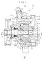
The drawings - FIG. 1 is a cross sectional view showing a variable displacement pump;
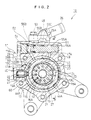
- FIG. 2 is a cross sectional view along a line II-II in FIG. 1;
- FIG. 3 is a cross sectional view along a line III-III in FIG. 1;
- FIG. 4 is a cross sectional view along a line IV-IV in FIG. 2;
- FIG. 5 is a hydraulic circuit view of a variable displacement pump; and
- FIG. 6 is a hydraulic circuit view showing another embodiment of the variable displacement pump.
-
- A
variable displacement pump 10 is a vane pump corresponding to an oil pressure generating source of a hydraulic power steering apparatus for a motor vehicle. Thepump 10 has arotor 13 fixed in accordance with a serration to apump shaft 12 inserted to apump casing 11 so as to be rotated and driven as shown in FIG. 1 to FIG. 3. Thepump casing 11 is structured by integrally combining apump housing 11A with a cover 11B by using abolt 14, and supports thepump shaft 12 viabearings 15A to 15C. Thepump shaft 12 can be directly rotated and driven by an engine of a motor vehicle. - The
rotor 13 is structured such thatvanes 17 are received ingrooves 16 respectively provided at a multiple positions in a peripheral direction and therespective vanes 17 can be moved in a radial direction along thegrooves 16. - A
pressure plate 18 and anadapter ring 19 are fitted in a laminated state to afitting hole 20 in thepump housing 11A of thepump casing 11. These elements are fixed and held from a side portion by the cover 11B, in a state of being positioned in a peripheral direction by the supportingpoint pin 21 mentioned below. One end of the supportingpoint pin 21 is fitted and fixed to the cover 11B. - A
cam ring 22 is fitted to the above mentionedadapter ring 19 fitting to thepump housing 11A of thepump casing 11. Thecam ring 22 surrounds therotor 13 with an eccentricity with respect to therotor 13. This forms apump chamber 23 between thecam ring 22 and an outer peripheral portion of therotor 13, between thepressure plate 18 and the cover 11B. In a suction area on an upstream side in a rotor rotational direction of thepump chamber 23, asuction port 24 provided in the cover 11B is opened. Asuction port 26 of thepump 10 is communicated with thesuction port 24 viasuction passages 25A and 25B provided in thehousing 11A and the cover 11B. On the contrary, adischarge port 27 provided in thepressure plate 18 is opened to a discharge area in a downstream side in the rotor rotational direction of thepump chamber 23, and adischarge port 29 of thepump 10 is communicated with thedischarge port 27 via ahigh pressure chamber 28A and adischarge passage 28B provided in thehousing 11A. - In the
variable displacement pump 10, when therotor 13 is rotated and driven by thepump shaft 12, and thevane 17 of therotor 13 rotates by being pressed to thecam ring 22 by the centrifugal force, the followings occur. In the upstream side in the rotor rotational direction of thepump chamber 23, thevariable displacement pump 10 expands a capacity surrounded by theadjacent vanes 17 and thecam ring 22 together with the rotation so as to suck a working fluid from thesuction port 24. In the downstream side in the rotor rotational direction of thepump chamber 23, thevariable displacement pump 10 reduces the capacity surrounded by theadjacent vanes 17 and thecam ring 22 together with the rotation so as to discharge the working fluid from thedischarge port 27. - The
variable displacement pump 10 has a discharge flowamount control apparatus 40 structured in the following manner (A) and avane pressurizing apparatus 60 structured in the following manner (B). - The discharge flow
amount control apparatus 40 is structured such that the supportingpoint pin 21 is mounted vertically on the lowermost portion of theadapter ring 19 fixed to thepump casing 11. The lowest vertical portion of thecam ring 22 is supported by the supportingpoint pin 21, and thecam ring 22 can be swingably displaced within theadapter ring 19. - The discharge flow
amount control apparatus 40 can apply an urging force maximizing the capacity of thepump chamber 23 to thecam ring 22. This occurs when aspring 42 is received in thespring chamber 41 provided in thepump housing 11A constituting thepump casing 11 through aspring hole 19A provided in theadapter ring 19, so as to be in pressure contact with an outer peripheral portion of thecam ring 22. Thespring 42 is backed up by acap 41A attached to an opening portion of thespring chamber 41. In this case, theadapter ring 19 is structured such that a cam ring movement restricting stopper 19B is formed in a protruding shape in a part of an inner peripheral portion forming a secondfluid pressure chamber 44B, whereby it is possible to restrict a moving limit of thecam ring 22 to minimize the capacity of thepump chamber 23 as mentioned below. Theadapter ring 19 is structured such that a cam ringmovement restricting stopper 19C is formed in a protruding shape in a part of an inner peripheral portion forming a first fluid pressure chamber 44A so as to restrict a moving limit of thecam ring 22 to maximize the capacity of thepump chamber 23. - The discharge flow
amount control apparatus 40 separately forms the first and secondfluid pressure chambers 44A and 44B between thecam ring 22 and theadapter ring 19. The first fluid pressure chamber 44A and the secondfluid pressure chamber 44B are separated between thecam ring 22 and theadapter 19 by the supportingpoint pin 21 and aseal member 45 provided at an axially symmetrical position. At this time, the first and secondfluid pressure chambers 44A and 44B are sectioned both side portions between thecam ring 22 and theadapter ring 19 by the cover 11B and thepressure plate 18. Thepressure plate 18 has a communicatinggroove 18A communicating the first fluid pressure chambers 44A separated into both sides of thestopper 19C with each other, and a communicatinggroove 18B communicating the secondfluid pressure chambers 44B separated into both sides of the stopper 19B with each other, when thecam ring 22 collides and aligns with the cam ringmovement restricting stoppers 19B and 19C in theadapter ring 19. - In the discharge path of the
pump 10 mentioned above, the pressure fluid discharged from thepump chamber 23 and fed out to thehigh pressure chamber 28A of thepump housing 11A from thedischarge port 27 of thepressure plate 18 is fed to thedischarge passage 28B from ametering orifice 46 pieced in thepressure plate 18 via the secondfluid pressure chamber 44B mentioned above, thespring chamber 41 mentioned above passing through theadapter ring 19 and adischarge communicating hole 100 notched in thefitting hole 20 of thepump housing 11A. - The discharge flow
amount control apparatus 40 increases and reduces an opening area of themetering orifice 46 open to the secondfluid pressure chamber 44B by the side wall of thecam ring 22, in the discharge path of thepump 10 mentioned above, thereby forming a variable metering orifice. The opening degree of theorifice 46 is adjusted by the side wall in correspondence to the moving displacement of thecam ring 22. The discharge flow amount control apparatus 40 (1) then introduces the high fluid pressure of thehigh pressure chamber 28A before passing through theorifice 46 to the first fluid pressure chamber 44A via a first fluidpressure supply passage 47A (FIG. 4), aswitch valve apparatus 48, thepump housing 11A and a communicatingpassage 49 pierced in theadapter 19, and (2) introduces the reduced pressure after passing through theorifice 46 to the secondfluid pressure chamber 44B in the manner mentioned above. Thecam ring 22 moves against the urging force of thespring 42 mentioned above due to the differential force of the pressure applied to both of thefluid pressure chambers 44A and 44B, and changes the capacity of thepump chamber 23, thereby capable of controlling the discharge flow amount of thepump 10. - The
switch valve apparatus 48 is structured such that aspring 52 and aswitch valve 53 are received in avalve receiving hole 51 pierced in thepump housing 11A, and theswitch valve 53 urged by thespring 52 is supported by acap 54 engaged with thepump housing 11A. Theswitch valve 53 has aswitch valve body 55A and avalve body 55B, and is structured such that the first fluidpressure supply passage 47A is communicated with a pressurizingchamber 56A in theswitch valve body 55A. The secondfluid pressure chamber 44B is communicated with aback pressure chamber 56B in which anotherspring 52 of thevalve body 55B is stored, via thepump housing 11A and a communicatingpassage 57 pieced in theadapter ring 19. A suction passage (a drain passage) 25A mentioned above is formed through a manner in amiddle chamber 56C between theswitch valve body 55A and thevalve body 55B, and is communicated with a tank. Theswitch valve body 55A can open and close thepump housing 11A and the communicatingpassage 49 mentioned above pierced in theadapter ring 19. In a low rotational range with a low discharge pressure of thepump 10, theswitch valve body 55A sets theswitch valve 53 to an original position shown in FIG. 2 due to the urging force of thespring 52. This closes the communicatingpassage 49 to the first fluid pressure chamber 44A by theswitch valve body 55A. In a middle and high rotational range of thepump 10, theswitch valve body 55A moves theswitch valve 53 due to the high pressure fluid applied to the pressurizingchamber 56A so as to open the communicatingpassage 49, thereby introducing the high pressure fluid to the first fluid pressure chamber 44A. - Accordingly, a discharge flow amount characteristic of the
pump 10 provided with the discharge flowamount control apparatus 40 is as follows. - (1) In a low speed running range of a motor vehicle in which
the rotational speed of the
pump 10 is low, the pressure of the fluid discharged from thepump chamber 23 to the pressurizingchamber 56A of theswitch valve apparatus 48 is still low. Thus, theswitch valve 53 is positioned at the original position and thecam ring 22 maintains the original state urged by thespring 42. Accordingly, the discharge flow amount of thepump 10 is increased in proportion to the rotational speed. - (2) When the pressure of the fluid discharged from the
pump chamber 23 to the pressurizingchamber 56A of theswitch valve apparatus 48 becomes high due to an increase of the rotational speed of thepump 10, theswitch valve apparatus 48 moves theswitch valve 53 against the urging force of thespring 52 so as to open the communicatingpassage 49 and introduce the high pressure fluid to the first fluid pressure chamber 44A. Thecam ring 22 moves due to the differential pressure applied to the first fluid pressure chamber 44A and the secondfluid pressure chamber 44B so as to gradually reduce the capacity of thepump chamber 23. The discharge flow amount of thepump 10 can cancel the flow amount increase caused by the increase of the rotational speed and the flow amount reduction caused by the reduction of the capacity in thepump chamber 23 with respect to the increase of the rotational speed, so as to maintain a fixed large flow amount. - (3) When the rotational speed of the
pump 10 is continuously increased more and thecam ring 22 is further moved, whereby thecam ring 22 presses thespring 42 at over a fixed amount, the side wall of thecam ring 22 starts throttling an open area of theorifice 46 in the middle portion of the discharge path from thepump chamber 23. Accordingly, the discharge flow amount pressure fed to thedischarge passage 28B of thepump 10 is reduced in proportion to the throttling amount of theorifice 46. - (4) When reaching a high speed drive range of the motor
vehicle in which the rotational speed of the
pump 10 is over a fixed value, thecam ring 22 reaches a moving limit where thecam ring 22 collides and aligns with the stopper 19B of theadapter ring 19. The throttling amount of theorifice 46 generated by the side wall of thecam ring 22 becomes maximum, and the discharge flow amount of thepump 10 maintains a fixed small flow amount. -
- In the discharge flow
amount control apparatus 40, the throttle 49Aprovided in the communicatingpassage 49 communicates with the pressurizingchamber 56A of theswitch valve apparatus 48 with the first fluid pressure chamber 44A. Thethrottle 57A in the communicatingpassage 57 communicates the secondfluid pressure chamber 44B with theback pressure chamber 56B of theswitch valve apparatus 48. - The
vane pressurizing apparatus 60 has ring-shapedoil grooves pressure plate 18 and theside plate 20 with thegroove 16, corresponding to both sides of thebase portion 16A of thegroove 16 receiving thevane 17 of therotor 13. Thehigh pressure chamber 28A of thepump chamber 23 in thepump housing 11A communicates with theoil groove 61 mentioned above via anoil hole 63 in thepressure plate 18. The pressure fluid discharged from thepump chamber 23 to thehigh pressure chamber 28A can be introduced to the base portion of thegroove 16 for all thevanes 17 in the peripheral direction of therotor 13 via theoil grooves pressure plate 18 and theside plate 20, and can pressurize each of thevanes 17 toward thecam ring 22. - The
pump 10 presses thevane 17 to thecam ring 22 due to a centrifugal force at when beginning rotation. However, after the discharge pressure is generated, thepump 10 increases the contact pressure between thevane 17 and thecam ring 22 by thevane pressurizing apparatus 60, thereby capable of preventing the pressure fluid from inversely flowing. - The
pump 10 has arelief valve 70 which relieves the excessive fluid pressure in the pump discharge side between thehigh pressure chamber 28A and the suction passage (the drain passage) 25A. In thepump 10, a lubricatingoil supply passage 121 from the suction passage 25B toward thebearing 15C of thepump shaft 12 is pierced in the cover 11B. A lubricatingoil return passage 122 returning from a peripheral portion of the bearing 15B of thepump shaft 12 to thesuction passage 25A is pieced in thepump housing 11A. - In the
pump 10, therelief valve 70 is structured as shown in FIG. 5. - The
relief valve 70 is structured in a pilot-drive type in which apilot valve 72 is added to amain valve 71. Themain valve 71 can open and close a downstream side passage of themetering orifice 46 provided in the pump discharge side passage, that is, afirst valve chamber 73A with respect to thedrain passage 25A. A fluid pressure in the downstream side of the metering orifice 46provided in the pump discharge side passage, and a fluid pressure of thesecond valve chamber 73B is applied to thepilot valve 72. At this time, the fluid pressure in the downstream side of themetering orifice 46 is applied to thepilot valve 72 via athrottle 130. Then, therelief valve 70 shown in FIG. 5 has the following structures (a) to (c). - (a) The
relief valve 70 has themain valve 71 slidably within thevalve chamber 73, and applies the fluid pressure in the downstream side of themetering orifice 46 provided in the discharge side passage of thepump 10 to thefirst valve chamber 73A. Thefirst valve chamber 73A is defined in one end side of thevalve chamber 73 with respect to themain valve 71 via apassage 131. Therelief valve 70 applies the fluid pressure in the downstream side of themetering orifice 46 to thesecond valve chamber 73B defined in another end side of thevalve chamber 73 with respect to themain valve 71 via the passage 131 (the throttle 130). Therelief valve 70 has afirst relief passage 74A communicating thefirst valve chamber 73A with thedrain passage 25A in thevalve chamber 73. Therelief valve 70 has afirst spring 75A (first urging means) urging themain valve 71 to a side of thefirst valve chamber 73A so as to set themain valve 71 to a close position of thefirst relief passage 74A. - (b) The
relief valve 70 hassecond relief passages second valve chamber 73B with thedrain passage 25A in themain valve 71. Therelief valve 70 has apilot valve 72 opening and closing thesecond relief passages second valve chamber 73B to thedrain passage 25A within thesecond relief passages second spring 75B (second urging means) sets thepilot valve 72 to a close position (avalve seat 76A) of thesecond relief passages valve holder 75C within themain valve 71. - (c) The
relief valve 70 is structured such that when the fluid pressure in the pump discharge side becomes excessive due to a continuous static turn steering state generated by the power steering apparatus in which thepump 10 is used, or the like, and the fluid pressure of thesecond valve chamber 73B connected to the discharge passage in the downstream side of themetering orifice 46 reaches the relief set pressure, the fluid pressure of thesecond valve chamber 73B opens thepilot valve 72 against thesecond spring 75B. It is possible to relieve the fluid pressure in thesecond valve chamber 73B from thesecond relief passages drain passage 25A so as to open themain valve 71 against thefirst spring 75A due to the fluid pressure of thefirst valve chamber 73A under the condition that the fluid pressure of thesecond value chamber 73B is reduced by this relief. It is possible to relieve the fluid pressure of thefirst valve chamber 73A from thefirst relief passage 74A to thedrain passage 25A. Therefore, it is possible to relieve the excessive fluid pressure in the pump discharge side. -
- In accordance with the
relief valve 70 shown in FIG. 5, therelief valve 70 is arranged in parallel to theswitch valve 53 to control the movement of thecam ring 22. The relieving operation of therelief valve 70 does not directly influence the switching operation of theswitch valve 53, and it is therefore possible to stably control the movement of thecam ring 22 by means of theswitch valve 53. - In accordance with the present embodiment, the following operations can be obtained.
- (1) The
relief valve 70 placed in the pump discharge side passage is set to the pilot-drive type. In thisrelief valve 70, a change of the relief pressure due to the passing flow amount (a pressure override characteristic) is small. It is therefore possible to set a stable relief pressure even when the passing flow amount is changed in accordance with the change of the using conditions (a rotational speed and an oil temperature). - (2) The
throttle 130 is provided in the passage applying the fluid pressure to thepilot valve 72 constituting therelief valve 70. Accordingly, it is possible to avoid a rapid pressure change of the fluid pressure applied to thepilot valve 72 so as to prevent a chattering, and it is possible to prevent a sound and a vibration in therelief valve 70. -
- The second embodiment is different from the first embodiment when the fluid pressure in the upstream side of the
metering orifice 46 in the pump discharge side passage is applied to thefirst valve chamber 73A and thesecond valve chamber 73B in therelief valve 70. - The
relief valve 70 as shown in FIG. 6 is structured in a pilot-drive type in which apilot valve 72 is added to amain valve 71. Themain valve 71 can open and close an upstream side passage of themetering orifice 46 provided in the pump discharge side passage, that is, afirst valve chamber 73A with respect to thedrain passage 25A. A fluid pressure in the upstream side of themetering orifice 46 provided in the pump discharge side passage, and further a fluid pressure of thesecond valve chamber 73B is applied to thepilot valve 72. At this time, the fluid pressure in the upstream side of themetering orifice 46 is applied to thepilot valve 72 via athrottle 140. Then, therelief valve 70 shown in FIG. 6 has the following structures (a) to (c). - (a) The
relief valve 70 has themain valve 71 slidably within thevalve chamber 73, and applies the fluid pressure in the upstream side of themetering orifice 46 provided in the discharge side passage of thepump 10 to thefirst valve chamber 73A. Thefirst valve chamber 73A is defined in one end side of thevalve chamber 73 with respect to themain valve 71 via apassage 141. Therelief valve 70 applies the fluid pressure in the upstream side of themetering orifice 46 to thesecond valve chamber 73B defined in another end side of thevalve chamber 73 with respect to themain valve 71 via the passage 141 (the throttle 140). Therelief valve 70 has afirst relief passage 74A communicating thefirst valve chamber 73A with thedrain passage 25A in thevalve chamber 73. Therelief valve 70 has afirst spring 75A (first urging means) urging themain valve 71 to a side of thefirst valve chamber 73A so as to set themain valve 71 to a close position of thefirst relief passage 74A. - (b) The
relief valve 70 hassecond relief passages second valve chamber 73B with thedrain passage 25A in themain valve 71. Therelief valve 70 has apilot valve 72 opening and closing thesecond relief passages second valve chamber 73B to thedrain passage 25A within thesecond relief passages second spring 75B (second urging means) sets thepilot valve 72 to a close position (avalve seat 76A) of thesecond relief passages valve holder 75C within themain valve 71. - (c) The
relief valve 70 is structured such that when the fluid pressure in the pump discharge side becomes excessive due to a continuous static turn steering state generated by the power steering apparatus in which thepump 10 is used, or the like, and the fluid pressure of thesecond valve chamber 73B connected to the discharge passage in the upstream side of themetering orifice 46 reaches the relief set pressure and the fluid pressure of thesecond valve chamber 73B opens thepilot valve 72 against thesecond spring 75B. It is possible to relieve the fluid pressure of thesecond valve chamber 73B from thesecond relief passages drain passage 25A so as to open themain valve 71 against thefirst spring 75A due to the fluid pressure of thefirst valve chamber 73A under the condition that the fluid pressure of thesecond valve chamber 73B is reduced by this relief. It is possible to relieve the fluid pressure of thefirst valve chamber 73A from thefirst relief passage 74A to thedrain passage 25A. It is therefore possible to relieve the excessive fluid pressure in the pump discharge side. -
- In accordance with the
relief valve 70 shown in FIG. 6, therelief valve 70 is arranged in parallel to theswitch valve 53 to control the movement of thecam ring 22. The relieving operation of therelief valve 70 does not directly influence the switching operation of theswitch valve 53. It is therefore possible to stably control the movement of thecam ring 22 by means of theswitch valve 53. - In accordance with the present embodiment, the following operations can be obtained.
- (1) The
relief valve 70 placed in the pump discharge side passage is set to the pilot-drive type. In thisrelief valve 70, a change of the relief pressure due to the passing flow amount (a pressure override characteristic) is small. It is therefore possible to set a stable relief pressure even when the passing flow amount is changed in accordance with the change of the using conditions (a rotational speed and an oil temperature). - (2) The
throttle 140 is provided in the passage applying the fluid pressure to thepilot valve 72 constituting therelief valve 70. Accordingly, it is possible to avoid a rapid pressure change of the fluid pressure applied to thepilot valve 72 so as to prevent a chattering, and it is possible to prevent a sound and a vibration in therelief valve 70. -
- As heretofore explained, embodiments of the present invention have been described in detail with reference to the drawings. However, the specific configurations of the present invention are not limited to the embodiments but those having a modification of the design within the range of the present invention are also included in the present invention.
- In accordance with the present invention, in the variable displacement pump, it is possible to set the stable relief pressure even when the using conditions (the rotational speed and the oil temperature) are changed when relieving the excessive fluid pressure in the pump discharge side.
- Although the invention has been illustrated and described with respect to several exemplary embodiments thereof, it should be understood by those skilled in the art that the foregoing and various other changes, omissions and additions may be made to the present invention without departing from the spirit and scope thereof. Therefore, the present invention should not be understood as limited to the specific embodiment set out above, but should be understood to include all possible embodiments which can be embodied within a scope encompassed and equivalents thereof with respect to the features set out in the appended claims.
Claims (8)
- A variable displacement pump comprising:a rotor fixable to a pump shaft inserted to a pump casing and receiving a plurality vanes in a groove so as to be movable in a radial direction, the rotor being rotatable and drivable;an adapter ring fitted to a fitting hole in the pump casing;a cam ring fitted to the adapter ring so as to form a pump chamber between the cam ring and an outer peripheral portion of the rotor, being movable and displaceable within the adapter ring and separately forming first and second fluid pressure chambers between the cam ring and the adapter ring;a switch valve operated due to a pressure difference between an upstream side and a downstream side in a metering orifice provided in a pump discharge side passage, and controlling the amount of fluid pressure supplied to the first and second fluid pressure chambers in correspondence to a discharge flow amount of a pressurized fluid discharged from the pump chamber so as to move the cam ring and change a capacity of the pump chamber, thereby making it possible to control the discharge flow amount discharged from the pump chamber; anda relief valve relieving excessive fluid pressure in the pump discharge side,wherein said relief valve is constituted by a pilot drive type relief valve comprising a pilot valve to a main valve, the fluid pressure in the downstream side of the metering orifice provided in the pump discharge side passage is applied to the pilot valve, and the main valve is capable of opening and closing the downstream side passage of the metering orifice with respect to a drain passage.
- A variable displacement pump as claimed in claim 1, wherein the fluid pressure in the downstream side of the metering orifice provided in said pump discharge side passage is applied to the pilot valve via the throttle.
- A variable displacement pump comprising:a rotor fixable to a pump shaft inserted to a pump casing and receiving a plurality of vanes in a groove so as to be movable in a radial direction, the rotor being rotatable and drivable;an adapter ring fitted to a fitting hole in the pump casing;a cam ring fitted to the adapter ring so as to form a pump chamber between the cam ring and an outer peripheral portion of the rotor, being movable and displaceable within the adapter ring and separately forming first and second fluid pressure chambers between the cam ring and the adapter ring;a switch valve operated due to a pressure difference between an upstream side and a downstream side in a metering orifice provided in a pump discharge side passage, and controlling the amount of fluid pressure supplied to the first and second fluid pressure chambers in correspondence to a discharge flow amount of a pressurized fluid discharged from the pump chamber so as to move the cam ring and change a capacity of the pump chamber, thereby making it possible to control the discharge flow amount discharged from the pump chamber; anda relief valve relieving excessive fluid pressure in the pump discharge side,wherein said relief valve is constituted by a pilot drive type relief valve comprising a pilot valve to a main valve, the fluid pressure in the upstream side of the metering orifice provided in the pump discharge side passage is applied to the pilot valve, and the main valve is capable of opening and closing the upstream side passage of the metering orifice with respect to a drain passage.
- A variable displacement pump as claimed in claim 1, wherein the fluid pressure in the upstream side of the metering orifice provided in said pump discharge side passage is applied to the pilot valve via the throttle.
- A variable displacement pump as claimed in claim 1, wherein said relief valve is structured such that a main valve is slidably disposed within a valve chamber, a first valve chamber is defined in one end side of the valve chamber with respect to the main valve, a fluid pressure in the downstream side of said metering orifice is applied to said first valve chamber, a second valve chamber is defined in another end side with respect to said main valve, the fluid pressure in the downstream side of said metering orifice is also applied to said second valve chamber, a first relief passage communicating said first valve chamber with the drain passage is provided in the valve chamber, and first urging means urging the main valve to a side of the first valve chamber so as to set the main valve to a close position of the first relief passage, and
wherein said relief valve has a second relief passage communicating the second valve chamber with the drain passage which is provided in the main valve, a pilot valve opening and closing said second relief passage so as to allow only a flow of the fluid from the second valve chamber to the drain passage provided within said second relief passage, and second urging means setting said pilot valve to a close position of the second relief passage in accordance with a relief set pressure, and a valve holder are provided within the main valve. - A variable displacement pump as claimed in claim 2, wherein said relief valve is structured such that a main valve is slidably disposed within a valve chamber, a first valve chamber is defined in one end side of the valve chamber with respect to the main valve, a fluid pressure in the downstream side of said metering orifice is applied to said first valve chamber, a second valve chamber is defined in another end side with respect to said main valve, the fluid pressure in the downstream side of said metering orifice is also applied to said second valve chamber, a first relief passage communicating said first valve chamber with the drain passage is provided in the valve chamber, and first urging means urging the main valve to a side of the first valve chamber so as to set the main valve to a close position of the first relief passage, and
wherein said relief valve is structured such that a second relief passage communicating the second valve chamber with the drain passage is provided in the main valve, a pilot valve opening and closing said second relief passage so as to allow only a flow of the fluid from the second valve chamber to the drain passage is provided within said second relief passage, and second urging means setting said pilot valve to a close position of the second relief passage in accordance with a relief set pressure, and a valve holder are provided within the main valve. - A variable displacement pump as claimed in claim 3, wherein said relief valve is structured such that a main valve is slidably disposed within a valve chamber, a first valve chamber is defined in one end side of the valve chamber with respect to the main valve, fluid pressure in the downstream side of said metering orifice is applied to said first valve chamber, a second valve chamber is defined in another end side with respect to said main valve, the fluid pressure in the downstream side of said metering orifice is also applied to said second valve chamber, a first relief passage communicating said first valve chamber with the drain passage is provided in the valve chamber, and first urging means urging the main valve to a side of the first valve chamber so as to set the main valve to a close position of the first relief passage, and
wherein said relief valve is structured such that a second relief passage communicating the second valve chamber with the drain passage is provided in the main valve, a pilot valve opening and closing said second relief passage so as to allow only a flow of the fluid from the second valve chamber to the drain passage is provided within said second relief passage, and second urging means setting said pilot valve to a close position of the second relief passage in accordance with a relief set pressure, and a valve holder are provided within the main valve. - A variable displacement pump as claimed in claim 4, wherein said relief valve is structured such that a main valve is slidably disposed within a valve chamber, a first valve chamber is defined in one end side of the valve chamber with respect to the main valve, a fluid pressure in the downstream side of said metering orifice is applied to said first valve chamber, a second valve chamber is defined in another end side with respect to said main valve, the fluid pressure in the downstream side of said metering orifice is also applied to said second valve chamber, a first relief passage communicating said first valve chamber with the drain passage is provided in the valve chamber, and first urging means urging the main valve to a side of the first valve chamber so as to set the main valve to a close position of the first relief passage, and
wherein said relief valve is structured such that a second relief passage communicating the second valve chamber with the drain passage is provided in the main valve, a pilot valve opening and closing said second relief passage so as to allow only a flow of the fluid from the second valve chamber to the drain passage is provided within said second relief passage, and second urging means setting said pilot valve to a close position of the second relief passage in accordance with a relief set pressure, and a valve holder are provided within the main valve.
Applications Claiming Priority (2)
| Application Number | Priority Date | Filing Date | Title |
|---|---|---|---|
| JP2000117091A JP4601764B2 (en) | 2000-04-18 | 2000-04-18 | Variable displacement pump |
| JP2000117091 | 2000-04-18 |
Publications (3)
| Publication Number | Publication Date |
|---|---|
| EP1148244A2 true EP1148244A2 (en) | 2001-10-24 |
| EP1148244A3 EP1148244A3 (en) | 2002-09-18 |
| EP1148244B1 EP1148244B1 (en) | 2005-02-09 |
Family
ID=18628460
Family Applications (1)
| Application Number | Title | Priority Date | Filing Date |
|---|---|---|---|
| EP01107865A Expired - Lifetime EP1148244B1 (en) | 2000-04-18 | 2001-04-10 | Variable displacement pump |
Country Status (4)
| Country | Link |
|---|---|
| US (1) | US6530752B2 (en) |
| EP (1) | EP1148244B1 (en) |
| JP (1) | JP4601764B2 (en) |
| DE (1) | DE60108798T2 (en) |
Cited By (6)
| Publication number | Priority date | Publication date | Assignee | Title |
|---|---|---|---|---|
| DE102005040702A1 (en) * | 2005-08-27 | 2007-03-01 | Zf Lenksysteme Gmbh | Rotary pump e.g. vane pump, for supplying pressurized flow, has flow control valve controlling pressure in two pressure chambers, and high and low pressure chambers in connection with respective control lines on measuring orifice side |
| DE102005043977A1 (en) * | 2005-09-15 | 2007-03-22 | Zf Lenksysteme Gmbh | Rotary pump to send fluid under pressure to consumer has control line fluidically connected to second aperture in pressure aperture |
| WO2007087704A1 (en) | 2006-01-31 | 2007-08-09 | Magna Powertrain Inc. | Variable displacement variable pressure vane pump system |
| WO2010006705A3 (en) * | 2008-07-15 | 2010-06-17 | Ixetic Bad Homburg Gmbh | Variable displacement pump |
| EP1809905A4 (en) * | 2004-05-07 | 2012-05-02 | Stt Technologies Inc A Joint Venture Of Magna Powertrain Inc And Shw Gmbh | Vane pump using line pressure to directly regulate displacement |
| WO2013038221A1 (en) * | 2011-09-16 | 2013-03-21 | Melling Do Brasil Componentes Automotivos Ltda. | Single chamber variable displacement vane pump |
Families Citing this family (36)
| Publication number | Priority date | Publication date | Assignee | Title |
|---|---|---|---|---|
| US6817438B2 (en) * | 2001-04-03 | 2004-11-16 | Visteon Global Technologies, Inc. | Apparatus and a method for adjusting fluid movement in a variable displacement pump |
| US6470992B2 (en) | 2001-04-03 | 2002-10-29 | Visteon Global Technologies, Inc. | Auxiliary solenoid controlled variable displacement power steering pump |
| JP3861721B2 (en) * | 2001-09-27 | 2006-12-20 | ユニシア ジェーケーシー ステアリングシステム株式会社 | Oil pump |
| US7726948B2 (en) * | 2002-04-03 | 2010-06-01 | Slw Automotive Inc. | Hydraulic pump with variable flow and variable pressure and electric control |
| EP1350930B2 (en) * | 2002-04-03 | 2016-01-27 | SLW Automotive Inc. | Variable displacement pump and control therefor |
| JP4146312B2 (en) * | 2003-07-25 | 2008-09-10 | ユニシア ジェーケーシー ステアリングシステム株式会社 | Variable displacement pump |
| ITBO20030528A1 (en) * | 2003-09-12 | 2005-03-13 | Pierburg Spa | PUMPING SYSTEM USING A PALETTE PUMP |
| US7374406B2 (en) * | 2004-10-15 | 2008-05-20 | Bristol Compressors, Inc. | System and method for reducing noise in multi-capacity compressors |
| US9181803B2 (en) | 2004-12-22 | 2015-11-10 | Magna Powertrain Inc. | Vane pump with multiple control chambers |
| WO2006066405A1 (en) | 2004-12-22 | 2006-06-29 | Magna Powertrain Inc. | Variable capacity vane pump with dual control chambers |
| DE102005046895A1 (en) * | 2005-09-30 | 2007-05-03 | Zf Friedrichshafen Ag | Achsschenkellenkvorrichtung a vehicle |
| DE112007001131B4 (en) * | 2006-05-05 | 2015-02-05 | Adrian Constantin Cioc | Continuously adjustable rotary vane pump and corresponding system |
| CA2663123C (en) * | 2006-09-26 | 2016-10-25 | Magna Powertrain Inc. | Control system and method for pump output pressure control |
| JP2008111360A (en) * | 2006-10-30 | 2008-05-15 | Showa Corp | Variable displacement pump |
| US8297943B2 (en) * | 2006-11-06 | 2012-10-30 | Magna Powertrain, Inc. | Pump control using overpressure source |
| JP4653769B2 (en) * | 2007-03-06 | 2011-03-16 | 株式会社クボタ | Hydrostatic continuously variable transmission for tractor |
| JP5216397B2 (en) * | 2008-04-15 | 2013-06-19 | カヤバ工業株式会社 | Variable displacement vane pump |
| JP5116546B2 (en) * | 2008-04-23 | 2013-01-09 | カヤバ工業株式会社 | Variable displacement vane pump |
| JP5174720B2 (en) * | 2009-03-09 | 2013-04-03 | 日立オートモティブシステムズ株式会社 | Variable displacement pump |
| US20120045355A1 (en) * | 2010-08-17 | 2012-02-23 | Paul Morton | Variable displacement oil pump |
| US9206800B2 (en) * | 2012-05-18 | 2015-12-08 | Magna Powertrain Inc. | Multiple stage passive variable displacement vane pump |
| JP6050640B2 (en) | 2012-09-07 | 2016-12-21 | 日立オートモティブシステムズ株式会社 | Variable displacement oil pump |
| JP6082548B2 (en) | 2012-09-07 | 2017-02-15 | 日立オートモティブシステムズ株式会社 | Variable displacement pump |
| EP2918799B1 (en) * | 2012-11-07 | 2019-04-17 | Nissan Motor Company, Limited | Oil supply device for internal combustion engine |
| JP5993291B2 (en) * | 2012-11-27 | 2016-09-14 | 日立オートモティブシステムズ株式会社 | Variable displacement pump |
| JP6006098B2 (en) * | 2012-11-27 | 2016-10-12 | 日立オートモティブシステムズ株式会社 | Variable displacement pump |
| JP6004919B2 (en) * | 2012-11-27 | 2016-10-12 | 日立オートモティブシステムズ株式会社 | Variable displacement oil pump |
| CN102966541A (en) * | 2012-12-11 | 2013-03-13 | 全兴精工集团有限公司 | Automobile steering oil pump |
| US9109597B2 (en) | 2013-01-15 | 2015-08-18 | Stackpole International Engineered Products Ltd | Variable displacement pump with multiple pressure chambers where a circumferential extent of a first portion of a first chamber is greater than a second portion |
| JP6177610B2 (en) * | 2013-07-17 | 2017-08-09 | 日立オートモティブシステムズ株式会社 | Variable displacement pump |
| EP3128652B1 (en) * | 2014-03-31 | 2020-03-04 | Guangdong Hua'chan Research Institute of Intelligent Transportation System Co., Ltd. | Shock absorption mechanism of steering motor |
| JP2016104967A (en) | 2014-12-01 | 2016-06-09 | 日立オートモティブシステムズ株式会社 | Variable capacity type oil pump |
| JP6410591B2 (en) * | 2014-12-18 | 2018-10-24 | 日立オートモティブシステムズ株式会社 | Variable displacement oil pump |
| DE112017006060T5 (en) * | 2016-11-30 | 2019-09-19 | Hitachi Automotive Systems, Ltd. | variable |
| IT201800003344A1 (en) * | 2018-03-07 | 2019-09-07 | O M P Officine Mazzocco Pagnoni S R L | Variable displacement rotary vane pump |
| CA3140286A1 (en) | 2019-05-20 | 2020-11-26 | Stackpole International Engineered Products, Ltd. | Spool valve used in a variable vane pump |
Citations (1)
| Publication number | Priority date | Publication date | Assignee | Title |
|---|---|---|---|---|
| JPH08200239A (en) | 1995-01-26 | 1996-08-06 | Jidosha Kiki Co Ltd | Variable displacement pump |
Family Cites Families (16)
| Publication number | Priority date | Publication date | Assignee | Title |
|---|---|---|---|---|
| US2880674A (en) * | 1953-09-11 | 1959-04-07 | Vickers Inc | Power transmission |
| US2755741A (en) * | 1954-05-03 | 1956-07-24 | Vickers Inc | Power transmission |
| US4099893A (en) * | 1976-10-29 | 1978-07-11 | Trw Inc. | Pump with electrically actuated flow control |
| JPS56148693A (en) * | 1980-04-17 | 1981-11-18 | Mitsubishi Motors Corp | Rated displacement oil pump |
| US5515879A (en) * | 1987-01-29 | 1996-05-14 | Mollo; James R. | Load sensed multi-purpose pressure control valve |
| DE4112196A1 (en) * | 1991-04-13 | 1992-10-15 | Zahnradfabrik Friedrichshafen | Vane-type pump with reduced high temp. effect - comprises vaned rotor and outer ring assembly and pressure plate with elastic elements in recesses |
| US5538400A (en) * | 1992-12-28 | 1996-07-23 | Jidosha Kiki Co., Ltd. | Variable displacement pump |
| DE4442083C2 (en) * | 1993-11-26 | 1998-07-02 | Aisin Seiki | Vane pump |
| JP3632771B2 (en) * | 1994-01-28 | 2005-03-23 | 株式会社ショーワ | Relief pressure adjustment device |
| JP2932236B2 (en) * | 1994-02-28 | 1999-08-09 | 自動車機器株式会社 | Variable displacement pump |
| JP3588168B2 (en) * | 1995-08-29 | 2004-11-10 | ユニシア ジェーケーシー ステアリングシステム株式会社 | Electric motor driven pump device |
| JPH11257252A (en) * | 1998-03-11 | 1999-09-21 | Unisia Jecs Corp | Pump device |
| JP3938434B2 (en) * | 1998-04-09 | 2007-06-27 | ユニシア ジェーケーシー ステアリングシステム株式会社 | Variable displacement vane pump |
| DE19832719B4 (en) * | 1998-07-21 | 2006-10-26 | Zf Friedrichshafen Ag | Vane pump |
| JP2000087877A (en) * | 1998-09-10 | 2000-03-28 | Bosch Braking Systems Co Ltd | Variable displacement pump |
| DE19957886A1 (en) * | 1998-12-07 | 2000-07-20 | Bosch Braking Systems Co | Displacement pump eg for power assisted vehicle steering systems |
-
2000
- 2000-04-18 JP JP2000117091A patent/JP4601764B2/en not_active Expired - Fee Related
-
2001
- 2001-04-10 DE DE60108798T patent/DE60108798T2/en not_active Expired - Lifetime
- 2001-04-10 EP EP01107865A patent/EP1148244B1/en not_active Expired - Lifetime
- 2001-04-16 US US09/835,662 patent/US6530752B2/en not_active Expired - Fee Related
Patent Citations (1)
| Publication number | Priority date | Publication date | Assignee | Title |
|---|---|---|---|---|
| JPH08200239A (en) | 1995-01-26 | 1996-08-06 | Jidosha Kiki Co Ltd | Variable displacement pump |
Cited By (9)
| Publication number | Priority date | Publication date | Assignee | Title |
|---|---|---|---|---|
| EP1809905A4 (en) * | 2004-05-07 | 2012-05-02 | Stt Technologies Inc A Joint Venture Of Magna Powertrain Inc And Shw Gmbh | Vane pump using line pressure to directly regulate displacement |
| DE102005040702A1 (en) * | 2005-08-27 | 2007-03-01 | Zf Lenksysteme Gmbh | Rotary pump e.g. vane pump, for supplying pressurized flow, has flow control valve controlling pressure in two pressure chambers, and high and low pressure chambers in connection with respective control lines on measuring orifice side |
| DE102005040702B4 (en) * | 2005-08-27 | 2013-06-06 | Zf Lenksysteme Gmbh | rotary pump |
| DE102005043977A1 (en) * | 2005-09-15 | 2007-03-22 | Zf Lenksysteme Gmbh | Rotary pump to send fluid under pressure to consumer has control line fluidically connected to second aperture in pressure aperture |
| DE102005043977B4 (en) * | 2005-09-15 | 2013-06-20 | Zf Lenksysteme Gmbh | rotary pump |
| WO2007087704A1 (en) | 2006-01-31 | 2007-08-09 | Magna Powertrain Inc. | Variable displacement variable pressure vane pump system |
| EP1979616A4 (en) * | 2006-01-31 | 2013-12-18 | Magna Powertrain Usa Inc | VARIABLE AND VARIABLE PRESSURE CYLINDER PALLET PUMP SYSTEM |
| WO2010006705A3 (en) * | 2008-07-15 | 2010-06-17 | Ixetic Bad Homburg Gmbh | Variable displacement pump |
| WO2013038221A1 (en) * | 2011-09-16 | 2013-03-21 | Melling Do Brasil Componentes Automotivos Ltda. | Single chamber variable displacement vane pump |
Also Published As
| Publication number | Publication date |
|---|---|
| JP2001304140A (en) | 2001-10-31 |
| EP1148244A3 (en) | 2002-09-18 |
| US20010031204A1 (en) | 2001-10-18 |
| EP1148244B1 (en) | 2005-02-09 |
| JP4601764B2 (en) | 2010-12-22 |
| US6530752B2 (en) | 2003-03-11 |
| DE60108798T2 (en) | 2006-05-18 |
| DE60108798D1 (en) | 2005-03-17 |
Similar Documents
| Publication | Publication Date | Title |
|---|---|---|
| EP1148244B1 (en) | Variable displacement pump | |
| US6217296B1 (en) | Variable displacement pump | |
| US5236315A (en) | Hydraulic pump for power-assisted steering system | |
| US6616419B2 (en) | Variable displacement pump | |
| US20080247894A1 (en) | Vane Pump Using Line Pressure to Directly Regulate Displacement | |
| US6709242B2 (en) | Variable displacement pump | |
| JPH06200883A (en) | Variable displacement pump | |
| CA2359783C (en) | Variable capacity type pump | |
| KR0124485B1 (en) | Rotary vane pump with discharge rate control means | |
| US7682135B2 (en) | Variable displacement pump | |
| JP4673493B2 (en) | Variable displacement pump | |
| JP4267768B2 (en) | Variable displacement pump | |
| JP3734627B2 (en) | Variable displacement vane pump | |
| JP2002021750A (en) | Variable displacement pump | |
| JP4574786B2 (en) | Variable displacement pump | |
| JP4673492B2 (en) | Variable displacement pump | |
| KR100289785B1 (en) | Hydraulic pump for power steering system | |
| JP4601760B2 (en) | Variable displacement pump | |
| JP4275816B2 (en) | Variable displacement pump | |
| JPH06241176A (en) | Variable displacement type pump | |
| JP2001065470A (en) | Variable displacement pump | |
| JP2003176791A (en) | Variable displacement vane pump | |
| JP2000097165A (en) | Variable displacement pump | |
| JP4108272B2 (en) | Control mechanism for positive displacement pumps | |
| JPS59110882A (en) | Variable volume vane pump |
Legal Events
| Date | Code | Title | Description |
|---|---|---|---|
| PUAI | Public reference made under article 153(3) epc to a published international application that has entered the european phase |
Free format text: ORIGINAL CODE: 0009012 |
|
| AK | Designated contracting states |
Kind code of ref document: A2 Designated state(s): AT BE CH CY DE DK ES FI FR GB GR IE IT LI LU MC NL PT SE TR |
|
| AX | Request for extension of the european patent |
Free format text: AL;LT;LV;MK;RO;SI |
|
| PUAL | Search report despatched |
Free format text: ORIGINAL CODE: 0009013 |
|
| AK | Designated contracting states |
Kind code of ref document: A3 Designated state(s): AT BE CH CY DE DK ES FI FR GB GR IE IT LI LU MC NL PT SE TR |
|
| AX | Request for extension of the european patent |
Free format text: AL;LT;LV;MK;RO;SI |
|
| 17P | Request for examination filed |
Effective date: 20021024 |
|
| AKX | Designation fees paid |
Designated state(s): AT BE |
|
| RBV | Designated contracting states (corrected) |
Designated state(s): DE GB |
|
| REG | Reference to a national code |
Ref country code: DE Ref legal event code: 8566 |
|
| 17Q | First examination report despatched |
Effective date: 20030716 |
|
| GRAP | Despatch of communication of intention to grant a patent |
Free format text: ORIGINAL CODE: EPIDOSNIGR1 |
|
| GRAP | Despatch of communication of intention to grant a patent |
Free format text: ORIGINAL CODE: EPIDOSNIGR1 |
|
| GRAS | Grant fee paid |
Free format text: ORIGINAL CODE: EPIDOSNIGR3 |
|
| GRAA | (expected) grant |
Free format text: ORIGINAL CODE: 0009210 |
|
| AK | Designated contracting states |
Kind code of ref document: B1 Designated state(s): DE GB |
|
| REG | Reference to a national code |
Ref country code: GB Ref legal event code: FG4D |
|
| REG | Reference to a national code |
Ref country code: IE Ref legal event code: FG4D |
|
| REF | Corresponds to: |
Ref document number: 60108798 Country of ref document: DE Date of ref document: 20050317 Kind code of ref document: P |
|
| PLBE | No opposition filed within time limit |
Free format text: ORIGINAL CODE: 0009261 |
|
| STAA | Information on the status of an ep patent application or granted ep patent |
Free format text: STATUS: NO OPPOSITION FILED WITHIN TIME LIMIT |
|
| 26N | No opposition filed |
Effective date: 20051110 |
|
| PGFP | Annual fee paid to national office [announced via postgrant information from national office to epo] |
Ref country code: DE Payment date: 20130403 Year of fee payment: 13 Ref country code: GB Payment date: 20130410 Year of fee payment: 13 |
|
| REG | Reference to a national code |
Ref country code: DE Ref legal event code: R119 Ref document number: 60108798 Country of ref document: DE |
|
| GBPC | Gb: european patent ceased through non-payment of renewal fee |
Effective date: 20140410 |
|
| REG | Reference to a national code |
Ref country code: DE Ref legal event code: R119 Ref document number: 60108798 Country of ref document: DE Effective date: 20141101 |
|
| PG25 | Lapsed in a contracting state [announced via postgrant information from national office to epo] |
Ref country code: DE Free format text: LAPSE BECAUSE OF NON-PAYMENT OF DUE FEES Effective date: 20141101 Ref country code: GB Free format text: LAPSE BECAUSE OF NON-PAYMENT OF DUE FEES Effective date: 20140410 |