EP1148191A1 - Pilote d'antenne à courant crête constant - Google Patents
Pilote d'antenne à courant crête constant Download PDFInfo
- Publication number
- EP1148191A1 EP1148191A1 EP01400960A EP01400960A EP1148191A1 EP 1148191 A1 EP1148191 A1 EP 1148191A1 EP 01400960 A EP01400960 A EP 01400960A EP 01400960 A EP01400960 A EP 01400960A EP 1148191 A1 EP1148191 A1 EP 1148191A1
- Authority
- EP
- European Patent Office
- Prior art keywords
- coil
- voltage
- magnetic field
- periodic
- supply voltage
- Prior art date
- Legal status (The legal status is an assumption and is not a legal conclusion. Google has not performed a legal analysis and makes no representation as to the accuracy of the status listed.)
- Granted
Links
Images



Classifications
-
- G—PHYSICS
- G07—CHECKING-DEVICES
- G07C—TIME OR ATTENDANCE REGISTERS; REGISTERING OR INDICATING THE WORKING OF MACHINES; GENERATING RANDOM NUMBERS; VOTING OR LOTTERY APPARATUS; ARRANGEMENTS, SYSTEMS OR APPARATUS FOR CHECKING NOT PROVIDED FOR ELSEWHERE
- G07C9/00—Individual registration on entry or exit
- G07C9/00174—Electronically operated locks; Circuits therefor; Nonmechanical keys therefor, e.g. passive or active electrical keys or other data carriers without mechanical keys
- G07C9/00309—Electronically operated locks; Circuits therefor; Nonmechanical keys therefor, e.g. passive or active electrical keys or other data carriers without mechanical keys operated with bidirectional data transmission between data carrier and locks
-
- G—PHYSICS
- G07—CHECKING-DEVICES
- G07C—TIME OR ATTENDANCE REGISTERS; REGISTERING OR INDICATING THE WORKING OF MACHINES; GENERATING RANDOM NUMBERS; VOTING OR LOTTERY APPARATUS; ARRANGEMENTS, SYSTEMS OR APPARATUS FOR CHECKING NOT PROVIDED FOR ELSEWHERE
- G07C9/00—Individual registration on entry or exit
- G07C9/00174—Electronically operated locks; Circuits therefor; Nonmechanical keys therefor, e.g. passive or active electrical keys or other data carriers without mechanical keys
- G07C2009/00753—Electronically operated locks; Circuits therefor; Nonmechanical keys therefor, e.g. passive or active electrical keys or other data carriers without mechanical keys operated by active electrical keys
- G07C2009/00769—Electronically operated locks; Circuits therefor; Nonmechanical keys therefor, e.g. passive or active electrical keys or other data carriers without mechanical keys operated by active electrical keys with data transmission performed by wireless means
- G07C2009/00777—Electronically operated locks; Circuits therefor; Nonmechanical keys therefor, e.g. passive or active electrical keys or other data carriers without mechanical keys operated by active electrical keys with data transmission performed by wireless means by induction
Definitions
- the invention relates to an electronic circuit intended to supply a magnetic field emitting coil having a first input terminal to receive a supply voltage, a second input terminal for receive a periodic command signal, an output terminal for applying an output voltage across said emitting coil, so as to convert said periodic control signal into a field periodic magnetic emitted by the coil.
- Such a circuit is more particularly intended to supply a coil transmitter forming an antenna in a so-called “hands-free” access system to a closed enclosure, this enclosure possibly being for example a vehicle automobile.
- a system can also be used to authorize or prohibit the starting a vehicle.
- Such a system generally includes a recognition device having an antenna in the form of a coil which emits a periodic magnetic field to exchange data with an identification body to be authenticated.
- the two useful characteristics of this magnetic field are its frequency and its emission diagram.
- the circuit supply of the transmitting coil receives a control signal at a given frequency, and applies a voltage to the emitting coil which has the frequency of the control signal and which has for amplitude the amplitude of the vehicle battery voltage.
- the battery supply voltage can fluctuate between 10 and 16 volts, as well, when these fluctuations are directly reflected in the amplitude of the output voltage, which is applied to the emitting coil, it follows corresponding fluctuations in the range of the magnetic field. These fluctuations are detrimental, since we want authentication of the identification device can always be carried out in standard conditions such as a standard minimum distance between the user and the vehicle.
- This problem can be remedied by incorporating a voltage regulator in the supply circuit of the emitting coil, to have a magnetic field emission diagram whose shape does not vary in function of fluctuations in the supply voltage.
- the defect of this solution is the increase in the manufacturing cost of the supply circuit.
- the object of the invention is to remedy these drawbacks.
- the invention relates to an electronic circuit intended for supply a magnetic field emitting coil, having a first input terminal to receive a supply voltage, a second terminal input to receive a periodic command signal, a terminal output to apply an output voltage across said coil transmitter, so as to convert said periodic control signal into a periodic magnetic field emitted by the coil, characterized in that, said output voltage is a periodic signal having an identical period to the period of the control signal and a duty cycle which depends on the supply voltage, so that a current flowing in the coil has a peak intensity corresponding to a reference peak intensity.
- the supply circuit manages the peak intensity of the current flowing through the emitting coil so that it is always equal to a reference peak intensity, thus, the range of the magnetic field emitted by the coil does not fluctuate according to variations in voltage from the battery, without having to integrate a voltage regulator in the supply circuit.
- the intensity reference peak is adjustable which allows for example to modify the range of the magnetic field emitted by the coil to assess more finely the physical location of an identification body to be authenticated during data exchange.
- Figure 1 is a view of a schematic assembly comprising a circuit pilot, and a transmitter coil.
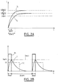
- Figure 2A is a graphical representation of the current flowing a transmitting coil when a constant voltage is applied to it.
- Figure 2B is a graphical representation of the current flowing through the emitting coil for a first value of the supply voltage of the circuit according to the invention.
- Figure 2C is a graphical representation of the current flowing through the emitting coil for a second value of the supply voltage of the circuit according to the invention.
- Figure 2D is a graph illustrating the possibility of adjusting the intensity reference peak.
- Figure 3 gives an example of modulation of the scope of the diagram emission of the magnetic field.
- FIG. 1 is a schematic representation of a supply circuit AC according to the invention which is connected to a field emitting coil magnetic L.
- This circuit which is connected to a ground includes a first input terminal 1 intended to receive a supply voltage Ubat provided by the vehicle battery and which can vary over time, a second input terminal 2 for receiving a control signal periodic square SC, and a third input terminal 3 for receiving a reference voltage Uref.
- this supply circuit includes a terminal 4 which is intended to apply an output voltage U to the coil L magnetic field transmitter, which is connected on the one hand to this terminal 4 and secondly to ground.
- the reference voltage Uref is a constant voltage corresponding to a peak current of Iref reference desired in the transmitting coil L.
- This supply circuit CA includes a MOS transistor (not shown) which is connected between the first input terminal 1 and output terminal 4, and which is controlled by a control voltage internal to the supply circuit according to the invention. Of this way, the voltage U applied across the emitting coil L is Ubat when the transistor is closed.
- a second curve 12 represents the establishment of the current in the coil for a second constant supply voltage Ubat2.
- this graph shows that the limiting intensity of the current in the coil is Ubat / R, if we apply a constant voltage equal to Ubat across the coil.
- curves 11 and 12 for establishing currents have shapes different, so if we set a reference peak intensity, like for example Iref1, lower than Ubat1 / R and Ubat2 / R, to reach in the coil, the time required to reach this intensity has a different value ⁇ ton1, ⁇ ton2 depending on whether the constant voltage applied to coil terminals is Ubat1 or Ubat2.
- the time for reaching an Iref intensity is all the longer as the Ubat voltage applied is weak.
- Figure 2B shows a graph showing how a signal square command SC having a frequency f is converted by the circuit AC power supply according to the invention at a control voltage Uc for obtain a current I in the emitting coil L, this current in the coil emitter having for frequency f, and for peak intensity the peak intensity of reference Iref1.
- This control voltage Uc controls the open state or closed of the MOS transistor so that it is closed when Uc is non-zero and open otherwise.
- FIG. 2C which is a graph showing the same signals than those of FIG. 2B, for the case where the supply voltage is worth no more Ubat1 but Ubat2, with Ubat2 ⁇ Ubat1, we can see that time ⁇ ton2 necessary for the current in the transmitting coil L to reach the value Iref1 is greater than the time ⁇ ton1 which appears in Figure 2B.
- the supply circuit according to the invention is capable of converting a control signal SC at a current I in the emitting coil L having a peak intensity equal to Iref1 regardless of variations in voltage from the vehicle battery.
- the square control signal SC is converted in a periodic control voltage of rectangular shape Uc having a duty cycle r suitable for the duration ⁇ ton during which the voltage Ubat battery is applied across the emitting coil corresponds to the time required for the current in the coil transmitter reaches the Iref value.
- the time ⁇ ton is established as a function of the supply voltage Ubat, of the resistance R and of the inductance L of the transmitting coil, and finally of the peak current Iref desired in the transmitting coil.
- FIG. 2D which is a graph representing the same signals than those of FIGS. 2B and 2C, for the case where the supply voltage is worth Ubat1 and where the reference current is no longer Iref1 but Iref2, with Iref2 ⁇ Iref1, it can be seen that the supply circuit according to the invention is capable convert a control signal into a current in the emitting coil having a peak intensity equal to Iref2.
- the supply circuit according to the invention interprets the voltage Uref to deduce therefrom the peak current of reference Iref, to deduce the corresponding duty cycle r from it.
- the circuit supply adjusts the duty cycle of the control voltage Uc for that the peak current in the emitting coil has the desired value.
- the supply circuit according to the invention may include, for example a microcontroller to calculate the value ⁇ ton according to the relation (*) or an approximate expression of it, and order for example opening and closing of a MOS transistor connected between the terminal input 1 and output terminal 4.
- the microcontroller can still choose the value of ⁇ ton in a data table it contains. So the MOS transistor will be closed when the control voltage Uc is no zero, during the duration ⁇ ton, so that the current I in the coil L reaches the value of the peak current Iref, then the MOS transistor will be open during the duration ⁇ toff so that the current in the emitting coil decreases until the control voltage Uc is again no nothing.
- an evaluation of the supply voltage Vehicle battery Ubat is performed to calculate the ⁇ ton value and this same value is then used for the duration of an exchange data between the recognition device and the identification unit.
- the value ⁇ ton could be generated by a specialized electronic circuit.
- the form of the signal corresponding to the current in the emitting coil may take the form of a triangular signal having a shape close to that given in FIGS. 2A, 2B, 2C and 2D, taking into account the characteristics specific to electronic components used.
- the emission at the level of the recognition device whose purpose is generally to transmit a bit stream towards an organ identification could for example be performed at frequencies of 125 kHz and 133 kHz.
- the issuance of a 125 kHz signal for 1 ms corresponds to the emission of a bit worth 1
- the emission of a 133 kHz signal for 1 ms corresponds to the emission a bit equal to 0, which allows the identification unit to reconstruct the bit stream emitted by the recognizer by analyzing the signal received.
- the recognition will transmit at 125 kHz for 1 ms, then at 133 kHz for 1 ms, then at 125 kHz for 2 ms.
- Figure 3 which is an illustration of the magnetic field diagram emitted by a transmitting coil comprises a transmitting coil L and emission diagrams D1 and D2 corresponding for example to the intensities reference peaks Iref1 and Iref2.
- the radiation diagram of a magnetic field emitted by a transmitting coil is proportional to the current flowing through the coil. So, the range of the emitted field is therefore proportional to the Iref value of the selected peak reference intensity.
- capacitive phenomena that appear between the emitting coil and the sheet can give rise to the emission of an electric field of the same frequency that the magnetic field emitted, so that the emitted field is then a electromagnetic field.
- the invention is not only reserved for the embodiments described above, and can also be applied to any field in which one wishes supply a transmitting coil to emit a magnetic field according to a diagram which remains stable regardless of voltage fluctuations feed.
Landscapes
- Engineering & Computer Science (AREA)
- Computer Networks & Wireless Communication (AREA)
- Physics & Mathematics (AREA)
- General Physics & Mathematics (AREA)
- Charge And Discharge Circuits For Batteries Or The Like (AREA)
- Control Of Charge By Means Of Generators (AREA)
- Lock And Its Accessories (AREA)
- Selective Calling Equipment (AREA)
Abstract
Description
Claims (3)
- Un circuit électronique destiné à alimenter une bobine émettrice de champ magnétique, ayant une première borne d'entrée (1) pour recevoir une tension d'alimentation (Ubat), une seconde borne d'entrée (2) pour recevoir un signal de commande périodique (SC), une borne de sortie (4) pour appliquer une tension de sortie (U) aux bornes de ladite bobine émettrice (L), de manière à convertir ledit signal de commande périodique en un champ magnétique périodique émis par la bobine, caractérisé en ce que, ladite tension de sortie (U) est un signal périodique ayant une période identique à la période du signal de commande (SC) et un rapport cyclique qui dépend de la tension d'alimentation (Ubat), pour qu'un courant circulant dans la bobine ait une intensité crête correspondant à une intensité crête de référence.
- Un circuit électrique selon la revendication 1 dans lequel l'intensité crête de référence est réglable pour modifier volontairement la portée (D1, D2) du champ magnétique émis.
- Un système dit mains libres destiné à commander le déverrouillage d'ouvrants d'un véhicule et/ou à autoriser le démarrage d'un véhicule comprenant un circuit électronique selon la revendication 1 ou 2, dans lequel la tension d'alimentation est fournie par une batterie du véhicule.
Applications Claiming Priority (2)
| Application Number | Priority Date | Filing Date | Title |
|---|---|---|---|
| FR0005043A FR2808137B1 (fr) | 2000-04-19 | 2000-04-19 | Pilote d'antenne a courant crete constant |
| FR0005043 | 2000-04-19 |
Publications (2)
| Publication Number | Publication Date |
|---|---|
| EP1148191A1 true EP1148191A1 (fr) | 2001-10-24 |
| EP1148191B1 EP1148191B1 (fr) | 2005-08-17 |
Family
ID=8849418
Family Applications (1)
| Application Number | Title | Priority Date | Filing Date |
|---|---|---|---|
| EP01400960A Expired - Lifetime EP1148191B1 (fr) | 2000-04-19 | 2001-04-13 | Pilote d'antenne à courant crête constant |
Country Status (5)
| Country | Link |
|---|---|
| US (1) | US6420837B2 (fr) |
| EP (1) | EP1148191B1 (fr) |
| DE (1) | DE60112645T2 (fr) |
| ES (1) | ES2247032T3 (fr) |
| FR (1) | FR2808137B1 (fr) |
Cited By (1)
| Publication number | Priority date | Publication date | Assignee | Title |
|---|---|---|---|---|
| WO2004097748A1 (fr) * | 2003-04-25 | 2004-11-11 | Conti Temic Microelectronic Gmbh | Procede pour actionner un dispositif emetteur et dispositif emetteur fonctionnant selon ledit procede |
Families Citing this family (1)
| Publication number | Priority date | Publication date | Assignee | Title |
|---|---|---|---|---|
| FR2808138B1 (fr) * | 2000-04-19 | 2002-06-07 | Valeo Electronique | Pilote d'antenne emetrice de champ magnetique a circuit rlc |
Citations (5)
| Publication number | Priority date | Publication date | Assignee | Title |
|---|---|---|---|---|
| GB2316775A (en) * | 1996-08-30 | 1998-03-04 | Caterpillar Inc | Pulse width modulation driver having peak current control |
| US5831420A (en) * | 1997-04-28 | 1998-11-03 | Motorola, Inc. | Pulse load averaging power converter |
| US5914849A (en) * | 1994-04-26 | 1999-06-22 | Kilovac Corporation | DC actuator control circuit with voltage compensation, current control and fast dropout period |
| US5969515A (en) * | 1998-02-27 | 1999-10-19 | Motorola, Inc. | Apparatus and method for digital control of a power converter current |
| US6016260A (en) * | 1997-12-10 | 2000-01-18 | U.S. Philips Corporation | Switched-mode power supply with current and voltage limitation |
Family Cites Families (1)
| Publication number | Priority date | Publication date | Assignee | Title |
|---|---|---|---|---|
| US6167094A (en) * | 1996-10-15 | 2000-12-26 | Siemens Aktiengesellschaft | Data transmission circuit having a station and a response circuit |
-
2000
- 2000-04-19 FR FR0005043A patent/FR2808137B1/fr not_active Expired - Lifetime
-
2001
- 2001-04-13 DE DE60112645T patent/DE60112645T2/de not_active Expired - Lifetime
- 2001-04-13 ES ES01400960T patent/ES2247032T3/es not_active Expired - Lifetime
- 2001-04-13 EP EP01400960A patent/EP1148191B1/fr not_active Expired - Lifetime
- 2001-04-18 US US09/836,389 patent/US6420837B2/en not_active Expired - Lifetime
Patent Citations (5)
| Publication number | Priority date | Publication date | Assignee | Title |
|---|---|---|---|---|
| US5914849A (en) * | 1994-04-26 | 1999-06-22 | Kilovac Corporation | DC actuator control circuit with voltage compensation, current control and fast dropout period |
| GB2316775A (en) * | 1996-08-30 | 1998-03-04 | Caterpillar Inc | Pulse width modulation driver having peak current control |
| US5831420A (en) * | 1997-04-28 | 1998-11-03 | Motorola, Inc. | Pulse load averaging power converter |
| US6016260A (en) * | 1997-12-10 | 2000-01-18 | U.S. Philips Corporation | Switched-mode power supply with current and voltage limitation |
| US5969515A (en) * | 1998-02-27 | 1999-10-19 | Motorola, Inc. | Apparatus and method for digital control of a power converter current |
Cited By (1)
| Publication number | Priority date | Publication date | Assignee | Title |
|---|---|---|---|---|
| WO2004097748A1 (fr) * | 2003-04-25 | 2004-11-11 | Conti Temic Microelectronic Gmbh | Procede pour actionner un dispositif emetteur et dispositif emetteur fonctionnant selon ledit procede |
Also Published As
| Publication number | Publication date |
|---|---|
| US6420837B2 (en) | 2002-07-16 |
| DE60112645T2 (de) | 2006-06-08 |
| US20020003500A1 (en) | 2002-01-10 |
| FR2808137B1 (fr) | 2002-06-07 |
| FR2808137A1 (fr) | 2001-10-26 |
| EP1148191B1 (fr) | 2005-08-17 |
| ES2247032T3 (es) | 2006-03-01 |
| DE60112645D1 (de) | 2005-09-22 |
Similar Documents
| Publication | Publication Date | Title |
|---|---|---|
| EP1312032A1 (fr) | Lecteur a haute sensibilite pour transpondeurs passifs | |
| EP1148192B1 (fr) | Pilote d'antenne émettrice de champ magnétique à circuit RLC | |
| EP0762147B1 (fr) | Détecteur de proximité inductif universel | |
| FR2804557A1 (fr) | Adaptation de la puissance d'emission d'un lecteur de transpondeur electromagnetique | |
| FR2680585A1 (fr) | Circuit generateur de tension interne correspondant a une tension externe appliquee a une puce a semi-conducteur. | |
| EP1148191B1 (fr) | Pilote d'antenne à courant crête constant | |
| WO1994018520A1 (fr) | Dispositif de deminage | |
| EP1087332A1 (fr) | Transpondeur destiné à plusieurs applications différentes | |
| EP0010010B1 (fr) | Dispositif à seuil permettant de distinguer le blanc du noir sur un document et émetteur de télécopie comportant un tel dispositif | |
| EP1071213A1 (fr) | Commande d'un transistor MOS de puissance | |
| FR2776781A1 (fr) | Dispositif de controle de l'impedance ramenee sur l'antenne d'une etiquette electromagnetique | |
| CN110979215B (zh) | 车辆用部件 | |
| FR2752651A1 (fr) | Circuit pour realiser une oscillation modulee en amplitude | |
| EP0891597B1 (fr) | Objet electronique portatif pour l'echange d'informations a distance | |
| FR2813149A1 (fr) | Antenne de generation d'un champ electromagnetique pour transpondeur | |
| FR2814130A1 (fr) | Vehicule automobile comprenant un pilote d'antenne emettrice de champ electronique alimente par un elevateur de tension | |
| FR3098908A1 (fr) | Capteur sans contact pour véhicule automobile | |
| FR2654880A1 (fr) | Circuit integre de puissance "intelligent" du type mos, pour la commande de l'alimentation d'une charge electrique. | |
| EP3296759B1 (fr) | Emetteur radar muni d'au moins un tube hyperfréquence | |
| EP1739818A1 (fr) | Procédé de régulation du courant de charge d'une source d'énergie d'un objet portable couplé inductivement à un dispositif chargeur, et dispositif chargeur pour sa mise en oeuvre | |
| EP0851563A1 (fr) | dispositif d'alimentation à découpage régulée en pertubations électromagnétiques | |
| EP1039408A1 (fr) | Telealimentation d'un transpondeur électromagnétique | |
| FR2890255A1 (fr) | Dispositif de commande de tension de sortie pour un alternateur de vehicule | |
| FR2706698A1 (fr) | Dispositif électronique pour l'adaptation de la tension efficace d'alimentation aux bornes d'une charge résistive. | |
| EP1739817A1 (fr) | Dispositif chargeur pour la transmission d'énergie électrique avec un objet portable |
Legal Events
| Date | Code | Title | Description |
|---|---|---|---|
| PUAI | Public reference made under article 153(3) epc to a published international application that has entered the european phase |
Free format text: ORIGINAL CODE: 0009012 |
|
| AK | Designated contracting states |
Kind code of ref document: A1 Designated state(s): DE ES FR GB IT Kind code of ref document: A1 Designated state(s): AT BE CH CY DE DK ES FI FR GB GR IE IT LI LU MC NL PT SE TR |
|
| AX | Request for extension of the european patent |
Free format text: AL;LT;LV;MK;RO;SI |
|
| 17P | Request for examination filed |
Effective date: 20020424 |
|
| AKX | Designation fees paid |
Free format text: DE ES FR GB IT |
|
| RAP1 | Party data changed (applicant data changed or rights of an application transferred) |
Owner name: VALEO SECURITE HABITACLE |
|
| RAP1 | Party data changed (applicant data changed or rights of an application transferred) |
Owner name: VALEO SECURITE HABITACLE S.A.S. |
|
| GRAP | Despatch of communication of intention to grant a patent |
Free format text: ORIGINAL CODE: EPIDOSNIGR1 |
|
| GRAS | Grant fee paid |
Free format text: ORIGINAL CODE: EPIDOSNIGR3 |
|
| GRAA | (expected) grant |
Free format text: ORIGINAL CODE: 0009210 |
|
| AK | Designated contracting states |
Kind code of ref document: B1 Designated state(s): DE ES FR GB IT |
|
| REG | Reference to a national code |
Ref country code: GB Ref legal event code: FG4D Free format text: NOT ENGLISH |
|
| REF | Corresponds to: |
Ref document number: 60112645 Country of ref document: DE Date of ref document: 20050922 Kind code of ref document: P |
|
| GBT | Gb: translation of ep patent filed (gb section 77(6)(a)/1977) |
Effective date: 20051109 |
|
| REG | Reference to a national code |
Ref country code: ES Ref legal event code: FG2A Ref document number: 2247032 Country of ref document: ES Kind code of ref document: T3 |
|
| PLBE | No opposition filed within time limit |
Free format text: ORIGINAL CODE: 0009261 |
|
| STAA | Information on the status of an ep patent application or granted ep patent |
Free format text: STATUS: NO OPPOSITION FILED WITHIN TIME LIMIT |
|
| 26N | No opposition filed |
Effective date: 20060518 |
|
| REG | Reference to a national code |
Ref country code: FR Ref legal event code: PLFP Year of fee payment: 16 |
|
| REG | Reference to a national code |
Ref country code: FR Ref legal event code: PLFP Year of fee payment: 17 |
|
| PGFP | Annual fee paid to national office [announced via postgrant information from national office to epo] |
Ref country code: ES Payment date: 20170508 Year of fee payment: 17 Ref country code: IT Payment date: 20170411 Year of fee payment: 17 |
|
| REG | Reference to a national code |
Ref country code: FR Ref legal event code: PLFP Year of fee payment: 18 |
|
| PG25 | Lapsed in a contracting state [announced via postgrant information from national office to epo] |
Ref country code: IT Free format text: LAPSE BECAUSE OF NON-PAYMENT OF DUE FEES Effective date: 20180413 |
|
| REG | Reference to a national code |
Ref country code: ES Ref legal event code: FD2A Effective date: 20190912 |
|
| PG25 | Lapsed in a contracting state [announced via postgrant information from national office to epo] |
Ref country code: ES Free format text: LAPSE BECAUSE OF NON-PAYMENT OF DUE FEES Effective date: 20180414 |
|
| PGFP | Annual fee paid to national office [announced via postgrant information from national office to epo] |
Ref country code: DE Payment date: 20200408 Year of fee payment: 20 Ref country code: FR Payment date: 20200430 Year of fee payment: 20 |
|
| PGFP | Annual fee paid to national office [announced via postgrant information from national office to epo] |
Ref country code: GB Payment date: 20200427 Year of fee payment: 20 |
|
| REG | Reference to a national code |
Ref country code: DE Ref legal event code: R071 Ref document number: 60112645 Country of ref document: DE |
|
| REG | Reference to a national code |
Ref country code: GB Ref legal event code: PE20 Expiry date: 20210412 |
|
| PG25 | Lapsed in a contracting state [announced via postgrant information from national office to epo] |
Ref country code: GB Free format text: LAPSE BECAUSE OF EXPIRATION OF PROTECTION Effective date: 20210412 |