EP1147883A2 - Calender rollers and method for producing laminated sheet - Google Patents
Calender rollers and method for producing laminated sheet Download PDFInfo
- Publication number
- EP1147883A2 EP1147883A2 EP01109038A EP01109038A EP1147883A2 EP 1147883 A2 EP1147883 A2 EP 1147883A2 EP 01109038 A EP01109038 A EP 01109038A EP 01109038 A EP01109038 A EP 01109038A EP 1147883 A2 EP1147883 A2 EP 1147883A2
- Authority
- EP
- European Patent Office
- Prior art keywords
- plastic material
- sheet
- material sheet
- roller
- laminated
- Prior art date
- Legal status (The legal status is an assumption and is not a legal conclusion. Google has not performed a legal analysis and makes no representation as to the accuracy of the status listed.)
- Withdrawn
Links
Images

Classifications
-
- B—PERFORMING OPERATIONS; TRANSPORTING
- B32—LAYERED PRODUCTS
- B32B—LAYERED PRODUCTS, i.e. PRODUCTS BUILT-UP OF STRATA OF FLAT OR NON-FLAT, e.g. CELLULAR OR HONEYCOMB, FORM
- B32B38/00—Ancillary operations in connection with laminating processes
-
- B—PERFORMING OPERATIONS; TRANSPORTING
- B29—WORKING OF PLASTICS; WORKING OF SUBSTANCES IN A PLASTIC STATE IN GENERAL
- B29C—SHAPING OR JOINING OF PLASTICS; SHAPING OF MATERIAL IN A PLASTIC STATE, NOT OTHERWISE PROVIDED FOR; AFTER-TREATMENT OF THE SHAPED PRODUCTS, e.g. REPAIRING
- B29C43/00—Compression moulding, i.e. applying external pressure to flow the moulding material; Apparatus therefor
- B29C43/22—Compression moulding, i.e. applying external pressure to flow the moulding material; Apparatus therefor of articles of indefinite length
- B29C43/24—Calendering
-
- B—PERFORMING OPERATIONS; TRANSPORTING
- B29—WORKING OF PLASTICS; WORKING OF SUBSTANCES IN A PLASTIC STATE IN GENERAL
- B29C—SHAPING OR JOINING OF PLASTICS; SHAPING OF MATERIAL IN A PLASTIC STATE, NOT OTHERWISE PROVIDED FOR; AFTER-TREATMENT OF THE SHAPED PRODUCTS, e.g. REPAIRING
- B29C43/00—Compression moulding, i.e. applying external pressure to flow the moulding material; Apparatus therefor
- B29C43/22—Compression moulding, i.e. applying external pressure to flow the moulding material; Apparatus therefor of articles of indefinite length
- B29C43/28—Compression moulding, i.e. applying external pressure to flow the moulding material; Apparatus therefor of articles of indefinite length incorporating preformed parts or layers, e.g. compression moulding around inserts or for coating articles
-
- B—PERFORMING OPERATIONS; TRANSPORTING
- B29—WORKING OF PLASTICS; WORKING OF SUBSTANCES IN A PLASTIC STATE IN GENERAL
- B29C—SHAPING OR JOINING OF PLASTICS; SHAPING OF MATERIAL IN A PLASTIC STATE, NOT OTHERWISE PROVIDED FOR; AFTER-TREATMENT OF THE SHAPED PRODUCTS, e.g. REPAIRING
- B29C43/00—Compression moulding, i.e. applying external pressure to flow the moulding material; Apparatus therefor
- B29C43/22—Compression moulding, i.e. applying external pressure to flow the moulding material; Apparatus therefor of articles of indefinite length
- B29C43/30—Making multilayered or multicoloured articles
- B29C43/305—Making multilayered articles
-
- B—PERFORMING OPERATIONS; TRANSPORTING
- B32—LAYERED PRODUCTS
- B32B—LAYERED PRODUCTS, i.e. PRODUCTS BUILT-UP OF STRATA OF FLAT OR NON-FLAT, e.g. CELLULAR OR HONEYCOMB, FORM
- B32B2307/00—Properties of the layers or laminate
- B32B2307/40—Properties of the layers or laminate having particular optical properties
- B32B2307/412—Transparent
-
- B—PERFORMING OPERATIONS; TRANSPORTING
- B32—LAYERED PRODUCTS
- B32B—LAYERED PRODUCTS, i.e. PRODUCTS BUILT-UP OF STRATA OF FLAT OR NON-FLAT, e.g. CELLULAR OR HONEYCOMB, FORM
- B32B2307/00—Properties of the layers or laminate
- B32B2307/50—Properties of the layers or laminate having particular mechanical properties
- B32B2307/538—Roughness
-
- B—PERFORMING OPERATIONS; TRANSPORTING
- B32—LAYERED PRODUCTS
- B32B—LAYERED PRODUCTS, i.e. PRODUCTS BUILT-UP OF STRATA OF FLAT OR NON-FLAT, e.g. CELLULAR OR HONEYCOMB, FORM
- B32B37/00—Methods or apparatus for laminating, e.g. by curing or by ultrasonic bonding
- B32B37/14—Methods or apparatus for laminating, e.g. by curing or by ultrasonic bonding characterised by the properties of the layers
- B32B37/15—Methods or apparatus for laminating, e.g. by curing or by ultrasonic bonding characterised by the properties of the layers with at least one layer being manufactured and immediately laminated before reaching its stable state, e.g. in which a layer is extruded and laminated while in semi-molten state
- B32B37/156—Methods or apparatus for laminating, e.g. by curing or by ultrasonic bonding characterised by the properties of the layers with at least one layer being manufactured and immediately laminated before reaching its stable state, e.g. in which a layer is extruded and laminated while in semi-molten state at least one layer is calendered and immediately laminated
-
- Y—GENERAL TAGGING OF NEW TECHNOLOGICAL DEVELOPMENTS; GENERAL TAGGING OF CROSS-SECTIONAL TECHNOLOGIES SPANNING OVER SEVERAL SECTIONS OF THE IPC; TECHNICAL SUBJECTS COVERED BY FORMER USPC CROSS-REFERENCE ART COLLECTIONS [XRACs] AND DIGESTS
- Y10—TECHNICAL SUBJECTS COVERED BY FORMER USPC
- Y10T—TECHNICAL SUBJECTS COVERED BY FORMER US CLASSIFICATION
- Y10T156/00—Adhesive bonding and miscellaneous chemical manufacture
- Y10T156/11—Methods of delaminating, per se; i.e., separating at bonding face
- Y10T156/1168—Gripping and pulling work apart during delaminating
- Y10T156/1189—Gripping and pulling work apart during delaminating with shearing during delaminating
-
- Y—GENERAL TAGGING OF NEW TECHNOLOGICAL DEVELOPMENTS; GENERAL TAGGING OF CROSS-SECTIONAL TECHNOLOGIES SPANNING OVER SEVERAL SECTIONS OF THE IPC; TECHNICAL SUBJECTS COVERED BY FORMER USPC CROSS-REFERENCE ART COLLECTIONS [XRACs] AND DIGESTS
- Y10—TECHNICAL SUBJECTS COVERED BY FORMER USPC
- Y10T—TECHNICAL SUBJECTS COVERED BY FORMER US CLASSIFICATION
- Y10T156/00—Adhesive bonding and miscellaneous chemical manufacture
- Y10T156/19—Delaminating means
- Y10T156/1961—Severing delaminating means [e.g., chisel, etc.]
- Y10T156/1967—Cutting delaminating means
- Y10T156/1972—Shearing delaminating means
Definitions
- the present invention relates to a laminated sheet provided with improved precision in surface roughness. More particularly, the present invention relates to a set of calender rollers that are suitable for producing a pressure-sensitive adhesive sheet and to a method for producing a laminated sheet employing the set of calender rollers.
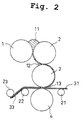
- Fig. 2 is a view illustrating the structure of a set of conventional calender rollers and a method for producing a laminated sheet of a plastic material sheet and base material sheet using the set of calender rollers, taking the set of four inverted-L calender rollers as an example.
- a plastic material or a coating liquid loaded between a side roller 1 and a top roller 2 forms a first bank 11, and is then rolled with the side roller 1 and the top roller 2 to pass over the top roller 2. Then, the plastic material is further rolled in between the top roller 2 and a center roller 3 to form into a second bank 12 between these rollers at this time. After the plastic material has been rolled between the top roller 2 and the center roller 3, the plastic material sheet passing over the center roller 3 forms a third bank 13 between the center roller 3 and a bottom roller 4.
- the base material sheet 31 is dispensed from a dispenser roller 21 to pass through between the center roller 3 and the bottom roller 4.
- the plastic material is applied and laminated on the base material sheet 31 to form into a laminated sheet 33 at the third bank and at the nip portion between the center roller 3 and the bottom roller 4.
- the laminated sheet 33 is wound around roller 23 in a manner such that the non-laminated surface of the plastic material sheet is in contact with the rear surface of the base material sheet 31.
- the base material sheet 31 passes through the nip between the center roller 3 and bottom roller 4 to form into a laminated sheet, and thereafter the laminated sheet 33 is released from the center roller 3 with the winding roller 22.
- the layer of the plastic material is not only strongly adhered to and laminated on the base material sheet 31 but also stuck on the center roller 3. For this reason, the surface of the plastic material layer is released between the center roller 3 and the laminated sheet 33 , so that the surface of the plastic material layer of the laminated sheet 33 becomes uneven with greater projections and depressions.
- the plastic material layer gradually become identical in roughness of the surface to the surface of the base material sheet, but will never become the same as the base material sheet, allowing the projections and depressions to remain to some extent.
- the object of the invention is to provide a laminated sheet having a surface with less projections and depressions, and thus with reduced roughness and improved smoothness.
- Another object of the present invention is to provide a set of calender rollers suitable for producing a pressure-sensitive adhesive sheet.
- Still another object is to provide a method for producing a laminated sheet employing the set of calender rollers.
- the laminated sheet formed after having passed through the nip portion remains held on the holding roller due to the tackiness between the plastic material sheet and the holding roller. Then, the laminated sheet is released from the calender rollers by the releasing effect of the release member without projections and depressions being produced on the surface thereof, thus forming into a laminated sheet having a very smooth surface.
- the release member prevents the plastic material stuck to the holding roller from being elongated due to the tackiness, when released from the holding roller, to generate no residual strain along therewith.
- a hot air blower for supplying heated air, a small diameter roller, or a scraper. More particularly, a doctor knife is preferably employed in the set of calender rollers according to the present invention.
- a release member may be used in contact with or being spaced apart from the holding roller. It is preferable to install the small diameter roller or the like being spaced a little apart from the holding roller, whereas the doctor knife or the like is preferably installed in contact with the holding roller. The doctor knife releases the plastic material sheet from the surface of the holding roller as if scraping from the sheet.
- the aforementioned set of calender rollers is preferably adapted such that the release member can be heated.
- the temperature for heating the release member is determined to be appropriate according to the type thereof or the type of the plastic material to be used, however, preferably 50 to 250°C.
- the doctor knife is preferably heated at 100 to 200°C.
- Heating the release member will make the surface of the plasticmaterial sheet of the resulting laminated sheet smoother .
- the doctor knife is preferably vibrated at a frequency of 0.01Hz to 30kHz. It is more preferable that the frequency ranges from 0.1 to 1Hz or 20kHz to 30kHz for providing ultrasonic vibration.
- the vibration may be produced in the direction of length and/or width of the doctor knife .
- the amplitude may preferably range from 2 to 20mm for vibration at a frequency of 0.1 to 1Hz and from 1 to 5 ⁇ m for vibration at a frequency of 20kHz to 30kHz.
- a vibration means a known vibration loading means is available. For example, an air cylinder or the like is preferably used for vibration at a frequency of 0.1 to 1Hz, while an ultrasonic vibrator is more preferably used for vibration at a frequency of 20kHz to 30kHz.
- the present invention also provides a method for producing a laminated sheet by laminating a plastic material sheet on a base material sheet using a set of calender rollers .
- the method is characterized in that the set of calender rollers comprises at least three rollers, a nip portion is formed with a pair of nip rollers including a holding roller for holding a rolled plastic material sheet.
- a release member is arranged in proximity to or in contact with the holding roller.
- the method is also characterized in that a plastic material is rolled into the plastic material sheet, then the plastic material sheet is laminated onto a base material sheet at the nip portion. Thereafter, a plastic material sheet layer of the laminated sheet is released from the holding roller with the release member.
- a doctor knife is used as the release member and preferably vibrated.
- the plastic material sheet and the base material sheet are laminated onto each other at the nip portion. Thereafter, the releasing effect of the release member allows the laminated sheet to be released from the calender rollers without causing any projections and depressions on the surface thereof. Thus, a laminated sheet with a smoother surface is produced.
- the release member is preferably heated at 50°C or more.
- the plastic material employed by the present invention has tackiness in the laminating process using the calender rollers. It is out of the question whether the plastic material still has tackiness after having been laminated or cooled down. Nevertheless, it is preferable that the plastic material is a pressure-sensitive adhesive and the laminated sheet is a pressure-sensitive adhesive sheet.
- the pressure-sensitive adhesive used for the pressure-sensitive adhesive sheet can be used without limitation so long as it can be calendered, but is preferably a rubber-based pressure-sensitive adhesive.
- the rubber-based pressure-sensitive adhesive is best calendered.
- the rubber-based pressure-sensitive adhesive has strong tackiness and therefore can easily make the tackiness surface thereof rougher when released from the calendar rollers. Accordingly, the present invention can provide a pressure-sensitive adhesive sheet with a smoother tackiness surface.
- Fig. 1 is a view illustrating a preferred embodiment of a set of calender rollers according to the present invention.
- the example shown in the figure is a set of four inverted-L calender rollers with a doctor knife being employed as a release member.
- the set of four inverted-L calender rollers C comprises the side roller 1, the top roller 2, the center roller 3, and the bottom roller 4 to hold a sheeted plastic material M around the center roller 3.
- the center roller 3 serves as a holding roller.
- the center roller 3 and the bottom roller 4 constitute nip rollers having a nip portion P.
- a doctor knife 41 in proximity to or in contact with the center roller 3.
- the doctor knife 41 is usually installed in contact with the holding roller 3.
- the doctor knife 41 is made of a known material used for coating, for example, a material including metal such as iron and stainless steel or hard resin . When iron is used, the doctor knife 41 is preferably coated with a protective layer such as by hard chromium plating.
- a plastic material loaded between the side roller 1 and the top roller 2 forms the first bank 11, and is then rolled to pass over the top roller 2. Then, the sheeted plastic material is further rolled in between the top roller 2 and the center roller 3 and forms the second bank 12 therebetween at this time.
- the plastic material sheet M which has been thus rolled in between the top roller 2 and the center roller 3 and stuck to and held on the center roller 3, is wound by in the form of a sheet and thus held on the center roller 3 or a holding roller, and then fed to the nip portion P.
- the base material sheet 31 is rewound off a source sheet (not shown) to be dispensed from the dispenser roller 21. Then, the base material sheet 31 is fed to the nip portion P to be pressed and laminated onto the plastic material sheet M to form into the laminated sheet 33.
- the pressed laminated sheet 33 is transported while attached to the center roller 3 by the tackiness between the surface of the plastic material sheet and the center roller 3. Then, behind the nip portion P, the laminated sheet 33 is released with the doctor knife 41 installed in front of the second bank 12, while being subjected to a releasing force provided by the non-tacky roller 22 or the like. Then, the laminated sheet 33 passes over the non-tacky roller 22 to be wound around the laminated-sheet winding roller 23.
- This example shows a set of four inverted-L calender rollers provided with the doctor knife 41 as an example of a release member.
- the identical release member can be applied to known calender rollers such as a set of three inverted-L calender rollers , a set of three to four Z-shaped calender rollers , a set of six calender rollers.
- the preferred low tackiness treatment includes poly-fluorinated ethylene coating, and nickel/poly-fluorinated ethylene coating and plating.
- the doctor knife can be heated, for example, with an electric heater provided inside the doctor knife or by means of a heating medium passing through a heating medium circulating path.
- the crude rubber used for rubber-based pressure-sensitive adhesive
- any type of rubber can be employed as pressure-sensitive adhesive without limitation.
- the crude rubber includes natural rubber and synthetic rubber such as polyisoprene rubber, polybutadiene rubber, styrene-butadiene rubber, butyl rubber, and ethylene-propylene rubber.
- natural rubber provides strong tackiness and thus is most preferably used.
- additives are selected as appropriate according to their application and include inorganic materials such as silica, alumina, titanium oxide, and calcium carbonate; colorant such as pigment; antioxidants; and tackifiers.
- the base material sheet includes paper such as kraft paper; thermoplastic resin film such as polyethylene terephthalate (PET) film, oriented polypropylene (OPP) film, polyamide film, and polyaramide film; and non-woven fabric.
- PET polyethylene terephthalate
- OPP oriented polypropylene
- An amount of natural rubber was subjected to mastication with a mixing roller to provide masticated rubber having a Mooney viscosity ML 1+4 (100°C) of 60.
- 1500g of rubber was put into a 5-liter pressure kneader heated at 120°C.
- 750g of calcium carbonate power and 30g of phenolic antioxidant were put into the kneader at the same time and mixed with one another for five minutes.
- 1350g of petroleum resin tackifier was also added and mixed for 20 minutes. Subsequently, the mixture was taken out of the kneader to obtain a pressure-sensitive adhesive composition.
- the mixture was inputted into a set of four inverted-L calender rollers (each roller having a diameter of 254mm) to pass through the pass line shown in Fig. 1 and was thus subjected to coating and lamination at a line speed of 5m/min.
- An OPP sheet of thickness 50 ⁇ m was employed as the base material sheet 31.
- a laminated sheet was prepared in the same manner as in Example 1 except that the doctor knife was provided with a band heater and a temperature sensor and heated at 150°C.
- a laminated sheet was prepared in the same manner as in Example 1 except that the doctor knife was provided with an air cylinder so as to be vibrated in the direction of the width of the sheet and was vibrated to be used at a frequency of 0.5Hz.
- Coating was applied to a sheet at a line speed of 5m/min in the same manner as Example 1 except that the conventional pass line shown in Fig. 2 was used.
- a doctor knife is provided to release a plastic material sheet in such a manner that the surface of a plastic material sheet of the laminated sheet is scraped from the holding roller. This makes it possible to reduce the roughness of the plastic material layer, thereby providing the laminated sheet with an improved outer appearance and improved product properties.
- the doctor knife was heated and found effective at improving surface smoothness.
Landscapes
- Engineering & Computer Science (AREA)
- Mechanical Engineering (AREA)
- Casting Or Compression Moulding Of Plastics Or The Like (AREA)
- Laminated Bodies (AREA)
- Coating Apparatus (AREA)
- Application Of Or Painting With Fluid Materials (AREA)
- Moulds For Moulding Plastics Or The Like (AREA)
Abstract
the nip portion (P) is formed with a pair of nip rollers including a holding roller (3) for holding the rolled plastic material sheet (M), and behind the nip portion, a release member (41) for releasing the laminated plastic material sheet from the holding roller (3) is arranged in proximity to or in contact with the holding roller.
Description
the set of calender rollers comprises at least three rollers , a nip portion is formed with a pair of nip rollers including a holding roller for holding a rolled plastic material sheet, and behind the nip portion, a release member is arranged in proximity to or in contact with the holding roller, and
a plastic material is rolled into the plastic material sheet, then the plastic material sheet is laminated onto a base material sheet at the nip portion, and thereafter a plastic material sheet layer of the laminated sheet is released from the holding roller with the release member.
- C
- Four inverted-L calender rollers
- M
- Plastic material sheet
- 31
- Base material sheet
- 33
- Laminated sheet
- 41
- Doctor knife
| Average roughness (Ra) | Average height (RMS) | |
| EXAMPLE 1 | 0.243 | 0.588 |
| EXAMPLE 2 | 0.201 | 0.523 |
| EXAMPLE 3 | 0.225 | 0.541 |
| COMPARATIVE EXAMPLE 1 | 12.71 | 20.35 |
Claims (10)
- A set of calender rollers comprising at least three rollers , for rolling a plastic material into a plastic material sheet and for laminating said plastic material sheet onto a base material sheet at a nip portion to be formed into a laminated plastic material sheet, wherein
said nip portion is formed with a pair of nip rollers including a holding roller for holding said rolled plastic material sheet, and behind said nip portion, a release member for releasing said laminated plastic material sheet from said holding roller is arranged in proximity to or in contact with said holding roller. - The set of calender rollers according to Claim 1, wherein said release member is able to be heated.
- The set of calender rollers according to Claim 1, wherein said release member is a doctor knife.
- The set of calender rollers according to Claim 3, wherein said doctor knife is able to be vibrated.
- A method for producing a laminated sheet by laminating a plastic material sheet on a base material sheet using a set of calender rollers, wherein
said set of calender rollers comprises at least three rollers, a nip portion is formed with a pair of nip rollers including a holding roller for holding a rolled plastic material sheet, and behind said nip portion, a release member is arranged in proximity to or in contact with said holding roller, and
a plastic material is rolled into said plastic material sheet, then said plastic material sheet is laminated onto a base material sheet at said nip portion, and thereafter a plastic material sheet layer of said laminated sheet is released from said holding roller with said release member. - The method for producing a laminated sheet according to Claim 5, wherein said release member is heated at 50°C or more.
- The method for producing a laminated sheet according to Claim 5, wherein said release member is a doctor knife.
- The method for producing a laminated sheet according to Claim 7, wherein said doctor knife is vibrated.
- The method for producing a laminated sheet according to any one of Claims 5, wherein said plastic material is a pressure-sensitive adhesive and said laminated sheet is a pressure-sensitive adhesive sheet.
- The method for producing a laminated sheet according to Claim 9, wherein said pressure-sensitive adhesive is a rubber-based pressure-sensitive adhesive.
Applications Claiming Priority (4)
| Application Number | Priority Date | Filing Date | Title |
|---|---|---|---|
| JP2000120322 | 2000-04-21 | ||
| JP2000120322 | 2000-04-21 | ||
| JP2000314629 | 2000-10-16 | ||
| JP2000314629A JP4393691B2 (en) | 2000-04-21 | 2000-10-16 | CALENDAR ROLL AND METHOD FOR PRODUCING LAMINATED SHEET |
Publications (2)
| Publication Number | Publication Date |
|---|---|
| EP1147883A2 true EP1147883A2 (en) | 2001-10-24 |
| EP1147883A3 EP1147883A3 (en) | 2003-11-19 |
Family
ID=26590515
Family Applications (1)
| Application Number | Title | Priority Date | Filing Date |
|---|---|---|---|
| EP01109038A Withdrawn EP1147883A3 (en) | 2000-04-21 | 2001-04-11 | Calender rollers and method for producing laminated sheet |
Country Status (5)
| Country | Link |
|---|---|
| US (1) | US20010042452A1 (en) |
| EP (1) | EP1147883A3 (en) |
| JP (1) | JP4393691B2 (en) |
| CN (1) | CN1200801C (en) |
| TW (1) | TWM248802U (en) |
Families Citing this family (11)
| Publication number | Priority date | Publication date | Assignee | Title |
|---|---|---|---|---|
| JP4724561B2 (en) * | 2005-01-18 | 2011-07-13 | 株式会社川上鉄工所 | Coating device |
| FI123889B (en) * | 2010-02-26 | 2013-12-13 | Raute Oyj | Method and apparatus for improving the quality characteristics of veneers |
| US9028241B2 (en) | 2012-07-31 | 2015-05-12 | Michelin Recherche Et Technique S.A. | Stripper roll for use with calendering drives processing elastomeric mixes |
| US9073247B2 (en) | 2012-07-31 | 2015-07-07 | Michelin Recherche Et Technique S.A. | Biasing wedge for use with calendering drives processing elastomeric mixes |
| CN103481520A (en) * | 2013-09-23 | 2014-01-01 | 浙江尊华橡塑工业有限公司 | One-time extrusion composite forming machine for double-layer band |
| CN104148235A (en) * | 2014-07-16 | 2014-11-19 | 南京林业大学 | Glue-saving roller glue coating system |
| CN104439918B (en) * | 2014-10-23 | 2017-02-15 | 宜昌船舶柴油机有限公司 | Rolling machining method of sealing tooth section of exhaust connecting pipe |
| US20160221275A1 (en) * | 2015-01-29 | 2016-08-04 | Rohr, Inc. | Method of manufacturing a polyimide film |
| CN105034229A (en) * | 2015-07-08 | 2015-11-11 | 杭州朝阳橡胶有限公司 | Scraper device of lower roller of rubber refining extrusion sheet pressing machine |
| CN110936538A (en) * | 2019-11-05 | 2020-03-31 | 武汉市新洲三角塑料制品有限公司 | A prick turbine for production of PVC film |
| CN112536959A (en) * | 2020-07-20 | 2021-03-23 | 广东欧文莱陶瓷有限公司 | Automatic compounding rolling press device |
Family Cites Families (6)
| Publication number | Priority date | Publication date | Assignee | Title |
|---|---|---|---|---|
| US2375812A (en) * | 1941-10-03 | 1945-05-15 | American Can Co | Coating machine |
| DE1546543A1 (en) * | 1964-02-05 | 1970-10-08 | Gen Tire & Rubber Co | Process for the production of openwork patterns in plastic sheets |
| US3783072A (en) * | 1971-11-02 | 1974-01-01 | Johnson & Johnson | Extrusion process for pressure-sensitive adhesive sheets and tapes |
| US4253902A (en) * | 1980-06-24 | 1981-03-03 | Sansei Seiki Co., Ltd. | Automatic labeler |
| JPS58116101A (en) * | 1981-12-30 | 1983-07-11 | 株式会社 名南製作所 | How to make plywood |
| DE19806609A1 (en) * | 1998-02-18 | 1999-08-19 | Beiersdorf Ag | Process for the continuous, solvent and mastication free production of non-thermoplastic elastomers based self-adhesive compositions |
-
2000
- 2000-10-16 JP JP2000314629A patent/JP4393691B2/en not_active Expired - Lifetime
-
2001
- 2001-04-11 EP EP01109038A patent/EP1147883A3/en not_active Withdrawn
- 2001-04-16 US US09/834,946 patent/US20010042452A1/en not_active Abandoned
- 2001-04-17 TW TW093205903U patent/TWM248802U/en not_active IP Right Cessation
- 2001-04-20 CN CNB011170743A patent/CN1200801C/en not_active Expired - Fee Related
Also Published As
| Publication number | Publication date |
|---|---|
| CN1200801C (en) | 2005-05-11 |
| EP1147883A3 (en) | 2003-11-19 |
| JP2002001750A (en) | 2002-01-08 |
| US20010042452A1 (en) | 2001-11-22 |
| JP4393691B2 (en) | 2010-01-06 |
| TWM248802U (en) | 2004-11-01 |
| CN1320513A (en) | 2001-11-07 |
Similar Documents
| Publication | Publication Date | Title |
|---|---|---|
| JP5833592B2 (en) | Protective film with release surface | |
| US6544639B1 (en) | Adhesive tape strip | |
| KR102043004B1 (en) | Surface protection film fabrication method and fabrication apparatus and surface protection film | |
| US20010042452A1 (en) | Calender rollers and method for producing laminated sheet | |
| MXPA00011916A (en) | Backing for duct tapes. | |
| IL129025A (en) | Pressure-sensitive adhesive construction | |
| CN104312468B (en) | The method for manufacturing strip laminates | |
| US20210402664A1 (en) | Silicone rubber roller for embossing, plastic film production method, a production device using same, and surface protection film | |
| JPS6334830B2 (en) | ||
| JPH07268291A (en) | Method for manufacturing pressure-sensitive adhesive tape roll having transparent appearance even to core | |
| EP0778127B1 (en) | Method for producing a laminated thermoplastic resin film, a laminated thermoplastic resin film and a thermally produced molding of the same | |
| TWI243750B (en) | Masking film for textured surfaces | |
| EP0737731B1 (en) | Separator, packaging material, or pressure-sensitive adhesive tape base material | |
| JPH0762311A (en) | Surface protection film and method for producing the same | |
| EP0798103B1 (en) | Method and apparatus for bonding sheet-like adhesive | |
| US20080286536A1 (en) | Flat Structure That is at Least Partially Provided With a Self-Adhesive Substance | |
| JPH10219208A (en) | Tacky sheet capable of uniformly dispersing air foam | |
| JP2001300964A (en) | Method of manufacturing calender roll and laminated sheet | |
| JP2801132B2 (en) | Manufacturing method of cloth adhesive tape | |
| JPH03101864A (en) | Extrusion laminating method | |
| JP2001300962A (en) | Method of manufacturing calender roll and laminated sheet | |
| JP2001300963A (en) | Method of manufacturing calender roll and laminated sheet | |
| JP2002220570A (en) | Double-sided adhesive tape for fixing rubbing cloth | |
| JPH08282722A (en) | Base material for separators, packaging materials or adhesive tapes | |
| KR200254486Y1 (en) | Adhesive cleaning roll for dust collection |
Legal Events
| Date | Code | Title | Description |
|---|---|---|---|
| PUAI | Public reference made under article 153(3) epc to a published international application that has entered the european phase |
Free format text: ORIGINAL CODE: 0009012 |
|
| AK | Designated contracting states |
Kind code of ref document: A2 Designated state(s): AT BE CH CY DE DK ES FI FR GB GR IE IT LI LU MC NL PT SE TR |
|
| AX | Request for extension of the european patent |
Free format text: AL;LT;LV;MK;RO;SI |
|
| PUAL | Search report despatched |
Free format text: ORIGINAL CODE: 0009013 |
|
| AK | Designated contracting states |
Kind code of ref document: A3 Designated state(s): AT BE CH CY DE DK ES FI FR GB GR IE IT LI LU MC NL PT SE TR |
|
| AX | Request for extension of the european patent |
Extension state: AL LT LV MK RO SI |
|
| STAA | Information on the status of an ep patent application or granted ep patent |
Free format text: STATUS: THE APPLICATION HAS BEEN WITHDRAWN |
|
| 18W | Application withdrawn |
Effective date: 20040129 |