EP1147462B1 - Performance-based control system - Google Patents
Performance-based control system Download PDFInfo
- Publication number
- EP1147462B1 EP1147462B1 EP99967608A EP99967608A EP1147462B1 EP 1147462 B1 EP1147462 B1 EP 1147462B1 EP 99967608 A EP99967608 A EP 99967608A EP 99967608 A EP99967608 A EP 99967608A EP 1147462 B1 EP1147462 B1 EP 1147462B1
- Authority
- EP
- European Patent Office
- Prior art keywords
- fouling
- corrosion
- corrosion rate
- rate
- stream
- Prior art date
- Legal status (The legal status is an assumption and is not a legal conclusion. Google has not performed a legal analysis and makes no representation as to the accuracy of the status listed.)
- Expired - Lifetime
Links
- 238000000034 method Methods 0.000 claims abstract description 80
- 238000012544 monitoring process Methods 0.000 claims abstract description 21
- 238000005260 corrosion Methods 0.000 claims description 177
- 230000007797 corrosion Effects 0.000 claims description 177
- 238000001816 cooling Methods 0.000 claims description 115
- 239000000463 material Substances 0.000 claims description 45
- 230000008859 change Effects 0.000 claims description 36
- 239000003112 inhibitor Substances 0.000 claims description 22
- 230000033116 oxidation-reduction process Effects 0.000 claims description 17
- 230000007423 decrease Effects 0.000 claims description 16
- 230000001590 oxidative effect Effects 0.000 claims description 12
- 239000002270 dispersing agent Substances 0.000 claims description 7
- 229910052736 halogen Inorganic materials 0.000 claims description 6
- 150000002367 halogens Chemical class 0.000 claims description 6
- 238000004519 manufacturing process Methods 0.000 claims description 6
- 230000003247 decreasing effect Effects 0.000 claims description 5
- 239000007800 oxidant agent Substances 0.000 claims description 5
- 230000009471 action Effects 0.000 claims description 4
- 238000013500 data storage Methods 0.000 claims description 2
- XLYOFNOQVPJJNP-UHFFFAOYSA-N water Substances O XLYOFNOQVPJJNP-UHFFFAOYSA-N 0.000 description 88
- 230000004044 response Effects 0.000 description 45
- 239000002826 coolant Substances 0.000 description 42
- 238000004364 calculation method Methods 0.000 description 41
- 239000000126 substance Substances 0.000 description 34
- 230000008569 process Effects 0.000 description 30
- WFIZYGMIIMLKQI-UHFFFAOYSA-M ethyl-methyl-(4,6,11-trioxa-1-aza-5-silabicyclo[3.3.3]undecan-5-ylmethyl)sulfanium;iodide Chemical compound [I-].O1CCN2CCO[Si]1(C[S+](C)CC)OCC2 WFIZYGMIIMLKQI-UHFFFAOYSA-M 0.000 description 26
- 239000000654 additive Substances 0.000 description 21
- 230000000996 additive effect Effects 0.000 description 15
- 239000007788 liquid Substances 0.000 description 14
- 230000000694 effects Effects 0.000 description 13
- 238000001704 evaporation Methods 0.000 description 13
- 238000005259 measurement Methods 0.000 description 13
- 238000009825 accumulation Methods 0.000 description 12
- 230000008020 evaporation Effects 0.000 description 12
- 238000004458 analytical method Methods 0.000 description 10
- 238000013459 approach Methods 0.000 description 10
- 230000001276 controlling effect Effects 0.000 description 9
- 238000001514 detection method Methods 0.000 description 9
- 239000000700 radioactive tracer Substances 0.000 description 9
- 239000000498 cooling water Substances 0.000 description 8
- 239000002253 acid Substances 0.000 description 7
- 238000005516 engineering process Methods 0.000 description 7
- 239000012530 fluid Substances 0.000 description 7
- HEMHJVSKTPXQMS-UHFFFAOYSA-M Sodium hydroxide Chemical compound [OH-].[Na+] HEMHJVSKTPXQMS-UHFFFAOYSA-M 0.000 description 6
- 239000003139 biocide Substances 0.000 description 6
- 238000004590 computer program Methods 0.000 description 6
- 230000008021 deposition Effects 0.000 description 6
- 238000012423 maintenance Methods 0.000 description 6
- NBIIXXVUZAFLBC-UHFFFAOYSA-K phosphate Chemical compound [O-]P([O-])([O-])=O NBIIXXVUZAFLBC-UHFFFAOYSA-K 0.000 description 6
- 239000000047 product Substances 0.000 description 6
- -1 silt Substances 0.000 description 6
- 239000007787 solid Substances 0.000 description 6
- 238000012546 transfer Methods 0.000 description 6
- 229910019142 PO4 Inorganic materials 0.000 description 5
- 230000008901 benefit Effects 0.000 description 5
- 230000003115 biocidal effect Effects 0.000 description 5
- 238000013461 design Methods 0.000 description 5
- 239000010452 phosphate Substances 0.000 description 5
- 229920000642 polymer Polymers 0.000 description 5
- 238000000926 separation method Methods 0.000 description 5
- 239000004094 surface-active agent Substances 0.000 description 5
- QAOWNCQODCNURD-UHFFFAOYSA-N Sulfuric acid Chemical compound OS(O)(=O)=O QAOWNCQODCNURD-UHFFFAOYSA-N 0.000 description 4
- 238000013473 artificial intelligence Methods 0.000 description 4
- 238000002425 crystallisation Methods 0.000 description 4
- 230000008025 crystallization Effects 0.000 description 4
- 238000003066 decision tree Methods 0.000 description 4
- OSVXSBDYLRYLIG-UHFFFAOYSA-N dioxidochlorine(.) Chemical compound O=Cl=O OSVXSBDYLRYLIG-UHFFFAOYSA-N 0.000 description 4
- 239000007789 gas Substances 0.000 description 4
- 230000002401 inhibitory effect Effects 0.000 description 4
- 230000002906 microbiologic effect Effects 0.000 description 4
- 239000000243 solution Substances 0.000 description 4
- CWYNVVGOOAEACU-UHFFFAOYSA-N Fe2+ Chemical compound [Fe+2] CWYNVVGOOAEACU-UHFFFAOYSA-N 0.000 description 3
- 239000003513 alkali Substances 0.000 description 3
- QVGXLLKOCUKJST-UHFFFAOYSA-N atomic oxygen Chemical compound [O] QVGXLLKOCUKJST-UHFFFAOYSA-N 0.000 description 3
- 239000004443 bio-dispersant Substances 0.000 description 3
- 238000006243 chemical reaction Methods 0.000 description 3
- 239000003795 chemical substances by application Substances 0.000 description 3
- 239000000470 constituent Substances 0.000 description 3
- 238000011109 contamination Methods 0.000 description 3
- 230000006872 improvement Effects 0.000 description 3
- 238000002347 injection Methods 0.000 description 3
- 239000007924 injection Substances 0.000 description 3
- 230000003641 microbiacidal effect Effects 0.000 description 3
- 229940124561 microbicide Drugs 0.000 description 3
- 239000001301 oxygen Substances 0.000 description 3
- 229910052760 oxygen Inorganic materials 0.000 description 3
- 230000010287 polarization Effects 0.000 description 3
- 230000009467 reduction Effects 0.000 description 3
- 230000002829 reductive effect Effects 0.000 description 3
- 238000001179 sorption measurement Methods 0.000 description 3
- IJGRMHOSHXDMSA-UHFFFAOYSA-N Atomic nitrogen Chemical compound N#N IJGRMHOSHXDMSA-UHFFFAOYSA-N 0.000 description 2
- 241000894006 Bacteria Species 0.000 description 2
- 101100310641 Caenorhabditis elegans sop-2 gene Proteins 0.000 description 2
- OKTJSMMVPCPJKN-UHFFFAOYSA-N Carbon Chemical compound [C] OKTJSMMVPCPJKN-UHFFFAOYSA-N 0.000 description 2
- 239000004155 Chlorine dioxide Substances 0.000 description 2
- UFHFLCQGNIYNRP-UHFFFAOYSA-N Hydrogen Chemical compound [H][H] UFHFLCQGNIYNRP-UHFFFAOYSA-N 0.000 description 2
- VYPSYNLAJGMNEJ-UHFFFAOYSA-N Silicium dioxide Chemical compound O=[Si]=O VYPSYNLAJGMNEJ-UHFFFAOYSA-N 0.000 description 2
- 239000004480 active ingredient Substances 0.000 description 2
- 239000002585 base Substances 0.000 description 2
- 229910052799 carbon Inorganic materials 0.000 description 2
- 239000003518 caustics Substances 0.000 description 2
- 235000019398 chlorine dioxide Nutrition 0.000 description 2
- 238000004140 cleaning Methods 0.000 description 2
- 239000000356 contaminant Substances 0.000 description 2
- 230000001419 dependent effect Effects 0.000 description 2
- 239000001257 hydrogen Substances 0.000 description 2
- 229910052739 hydrogen Inorganic materials 0.000 description 2
- 238000007726 management method Methods 0.000 description 2
- 238000005272 metallurgy Methods 0.000 description 2
- 239000002855 microbicide agent Substances 0.000 description 2
- 230000000116 mitigating effect Effects 0.000 description 2
- 239000000203 mixture Substances 0.000 description 2
- 239000002243 precursor Substances 0.000 description 2
- 230000003134 recirculating effect Effects 0.000 description 2
- 238000005057 refrigeration Methods 0.000 description 2
- 235000011121 sodium hydroxide Nutrition 0.000 description 2
- 230000000153 supplemental effect Effects 0.000 description 2
- 238000012360 testing method Methods 0.000 description 2
- 229910000554 Admiralty brass Inorganic materials 0.000 description 1
- 239000002028 Biomass Substances 0.000 description 1
- OYPRJOBELJOOCE-UHFFFAOYSA-N Calcium Chemical compound [Ca] OYPRJOBELJOOCE-UHFFFAOYSA-N 0.000 description 1
- VTLYFUHAOXGGBS-UHFFFAOYSA-N Fe3+ Chemical compound [Fe+3] VTLYFUHAOXGGBS-UHFFFAOYSA-N 0.000 description 1
- 229910001209 Low-carbon steel Inorganic materials 0.000 description 1
- FYYHWMGAXLPEAU-UHFFFAOYSA-N Magnesium Chemical compound [Mg] FYYHWMGAXLPEAU-UHFFFAOYSA-N 0.000 description 1
- 238000010521 absorption reaction Methods 0.000 description 1
- 150000007513 acids Chemical class 0.000 description 1
- 239000011149 active material Substances 0.000 description 1
- 238000005054 agglomeration Methods 0.000 description 1
- 230000002776 aggregation Effects 0.000 description 1
- 239000002518 antifoaming agent Substances 0.000 description 1
- 230000015572 biosynthetic process Effects 0.000 description 1
- 239000011575 calcium Substances 0.000 description 1
- 229910001424 calcium ion Inorganic materials 0.000 description 1
- 238000000975 co-precipitation Methods 0.000 description 1
- 150000001875 compounds Chemical class 0.000 description 1
- 230000001010 compromised effect Effects 0.000 description 1
- 230000002939 deleterious effect Effects 0.000 description 1
- 238000007599 discharging Methods 0.000 description 1
- 230000005611 electricity Effects 0.000 description 1
- 229910001447 ferric ion Inorganic materials 0.000 description 1
- 229910001448 ferrous ion Inorganic materials 0.000 description 1
- 239000000446 fuel Substances 0.000 description 1
- BHEPBYXIRTUNPN-UHFFFAOYSA-N hydridophosphorus(.) (triplet) Chemical group [PH] BHEPBYXIRTUNPN-UHFFFAOYSA-N 0.000 description 1
- MTNDZQHUAFNZQY-UHFFFAOYSA-N imidazoline Chemical compound C1CN=CN1 MTNDZQHUAFNZQY-UHFFFAOYSA-N 0.000 description 1
- 230000003116 impacting effect Effects 0.000 description 1
- 238000011065 in-situ storage Methods 0.000 description 1
- 230000000977 initiatory effect Effects 0.000 description 1
- 150000002500 ions Chemical class 0.000 description 1
- 238000009533 lab test Methods 0.000 description 1
- 239000011777 magnesium Substances 0.000 description 1
- 229910001425 magnesium ion Inorganic materials 0.000 description 1
- 238000012543 microbiological analysis Methods 0.000 description 1
- 238000012986 modification Methods 0.000 description 1
- 230000004048 modification Effects 0.000 description 1
- 238000012806 monitoring device Methods 0.000 description 1
- 229910052757 nitrogen Inorganic materials 0.000 description 1
- 239000003002 pH adjusting agent Substances 0.000 description 1
- 239000002244 precipitate Substances 0.000 description 1
- 238000001556 precipitation Methods 0.000 description 1
- 238000003825 pressing Methods 0.000 description 1
- 230000002265 prevention Effects 0.000 description 1
- 150000003222 pyridines Chemical class 0.000 description 1
- 238000011002 quantification Methods 0.000 description 1
- 238000004064 recycling Methods 0.000 description 1
- 239000003507 refrigerant Substances 0.000 description 1
- 230000001105 regulatory effect Effects 0.000 description 1
- 238000011160 research Methods 0.000 description 1
- 238000012552 review Methods 0.000 description 1
- 150000003839 salts Chemical class 0.000 description 1
- 229920006395 saturated elastomer Polymers 0.000 description 1
- 239000000377 silicon dioxide Substances 0.000 description 1
- 239000010802 sludge Substances 0.000 description 1
- 229910052723 transition metal Inorganic materials 0.000 description 1
- 150000003624 transition metals Chemical class 0.000 description 1
- 238000009966 trimming Methods 0.000 description 1
- 238000009834 vaporization Methods 0.000 description 1
- 230000008016 vaporization Effects 0.000 description 1
- 239000002351 wastewater Substances 0.000 description 1
- 239000003643 water by type Substances 0.000 description 1
- 239000002349 well water Substances 0.000 description 1
- 235000020681 well water Nutrition 0.000 description 1
- 238000007704 wet chemistry method Methods 0.000 description 1
Images



Classifications
-
- G—PHYSICS
- G05—CONTROLLING; REGULATING
- G05D—SYSTEMS FOR CONTROLLING OR REGULATING NON-ELECTRIC VARIABLES
- G05D21/00—Control of chemical or physico-chemical variables, e.g. pH value
- G05D21/02—Control of chemical or physico-chemical variables, e.g. pH value characterised by the use of electric means
-
- C—CHEMISTRY; METALLURGY
- C02—TREATMENT OF WATER, WASTE WATER, SEWAGE, OR SLUDGE
- C02F—TREATMENT OF WATER, WASTE WATER, SEWAGE, OR SLUDGE
- C02F2103/00—Nature of the water, waste water, sewage or sludge to be treated
- C02F2103/02—Non-contaminated water, e.g. for industrial water supply
- C02F2103/023—Water in cooling circuits
-
- Y—GENERAL TAGGING OF NEW TECHNOLOGICAL DEVELOPMENTS; GENERAL TAGGING OF CROSS-SECTIONAL TECHNOLOGIES SPANNING OVER SEVERAL SECTIONS OF THE IPC; TECHNICAL SUBJECTS COVERED BY FORMER USPC CROSS-REFERENCE ART COLLECTIONS [XRACs] AND DIGESTS
- Y02—TECHNOLOGIES OR APPLICATIONS FOR MITIGATION OR ADAPTATION AGAINST CLIMATE CHANGE
- Y02W—CLIMATE CHANGE MITIGATION TECHNOLOGIES RELATED TO WASTEWATER TREATMENT OR WASTE MANAGEMENT
- Y02W10/00—Technologies for wastewater treatment
- Y02W10/30—Wastewater or sewage treatment systems using renewable energies
- Y02W10/33—Wastewater or sewage treatment systems using renewable energies using wind energy
-
- Y—GENERAL TAGGING OF NEW TECHNOLOGICAL DEVELOPMENTS; GENERAL TAGGING OF CROSS-SECTIONAL TECHNOLOGIES SPANNING OVER SEVERAL SECTIONS OF THE IPC; TECHNICAL SUBJECTS COVERED BY FORMER USPC CROSS-REFERENCE ART COLLECTIONS [XRACs] AND DIGESTS
- Y10—TECHNICAL SUBJECTS COVERED BY FORMER USPC
- Y10T—TECHNICAL SUBJECTS COVERED BY FORMER US CLASSIFICATION
- Y10T137/00—Fluid handling
- Y10T137/0318—Processes
- Y10T137/0324—With control of flow by a condition or characteristic of a fluid
- Y10T137/0329—Mixing of plural fluids of diverse characteristics or conditions
-
- Y—GENERAL TAGGING OF NEW TECHNOLOGICAL DEVELOPMENTS; GENERAL TAGGING OF CROSS-SECTIONAL TECHNOLOGIES SPANNING OVER SEVERAL SECTIONS OF THE IPC; TECHNICAL SUBJECTS COVERED BY FORMER USPC CROSS-REFERENCE ART COLLECTIONS [XRACs] AND DIGESTS
- Y10—TECHNICAL SUBJECTS COVERED BY FORMER USPC
- Y10T—TECHNICAL SUBJECTS COVERED BY FORMER US CLASSIFICATION
- Y10T137/00—Fluid handling
- Y10T137/2496—Self-proportioning or correlating systems
- Y10T137/2499—Mixture condition maintaining or sensing
-
- Y—GENERAL TAGGING OF NEW TECHNOLOGICAL DEVELOPMENTS; GENERAL TAGGING OF CROSS-SECTIONAL TECHNOLOGIES SPANNING OVER SEVERAL SECTIONS OF THE IPC; TECHNICAL SUBJECTS COVERED BY FORMER USPC CROSS-REFERENCE ART COLLECTIONS [XRACs] AND DIGESTS
- Y10—TECHNICAL SUBJECTS COVERED BY FORMER USPC
- Y10T—TECHNICAL SUBJECTS COVERED BY FORMER US CLASSIFICATION
- Y10T137/00—Fluid handling
- Y10T137/2496—Self-proportioning or correlating systems
- Y10T137/2499—Mixture condition maintaining or sensing
- Y10T137/2509—By optical or chemical property
Definitions
- the invention relates to a method for controlling chemical treatment and water quality within cooling systems by measuring corrosion and fouling to adjust treatment control parameters in the cooling systems. Furthermore, the invention relates to a corresponding article of manufacture.
- a cooling system The purpose of a cooling system is to remove heat from a process and discharge that heat to the environment through evaporation and liquid discharge.
- An example of such systems are cooling water systems used to remove heat from a turbine-condenser. Removing the heat causes steam to condense, resulting in a pressure reduction on the steam-condensate side of the condenser, and an increase in the amount of power generated per unit of fuel used to produce the steam.
- a refrigeration machine Such a machine may utilize a refrigerant, such as R-11, R-12 or R-134A, to extract heat from a chilled medium, such as water, loop and transfer the heat to a cooling system.
- cooling system is one in which heat from a process or series of processes may be transferred to the cooling medium through a process heat exchanger, such as an intercooler on an gas compressor.
- a process heat exchanger such as an intercooler on an gas compressor.
- the operating efficiency of a multi-stage gas compressor such as an oxygen or nitrogen compressor, may be directly tied to the temperature and pressure of the gas stream entering each stage of the compressor. The higher the temperature and pressure above design conditions, the more power will be required to compress the same amount of gas.
- the cooling medium includes a liquid, such as water.
- a cooling system may comprise (1) at least one heat exchanger for removing heat from one or more processes; (2) at least one pump for circulating the cooling medium through the at least ono heat exchanger; (3) means for cooling the cooling medium, such as a cooling tower; (4) means for adding new cooling medium to the system, such means is typically referred to as make-up; and (5) means for discharging a certain amount of cooling medium from the system, such discharge is referred, to as blowdown.
- the cooling effect according to such a system may be achieved by evaporating a fraction of the cooling medium into a stream of air as the cooling medium passes over the cooling tower.
- unsaturated air may enter the cooling tower.
- the unsaturated air may pick up the evaporated fluid and exit the cooling tower at a higher temperature and in a saturated state with respect to the cooling:medium.
- a cooling medium such as water
- the cooling system may include (1) a source for the cooling medium; (2) means for circulating the cooling medium, such as at least one circulating pump; (3) at least one heat exchanger; and (5) a place to discharge the heated cooling medium, such as the same body of cooling medium as the source.
- Cooling systems that employ liquid cooling media may be subject to deposition of foulant materials and processes, such as hardness salts, corrosion products, biomass, silt, and mud from the cooling medium, various process leaks, and in-situ corrosion. These foulant materials and processes may be input into the cooling systems from a variety of sources.
- foulant materials and processes such as hardness salts, corrosion products, biomass, silt, and mud from the cooling medium, various process leaks, and in-situ corrosion.
- Certain treatment materials may be added to the cooling medium or cooling system to inhibit, among other things, hardness deposition, corrosion, formation of biomasses, and agglomeration of other foulants such as silt, mud, corrosion products and process leaks.
- Such treatment materials may include one or more chemical components that, in combination, effectively inhibit one or more of the above mentioned problems.
- a treatment material designed to inhibit corrosion may include at least one cathodic inhibitor, at least one anodic inhibitor, and/or at least one additional material, such as anti-scalant(s), surfactant(s) and anti-foam agent(s).
- treatment materials may include one or more acids, such as sulfuric acid, or one or more alkaline materials, such as a solution of caustic soda. These additional materials may control the pH of the cooling medium within a predetermined control range. When controlling the pH, the acid would be used to lower the pH and the alkali to raise it.
- acids such as sulfuric acid
- alkaline materials such as a solution of caustic soda.
- the amount of treatment material(s) added to the system/medium may be determined by manual laboratory tests, corrosion coupon analyses, the volume of cooling medium in the system and the amount of cooling medium supplied to the system in a given period of time.
- means, such as a chemical injection pump, may be used for injecting a flow of a treatment material into the system at a constant rate over time.
- a closed loop chemical injection system When adding material(s) to adjust pH, a closed loop chemical injection system may be utilized.
- the system pH may be monitored by a pH monitoring device that controls a pump or valve to increase or decrease the feed of the pH adjusting agent(s).
- Treatment materials used to inhibit the deleterious effects of process leaks are typically controlled manually, either on a continuous basis or upon detection of the occurrence of such a leak. Detecting, locating and quantifying a process leak is a time consuming task that may be performed by a plant operator or treatment professional.
- Another important aspect of treatment and control of a cooling system and the quality of the cooling medium relates to maintaining the concentration of dissolved and suspended materials in the medium below the level at which they may precipitate or agglomerate. This is typically accomplished by adjusting the amount of concentrated cooling medium removed from the system via blowdown. Typically, this has been done by manual adjustment of a blowdown valve, based on laboratory analysis of the circulating cooling medium. More recently, blowdown has been automated by monitoring the specific conductivity of the cooling medium and adjusting a blowdown valve to maintain a specified range of conductivity within the system.
- a cooling system typically includes a cooling medium, such as water.
- the characteristics or properties of the cooling medium may affect the cooling system and its operation.
- Cooling medium parameters such as pH, conductivity, corrosion rates, temperatures (such as cold supply, hot return, heat exchanger inlet, and outlet, among others), cooling medium recirculation rate, cooling medium make-up rate and cooling medium blowdown rate have long been monitored to control the characteristics of the cooling medium. Blowdown may serve to deconcentrate the dissolved solids in the cooling medium and the makeup replaces all cooling medium losses, including those from evaporation, windage, drift and blowdown.
- automated control of cooling systems has been based upon on-line measurements of conductivity and pH, for example. Measurements of these parameters may be supplemented by laboratory wet chemistry tests for residual inhibitor level and other parameters relevant to the specific application.
- Traditional control of open recycling cooling systems typically includes the use of a single loop controller for controlling the pH with either an acid, such as sulfuric acid, or a base, such as a solution of caustic soda.
- a single loop controller may be included for controlling the level of dissolved solids in the cooling medium. Such dissolved solids may be measured by specific conductivity, and may be increased or decreased via adjusting a blowdown, or bleed off valve. Increasing the rate of bleed off causes the dissolved solids in the cooling medium to decrease.
- Some type of feed control for treatment chemicals may also be utilized for controlling the characteristics of cooling systems. Calendar date and time combined with an interval timer function are commonly utilized in control of systems and, in particular, for adding various types of microbicides.
- Control of pH and conductivity typically utilizes feedback control technology.
- Feedback control may provide either analog or digital outputs to operating equipment such as pumps and valves. Analog outputs may go through Proportional Integral Derivative (PID) controllers for more precise control.
- PID Proportional Integral Derivative
- Make-up medium flow rate the flow rate of cooling medium added to the system compensate for medium lost to evaporation and other losses, such as windage and blowdown, is typically the basic control parameter for feed of treatment chemicals such as inhibitors and dispersants.
- the make-up medium may be water supplied from at least one source, such as potable municipal water, well water, reclaimed process water, externally treated water, and condensate.
- blowdown medium flow rate which requires an assumption that other liquid losses may be either fixed or proportional to blowdown.
- a third means is called "bleed and feed", which proportions the addition of treatment materials to the time that an on/off, for example, a solenoid, bleedoff or blowdown valve is actuated.
- Linear Polarization Resistance (LPR) technology has been used for three decades to monitor corrosion rates on-line.
- This technology is marketed as a "CORRATER” monitor by Rohrback Cosasco Systems, Inc.
- the analog signals provided by the CORRATER monitor are proportional to the "instantaneous" corrosion rate or the "instantaneous” corrosion imbalance.
- the CORRATER monitors determine the LPR over a period of time that may be as little as about 2 minutes or as long as about 20 minutes.
- “instantaneous” is a relative term when compared with off-line techniques, which may require about 30 to about 90 days of coupon exposure and as compared to on-line electrical resistance techniques, which may require about 2 to about 30 days.
- Fouling Factor is a recognized engineering unit of measure.
- the FF results from the deposition of foulants on a heat transfer surface.
- the P-U-L-S-E analyzer available from Ashland chemical, Drew Industrial Division, provides the ability to determine the FF.
- the ONGUARD CFM-1000 monitor also available from Ashland Chemical, Drew Industrial Division, determines a Fouling Index (FI). Research has proven that FI and FF have identical trends, yet they are numerically different and are computed in different manners.
- Known methods of monitoring characteristics of cooling systems and controlling parameters of the systems may be of three types.
- the first type includes those that have traditionally lent themselves to automated feedback control of certain parameters, such as pH for the control of acid or caustic feed and conductivity for the control of bleedoff or blowdown.
- the second type are those that detect the residual of a specific component in the treatment chemistry where such can be adequately measured in such a stream of the cooling medium.
- the first approach includes detecting a single active component, while the second type of detecting includes detecting an inert material that acts as a tracer.
- Phosphate monitors are examples of the first approach to detecting since they detect only a single species of phosphorous ion, orthophosphate, in the cooling water system.
- the treatment chemistry may include several different phosphorous bearing materials together with various polymers, aromatic azoles and other constituents.
- orthophosphates In the presence of calcium, magnesium, ferrous and ferric ions, orthophosphates have limited solubility.
- the limited solubility is a complex function of pH, temperature, residence time, and ionic concentration.
- the solubility of such materials under operating temperatures and pressures may be close to the desired control limits making it difficult to differentiate between an excessive feed and conditions that may lead to deposition and, ultimately, to under deposit corrosion, which, in addition, leads to control windup.
- an inert tracer compound that, unlike the active materials, can be detected in the stream of the cooling medium has its own shortcomings because it may only tell the user how much tracer material is in the system. It may be unable to determine the efficacy of the treatment.
- a treatment material such as active constituents in a corrosion inhibiting composition
- the remaining treatment material is that portion that the reaction(s) do not consume and/or residual portion(s) that are required to sustain the involved reaction(s) by driving them to completion.
- Inert material(s) pass through the system without reacting with anything. This dependence on tracer components does not assure the maintenance of active components within the desired control limits to assure that the performance benefits of said active components are derived.
- the above discussion may apply to any treatment material.
- monitoring techniques include off-line monitoring such as complete chemical and microbiological analysis of the circulating water and analysis of corrosion coupons.
- Ion selective electrodes can and have been utilized to detect both inert tracers and corrosion inhibitors, such as phosphate. Inert tracer detection can lead to control wind down, while corrosion inhibitor detection of said phosphate can lead to control wind ups as previously mentioned.
- the approximate operating costs of a cooling system may be broken down as follows: Cost Category Percentage of Total Operating Costs Electricity 59 Equipment Depreciation 17 Labor 14 Maintenance 5 Water Sewerage 3 Water Treatment Management 2
- the effects of make-up coolant flow, contaminants in cooling systems and ingressors may not be directly measured or their effects directly predicted.
- the inventors of the present invention have discovered that accumulated effects of the above problems may be indirectly measured through measuring at least one of a variety of factors.
- the present invention relates to a method and an article of manufacture that provide direct real time links between selected parameters and mechanical operations of an aqueous system.
- the parameters may include performance indicators and controlled variables related to the cooling system.
- aspects of the present invention provide a method for monitoring and controlling an aqueous system, the method comprising the steps of:
- the invention relates to an article of manufacture for use in programming a processor having at least one output device and data storage device attached thereto, the article of manufacture including a processor-readable medium having one or more programs embodied therein for performing the method according to the invention.
- the present invention provides a novel closed-loop performance-based control system.
- This present invention is related to South African patent application ZA 9701350 dealing with Performance-Based Control System, the entire contents of the disclosure of which is hereby incorporated by reference. While South African patent application ZA 9701350 made great strides in the control of cooling systems, the present invention furthers the previous system by providing a direct, real-time link between one or more performance parameters and at least one controlled variable. As such, the present invention integrates the performance parameters into the control system.
- the present invention also provides algorithms that serve as the basis for automated control of systems by linking changes in the performance parameters on a real time basis into control system.
- South African patent application ZA 9701350 discloses a performance based control system utilizing continuous fouling and corrosion on-line measurements as open loop cascade control technology. This method exhibits superior key performance variable, such as fouling and corrosion, control maintenance over the above-discussed methods, provided the increased fouling is inorganic in nature and the increased corrosion is derived from corrosion inhibitor concentration variations. Since the effects of make-up contaminants and ingressors can neither be directly measured nor their efforts be directly predicted, the accumulated effects of the preceding on the key performance instantaneous/monitoring of corrosion, fouling, pH and ORP. Measurement data can be compared to baseline conditions and the effects, indirectly predicted.
- the present invention utilizes the predictive logic applied to a closed feedback-trimming loop of chemical selection, addition frequency and amount metered to maintain the desired key performance parameters within desired specifications. Desired specification herein includes control of corrosion and fouling to specified limits, which are selected by the user to match both system design and operational characteristics, balance the economics associated with the cost of the system operation and any lost cost opportunities associated with downtime.
- they may be defines as follows: Fouling Allowance 0.001 hr ⁇ ft 2 ⁇ °F/Btu or 100 hr ⁇ ft 2 ⁇ °F/Btu x 10 -5 Corrosion Allowance Mild Steel 2 mpy or less Admiralty Brass 0.3 mpy or less Conditions No pitting or underdeposit corrosion
- the present invention identifies in these two categories three subsets of indicators for identification through separation logic techniques.
- the instantaneous monitor trends are the basis for separation and identification of the independent variable stepwise adjustment outputs.
- points, or caveats, 1 through 8 discussed above are addressed through smart logic, or artificial intelligence.
- the logic can identify the cause for the key performance parameter change from the specified set point through input feed back from linear polarization, fouling monitor, pH and/or ORP instrumentation installed on the recirculatory water system. It may then select the appropriate additive or operational change and verify the improvement via a time function, equation 4 below.
- t When the key performance parameter change is less time, t, as defined by equation 3, which is site specific, it is also determined that the upset is externally derived from the dynamic system.
- externally induced upsets include, for example, change from performance parameter set point, are a change in make-up water chemistry, atmospheric, for example, airborne, contamination or process inleakage contamination.
- the economics of the upsets can also be evaluated in real.time.
- Data can be logged in separate files during the alarmed upset whereby the performance parameters are maintained at the specified set points and the associated chemical inventories consumed to achieve this are itemized.
- This data can then be used to evaluate the upcharged cost compared to process throughput reduction, labor, parts, and downtime opportunity cost potentials.
- Such analysis can then be used to determine if a relaxation in the specified set points of the key performance parameters would provide further economic benefit.
- the performance parameters include fouling, corrosion, and oxidation-reduction
- treatment chemistries such as feed rates of acid, caustic, corrosion inhibitor, dispersant, oxidizing microbicide, and non-oxidizing microbicide.
- the controllable variables may also include blowdown rate, side stream filter backwash, make-up flow, fluid volume, operating temperatures, and/or mechanical operations, such as filter backwash and methods for on-line cleaning of heat exchangers, thermal bypasses, booster pumps, among other elements of the system.
- the present invention may be utilized with a variety of systems, not limited to cooling systems.
- the present invention may be utilized with any aqueous system to monitor and control water quality.
- the systems that the present invention may be utilized with are mine waters, waste waters, pulp streams, paper streams, deep well injection, and geothermal processes.
- the present invention may be utilized with closed loop and feedback control systems.
- the present invention raises monitoring and control to a new level. Monitored changes in variables are utilized to monitor for undesired movements in performance parameters and can then be utilized to trigger a variety of actions.
- ⁇ is characteristic of the parameter to be controlled and the system dynamics which are defined, for a specific system, by equations 1, 2 and 3.
- a measurable inert substance may be used to characterize the dynamics of any open recirculating water system by first adding the substance at a constant proportion to make-up, while measuring said parameter against time until the concentration ceases to change significantly. Concentration versus time is then plotted and equation 1 is used to curve fit, thus determining a. The addition of the inert substance is then terminated and its concentration is then measured and plotted against time. Equation 2 is then used to curve fit, thus determining a'.
- control system If, after a period of time, t', the control system is unable to maintain the desired performance setpoint, then additional change may be made until the performance parameter matches the desired setpoint. Once this is achieved, the controllable variable is held constant for one t'. Thereafter, the parameter is "tested" by incrementally reducing the dosage level at the same numerical rate as the increase was made, until such time as the setpoint is no longer achievable. This information is then stored. The incremental step factor may be decreased, such as by halving it, and then the controllable variable may be increased until the setpoint is reestablished. This process may be continued until steady state is reached.
- a change in a performance parameter that occurs in a period of less than a time period t may indicate that an externally derived influence on the system has occurred.
- Such external influences can include make-up chemistry, contamination or ingressors.
- a system may react by maximizing incremental adjustments of controllable variables until such time as the performance parameters return to their setpoints. Thereafter, the previously described reduction in rate of change is reinstituted until steady-state is reached.
- the present invention also includes an automatic control that implements the above logic.
- the artificial intelligence system according to the present invention applies chemical addition control based upon the performance parameters. While the exact make-up and sequence of the steps involved may vary, depending upon the embodiment, an example is described below.
- the logic may initially begin with a feed forward mass balance.
- the feed forward mass balance may be corrected to actual cycles present.
- the system response may then be reviewed and adjustments made.
- the response of the system to addition of one additive may be looked at here.
- the closed loop feed back from the performance monitors, such as from key performance parameters and dependent variables, input data may then be assessed. After the assessment, decisions as to possible further actions to be taken may be performed through an artificial intelligence decision tree. Output adjustments may then be made based upon the results of the decision tree. For example, a decision may result to initiate or terminate feeding of a selected chemical additive.
- Corrosion can take different forms.
- general corrosion includes corrosion that is tied to the corrosion inhibitor concentration and pH present in the operating system water.
- pitting corrosion may also be tied to corrosion inhibitor concentration and pH. However, pitting corrosion may take place in a more aggressive manner, whereby prefilming or refilming is required. Pitting corrosion may also lead to or may be the precursor of underdeposit corrosion and corrosion product fouling.
- underdeposit corrosion may be tied to the same conditions that general and pitting corrosion are tied to. However, an advancement of condition underdeposit corrosion may also be tied to advancing pitting corrosion and/or biological fouling.
- inorganic fouling can be particulate or crystalline.
- Particulate fouling does not exhibit a time delay when monitoring.
- crystallization fouling does exhibit a time delay when monitoring.
- particulate fouling can lead to underdeposit corrosion and, hence, instability in the instantaneous corrosion monitor data, however crystallization does not.
- Organic fouling represents a second type of fouling.
- Organic fouling typically does not include a time delay when monitoring.
- Organic fouling may occur when other specific monitoring variables, such as Total Organic Carbon or Chemical Oxygen Demand, increase.
- organic fouling may also occur when other monitoring variables, such as oxidation-reduction potentials or corrosion rates, decrease. Decrease in these variables may be accompanied by a potential for corrosion rate instability presence.
- Biofouling represents another category of fouling.
- Biofouling may have a time delay associated with an initial increase in corrosion rate followed by instability in the corrosion measurements, as the general corrosion rates begin to fall (see U.S. Patent 5,576,481 to Beardwood et al., the entire contents of the disclosure of which is hereby incorporated by reference). This may then be followed by a net change in fouling factor or fouling index from baseline values. The associated delay time discussed may be short compared to true corrosion product fouling.
- the onset of fouling can initially produce negative heat transfer resistance, that is, fouling factors, depending upon the fouling monitor metallurgy roughness factor, and the phenomenon of initial random deposition, which locally increases turbulence and enhances heat transfer at the fluid/heat transfer surface boundary.
- pitting can lead to underdeposit corrosion.
- microbiologically influenced corrosion can lead to pitting, which can lead underdeposit corrosion.
- microbiologically influenced corrosion can lead to accelerated pitting, which in turn, can lead to underdeposit corrosion.
- microbiologically influenced corrosion can lead to inorganic entrapment fouling inclusions.
- Organic fouling may then lead to inorganic entrapment of foulant inclusions.
- Organic fouling can also lead to microbiologically influenced corrosion, which may then lead to inorganic entrapment fouling inclusions.
- pitting corrosion can lead to microbiologically influenced corrosion and inorganic entrapment fouling inclusions. This may be due to hydrogen uptake by bacteria at the cathodic site of the corrosion cell. Inorganic particulate fouling can lead to underdeposit corrosion, which may or may not induce microbiologically influenced corrosion.
- the inventors of the present invention after discovering the above and caveats, created a system of artificial intelligence that may include the decision tree, or flow chart, illustrated in Fig. 3.
- the decision tree may lead to the following decision-making process for instantaneous system water measurements:
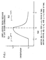
- all slug feeding of additives may be carried out on the basis of duration of feeding time defined as t f - t i and frequency of feeding time defined as t f 1 - t i . Both time periods are specific for specific systems and are illustrated in Figure 1.
- contingency plans can be built into the preceding logic in order to detect and compensate for ingressors and upsets, thus avoiding a loss of control of the performance parameter set points.
- Example 2 presents an analysis of a cooling tower system in which one or more intermittent water make-up streams are supplied to the system in addition to the main make-up stream.
- various sources and types of water are available and are provided to cooling tower systems.
- this water constitutes the main make-up stream.
- Other sources of make-up water may be available on an intermittent basis and, therefore, are provided intermittently.
- One intermittent stream may be provided or several intermittent streams may be provided simultaneously. These intermittent streams will in all likelihood be of different quality from each other as well as from the main make-up stream.
- Example 2 may be utilized to develop feed forward control of blowdown and consistent control of cycles of concentration. Also, Example 2 compiles input data, which forms the basis upon which other algorithms may be utilized as feedback control.
- This example provides an analysis of a cooling tower system in which there are one or more intermittent make-up streams provided to the system in addition to the main make-up water stream.
- a simple model of the system is proposed.
- a computer program is presented that has two options. One option is used to determine required blowdown flow rate so that there is no change in the cooling system concentration when the intermittent stream(s) flow into the system. With a second option, the quality of the water in the system can be determined as a function of time. Provision is made to vary the blowdown from the system in order to determine the effect of various blowdown rates.
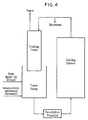
- Fig. 4 represents a simple model of a portion of cooling system involved in this example.
- Fig. 4 illustrates a cooling tower system. The system is supplied with a main make-up water supply. Intermittent additional stream(s) are provided periodically.
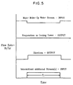
- Fig. 5 schematically illustrates a rate of flow of input streams to the system and output streams from the system as a function of time.
- Fig. 5 shows that an intermittent stream or streams flow into the system for a period of time, T 1 .
- the system is in equilibrium before the start of the intermittent stream(s). It is also assumed that the rate of evaporation in the cooling tower remains constant during the time that the intermittent stream(s) are flowing.
- the blowdown from the system may be adjusted to maintain the original water quality in the system.
- the flow of the main make-up stream may be adjusted so that the constancy of the evaporation rate in the cooling tower is maintained. That is, flows may be adjusted so that the total water hold-up in the system remains constant.
- the total amount of coolant, such as water, in a cooling system typically is maintained constant.
- One way to achieve this is to utilize the cooling tower basin level as the make-up control. This may be carried out by controlling the main make-up stream with a float valve. Streams other than the make-up stream are permitted to flow into the system at their available rate(s). If the other streams provide sufficient water, then the main make-up stream typically is not actuated. Also, multiple make-up streams typically have little or no effect on the evaporation rate or its consistency.
- Fig. 5 also shows the streams entering and leaving the system.
- the evaporation in the cooling tower is assumed to be constant.
- the blowdown may be adjusted to maintain the quality of the water in the system.
- the flow of the main make-up stream may then be adjusted to satisfy the constancy of the evaporation rate.
- the system may be analyzed by making water and component balances around the whole system as well as around the cooling tower sump. When the intermittent stream(s) start to flow into the system it is assumed that the system is in equilibrium.
- Option No. 1 of the computer program may be utilized to determine the required blowdown flow rate so that the water quality in the system remains unchanged when the intermittent stream(s) flow into the system.
- Option No. 2 of the computer program may be utilized to determine the concentration as a function of time for various blowdown flow rates.
- the problem becomes an unsteady state problem and it is necessary to make the material balances over an infinitesimal time increment.
- This results in differential equations, the solution of which will give the water quality as a function of time both during and after the intermittent stream(s) flow into the system.
- the calculations will start at the time when the intermittent stream(s) begin flowing into the system.
- the result of the calculations will be to give the concentration of a key constituent in the water as a function of time.
- the component concentration referred to is that of a key water quality component such as hardness, total dissolved solids, silica, etc.
- INPUT main make-up stream
- MMMUI OUTPUT water vapor from cooling tower
- MMAUT - MVAP - MBDI 0
- this value represents windage, uncontrolled liquid losses, and blowdown.
- Windage, or drift represents moisture entrained in vapor (evaporation). Windage is a function of cooling tower design and is typically expressed as a percentage of circulation rate. Uncontrolled liquid losses can include pump seals and other such means. While windage and uncontrolled liquid losses are both uncontrollable, blowdown may be controllable. While uncontrolled liquid losses and windage may be relatively constant, blowdown is a valid means for controlling cycles of concentration of solids in circulating cooling water.
- the flow rate of the blowdown should be determined so that there is no change in the water quality due to the intermittent stream(s) . That is, the initial system concentration, CSYSI, is assumed to remain constant.
- INPUT main make-up stream
- MMMU INPUT Intermittent stream(s)
- Equation (3) and Equation (4) above may be utilized to determine the blowdown flow rate and the main make-up stream flow rate so that there will be no change in the concentration of the water in the system when the intermittent stream(s) start to flow.
- the concentration of the system may vary with time. This may present an unsteady state problem and typically is analyzed using differential time elements.
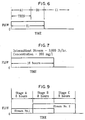
- Residence time, TRES, of water in cooling system is less than the duration of flow, T 1 , of the intermittent stream (s) (See Fig. 6).
- T T 1
- INPUT (main makeup stream) (MMMUI) (CMMU) dT
- INPUT (cooling tower) (MSYS - MBDI) ((CSYS) T-TRES ) dT
- Residence time, TRES, of water in the cooling system is greater than the duration of flow, T 1 , of the intermittent stream (See Fig. 7).
- INPUT (main make-up stream) (MMMU)(CMMU)dT
- INPUT (intermittent stream(s)) (MIAS)(CIAS)dT
- INPUT (main make-up stream) (MMMUI) (CMMU) dT
- the computer program uses the equations presented above.
- the intermittent stream is shown in Fig. 7. Its flow rate is 3,000 lb/hr, its concentration is 300 mg/l and it flows for a period of 16 hours.
- Option No. 1 The calculations for Option No. 1 give the blowdown rate and main make-up rate so that there is no change in the system concentration. That is, CSYSI remains at 500 mg/l.
- the following represent data included in a printout for Option No. 1. The data indicates that the required blowdown and main make-up stream flow rates are 2,500 and 3,500 lb/hr.
- Table 1 shows that as the blowdown rate is increased, the concentration at the end of the flow of the intermittent stream (16 hr) decreases and becomes equal to the equilibrium value (500 mg/l) when the blowdown flow rate is 2500 lb/hr. This agrees with the results obtained in Option No. 1. Also, as the blowdown rate increases, the rate of flow of the main make-up stream increases to maintain the constant hold-up of water in the system.
- Fig. 8 represents a plot of sump concentration versus time for four different blowdown rates. When the intermittent stream begins flowing into the sump the concentration increases immediately but as blowdown rate increases the rate of increase of the concentration decreases and finally becomes zero when the blowdown rate is 2,500 lb/hr as indicated in Table 1.
- STORED DATA CONCENTRATION OF THE MAIN MAKE-UP STREAM (mg/l) 100.
- INITIAL SYSTEM CONCENTRATION (mg/l) 500.
- INITIAL FLOW RATE OF BLOWDOWN (lb/hr) 1,000.
- INITIAL FLOW RATE OF MAIN MAKE-UP STREAM (lb/hr) 5,000.
- TEMPERATURE OF THE WATER IN THE SUMP 85.
- VOLUME OF WATER IN COOLING SYSTEM (cu. ft.) 1,000.
- VOLUME OF WATER IN THE COOLING TOWER SUMP (cu. ft.) 1,000.
- the intermittent streams are shown in Fig. 9.
- the flow rate of Stream No. 1 is 1,000 lb/hr, its concentration is 300 mg/l and it flows for a period of 16 hours.
- the flow rate of Stream No. 2 is 2,000 lb/hr, its concentration is 50 mg/l and it flows for a period of 16 hours.
- Stream No. 2 starts to flow into the sump 8 hours after Stream No. 1 starts to flow.
- the two streams are flowing simultaneously into the sump.
- a blowdown rate is determined for which the concentration in the tower sump is equal to that which existed at equilibrium, i.e., 500 mg/l.
Landscapes
- General Physics & Mathematics (AREA)
- Engineering & Computer Science (AREA)
- Automation & Control Theory (AREA)
- Physics & Mathematics (AREA)
- Preventing Corrosion Or Incrustation Of Metals (AREA)
- Testing And Monitoring For Control Systems (AREA)
- Supply And Distribution Of Alternating Current (AREA)
- Fluid-Pressure Circuits (AREA)
- Feedback Control In General (AREA)
- Testing Resistance To Weather, Investigating Materials By Mechanical Methods (AREA)
- Earth Drilling (AREA)
- Prevention Of Electric Corrosion (AREA)
- Valve Device For Special Equipments (AREA)
- Exchange Systems With Centralized Control (AREA)
- Selective Calling Equipment (AREA)
- Control Of Steam Boilers And Waste-Gas Boilers (AREA)
- Control Of Non-Electrical Variables (AREA)
Abstract
Description
- The invention relates to a method for controlling chemical treatment and water quality within cooling systems by measuring corrosion and fouling to adjust treatment control parameters in the cooling systems. Furthermore, the invention relates to a corresponding article of manufacture.
- The purpose of a cooling system is to remove heat from a process and discharge that heat to the environment through evaporation and liquid discharge. An example of such systems are cooling water systems used to remove heat from a turbine-condenser. Removing the heat causes steam to condense, resulting in a pressure reduction on the steam-condensate side of the condenser, and an increase in the amount of power generated per unit of fuel used to produce the steam. Similarly, another example of such a system is a refrigeration machine. Such a machine may utilize a refrigerant, such as R-11, R-12 or R-134A, to extract heat from a chilled medium, such as water, loop and transfer the heat to a cooling system.
- Another example of a cooling system is one in which heat from a process or series of processes may be transferred to the cooling medium through a process heat exchanger, such as an intercooler on an gas compressor. The operating efficiency of a multi-stage gas compressor, such as an oxygen or nitrogen compressor, may be directly tied to the temperature and pressure of the gas stream entering each stage of the compressor. The higher the temperature and pressure above design conditions, the more power will be required to compress the same amount of gas.
- According to one example of a cooling system, the cooling medium includes a liquid, such as water. Such a cooling system may comprise (1) at least one heat exchanger for removing heat from one or more processes; (2) at least one pump for circulating the cooling medium through the at least ono heat exchanger; (3) means for cooling the cooling medium, such as a cooling tower; (4) means for adding new cooling medium to the system, such means is typically referred to as make-up; and (5) means for discharging a certain amount of cooling medium from the system, such discharge is referred, to as blowdown.
- The cooling effect according to such a system may be achieved by evaporating a fraction of the cooling medium into a stream of air as the cooling medium passes over the cooling tower. During the process of removing heat from the cooling medium, unsaturated air may enter the cooling tower. The unsaturated air may pick up the evaporated fluid and exit the cooling tower at a higher temperature and in a saturated state with respect to the cooling:medium.
- According to another example of a cooling system, a cooling medium, such as water, may be obtained from a large reservoir of the medium that will provide an adequate supply of the cooling medium at a temperature low enough to absorb heat from a process or processes via at least one heat exchanger. In such an example, the cooling system may include (1) a source for the cooling medium; (2) means for circulating the cooling medium, such as at least one circulating pump; (3) at least one heat exchanger; and (5) a place to discharge the heated cooling medium, such as the same body of cooling medium as the source.
- Cooling systems that employ liquid cooling media may be subject to deposition of foulant materials and processes, such as hardness salts, corrosion products, biomass, silt, and mud from the cooling medium, various process leaks, and in-situ corrosion. These foulant materials and processes may be input into the cooling systems from a variety of sources.
- Certain treatment materials may be added to the cooling medium or cooling system to inhibit, among other things, hardness deposition, corrosion, formation of biomasses, and agglomeration of other foulants such as silt, mud, corrosion products and process leaks. Such treatment materials may include one or more chemical components that, in combination, effectively inhibit one or more of the above mentioned problems. For example, a treatment material designed to inhibit corrosion may include at least one cathodic inhibitor, at least one anodic inhibitor, and/or at least one additional material, such as anti-scalant(s), surfactant(s) and anti-foam agent(s). Other treatment materials that may be added to the system/medium may include one or more acids, such as sulfuric acid, or one or more alkaline materials, such as a solution of caustic soda. These additional materials may control the pH of the cooling medium within a predetermined control range. When controlling the pH, the acid would be used to lower the pH and the alkali to raise it.
- Typically, the amount of treatment material(s) added to the system/medium may be determined by manual laboratory tests, corrosion coupon analyses, the volume of cooling medium in the system and the amount of cooling medium supplied to the system in a given period of time. In such cases, means, such as a chemical injection pump, may be used for injecting a flow of a treatment material into the system at a constant rate over time.
- When adding material(s) to adjust pH, a closed loop chemical injection system may be utilized. For example, the system pH may be monitored by a pH monitoring device that controls a pump or valve to increase or decrease the feed of the pH adjusting agent(s).
- Treatment materials used to inhibit the deleterious effects of process leaks are typically controlled manually, either on a continuous basis or upon detection of the occurrence of such a leak. Detecting, locating and quantifying a process leak is a time consuming task that may be performed by a plant operator or treatment professional.
- Another important aspect of treatment and control of a cooling system and the quality of the cooling medium relates to maintaining the concentration of dissolved and suspended materials in the medium below the level at which they may precipitate or agglomerate. This is typically accomplished by adjusting the amount of concentrated cooling medium removed from the system via blowdown. Typically, this has been done by manual adjustment of a blowdown valve, based on laboratory analysis of the circulating cooling medium. More recently, blowdown has been automated by monitoring the specific conductivity of the cooling medium and adjusting a blowdown valve to maintain a specified range of conductivity within the system.
- Typically, a cooling system includes a cooling medium, such as water. The characteristics or properties of the cooling medium may affect the cooling system and its operation. Cooling medium parameters such as pH, conductivity, corrosion rates, temperatures (such as cold supply, hot return, heat exchanger inlet, and outlet, among others), cooling medium recirculation rate, cooling medium make-up rate and cooling medium blowdown rate have long been monitored to control the characteristics of the cooling medium. Blowdown may serve to deconcentrate the dissolved solids in the cooling medium and the makeup replaces all cooling medium losses, including those from evaporation, windage, drift and blowdown. Historically, automated control of cooling systems has been based upon on-line measurements of conductivity and pH, for example. Measurements of these parameters may be supplemented by laboratory wet chemistry tests for residual inhibitor level and other parameters relevant to the specific application.
- The use of linear polarization resistance technology for on-line measurement of corrosion rates was previously disclosed in U.S. patent numbers 3,069,322, 3,156,631, 3,250,689, 3,607,673 and 3,698,065. In U.S. patent numbers 4,339,945, to Knudsen, and 4,346,587, to Knudsen et al., a methodology was disclosed where in a device in which the measurement of fouling added to pH, conductivity and corrosion is disclosed and applied to determine the effectiveness of a treatment regime in inhibiting corrosion and fouling in fluid systems, such as cooling water. Since corrosion may decrease the economic life of equipment in the cooling system and fouling may reduce the efficiency of heat rejection from plant processes to the cooling medium, it is very important to keep these under control.
- Traditional control of open recycling cooling systems typically includes the use of a single loop controller for controlling the pH with either an acid, such as sulfuric acid, or a base, such as a solution of caustic soda. A single loop controller may be included for controlling the level of dissolved solids in the cooling medium. Such dissolved solids may be measured by specific conductivity, and may be increased or decreased via adjusting a blowdown, or bleed off valve. Increasing the rate of bleed off causes the dissolved solids in the cooling medium to decrease. Some type of feed control for treatment chemicals may also be utilized for controlling the characteristics of cooling systems. Calendar date and time combined with an interval timer function are commonly utilized in control of systems and, in particular, for adding various types of microbicides.
- Control of pH and conductivity typically utilizes feedback control technology. Feedback control may provide either analog or digital outputs to operating equipment such as pumps and valves. Analog outputs may go through Proportional Integral Derivative (PID) controllers for more precise control. Make-up medium flow rate, the flow rate of cooling medium added to the system compensate for medium lost to evaporation and other losses, such as windage and blowdown, is typically the basic control parameter for feed of treatment chemicals such as inhibitors and dispersants. In a cooling system, and an aqueous cooling system in particular, the make-up medium may be water supplied from at least one source, such as potable municipal water, well water, reclaimed process water, externally treated water, and condensate. Another commonly used, but less precise, method is to use the blowdown medium flow rate, which requires an assumption that other liquid losses may be either fixed or proportional to blowdown. A third means is called "bleed and feed", which proportions the addition of treatment materials to the time that an on/off, for example, a solenoid, bleedoff or blowdown valve is actuated.
- Linear Polarization Resistance (LPR) technology has been used for three decades to monitor corrosion rates on-line. This technology is marketed as a "CORRATER" monitor by Rohrback Cosasco Systems, Inc. The analog signals provided by the CORRATER monitor are proportional to the "instantaneous" corrosion rate or the "instantaneous" corrosion imbalance. In fact, the CORRATER monitors determine the LPR over a period of time that may be as little as about 2 minutes or as long as about 20 minutes. Thus "instantaneous" is a relative term when compared with off-line techniques, which may require about 30 to about 90 days of coupon exposure and as compared to on-line electrical resistance techniques, which may require about 2 to about 30 days.
- Fouling Factor (FF) is a recognized engineering unit of measure. The FF results from the deposition of foulants on a heat transfer surface. The P-U-L-S-E analyzer, available from Ashland chemical, Drew Industrial Division, provides the ability to determine the FF. The ONGUARD CFM-1000 monitor, also available from Ashland Chemical, Drew Industrial Division, determines a Fouling Index (FI). Research has proven that FI and FF have identical trends, yet they are numerically different and are computed in different manners.
- Known methods of monitoring characteristics of cooling systems and controlling parameters of the systems may be of three types. The first type includes those that have traditionally lent themselves to automated feedback control of certain parameters, such as pH for the control of acid or caustic feed and conductivity for the control of bleedoff or blowdown.
- The second type are those that detect the residual of a specific component in the treatment chemistry where such can be adequately measured in such a stream of the cooling medium. There are two known approaches to this type of monitoring. The first approach includes detecting a single active component, while the second type of detecting includes detecting an inert material that acts as a tracer.
- Phosphate monitors are examples of the first approach to detecting since they detect only a single species of phosphorous ion, orthophosphate, in the cooling water system. In fact, the treatment chemistry may include several different phosphorous bearing materials together with various polymers, aromatic azoles and other constituents.
- In the presence of calcium, magnesium, ferrous and ferric ions, orthophosphates have limited solubility. The limited solubility is a complex function of pH, temperature, residence time, and ionic concentration. In some systems, the solubility of such materials under operating temperatures and pressures may be close to the desired control limits making it difficult to differentiate between an excessive feed and conditions that may lead to deposition and, ultimately, to under deposit corrosion, which, in addition, leads to control windup.
- Use of an inert tracer compound that, unlike the active materials, can be detected in the stream of the cooling medium has its own shortcomings because it may only tell the user how much tracer material is in the system. It may be unable to determine the efficacy of the treatment. For example, a treatment material, such as active constituents in a corrosion inhibiting composition, typically is consumed by reaction(s) in the process of inhibiting corrosion, or whatever process it is directed to inhibiting. The remaining treatment material is that portion that the reaction(s) do not consume and/or residual portion(s) that are required to sustain the involved reaction(s) by driving them to completion. Inert material(s), on the other hand, pass through the system without reacting with anything. This dependence on tracer components does not assure the maintenance of active components within the desired control limits to assure that the performance benefits of said active components are derived. The above discussion may apply to any treatment material.
- Other monitoring techniques include off-line monitoring such as complete chemical and microbiological analysis of the circulating water and analysis of corrosion coupons.
- Many automated chemical feed systems utilize closed loop feed forward logic. These approaches use measured variables such as flow rate changes and changes in pressure, such as a pressure drop. The chemical feed quantities are adjusted through mass balance based algorithms associated with these measured variables. Further improvements were made in the accuracy of the mass balance algorithms by utilizing secondary measurements of conductivity and pH. However, these chemical feed systems only assured chemical mass loading maintenance within the system and did not take into account losses of the additives due to reactive consumption, precipitation or adsorption.
- Other technologies were developed to feed chemicals based upon detection of quantifiable traceable entities associated with the chemical fed. While this approach alone ensured chemical quantity presence over the preceding method or in conjunction with preceding method whereby the method was utilized as a feed back trim. Approaches to date have not ensured the maintenance of key performance variables. For example, the key performance variables in cooling water systems are corrosion and fouling.
- The minimization of the degree of corrosion and fouling in cooling waters are dependent upon the site-specific make-up water characteristics, system design and operational criteria. As a result, a plurality of chemicals may be required to maintain a cooling system's corrosion and fouling control. Chemicals such as and not limited to ferrous and non-ferrous corrosion inhibitors, scale control agents, dispersants for inorganic and organic foulants, oxidizing and non-oxidizing biocides, biodispersants as well as specialized contingency chemicals to handle chemistry upsets due to process side ingressors. Should all these additives contain a tagged tracer to the active ingredient(s) or an inert tracer proportional concentration of the active ingredient(s), they could be separated individually for quantification as to the amount of each present in the system water utilizing on-line monitoring techniques, such as calorimetric, U.V., fluoromatic, among others.
- However, with such feed back trims in place, there still exists a lack of linkage of chemical(s) addition to the key performance variables, which are impacted by the chemicals. Examples of such systems include the system disclosed by Canadian Patent 2,055,098. United States Patent numbers 5,006,311, 4,992,380 and 4,783,314, which illustrate the process of detection of tracer tagged additives. These on-line detection methods then permit an increase, below specification, or decrease, above specification, in dosing rates of the detected additive. Should the additive be depleted from process inleakage or sludge adsorption for example, then continuous overfeed of the additive would occur. The residual loss and/or maintenance are not deriving any key performance value as it is not part of additive's designed intended use. Thus, control wind up results in an uneconomical consumption of the additive which in fact could impact the key performance variables negatively, such as increased fouling and/or corrosion.
- Another example of such a system is disclosed by Rohm and Haas Company of Philadelphia, Pennsylvania, who have refined the traced tagged polymer approach as outlined in their literature from 18358B, Bulletin FC415. The method revealed therein indicates that free/unreacted polymer rather than total polymer can be detected by laboratory bench testing means. Unfortunately, this too can lead to control wind up whereby if system operational design or process inleakage occurs, the corrosion inhibitor, phosphate, will be lost in heat exchanger surface deposition, necessitating increased phosphate and tagged polymer addition. Not only is fouling increased but also underdeposit corrosion is initiated. This method again is not linked to key performance parameters of the system being treated. Only the economics associated to overfeed are reduced slightly over the previous citing and at present the method cannot be performed on-line and coupled to automatic chemical feeding as the former.
- Yet another system is disclosed by United States Patent numbers 4,966,711 and 5,200,106, which teach the use of inert transition metals for tracers. These tracers are added in Proportion to a chemical additive package. Should the additive(s) be consumed or lost due to coprecipitation or adsorption fouling then the tracer would indicate sufficient additive is present when in fact the opposite is true. This then results in control wind down. Corrosion protection can then be compromised. The key performance parameters of the system are not addressed.
- Ion selective electrodes can and have been utilized to detect both inert tracers and corrosion inhibitors, such as phosphate. Inert tracer detection can lead to control wind down, while corrosion inhibitor detection of said phosphate can lead to control wind ups as previously mentioned.
- United States Patent number 5,272,346 disclosed that certain corrosion control additives which are sensitive to U.V. absorption, such as imidazoline and pyridine derivatives, can be monitored on-line. However, no attempt in correlating the key performance parameter of corrosion rate determination and the impacted detectable amounts of the corrosion control additive have been disclosed. Should the relationship be established, again there is no assurance that an increase or decrease in additive concentrations would produce the desired result of improvements in the corrosion control as other foulants or conditions may be impacting the on-line corrosion rate being monitored.
- Utilization of traced non-oxidizing biocides has also been proposed by Cooling Tower Instituted of Houston, Texas, Cooling Tower Water Chemistry Paper T.P. 95-16. This approach allows the user to ensure that a residual amount of biocide additive in the system water over the period of desired contact time is correct. It does not relate to the control of the microbiological population, such as efficacious kill rates, and more importantly is not related to the detection and mitigation of biological fouling or microbiological influenced corrosion. Again, the key performance parameters are not addressed, which are, in fact, related to the need and use of the biocidal additives if smart logic can be used for the on-line identification of the use need.
- The above discussion reveals that such approaches, at best, may permit a user to cross check chemical feed(s) based on mass balance, feed forward, and trim the specified amounts based on the on-line detection of the actives, feedback. This may allow for the potential of chemical inventory and economic control in a dynamic perfect system. Under upset or loss conditions, there is a potential for poor economics.
- According to one analysis, the approximate operating costs of a cooling system, excluding downtime opportunity costs, may be broken down as follows:
Cost Category Percentage of Total Operating Costs Electricity 59 Equipment Depreciation 17 Labor 14 Maintenance 5 Water Sewerage 3 Water Treatment Management 2 - The above-discussed approaches may impact the water treatment management portion and allow a user some ability to optimize the 2% of the cooling system cost. However, without linkage to the key performance parameters the remaining 98% of the operating costs cannot be effectively impacted. It is also well known that ineffective water treatment can lead to an increased operating cost of 4 to 5 times the cost of effective water treatment in simple refrigeration cycle cooling systems. Clearly, there is a need for a control system, which is linked to site specific key performance parameters through smart logic.
- The effects of make-up coolant flow, contaminants in cooling systems and ingressors may not be directly measured or their effects directly predicted. However, the inventors of the present invention have discovered that accumulated effects of the above problems may be indirectly measured through measuring at least one of a variety of factors. The present invention relates to a method and an article of manufacture that provide direct real time links between selected parameters and mechanical operations of an aqueous system. The parameters may include performance indicators and controlled variables related to the cooling system.
- In accordance with its objects and advantages, aspects of the present invention provide a method for monitoring and controlling an aqueous system, the method comprising the steps of:
- measuring corrosion rate over a period of time;
- A) if corrosion rate does not change then measuring fouling factor or fouling index;
- I) if fouling factor or fouling index does not change from a setpoint then commencing the method again by measuring corrosion rate;
- II) if fouling factor or fouling index deviates from the setpoint then add a material stepwise to the aqueous system to adjust fouling factor or fouling index to the setpoint, and measure pH and add a material to the aqueous system to adjust pH if pH deviates from a setpoint, and commencing the method again by measuring corrosion rate;
- B) if corrosion rate is decreasing, measure oxidation-reduction potential over a period of time ;
- I) if oxidation-reduction potential does not change then reduce feed rate of a corrosion inhibitor and commence the method again by measuring corrosion rate ;
- II) if oxidation-reduction potential decreases then measure fouling factor or fouling index;
- a) if a change in fouling factor or fouling index from the setpoint is detected, then determine the rate of change and control feed of treatment materials affecting oxidation-reduction potential and fouling until desired levels are obtained, then commence the method again by measuring corrosion rate;
- b) if a change in fouling factor or fouling index from the setpoint is not detected then increase a feed rate of a halogen based oxidant into the aqueous system and then measure oxidation-reduction potential again;
- i) if oxidation-reduction potential is at a setpoint then commence the method again by measuring corrosion rate;
- ii) if oxidation-reduction potential deviates from the setpoint then go to step (B) (II) (a);
- C) if corrosion rate increases then measure instability in the corrosion rate;
- I) if instability in corrosion rate is not detected, measure pH and add a material to the aqueous system to adjust pH if pH deviates from a setpoint, increase a feed rate of corrosion inhibitor, and commence the method again by measuring corrosion rate;
- II) if instability in corrosion rate is detected then measure fouling;
- a) if fouling is not detected then measure pH and add a material to the aqueous system to adjust pH if pH deviates from a setpoint, increase feed rate of corrosion inhibitor, and determine if instability remains in the corrosion rate;
- i) if no instability in corrosion rate is detected then commence the method again by measuring corrosion rate;
- ii) if instability in corrosion rate is detected then add material to the system to control fouling until fouling reaches a setpoint then determine if instability remains in the corrosion rate;
- 1) if instability in corrosion rate is not detected then commence the method again by measuring corrosion rate;
- 2) if instability in corrosion rate is detected then return to step (C) (II) (a);
- b) if fouling is detected then determine whether fouling factor or fouling index or corrosion rate first deviated from a setpoint;
- i) if corrosion first deviated from a setpoint, then go to step (C) (II) (a);
- ii) if fouling factor or fouling index first deviated from a setpoint then take at least one action including adding dispersant material to the aqueous system to reduce fouling and adjust operating parameters of the aqueous system then commence the method again by measuring corrosion rate.
- a) if fouling is not detected then measure pH and add a material to the aqueous system to adjust pH if pH deviates from a setpoint, increase feed rate of corrosion inhibitor, and determine if instability remains in the corrosion rate;
- A) if corrosion rate does not change then measuring fouling factor or fouling index;
- In a further aspect the invention relates to an article of manufacture for use in programming a processor having at least one output device and data storage device attached thereto, the article of manufacture including a processor-readable medium having one or more programs embodied therein for performing the method according to the invention.
- Still other objects and advantages of the present invention will become readily apparent by those skilled in the art from the following detailed description, wherein it is shown and described only the preferred embodiments of the invention, simply by way of illustration of the best mode contemplated of carrying out the invention. As will be realized, the invention is capable of other and different embodiments, and its several details are capable of modifications in various obvious respects, without departing from the invention. Accordingly, the drawings and description are to be regarded as illustrative in nature and not as restrictive.
- The above-mentioned objects and advantages of the present invention will be more clearly understood when considered in conjunction with the accompanying drawings, in which:
- Fig. 1 represents a graph that illustrates a relationship between concentration of a material in an aqueous system with respect to time;
- Fig. 2 represents a graph that illustrates a relationship between an independent variable concentration of a material in an aqueous system with respect to time and the effects of an embodiment of a step-wise control system according to the present invention;
- Fig. 3 represents a flow chart that illustrates an embodiment of a decision making process according to the present invention;
- Fig. 4 represents a schematic view of an example of a cooling tower system that the present invention may be utilized with;
- Fig. 5 represents a graph that illustrates flow rates of input streams flowing into and output streams flowing out of a cooling tower system with respect to time;
- Fig. 6 represents a graph that illustrates flow of intermittent stream(s) and various time periods during which a process according to the present invention may be utilized to analyze;
- Fig. 7 represents a graph that illustrates flow of an intermittent stream into a cooling system;
- Fig. 8 represents a graph that illustrates a relationship between tower sump concentration and time in a cooling system; and
- Fig. 9 represents a graph that illustrates flow of two intermittent streams into a cooling system.
- The present invention provides a novel closed-loop performance-based control system. This present invention is related to South African patent application ZA 9701350 dealing with Performance-Based Control System, the entire contents of the disclosure of which is hereby incorporated by reference. While South African patent application ZA 9701350 made great strides in the control of cooling systems, the present invention furthers the previous system by providing a direct, real-time link between one or more performance parameters and at least one controlled variable. As such, the present invention integrates the performance parameters into the control system. The present invention, also provides algorithms that serve as the basis for automated control of systems by linking changes in the performance parameters on a real time basis into control system.
- South African patent application ZA 9701350 discloses a performance based control system utilizing continuous fouling and corrosion on-line measurements as open loop cascade control technology. This method exhibits superior key performance variable, such as fouling and corrosion, control maintenance over the above-discussed methods, provided the increased fouling is inorganic in nature and the increased corrosion is derived from corrosion inhibitor concentration variations. Since the effects of make-up contaminants and ingressors can neither be directly measured nor their efforts be directly predicted, the accumulated effects of the preceding on the key performance instantaneous/monitoring of corrosion, fouling, pH and ORP. Measurement data can be compared to baseline conditions and the effects, indirectly predicted. These predictions provide real time links between the measured key performance indicators and controlled variables such as treatment chemistry, fluid make-up, fluid volume, operating temperatures, mechanical operations such as filter backwash, various methods for on-line cleaning of heat exchangers, thermal bypasses, booster pumps, among other variables.
- The present invention utilizes the predictive logic applied to a closed feedback-trimming loop of chemical selection, addition frequency and amount metered to maintain the desired key performance parameters within desired specifications. Desired specification herein includes control of corrosion and fouling to specified limits, which are selected by the user to match both system design and operational characteristics, balance the economics associated with the cost of the system operation and any lost cost opportunities associated with downtime.
- According to one example, they may be defines as follows:
Fouling Allowance 0.001 hr·ft 2·°F/Btu or 100 hr·ft2·°F/Btu x 10-5 Corrosion Allowance Mild Steel 2 mpy or less Admiralty Brass 0.3 mpy or less Conditions No pitting or underdeposit corrosion - The teachings of Noyes Publications Text, Fouling of Heat Exchangers, Characteristics, Cost, Prevention, Control and Removal, (© 1985, ISBN: 0-8155-1016-0)
Chapter 2, Overview of Fouling, the entire contents of the disclosure of which is hereby incorporated by reference, outlines the Conditions of Fouling that are duplicated by Ashland Inc.'s P-U-L-S-E technology and the Types of Fouling that can be reasoned into separation logic for its detection and mitigation with the current invention. - When dealing with open evaporative cooling systems, there are two categories of concern typically associated with water quality, namely, corrosion and fouling. The present invention identifies in these two categories three subsets of indicators for identification through separation logic techniques. The instantaneous monitor trends are the basis for separation and identification of the independent variable stepwise adjustment outputs.
- The following properties and relationships have been discovered to exist:
- I. Corrosion
- a) General corrosion may be tied to the corrosion inhibitor concentration and pH present in the operating system water.
- b) Pitting corrosion again may be, tied to the previous conditions (a) in a more aggressive manner whereby prefilming or refilming is required. It may also lead or be the precursor to underdeposit corrosion and corrosion product fouling.
- c) Underdeposit corrosion may be tied to the previous conditions (b) but an advancement of condition b or biological fouling.
- II. Fouling
- a) Inorganic fouling may be either particulate in nature, which has no time delay when monitoring, or crystalline in nature, which does have a time delay when monitoring. Particulate fouling can lead to underdeposit corrosion and, hence, instability in the instantaneous corrosion monitor data.
- b) Organic fouling may have no time delay when monitoring and occurs when the other specific monitoring variables such as Total Organic Carbon or Chemical Oxygen Demand increase, oxidation reduction potentials decrease and corrosion rates decrease with a potential for corrosion rate instability presence.
- c) Biofouling may have a time delay associated with an initial increase in corrosion rate followed by instability in the corrosion measurements as the general corrosion rates begin to fall. This delay time may be short compared to true corrosion product fouling and the onset of fouling can initially produce negative heat transfer resistance, that is fouling factors, depending upon the fouling monitor metallurgy roughness factor.
- From the above, it has been deduced that:
- 1. General corrosion and inorganic crystallization fouling can be the simplest forms to separate since they appear to be independent of each other.
- 2. Pitting and non-inorganic fouling should be avoided since they have an interdependent relationship.
- 3. Pitting can lead to:
- i) underdeposit corrosion
- ii) microbiological influenced corrosion, which can lead to underdeposit corrosion (NACE Corrosion/95, Paper 201).
- iii) microbiological influenced corrosion, which can lead to pitting, which can lead to underdeposit corrosion.
- 4. Microbiologically influenced corrosion can lead to inorganic entrapment fouling inclusions.
- 5. Organic fouling can lead to inorganic entrapment fouling inclusions.
- 6. organic fouling can lead to microbiologically influenced corrosion, which can lead to inorganic entrapment fouling inclusions.
- 7. Pitting corrosion can lead to microbiologically influenced corrosion and inorganic entrapment fouling inclusions. This is due to hydrogen uptake by bacteria at the cathodic site of the corrosion cell.
- 8. Inorganic particulate fouling can lead to underdeposit corrosion, which may induce microbiologically influenced corrosion.
- According to the present invention, points, or caveats, 1 through 8 discussed above are addressed through smart logic, or artificial intelligence. The logic can identify the cause for the key performance parameter change from the specified set point through input feed back from linear polarization, fouling monitor, pH and/or ORP instrumentation installed on the recirculatory water system. It may then select the appropriate additive or operational change and verify the improvement via a time function, equation 4 below.
- When the key performance parameter change is less time, t, as defined by
equation 3, which is site specific, it is also determined that the upset is externally derived from the dynamic system. Examples of externally induced upsets include, for example, change from performance parameter set point, are a change in make-up water chemistry, atmospheric, for example, airborne, contamination or process inleakage contamination. - According to the present invention, the economics of the upsets can also be evaluated in real.time. Data can be logged in separate files during the alarmed upset whereby the performance parameters are maintained at the specified set points and the associated chemical inventories consumed to achieve this are itemized. This data can then be used to evaluate the upcharged cost compared to process throughput reduction, labor, parts, and downtime opportunity cost potentials. Such analysis can then be used to determine if a relaxation in the specified set points of the key performance parameters would provide further economic benefit.
- Any performance parameter may be utilized according to the present invention. The performance parameters include fouling, corrosion, and oxidation-reduction Among the controlled, or controllable, variables that may be utilized are treatment chemistries, such as feed rates of acid, caustic, corrosion inhibitor, dispersant, oxidizing microbicide, and non-oxidizing microbicide. The controllable variables may also include blowdown rate, side stream filter backwash, make-up flow, fluid volume, operating temperatures, and/or mechanical operations, such as filter backwash and methods for on-line cleaning of heat exchangers, thermal bypasses, booster pumps, among other elements of the system.
- The present invention may be utilized with a variety of systems, not limited to cooling systems. For example, the present invention may be utilized with any aqueous system to monitor and control water quality. Among the systems that the present invention may be utilized with are mine waters, waste waters, pulp streams, paper streams, deep well injection, and geothermal processes. The present invention may be utilized with closed loop and feedback control systems.
- By interrelating performance parameters, controllable variables, and mechanical operations, the present invention raises monitoring and control to a new level. Monitored changes in variables are utilized to monitor for undesired movements in performance parameters and can then be utilized to trigger a variety of actions.
- The dynamic response of open recirculating water systems may be characterized by the following equations:


where - y represents a concentration of a measured inert material added to the system at a constant proportion to mak-up;
- y' represents a concentration of a measured inert material when no further addition is made to the system;
- x represents time;
- b represents a base line measured variable;
- a represents a constant derived from a statistical curve fit of y versus t when y increases;
- a' represents a constant derived from a statistical curve fit of y versus t when y' decreases.
- Aqueous systems may further be characterized by the following equation:

where - t represents an initial response time of the aqueous system to changes in a variable;
- 1 represents liquid losses, such as through blowdown and drift, which are equivalent to make-up cycle;
- V represents system volume;
- Cf represents final concentration of the measured inert material ; and
- Ci represents initial concentration of the measured inert material.
- Additionally, aqueous systems may be characterized by the following equation:

where - Ψ represents a period expected for a performance parameter to respond to a change made in the aqueous system; and
- t' represents time expected to obtain full response to the change in the aqueous system.
- According to equation 4, ψ is characteristic of the parameter to be controlled and the system dynamics which are defined, for a specific system, by
equations - Thus, a measurable inert substance may be used to characterize the dynamics of any open recirculating water system by first adding the substance at a constant proportion to make-up, while measuring said parameter against time until the concentration ceases to change significantly. Concentration versus time is then plotted and
equation 1 is used to curve fit, thus determining a. The addition of the inert substance is then terminated and its concentration is then measured and plotted against time.Equation 2 is then used to curve fit, thus determining a'. - If, after a period of time, t', the control system is unable to maintain the desired performance setpoint, then additional change may be made until the performance parameter matches the desired setpoint. Once this is achieved, the controllable variable is held constant for one t'. Thereafter, the parameter is "tested" by incrementally reducing the dosage level at the same numerical rate as the increase was made, until such time as the setpoint is no longer achievable. This information is then stored. The incremental step factor may be decreased, such as by halving it, and then the controllable variable may be increased until the setpoint is reestablished. This process may be continued until steady state is reached.
- A change in a performance parameter that occurs in a period of less than a time period t, may indicate that an externally derived influence on the system has occurred. Such external influences can include make-up chemistry, contamination or ingressors. Under such conditions, a system may react by maximizing incremental adjustments of controllable variables until such time as the performance parameters return to their setpoints. Thereafter, the previously described reduction in rate of change is reinstituted until steady-state is reached.
- To provide an automatic monitoring and regulating, the present invention also includes an automatic control that implements the above logic. The artificial intelligence system according to the present invention applies chemical addition control based upon the performance parameters. While the exact make-up and sequence of the steps involved may vary, depending upon the embodiment, an example is described below.
- According to this example, the logic may initially begin with a feed forward mass balance. The feed forward mass balance may be corrected to actual cycles present. The system response may then be reviewed and adjustments made. As stated above, the response of the system to addition of one additive may be looked at here.
- The feed forward mass balance, review and adjustment, if the additive's concentration, based upon independent variables, in the system is low and the cycles are low, then the cycles may first be increased. The closed loop feed back from the performance monitors, such as from key performance parameters and dependent variables, input data may then be assessed. After the assessment, decisions as to possible further actions to be taken may be performed through an artificial intelligence decision tree. Output adjustments may then be made based upon the results of the decision tree. For example, a decision may result to initiate or terminate feeding of a selected chemical additive.
- When dealing with open evaporative cooling systems, there are typically two categories of concern, namely, corrosion and fouling: of these two categories, three subsets of indicators typically need to be identified through separation logic techniques. The instantaneous monitor trends may serve as the basis for separation and identification of the independent variable stepwise adjustment outputs.
- Corrosion can take different forms. For example, general corrosion includes corrosion that is tied to the corrosion inhibitor concentration and pH present in the operating system water.
- On the other hand, pitting corrosion may also be tied to corrosion inhibitor concentration and pH. However, pitting corrosion may take place in a more aggressive manner, whereby prefilming or refilming is required. Pitting corrosion may also lead to or may be the precursor of underdeposit corrosion and corrosion product fouling.
- A third form of corrosion, underdeposit corrosion, may be tied to the same conditions that general and pitting corrosion are tied to. However, an advancement of condition underdeposit corrosion may also be tied to advancing pitting corrosion and/or biological fouling.
- With respect to fouling, a plurality of types of fouling exist. For example, inorganic fouling can be particulate or crystalline. Particulate fouling does not exhibit a time delay when monitoring. On the other hand, crystallization fouling does exhibit a time delay when monitoring. Additionally, particulate fouling can lead to underdeposit corrosion and, hence, instability in the instantaneous corrosion monitor data, however crystallization does not.
- Organic fouling represents a second type of fouling. Organic fouling typically does not include a time delay when monitoring. Organic fouling may occur when other specific monitoring variables, such as Total Organic Carbon or Chemical Oxygen Demand, increase. On the other hand, organic fouling may also occur when other monitoring variables, such as oxidation-reduction potentials or corrosion rates, decrease. Decrease in these variables may be accompanied by a potential for corrosion rate instability presence.
- Biofouling represents another category of fouling. Biofouling may have a time delay associated with an initial increase in corrosion rate followed by instability in the corrosion measurements, as the general corrosion rates begin to fall (see U.S. Patent 5,576,481 to Beardwood et al., the entire contents of the disclosure of which is hereby incorporated by reference). This may then be followed by a net change in fouling factor or fouling index from baseline values. The associated delay time discussed may be short compared to true corrosion product fouling. The onset of fouling can initially produce negative heat transfer resistance, that is, fouling factors, depending upon the fouling monitor metallurgy roughness factor, and the phenomenon of initial random deposition, which locally increases turbulence and enhances heat transfer at the fluid/heat transfer surface boundary.
- It can be deduced from the preceding that this form of fouling leads to localized corrosion, such as pitting or underdeposit corrosion. Pitting and non-inorganic fouling should be avoided since they are interdependent. General corrosion and inorganic crystallization fouling may be the simplest forms to separate since they are independent of each other.
- It may also be deduced that pitting can lead to underdeposit corrosion. Additionally, microbiologically influenced corrosion can lead to pitting, which can lead underdeposit corrosion. Furthermore, microbiologically influenced corrosion can lead to accelerated pitting, which in turn, can lead to underdeposit corrosion.
- Additionally, it can be deduced from the preceding that microbiologically influenced corrosion can lead to inorganic entrapment fouling inclusions. Organic fouling may then lead to inorganic entrapment of foulant inclusions. Organic fouling can also lead to microbiologically influenced corrosion, which may then lead to inorganic entrapment fouling inclusions.
- Furthermore, it can be deduced from the preceding that pitting corrosion can lead to microbiologically influenced corrosion and inorganic entrapment fouling inclusions. This may be due to hydrogen uptake by bacteria at the cathodic site of the corrosion cell. Inorganic particulate fouling can lead to underdeposit corrosion, which may or may not induce microbiologically influenced corrosion.
- The inventors of the present invention, after discovering the above and caveats, created a system of artificial intelligence that may include the decision tree, or flow chart, illustrated in Fig. 3. The decision tree may lead to the following decision-making process for instantaneous system water measurements:
- 1) Corrosion rate changes from set point?
- i) Decreases, go to 2;
- ii) Increases, go to 8;
- iii) No change, go to 16;
- 2) ORP changes?
- i) No change from baseline, go to 3;
- ii) Decreases from baseline, go to 4;
- 3) Reduce corrosion inhibitor dosage in an incremental step wise fashion;
- 4) Fouling factor change?
- i) Yes, go to 5;
- ii) No, go to 7;
- 5) Fouling factor change less than t?
- i) Yes, alarm system inleakage, go to 6;
- ii) No, alarm make-up organic check, go to 6 ;
- 6)
- a) Initiate or increase surfactant feed;
- b) Lock out halogen feed if dosing increases without restoration of ORP and initiate chlorine dioxide feed and alternating non-oxidizing biocide slug feeds;
- c) ORP restored, halt non-oxidizer and chlorine dioxide feed and resume halogen feed;
- d) Baseline fouling factors obtained, incrementally reduce surfactant feed in a stepwise manner;
- 7) Increase halogen based oxidant feed and recheck ORP;
- i) ORP returns to set point by time t'; halogen based oxidant feed is correct; alarm, check make-up water demand;
- ii) ORP does not return to set point by time t' ; go to 6, alarm, check make-up for organics;
- 8) Increased corrosion rate above baseline; instability in measurements present?
- i) No, go to 9;
- ii) Yes, go to 10 and 11;
- 9) Incrementally increase the corrosion inhibitor feedrate in a stepwise fashion until set point is satisfied;
- 10) Check system pH compared to baseline set point;
- i) lower than set point;
- a) reduce acid feed;
- b) increase alkali feed;
- ii) higher than set point;
- a) reduce alkali feed;
- b) increase acid feed;
- i) lower than set point;
- 11) Is fouling present?
- i) No, go to 12;
- ii) Yes, go to 13;
- 12) Prepassivate/Repassivate at three times the baseline corrosion inhibitor feed rate for a time period of time t'f
- ti as defined in Figure 1; upon completion, if instability in corrosion measurements are still present, go to 15;
- 13) Does a time delay exist, whereby;
- i) fouling factor change from baseline (set point) values occurred first, go to 14;
- ii) corrosion increase above baseline (set point) values occurred first, go to 15;
- 14) Particulate fouling is present, alarm, check make-up, backwash filters, back flush critical heat exchangers, booster pump initiation on recirculation system; initiate specific dispersant feed in an incremental stepwise fashion; upon achieving baseline fouling factor set point, incrementally reduce the specific dispersant feed in a stepwise fashion ;
- 15)
- a) Initiate surfactant or biodispersant in an incremental stepwise fashion;
- b) Initiate non-oxidizing biocide slug feeds on an alternating basis;
- c) Once the fouling factors return to baseline (set point), non-oxidizing biocide slug feed is stopped and the surfactant or biodispersant feed rates are incrementally reduced in a stepwise fashion and eventually ceased, go to 16;
- d) If instability in the corrosion measurement is still present but the baseline setpoint corrosion rate is achieved then go to 12;
- 16) If fouling factors;
- i) have not changed, go to 18;
- ii) have increased, go to 17;
- 17) If the fouling factors increase above baseline set points then;
- i) go to 10 for pH check/adjustment;
- ii) initiate a supplemental deposit control agent fed in an incremental stepwise fashion until the fouling factor set point is achieved;
- iii) once the set point fouling factor value is achieved, the supplemental deposit control feed is decreased in an incremental stepwise fashion, go to 18;
- 18) End.
- In the above decision-making process, all slug feeding of additives may be carried out on the basis of duration of feeding time defined as tf - ti and frequency of feeding time defined as tf 1 - ti. Both time periods are specific for specific systems and are illustrated in Figure 1.
- It should also be noted that contingency plans can be built into the preceding logic in order to detect and compensate for ingressors and upsets, thus avoiding a loss of control of the performance parameter set points.
- Example 2 presents an analysis of a cooling tower system in which one or more intermittent water make-up streams are supplied to the system in addition to the main make-up stream. Frequently, various sources and types of water are available and are provided to cooling tower systems. Usually, there is a continuous major source of make-up water for the system and this water constitutes the main make-up stream. Other sources of make-up water may be available on an intermittent basis and, therefore, are provided intermittently. One intermittent stream may be provided or several intermittent streams may be provided simultaneously. These intermittent streams will in all likelihood be of different quality from each other as well as from the main make-up stream.
- Example 2 may be utilized to develop feed forward control of blowdown and consistent control of cycles of concentration. Also, Example 2 compiles input data, which forms the basis upon which other algorithms may be utilized as feedback control.
- This example provides an analysis of a cooling tower system in which there are one or more intermittent make-up streams provided to the system in addition to the main make-up water stream. A simple model of the system is proposed. A computer program is presented that has two options. One option is used to determine required blowdown flow rate so that there is no change in the cooling system concentration when the intermittent stream(s) flow into the system. With a second option, the quality of the water in the system can be determined as a function of time. Provision is made to vary the blowdown from the system in order to determine the effect of various blowdown rates.
- Fig. 4 represents a simple model of a portion of cooling system involved in this example. In particular Fig. 4 illustrates a cooling tower system. The system is supplied with a main make-up water supply. Intermittent additional stream(s) are provided periodically.
- Fig. 5 schematically illustrates a rate of flow of input streams to the system and output streams from the system as a function of time. Fig. 5 shows that an intermittent stream or streams flow into the system for a period of time, T1.
- In this example, it is assumed that the system is in equilibrium before the start of the intermittent stream(s). It is also assumed that the rate of evaporation in the cooling tower remains constant during the time that the intermittent stream(s) are flowing. When the intermittent stream(s) start to flow into the system, the blowdown from the system may be adjusted to maintain the original water quality in the system. Likewise, the flow of the main make-up stream may be adjusted so that the constancy of the evaporation rate in the cooling tower is maintained. That is, flows may be adjusted so that the total water hold-up in the system remains constant.
- The total amount of coolant, such as water, in a cooling system typically is maintained constant. One way to achieve this is to utilize the cooling tower basin level as the make-up control. This may be carried out by controlling the main make-up stream with a float valve. Streams other than the make-up stream are permitted to flow into the system at their available rate(s). If the other streams provide sufficient water, then the main make-up stream typically is not actuated. Also, multiple make-up streams typically have little or no effect on the evaporation rate or its consistency.
- Fig. 5 also shows the streams entering and leaving the system. The evaporation in the cooling tower is assumed to be constant. When the intermittent streams start to flow into the system, the blowdown may be adjusted to maintain the quality of the water in the system. The flow of the main make-up stream may then be adjusted to satisfy the constancy of the evaporation rate.
- The system may be analyzed by making water and component balances around the whole system as well as around the cooling tower sump. When the intermittent stream(s) start to flow into the system it is assumed that the system is in equilibrium.
- Option No. 1 of the computer program may be utilized to determine the required blowdown flow rate so that the water quality in the system remains unchanged when the intermittent stream(s) flow into the system.
- Option No. 2 of the computer program may be utilized to determine the concentration as a function of time for various blowdown flow rates. For Option No. 2, the problem becomes an unsteady state problem and it is necessary to make the material balances over an infinitesimal time increment. This results in differential equations, the solution of which will give the water quality as a function of time both during and after the intermittent stream(s) flow into the system. The calculations will start at the time when the intermittent stream(s) begin flowing into the system. With Option No. 2 the result of the calculations will be to give the concentration of a key constituent in the water as a function of time.
- This example includes certain assumptions to facilitate making the calculations involved. Along these lines, in order to conduct the analysis and provide relatively simple relationships for the solution of the problem, the following assumptions are made:
- 1. The cooling tower sump is completely mixed;
- 2. There is plug flow in the cooling system. That is, the time it takes for an element of fluid leaving the sump to return to the sump is the residence time of the coolant, such as water, in the cooling system; and
- 3. During the course of the calculation, it is assumed that the rate of evaporation in the cooling tower remains constant at its value at the beginning of flow of the intermittent stream(s). Hence, as the rate of flow of the intermittent stream(s) and the blowdown are varied, the flow rate of the main make-up stream is changed to maintain the evaporation rate existing at the beginning of the calculation, that is, water hold-up in the system is constant.
- It is desired that the following information be known in order to accomplish the desired calculations. The component concentration referred to is that of a key water quality component such as hardness, total dissolved solids, silica, etc.
- 1. Rate of flow of main make-up stream at equilibrium;
- 2. The concentration of the main make-up stream;
- 3. Concentration of the water in the system at equilibrium;
- 4. Rate of flow of intermittent stream(s);
- 5. Concentration of intermittent stream(s);
- 6. Temperature of the water in the cooling tower sump;
- 7. Total volume of water in the cooling system ;
- 8. Total volume of water in the cooling tower sump ; and
- 9. Time of flow of intermittent stream(s).
- The following are variables that may be important to know in conducting the analysis of the cooling system in this example.
- CIS(n)
- Concentration of the nth intermittent stream (n = 1, 2, 3, 4) (mg/l);
- CIAS
- Effective concentration of the combined intermittent streams (mg/l);
- CMMU
- Concentration of the main make-up stream (mg/l) ;
- CSYS
- Concentration of the cooling water in the sump (mg/l);
- CSYSI
- Initial concentration of the cooling water in the sump (mg/l);
- MBDI
- Initial mass flow rate of the blowdown (lb/hr);
- MBD
- Mass flow rate of the blowdown at time T (lb/hr);
- MIS (n)
- Mass flow rate of the nth intermittent stream (n = 1, 2, 3, 4) (lb/hr);
- MIAS
- Effective flow rate of the intermittent stream(s) (lb/hr);
- MMMUI
- Initial mass flow rate of main make-up stream (lb/hr);
- MMMU
- Mass flow rate of main make-up stream at time T (lb/hr);
- MSYS
- Mass flow rate in the cooling system (constant) (lb/hr);
- T1
- Duration of flow of the intermittent additional stream(s) (hr);
- TSUMP
- Temperature of the water in the cooling tower sump (F);
- VSYS
- Volume of the cooling system excluding the tower sump (ft3);
- VSUMP
- Volume of water in the cooling tower sump (ft3);
- The following represent various equations that may be utilized in this example.
-

- The following equations related to cases where the system is at equilibrium before intermittent stream(s) start to flow.
-
INPUT (main make-up stream) = MMMUI OUTPUT (water vapor from cooling tower) = MVAP TOTAL LIQUID LOSSES = MBDI ACCUMULATION (at equilibrium) = 0 
- With respect to the "TOTAL LIQUID LOSSES", this value represents windage, uncontrolled liquid losses, and blowdown. Windage, or drift, represents moisture entrained in vapor (evaporation). Windage is a function of cooling tower design and is typically expressed as a percentage of circulation rate. Uncontrolled liquid losses can include pump seals and other such means. While windage and uncontrolled liquid losses are both uncontrollable, blowdown may be controllable. While uncontrolled liquid losses and windage may be relatively constant, blowdown is a valid means for controlling cycles of concentration of solids in circulating cooling water.
-
INPUT (main make-up stream) = (MMMUI) (CMMU) OUTPUT (blowdown stream) = (MBDI) (CSYS) ACCUMULATION (at equilibrium) = 0 
From which (MBDI) = (MMMUI) (CMMU)/(CSYS) - Given one intermittent or several simultaneous intermittent stream(s) flowing into the system, the flow rate of the blowdown should be determined so that there is no change in the water quality due to the intermittent stream(s). That is, the initial system concentration, CSYSI, is assumed to remain constant.
-
INPUT (main make-up stream) = MMMU INPUT (intermittent stream(s)) = MIAS TOTAL LIQUID LOSSES = MBD OUTPUT (vapor) = MVAP ACCUMULATION (steady state) = 0 
-
INPUT (main make-up stream) = (MMMU) (CMMU) INPUT (intermittent stream (s)) = (MIAS) (CIAS) TOTAL LIQUID LOSSES = (MBD) (CSYSI) ACCUMULATION (steady state) = 0 
- In equations (1) and (2) above, there are two unknowns, the rate of flow of the main make-up stream, MMMU, and the rate of flow of the blowdown, MBD. It is possible to solve for these two unknowns from these two equations. The results are as follows:


- Equation (3) and Equation (4) above may be utilized to determine the blowdown flow rate and the main make-up stream flow rate so that there will be no change in the concentration of the water in the system when the intermittent stream(s) start to flow.
- When the intermittent stream(s) start flowing into the system, if there is no change in the flow rate of the blowdown, the concentration of the system may vary with time. This may present an unsteady state problem and typically is analyzed using differential time elements.
- At the time that the intermittent stream(s) start flowing into the tower sump, the blowdown rate of flow may be changed so the rate of flow of the main make-up stream needs to also be changed to accommodate the constant vaporization rate that existed at equilibrium.
INPUT (main make-up stream) = MMMU INPUT (intermittent stream(s)) = MIAS TOTAL LIQUID LOSSES = MBD OUTPUT (water vapor) (constant) = MVAP ACCUMULATION (water hold-up is constant) = 0 
- Since conditions in the system typically are changing, the component balance is made over an increment of time dT.
- Residence time, TRES, of water in cooling system is less than the duration of flow, T1, of the intermittent stream (s) (See Fig. 6).
- Duration is from T = 0 to T = TRES, and begins when the intermittent stream(s) start flowing into the sump. At this time, the flow rate of the main make-up stream is reduced to satisfy the condition of constant evaporation in the tower. Also, during this period, the concentration of the water resuming to the sump from the cooling system is the initial concentration that existed at equilibrium, CSYSI.

INPUT (main make-up stream) = (MMMU)(CMMU)dT INPUT (intermittent stream(s)) = (MIAS) (CIAS)dT INPUT (cooling tower) = (MSYS - MBD)(CSYSI)dT OUTPUT (cooling system) = (MSYS)(CSYS)dT ACCUMULATION = (VSUMP) (RHO) dCSYS - Combining the above equations and expressing in finite increment form results in

- The above equation may be applied iteratively at each time increment starting from T = 0 to obtain the value of CSYS as a function of time. It may be applied in Zone A1 from T = 0 to T = TRES.
- Duration of this calculation zone may be from T = TRES to T = T1, that is, it ends when the intermittent stream(s) stop(s) flowing. After T = TRES, the concentration of the water entering the cooling tower is at the value it was when it left the sump one residence time previously, that is, (CSYS)T-TRES.
INPUT (main make-up stream) = (MMMU) (CMMU) dT INPUT (intermittent stream(s) = (MIAS)(CIAS)dT INPUT (cooling tower) = (MSYS - MBD) ((CSYS)T-TRES)dT OUTPUT (cooling system) = (MSYS) (CSYS) dT ACCUMULATION = (VSUMP)(RHO)dCSYS - Combining the above equations and expressing in finite increment form results in

- The above equation may be applied iteratively at each time increment starting from T = TRES to obtain the value of CSYS as a function of time. The equation may be applied in Zone B1 from T = TRES to T = T1.
- This calculation zone starts at T = T1, that is, when the intermittent stream(s) stop flowing and the calculation continues as long as desired. When the intermittent stream(s) stop flowing the main make-up stream and the blowdown flow rates assume the value that they had at the beginning just before the intermittent stream (s) started flowing.
INPUT (main makeup stream) = (MMMUI) (CMMU) dT INPUT (cooling tower) = (MSYS - MBDI) ((CSYS)T-TRES) dT OUTPUT (cooling system) = (MSYS) (CSYS) dT ACCUMULATION = (VSUMP) (RHO) dCSYS - Combining the above formulas and expressing in finite increment form results in

- The above equation may be applied iteratively at each time increment starting from T = T1 to obtain the value of CSYS as a function of time. The calculation may continue as long as desired.
- Residence time, TRES, of water in the cooling system is greater than the duration of flow, T1, of the intermittent stream (See Fig. 7).
- Duration is from T = 0 to T = T1, that is, when the intermittent stream(s) start to flow into the sump to when the intermitted stream(s) stop flowing into the sump.
INPUT (main make-up stream) = (MMMU)(CMMU)dT INPUT (intermittent stream(s)) = (MIAS)(CIAS)dT INPUT (cooling tower) = (MSYS - MBD)(CSYSI)dT OUTPUT (cooling system)) = (MSYS) (CSYS)dT ACCUMULATION = (VSUMP) (RHO)dCSYS - Combining the above equations and expressing in finite increment form results in

- The above equation may be applied iteratively at each time increment starting from T = 0 to obtain the value of CSYS as a function of time. The equation may be applied in Zone A2 from T = 0 to T = T1, the latter value being the time when the intermittent stream(s) stop flowing into the sump.
- Duration of this calculation zone may be from T = T1 to T = TRES.
INPUT (main make-up stream) = (MMMUI) (CMMU) dT INPUT (cooling tower) = (MSYS - MBDI)(CSYSI)d OUTPUT (cooling system) = (MSYS) (CSYS) dT ACCUMULATION = (VSUMP)(RHO)dCSYS - Combining these formulas and expressing in finite increment form results in

- The above equation may be applied iteratively at each time increment starting from T = T1 to obtain the value of CSYS as a function of time. It is applied in Zone B2 from T = T1 to T = TRES.
- This calculation zone starts at T = TRES and continues as long as desired.
INPUT (main make-up stream) = (MMMUI) (CMKU) dT INPUT (cooling tower) = (MSYS - MBDI) ((CSYS)T - TRES) dT OUTPUT (cooling system) = (MSYS)(CSYS)dT ACCUMULATION = (VSUMP) (RHO) dCSYS - Combining these equations and expressing in finite increment form results in

- The above equation may be applied iteratively at each time increment starting from T = TRES to obtain the value of CSYS as a function of time. The calculation continues as long as desired. If this calculation is continued long enough, the composition of the water in the sump will return to the equilibrium value that existed when T = 0.
- The computer program uses the equations presented above.
- The main divisions of the program are as follows:
- 1. Display the program ownership, copyright and title of the program: Press any key.
- 2. The program asks for the cooling system identification.
- 3. Program describes Option No. 1 and Option No. 2. Requests user's choice of which option to run.
-
- 1op1.
- Program displays list of data needed to run Option No. 1 and asks if all required data are available Requires Y/N response. An "N" response goes to end of program and requests if another set of data is to be run.
- 2op1.
- A "Y" response to No. 1op1 prompts the program to ask if the required data are stored. Requires a Y/N response. A "Y" response results in a request for the data on the intermittent stream(s) (see No. 4op1).
- 3op1.
- An "N" response to No. 2op1 results in a request to input the required data. When the data are all input the program stores the data as TWRDATA3 on a floppy disk in the A-drive. The program can be modified to store the data on hard disk if desired.
- 4op1.
- program then requests data on the intermittent stream(s). If there is only one stream, the data for this stream are entered for stream No. 1. Zero (or carriage return) is entered for stream Nos. 2, 3 and 4. For several simultaneous streams, the data are entered for the required steams and zero (or [CR]) is entered for the remainder.
- 5op1.
- Program calculates effective concentration and total mass flow rate of combined intermittent stream(s).
- 6op1.
- The program then proceeds to do the required calculations and the results are displayed on the screen. Display includes program ownership and copyright, data on the cooling tower system, data on the intermittent stream(s) and the calculated results which is the blowdown flow rate and main make-up stream flow rate required so that the concentration in the tower sump is not affected by the intermittent stream(s).
- 7op1.
- Program asks if a hard copy of the results is desired. A "Y" response results in a printout of a copy of the same results that were displayed on the screen in No. 6op1. The "Y" response also brings up a request asking if other intermittent stream(s) are to be tried. A "Y" response brings a request for data on intermittent stream(s) (step 4opl). This procedure allows a number of intermittent stream combinations to be investigated using for the same cooling tower data.
- 8op1.
- An "N" response to No. 7op1 leads the program to ask if it is desired to try Option No. 2. A "Y" response brings the program to Option No. 2 (No. 10p2). An "N" response brings up a request asking if it is desired to try other data.
-
- 1op2.
- This point in the program is reached by selecting Option No. 2 in No. 3 or selecting a "Y" response in No. 8op1. Program displays what is to be done in Option No. 2. Press any key.
- 2op2.
- Program displays data needed to run Option No. 2. Requires Y/N response. A "Y" response brings program to 3op2. An "N" response brings up a request asking if it is desired to try other data.
- 3op2.
- Program asks if required date are stored. Requires Y/N response. A "Y" response results in the data being input from the disk on which data is stored and the program proceeds to No. 5op2.
- 4op2.
- An "N" response to No. 3op2 leads to a request to input the data. After data are input, the input data are automatically stored on a floppy disk in the A-drive as TWRDATAL and TWRDATA2. The program may be modified to store data on a hard disk if desired. Program proceeds to No. Sop2.
- Sop2.
- The program asks for the number of time increments for the whole calculation. The length of a time increment is set at 1/20th cf the residence time. Usually the calculations are continued some time after the intermittent stream(s) stop flowing. When the number of increments is entered the program proceeds to No. 6op2.
- 6op2.
- Program displays description of the procedure to use for the intermittent streams. Provision is made to include as many as four simultaneous intermittent streams. Press any key.
- 7op2.
- Program requests data on intermittent stream(s). If there is only one stream, the data for this stream are entered for stream No. 1. Zero (or [CR]) is entered for stream Nos. 2, 3 and 4. If several simultaneous streams are flowing, the data are entered for the required steams and zero (or [CR]) is entered for the remainder.
- 8op2.
- Program calculates effective concentration and total mass flow rate of combined intermittent stream(s).
- 9op2.
- Program calculates some overall material balances on the whole system.
- 10op2.
- Program displays both cooling tower data and working data. Working data includes flow rates, and data on intermittent stream (s). Requires Y/N response. An "N" response returns the program to the data input section for Option No. 2. A "Y" response leads to the calculations for Option No. 2.
- 11op2.
- Program calculates water density, residence time and length of the time increment (TRES/20).
- 12op2.
- Program performs calculations for Zones A1, B1 and C1 or A2, B2 and C2.
- 13op2.
- Program displays summary of calculated results including the program ownership and copyright, tower system ID., number of finite time increments, time and concentration at beginning of flow of intermittent stream(s), at end of flow of intermittent stream(s) and at end of the calculation, total flow rate of intermittent stream(s), concentration gradient (rate of change of concentration with time) in the sump at end of flow of intermittent stream(s) and flow rate of blowdown.
- 14op2.
- Also displayed is a question asking whether another blowdown rate is to be used. Requires Y/N response. NOTE: If it is desired to record the calculated data an "N" response is required. There will be another opportunity to select another blowdown rate later.
- 15op2.
- If the response to No. 14op2 is "N", the program asks if it is desired to record the calculated results on a disk. Data recorded are time and concentration. Data recorded on disk can be plotted. Y/N response required. A "Y" response records the data. An "N" response goes to No. 16op2.
- 16op2.
- The program asks if it is desired to have a hard copy of a summary of the results. This hard copy summary is essentially the same data that were displayed on the screen in No. 13op2. However, all of the cooling tower and working data are included, also. Y/N response required. A "Y" response causes data to be printed. An "N" response brings program to 17op2.
- 17op2.
- The program then asks if it is desired to have a hard copy of the calculated results. This is a printout of time and concentration over the whole length of the calculation. Y/N response required. A "Y" response will cause data to be printed. An "N" response brings program to No. 18op2.
- 18op2.
- The program then asks again if it is desired to try another blowdown rate. Select a different blowdown either here or in No. 14op2. A "Y" response here or in No. 14op2 requests another blowdown rate. When this is entered, the cooling tower and working data are displayed and, with a "Y" response, the results are displayed as in No. 13op2. Use of various blowdown rates either here or in No. 14op2 will show the effect of various blowdown flow rates on the concentration-time relationship.
- 19op2.
- An "N" response to No. 18op21 brings up the question of whether another set of data are to be tried. Y/N response required. An "N" response brings the screen back to a display of the program after pressing any key. A "Y" response brings the program back to the data input section for Option No. 2.
- A numerical example is considered in which a single intermittent make-up stream flows into the cooling tower sump. Data for the cooling tower and its operation at equilibrium are as follows:
Concentration of the Main Make-up Stream 100 mg/l Initial System Concentration 500 mg/l Initial Mass Flow Rate of Main Make-up Stream 5,000 lb/hr Mass Rate of Circulation in the Cooling System 50,000 lb/hr Temperature of the Water in the Sump 85° F Volume of Water in the Cooling System 1,000 ft3 Volume of Water in the Cooling Tower Sump 1,000 ft3 - The intermittent stream is shown in Fig. 7. Its flow rate is 3,000 lb/hr, its concentration is 300 mg/l and it flows for a period of 16 hours.
- At the temperature of the sump the water density is 62.12 lb/ft3. Thus the residence time, TRES, is (1000) (62.12) /50,000 = 1.24 hr.
- The length of a finite time increment is 1.24/20 = 0.062 hr.
- The calculations for Option No. 1 give the blowdown rate and main make-up rate so that there is no change in the system concentration. That is, CSYSI remains at 500 mg/l. The following represent data included in a printout for Option No. 1. The data indicates that the required blowdown and main make-up stream flow rates are 2,500 and 3,500 lb/hr.
-
COOLING TOWER DATA CONCENTRATION OF THE MAIN MAKE-UP STREAM (mg/1) 100 INITIAL SYSTEM CONCENTRATION (mg/1) 500 INITIAL FLOW RATE OF MAIN MAKE-UP STREAM (lb/hr) 5,000 INITIAL BLOWDOWN FLOW RATE (lb/hr) 1,000 VAPOR FLOW RATE 4,000 DATA ON INTERMITTENT STREAM(S) NUMBER OF INTERMITTENT STREAM(S) 1 EFFECTIVE FLOW RATE OF STREAM(S) (lb/hr) 3,000 EFFECTIVE CONCENTRATION OF STREAM(S) (mg/l) 300 CALCULATED RESULTS REQUIRED BLOWDOWN FLOW RATE (lb/hr) 2,500 MAIN MAKE-UP STREAM FLOW RATE (lb/hr) 3,500 - The calculations for Option No. 2 were done for several blowdown rates to determine the effect of blowdown rate on the concentration-time relationship.
- The calculations were carried on for 500 time increments which means that the concentration was determined over a period of (500) (0.062) = 31.1 hr from the time that the intermittent stream started flowing into the sump.
- The results are tabulated in the following Table 1:
TABLE 1 Effect of Blowdown Rate on Sump Concentration when a Single Intermittent Stream with a Concentration of 300 mg/l Flows into the Sump at a Rate of 3,000 lb/hr for 16 Hours Blowdown Rate lb/hr Main Make up Rate lb/hr Concentration at T=16 hr mg/l Concentration Gradient in Sump (mg/l)/hr Concentration at T=31.1 hr mg/l 1000 2000 573.9 4.64 564.3 1500 2500 547.9 3.01 541.7 2000 3000 523.3 1.46 520.3 2400 3400 504.6 0.29 504.0 2500 3500 500.0 0.00 500.0 2600 3600 495.5 -0.28 496.1 - Table 1 shows that as the blowdown rate is increased, the concentration at the end of the flow of the intermittent stream (16 hr) decreases and becomes equal to the equilibrium value (500 mg/l) when the blowdown flow rate is 2500 lb/hr. This agrees with the results obtained in Option No. 1. Also, as the blowdown rate increases, the rate of flow of the main make-up stream increases to maintain the constant hold-up of water in the system.
- Below is a sample printout of the results for a blowdown rate of 1,000 lb/hr. Fig. 8 represents a plot of sump concentration versus time for four different blowdown rates. When the intermittent stream begins flowing into the sump the concentration increases immediately but as blowdown rate increases the rate of increase of the concentration decreases and finally becomes zero when the blowdown rate is 2,500 lb/hr as indicated in Table 1.
-
STORED DATA CONCENTRATION OF THE MAIN MAKE-UP STREAM (mg/l) 100. INITIAL SYSTEM CONCENTRATION (mg/l) 500. INITIAL FLOW RATE OF BLOWDOWN (lb/hr) 1,000. INITIAL FLOW RATE OF MAIN MAKE-UP STREAM (lb/hr) 5,000. RATE OF CIRCULATION IN COOLING SYSTEM (lb/hr) 50,000. TEMPERATURE OF THE WATER IN THE SUMP 85. VOLUME OF WATER IN COOLING SYSTEM (cu. ft.) 1,000. VOLUME OF WATER IN THE COOLING TOWER SUMP (cu. ft.) 1,000. WORKING DATA TIME OF CALCULATION (hr) 31. FLOW RATE OF VAPOR FROM TOWER (lb/hr) 4,000. FLOW RATE OF BLOWDOWN (lb/hr) 1,000. FLOW RATE OF MAIN MAKE-UP STREAM (lb/hr) 2,000. FLOW RATE OF INTERMITTENT STREAM(S) (lb/hr) 3,000. CONCENTRATION OF THE INTERMITTENT STREAM(S) (mg/l) 300. TIME OF FLOW OF THE INTERMITTENT STREAM (hr) 16. NUMBER OF INTERMITTENT STREAM(S) 1 RESULTS CONCENTRATION IN SUMP TIME SUMP CONCENTRATION Hr mg/l START OF INTERMITTENT STREAM(S) : 0.0 500.0 END OF INTERMITTENT STREAM(S) : 16.0 573.9 END OF CALCULATION: 31.1 564.3 - A numerical example is considered in which two intermittent make-up streams flow into the cooling tower sump. Data for the cooling tower and its operation at equilibrium are as follows:
Concentration of the Main Make-up Stream 100 mg/l Initial System Concentration 500 mg/l Initial Mass Flow Rate of Main Make-up Stream 5,000 lb/hr Mass Rate of Circulation in the Cooling System 50,000 lb/hr Temperature of the Water in the Sump 85° F Volume of Water in the Cooling System 1,000 ft3 Volume of Water in the Cooling Tower Sump 1,000 ft3 - The intermittent streams are shown in Fig. 9. The flow rate of Stream No. 1 is 1,000 lb/hr, its concentration is 300 mg/l and it flows for a period of 16 hours. The flow rate of Stream No. 2 is 2,000 lb/hr, its concentration is 50 mg/l and it flows for a period of 16 hours. However, Stream No. 2 starts to flow into the
sump 8 hours after Stream No. 1 starts to flow. Thus, for a period of 8 hours, the two streams are flowing simultaneously into the sump. - The calculations are conducted in three stages:
- Stage A:
- Stream No. 1 flows for 8 hours
- Stage B:
- Stream Nos. 1 and 2 flow simultaneously for 8 hours
- Stage C:
- Stream No. 2 flows for 8 hours.
- At each stage, a blowdown rate is determined for which the concentration in the tower sump is equal to that which existed at equilibrium, i.e., 500 mg/l.
- The results of the calculations are shown in Table 2 for each stage of the calculations. The required blowdown rate that results in no change of the concentration of the water in the sum is shown in the fourth column.
Table 2 Results for Two Intermittent Streams Flowing Simultaneously Part of the Time Calculation Stage Effective Concentration of Intermittent Stream mg/l Effective Mass Flow Rate of Intermittent Stream lb/hr Blowdown Rate at which the sump concentration is at original value lb/hr Mass Flow Rate of Main Make-up Stream lb/hr A Stream No. 1 300 1000 1500 4500 B Streams Nos. 1 & 2 133 3000 1250 2250 C Stream No. 2 50 2000 750 2750 - Below represent the are printouts of the results for calculation Stages A, B and C, respectively.
-
COOLING TOWER DATA CONCENTRATION OF THE MAIN MAKE-UP STREAM (mg/l) 100. INITIAL SYSTEM CONCENTRATION (mg/1) 500. INITIAL FLOW RATE OF MAIN MAKE-UP STREAM (lb/hr) 5,000. INITIAL BLOWDOWN FLOW RATE (lb/hr) 1,000. VAPOR FLOW RATE 4,000. DATA ON INTERMITTENT STREAM(S) NUMBER OF INTERMITTENT STREAM(S) 1 EFFECTIVE FLOW RATE OF STREAM(S) (lb/hr) 1,000. EFFECTIVE CONCENTRATION OF STREAM(S) (mg/l) 300. CALCULATED RESULTS REQUIRED BLOWDOWN FLOW RATE (lb/hr) 1,500. MAIN MAKE-UP STREAM FLOW RATE (lb/hr) 4,500. -
COOLING TOWER DATA CONCENTRATION OF THE MAIN MAKE-UP STREAM (mg/l) 100. INITIAL SYSTEM CONCENTRATION (mg/l) 500. INITIAL FLOW RATE OF MAIN MAKE-UP STREAM (lb/hr) 5,000. INITIAL SLOWDOWN FLOW RATE (lb/hr) 1,000. VAPOR FLOW RATE 4,000. DATA ON INTERMITTENT STREAM(S) NUMBER OF INTERMITTENT STREAM(S) 2 EFFECTIVE FLOW RATE OF STREAM(S) (lb/hr) 3,000. EFFECTIVE CONCENTRATION OF STREAM(S) (mg/l) 133. CALCULATED RESULTS REQUIRED BLOWDOWN FLOW RATE (lb/hr) 1,250. MAIN MAKE-UP STREAM FLOW RATE (lb/hr) 2,250. -
COOLING TOWER DATA CONCENTRATION OF THE MAIN MAKE-UP STREAM (mg/l) 100. INITIAL SYSTEM CONCENTRATION (mg/l) 500. INITIAL FLOW RATE OF MAIN MAKE-UP STREAM (lb/hr) 5,000. INITIAL BLOWDOWN FLOW RATE (lb/hr) 1,000. VAPOR FLOW RATE 4,000. DATA ON INTERMITTENT STREAM(S) NUMBER OF INTERMITTENT STREAM(S) 1 EFFECTIVE FLOW RATE OF STREAM(S) (lb/hr) 2,000. EFFECTIVE CONCENTRATION OF STREAM(S) (mg/l) 50. CALCULATED RESULTS REQUIRED BLOWDOWN FLOW RATE (lb/hr) 750. MAIN MAKE-UP STREAM FLOW RATE (lb/hr) 2,750.
Claims (3)
- A method for monitoring and controlling an aqueous system, the method comprising the steps of:measuring corrosion rate over a period of time;A) if corrosion rate does not change then measuring fouling factor or fouling index;I) if fouling factor or fouling index does not change from a setpoint then commencing the method again by measuring corrosion rate;II) if fouling factor or fouling index deviates from the setpoint then add a material stepwise to the aqueous system to adjust fouling factor or fouling index to the setpoint, and measure pH and add a material to the aqueous system to adjust pH if pH deviates from a setpoint, and commencing the method again by measuring corrosion rate;B) if corrosion rate is decreasing, measure oxidation-reduction potential over a period of time;I) if oxidation-reduction potential does not change then reduce feed rate of a corrosion inhibitor and commence the method again by measuring corrosion rate;II) if oxidation-reduction potential decreases then measure fouling factor or fouling index;a) if a change in fouling factor or fouling index from the setpoint is detected then determine the rate of change and control feed of treatment materials affecting oxidation-reduction potential and fouling until desired levels are obtained, then commence the method again by measuring corrosion rate ;b) if a change in fouling factor or fouling index from the setpoint is not detected then increase a feed rate of a halogen based oxidant into the aqueous system and then measure oxidation-reduction potential again;i) if oxidation-reduction potential is at a setpoint then commence the method again by measuring corrosion rate;ii) if oxidation-reduction potential deviates from the setpoint then go to step (B) (II) (a);C) if corrosion rate increases then measure instability in the corrosion rate;I) if instability in corrosion rate is not detected, measure pH and add a material to the aqueous system to adjust pH if pH deviates from a setpoint, increase a feed rate of corrosion inhibitor, and commence the method again by measuring corrosion rate;II) if instability in corrosion rate is detected then measure fouling;a) if fouling is not detected then measure pH and add a material to the aqueous system to adjust pH if pH deviates from a setpoint, increase feed rate of corrosion inhibitor, and determine if instability remains in the corrosion rate;i) if no instability in corrosion rate is detected then commence the method again by measuring corrosion rate;ii) if instability in corrosion rate is detected then add material to the system to control fouling until fouling reaches a setpoint then determine if instability remains in the corrosion rate;1) if instability in corrosion rate is not detected then commence the method again by measuring corrosion rate;2) if instability in corrosion rate is detected then return to step (C) (II) (a) ;b) if fouling is detected then determine whether fouling factor or fouling index or corrosion rate first deviated from a setpoint;i) if corrosion rate first deviated from a setpoint, then go to step (C) (II) (a);ii) if fouling factor or fouling index first deviated from a setpoint then take at least one action including adding dispersant material to the aqueous system to reduce fouling and adjust operating parameters of the aqueous system then commence the method again by measuring corrosion rate.
- The method according to claim 1, wherein the aqueous system is a cooling system.
- An article of manufacture for use in programming a processor having at least one output device and data storage device attached thereto, the article of manufacture including a processor-readable medium having one or more programs embodied therein for performing a method as defined in claim 1 or 2.
Priority Applications (2)
| Application Number | Priority Date | Filing Date | Title |
|---|---|---|---|
| EP04024503A EP1503264B1 (en) | 1998-12-29 | 1999-12-27 | Performance-based control system |
| EP06015396A EP1727014A3 (en) | 1998-12-29 | 1999-12-27 | Performance-based control system |
Applications Claiming Priority (3)
| Application Number | Priority Date | Filing Date | Title |
|---|---|---|---|
| US09/221,601 US6068012A (en) | 1998-12-29 | 1998-12-29 | Performance-based control system |
| US221601 | 1998-12-29 | ||
| PCT/US1999/030865 WO2000039652A1 (en) | 1998-12-29 | 1999-12-27 | Performance-based control system |
Related Child Applications (2)
| Application Number | Title | Priority Date | Filing Date |
|---|---|---|---|
| EP06015396A Division EP1727014A3 (en) | 1998-12-29 | 1999-12-27 | Performance-based control system |
| EP04024503A Division EP1503264B1 (en) | 1998-12-29 | 1999-12-27 | Performance-based control system |
Publications (3)
| Publication Number | Publication Date |
|---|---|
| EP1147462A1 EP1147462A1 (en) | 2001-10-24 |
| EP1147462A4 EP1147462A4 (en) | 2002-09-25 |
| EP1147462B1 true EP1147462B1 (en) | 2007-02-14 |
Family
ID=22828485
Family Applications (3)
| Application Number | Title | Priority Date | Filing Date |
|---|---|---|---|
| EP99967608A Expired - Lifetime EP1147462B1 (en) | 1998-12-29 | 1999-12-27 | Performance-based control system |
| EP04024503A Expired - Lifetime EP1503264B1 (en) | 1998-12-29 | 1999-12-27 | Performance-based control system |
| EP06015396A Withdrawn EP1727014A3 (en) | 1998-12-29 | 1999-12-27 | Performance-based control system |
Family Applications After (2)
| Application Number | Title | Priority Date | Filing Date |
|---|---|---|---|
| EP04024503A Expired - Lifetime EP1503264B1 (en) | 1998-12-29 | 1999-12-27 | Performance-based control system |
| EP06015396A Withdrawn EP1727014A3 (en) | 1998-12-29 | 1999-12-27 | Performance-based control system |
Country Status (11)
| Country | Link |
|---|---|
| US (2) | US6068012A (en) |
| EP (3) | EP1147462B1 (en) |
| JP (1) | JP2002540289A (en) |
| AT (2) | ATE503215T1 (en) |
| AU (1) | AU2386700A (en) |
| CA (1) | CA2356153C (en) |
| DE (2) | DE69943302D1 (en) |
| ES (2) | ES2281204T3 (en) |
| PT (1) | PT1503264E (en) |
| WO (1) | WO2000039652A1 (en) |
| ZA (1) | ZA200104727B (en) |
Families Citing this family (75)
| Publication number | Priority date | Publication date | Assignee | Title |
|---|---|---|---|---|
| DE19857014A1 (en) * | 1998-12-09 | 2000-06-15 | Wtw Weilheim | Procedure for measuring water and wastewater parameters |
| US6409926B1 (en) | 1999-03-02 | 2002-06-25 | United States Filter Corporation | Air and water purification using continuous breakpoint halogenation and peroxygenation |
| US6143184A (en) | 1999-03-02 | 2000-11-07 | United States Filter Corporation | Air and water purification using continuous breakpoint halogenation |
| US6587753B2 (en) | 2000-05-01 | 2003-07-01 | Ondeo Nalco Company | Use of control matrix for boiler control |
| US6336058B1 (en) | 2000-05-01 | 2002-01-01 | Nalco Chemical Company | Use of control matrix for boiler control |
| US6280635B1 (en) | 2000-05-01 | 2001-08-28 | Nalco Chemical Company | Autocycle control of cooling water systems |
| US6315909B1 (en) | 2000-05-01 | 2001-11-13 | Nalco Chemical Company | Use of control matrix for cooling water systems control |
| US6419817B1 (en) * | 2000-06-22 | 2002-07-16 | United States Filter Corporation | Dynamic optimization of chemical additives in a water treatment system |
| US6355157B1 (en) * | 2000-06-22 | 2002-03-12 | United States Filter Corporation | Process for real-time detection and inhibition of localized corrosion |
| MXPA02012886A (en) | 2000-06-22 | 2003-05-14 | United States Filter Corp | Corrosion control utilizing a hydrogen peroxide donor. |
| US6716359B1 (en) | 2000-08-29 | 2004-04-06 | United States Filter Corporation | Enhanced time-based proportional control |
| US6645384B1 (en) * | 2000-12-28 | 2003-11-11 | Chemtreat, Inc. | Method for inhibiting scale in high-cycle aqueous systems |
| US6620315B2 (en) | 2001-02-09 | 2003-09-16 | United States Filter Corporation | System for optimized control of multiple oxidizer feedstreams |
| ES2180454B1 (en) * | 2001-07-25 | 2004-04-01 | Union Fenosa Generacion, S.A. | SYSTEM FOR THE SURVEILLANCE OF THE EFFECTIVENESS OF THE CHEMICAL TREATMENT OF THE WATER-VAPOR CYCLE THROUGH IN-SITU PROBES. |
| US6776926B2 (en) | 2001-08-09 | 2004-08-17 | United States Filter Corporation | Calcium hypochlorite of reduced reactivity |
| US6991735B2 (en) * | 2002-02-26 | 2006-01-31 | Usfilter Corporation | Free radical generator and method |
| US7108781B2 (en) * | 2002-02-26 | 2006-09-19 | Usfilter Corporation | Enhanced air and water purification using continuous breakpoint halogenation with free oxygen radicals |
| NZ518674A (en) * | 2002-05-01 | 2005-01-28 | Jobe Valves Ltd | Frost proof valve including a valve housing, primary and secondary chambers, a flexible diahragm, an equalisation port and a safety port |
| US7179384B2 (en) * | 2004-04-30 | 2007-02-20 | Nalco Company | Control of cooling water system using rate of consumption of fluorescent polymer |
| CA2585715A1 (en) * | 2004-11-08 | 2006-05-18 | Ashland Licensing And Intellectual Property Llc | Automated process for treating an aqueous system with chlorine dioxide |
| CA2602818C (en) * | 2005-03-31 | 2013-03-26 | Ashland Licensing And Intellectual Property Llc | Apparatuses and systems for monitoring fouling of aqueous systems including enhanced heat exchanger tubes |
| WO2007146671A2 (en) | 2006-06-06 | 2007-12-21 | Fluid Lines | Ultaviolet light activated oxidation process for the reduction of organic carbon in semiconductor process water |
| US10343939B2 (en) | 2006-06-06 | 2019-07-09 | Evoqua Water Technologies Llc | Ultraviolet light activated oxidation process for the reduction of organic carbon in semiconductor process water |
| US12103874B2 (en) | 2006-06-06 | 2024-10-01 | Evoqua Water Technologies Llc | Ultraviolet light activated oxidation process for the reduction of organic carbon in semiconductor process water |
| US20080103747A1 (en) * | 2006-10-31 | 2008-05-01 | Macharia Maina A | Model predictive control of a stillage sub-process in a biofuel production process |
| US8521310B2 (en) * | 2006-10-31 | 2013-08-27 | Rockwell Automation Technologies, Inc. | Integrated model predictive control of distillation and dehydration sub-processes in a biofuel production process |
| US7831318B2 (en) * | 2006-10-31 | 2010-11-09 | Rockwell Automation Technologies, Inc. | Model predictive control of fermentation temperature in biofuel production |
| US8634940B2 (en) * | 2006-10-31 | 2014-01-21 | Rockwell Automation Technologies, Inc. | Model predictive control of a fermentation feed in biofuel production |
| US8571690B2 (en) * | 2006-10-31 | 2013-10-29 | Rockwell Automation Technologies, Inc. | Nonlinear model predictive control of a biofuel fermentation process |
| US7933849B2 (en) * | 2006-10-31 | 2011-04-26 | Rockwell Automation Technologies, Inc. | Integrated model predictive control of batch and continuous processes in a biofuel production process |
| US8658094B2 (en) * | 2007-01-29 | 2014-02-25 | Nalco Company | High temperature and pressure oxidation-reduction potential measuring and monitoring device for hot water systems |
| US8153057B2 (en) | 2007-07-24 | 2012-04-10 | Nalco Company | Method and device for preventing corrosion in hot water systems |
| US8658095B2 (en) * | 2007-01-29 | 2014-02-25 | Nalco Company | High temperature and pressure oxidation-reduction potential measuring and monitoring device for hot water systems |
| US8980173B2 (en) | 2007-01-29 | 2015-03-17 | Nalco Company | Systems and methods for monitoring and controlling corrosion in hot water systems |
| US8771593B2 (en) | 2007-07-24 | 2014-07-08 | Nalco Company | Method and device for preventing corrosion in hot water systems |
| US7666312B2 (en) * | 2007-03-28 | 2010-02-23 | Nalco Company | Method of inhibiting corrosion in industrial hot water systems by monitoring and controlling oxidant/reductant feed through a nonlinear control algorithm |
| US8753522B2 (en) | 2007-04-03 | 2014-06-17 | Evoqua Water Technologies Llc | System for controlling introduction of a reducing agent to a liquid stream |
| US20080245737A1 (en) * | 2007-04-03 | 2008-10-09 | Siemens Water Technologies Corp. | Method and system for providing ultrapure water |
| US8961798B2 (en) | 2007-04-03 | 2015-02-24 | Evoqua Water Technologies Llc | Method for measuring a concentration of a compound in a liquid stream |
| US9365435B2 (en) | 2007-04-03 | 2016-06-14 | Evoqua Water Technologies Llc | Actinic radiation reactor |
| US9365436B2 (en) | 2007-04-03 | 2016-06-14 | Evoqua Water Technologies Llc | Method of irradiating a liquid |
| US9725343B2 (en) | 2007-04-03 | 2017-08-08 | Evoqua Water Technologies Llc | System and method for measuring and treating a liquid stream |
| US8741155B2 (en) | 2007-04-03 | 2014-06-03 | Evoqua Water Technologies Llc | Method and system for providing ultrapure water |
| US7998352B2 (en) * | 2007-09-10 | 2011-08-16 | Nalco Company | Method and device for cleanup and deposit removal from internal hot water system surfaces |
| US8906202B2 (en) * | 2007-07-24 | 2014-12-09 | Nalco Company | Method of detecting and reducing contamination in papermaking boiler systems |
| US7951298B2 (en) * | 2007-09-10 | 2011-05-31 | Nalco Company | Method and device for preventing corrosion in hot water systems undergoing intermittent operations |
| US8489240B2 (en) * | 2007-08-03 | 2013-07-16 | General Electric Company | Control system for industrial water system and method for its use |
| DE102007042520A1 (en) * | 2007-09-07 | 2009-03-12 | New Environmental Technology Gmbh | Method and device for the continuous treatment of contaminated fluids |
| US20090242484A1 (en) * | 2008-04-01 | 2009-10-01 | Ana-Mariana Urmenyi | Environmentally friendly hybrid microbiological control technologies for cooling towers |
| US8888988B2 (en) | 2008-05-02 | 2014-11-18 | Nalco Company | Method of monitoring corrosion potential of engineering alloys in aqueous systems |
| US20100028202A1 (en) * | 2008-07-30 | 2010-02-04 | Zhaoyang Wan | Proactive control system for an industrial water system |
| US8068033B2 (en) * | 2008-10-31 | 2011-11-29 | Nalco Company | Method of detecting contamination in industrial process boiler systems |
| US8130106B1 (en) | 2008-10-31 | 2012-03-06 | Nalco Company | Method of detecting sugar in industrial process boiler systems |
| US20100163469A1 (en) | 2008-12-26 | 2010-07-01 | Zhaoyang Wan | Control system for monitoring localized corrosion in an industrial water system |
| US8153010B2 (en) * | 2009-01-12 | 2012-04-10 | American Air Liquide, Inc. | Method to inhibit scale formation in cooling circuits using carbon dioxide |
| US8591730B2 (en) | 2009-07-30 | 2013-11-26 | Siemens Pte. Ltd. | Baffle plates for an ultraviolet reactor |
| US9296630B2 (en) | 2011-01-27 | 2016-03-29 | Advanced Guard Conservation | System for removing chemicals from a working fluid, and methods related to the same |
| EP2527301B1 (en) | 2011-05-26 | 2016-04-27 | Evoqua Water Technologies GmbH | Method and arrangement for a water treatment |
| US9292023B2 (en) | 2012-09-12 | 2016-03-22 | International Business Machines Corporation | Decreasing the internal temperature of a computer in response to corrosion |
| US9266797B2 (en) | 2013-02-12 | 2016-02-23 | Ecolab Usa Inc. | Online monitoring of polymerization inhibitors for control of undesirable polymerization |
| US9505637B2 (en) | 2013-03-15 | 2016-11-29 | Ecolab Usa Inc. | Methods of inhibiting fouling in liquid systems |
| US9399622B2 (en) | 2013-12-03 | 2016-07-26 | Ecolab Usa Inc. | Nitroxide hydroxylamine and phenylenediamine combinations as polymerization inhibitors for ethylenically unsaturated monomer processes |
| WO2015101603A1 (en) * | 2014-01-03 | 2015-07-09 | Solenis Technologies Cayman Lp | Device and method for controlling deposit formation |
| EP3089944A1 (en) * | 2014-01-03 | 2016-11-09 | Solenis Technologies Cayman, L.P. | Device and method for regulating the concentration of a treatment chemical inside a liquid bearing system |
| US11161762B2 (en) | 2015-01-21 | 2021-11-02 | Evoqua Water Technologies Llc | Advanced oxidation process for ex-situ groundwater remediation |
| US10494281B2 (en) | 2015-01-21 | 2019-12-03 | Evoqua Water Technologies Llc | Advanced oxidation process for ex-situ groundwater remediation |
| US10943195B2 (en) | 2015-03-20 | 2021-03-09 | Schneider Electric Systems Usa, Inc. | Asset management in a process control system |
| US10598574B2 (en) | 2016-07-19 | 2020-03-24 | Ecolab Usa Inc. | Control of industrial water treatment via digital imaging |
| BR112019000817B1 (en) | 2016-07-19 | 2023-02-07 | Ecolab Usa Inc | DEPOSIT ANALYSIS METHOD ON A SUBSTRATE IN CONTACT WITH INDUSTRIAL WATER IN AN INDUSTRIAL WATER SYSTEM |
| EP4244564B1 (en) * | 2020-11-11 | 2025-03-26 | Ecolab Usa Inc. | Method for utilizing multiple simultaneous independent sources of water in a cooling tower |
| KR102760987B1 (en) * | 2022-01-06 | 2025-01-31 | 두산에너빌리티 주식회사 | Apparatus for controlling output for optimizing chemical injection of water treatment plant and method therefor |
| KR102795234B1 (en) * | 2022-01-06 | 2025-04-11 | 두산에너빌리티 주식회사 | Apparatus for optimizing chemical dosing in water treatment plants and method therefor |
| WO2025085866A1 (en) * | 2023-10-18 | 2025-04-24 | Chilldyne, Inc. | Liquid cooling system automated additive control |
| CN117930897B (en) * | 2024-01-25 | 2024-06-25 | 山东中科绿碳科技有限公司 | Intelligent monitoring system for food-grade ammonium bicarbonate process |
| CN118145765B (en) * | 2024-05-11 | 2024-09-03 | 南京顺水达环保科技有限公司 | Method and system for monitoring sterilization and scale inhibition by utilizing variable frequency electromagnetic field based on membrane shell |
Family Cites Families (52)
| Publication number | Priority date | Publication date | Assignee | Title |
|---|---|---|---|---|
| US3069322A (en) | 1958-05-28 | 1962-12-18 | Bergstrom Sune | Pge and pgf |
| US3156631A (en) | 1959-09-16 | 1964-11-10 | Robert G Seyl | Method of measuring corrosion of electronic conductors by non-gaseous ionic conductors |
| US3266504A (en) * | 1962-10-15 | 1966-08-16 | Sundstrom Karl Erik | Automatic titrator |
| US3250689A (en) | 1965-05-03 | 1966-05-10 | Robert G Seyl | Simplified method of measuring corrosion using reference electrode |
| US3607673A (en) | 1968-03-18 | 1971-09-21 | Magna Corp | Method for measuring corrosion rate |
| US3592212A (en) * | 1969-12-18 | 1971-07-13 | James A Schleimer | Water treatment system |
| US3698065A (en) | 1970-08-24 | 1972-10-17 | Asco Inc | Apparatus for making a display button |
| IT1008567B (en) * | 1973-09-27 | 1976-11-30 | Nalco Chemical Co | DEVICE FOR THE NEW ACCOUNT CONTROL OF THE DOSAGE OF CHEMICAL ADDITIVES IN EVAPORATIVE SYSTEMS AND PLANTS WITH MORE EVAPORATIVE SYSTEMS TROLLED BY THE SAID DEVICE |
| US4060097A (en) * | 1975-09-17 | 1977-11-29 | Oxford Keith E | Automatic etching system |
| US4346587A (en) * | 1980-10-30 | 1982-08-31 | Drew Chemical Corporation | Process and apparatus for testing fluids for fouling and antifoulant protocol |
| US4339945A (en) * | 1980-10-30 | 1982-07-20 | Drew Chemical Corporation | Process and apparatus for testing fluids for fouling |
| US4464315A (en) * | 1982-12-20 | 1984-08-07 | Betz Entec, Inc. | Indexing controller system and method of automatic control of cooling water tower systems |
| US4894346A (en) * | 1983-10-11 | 1990-01-16 | Calgon Corporation | Method for the colorimetric determination of polycarboxylates in aqueous systems |
| US4648043A (en) * | 1984-05-07 | 1987-03-03 | Betz Laboratories, Inc. | Computerized system for feeding chemicals into water treatment system |
| US4659459A (en) * | 1985-07-18 | 1987-04-21 | Betz Laboratories, Inc. | Automated systems for introducing chemicals into water or other liquid treatment systems |
| US4830757A (en) * | 1985-08-06 | 1989-05-16 | The Mogul Corporation | Telemetry system for water and energy monitoring |
| US4783314A (en) * | 1987-02-26 | 1988-11-08 | Nalco Chemical Company | Fluorescent tracers - chemical treatment monitors |
| DE3729270A1 (en) * | 1987-09-02 | 1989-03-16 | Henkel Kgaa | COMPACT STATION FOR COOLING CIRCUIT TREATMENT |
| GB8822584D0 (en) * | 1988-09-27 | 1988-11-02 | Abco Technology Ltd | Steam boiler system |
| US4992380A (en) * | 1988-10-14 | 1991-02-12 | Nalco Chemical Company | Continuous on-stream monitoring of cooling tower water |
| US4931187A (en) * | 1989-02-07 | 1990-06-05 | Klenzoid, Inc. | Cooling tower system |
| US5200106A (en) * | 1989-02-27 | 1993-04-06 | Nalco Chemical Company | Compositions comprising transition metals for treating and monitoring liquid systems |
| US4966711A (en) * | 1989-02-27 | 1990-10-30 | Nalco Chemical Company | Transition metals as treatment chemical tracers |
| US5085831A (en) * | 1989-10-17 | 1992-02-04 | Nalco Chemical Company | Apparatus for continually and automatically measuring the level of a water treatment product in boiler feedwater |
| US5061634A (en) * | 1989-10-17 | 1991-10-29 | Hickey James J | Method for continually and automatically measuring the level of a water treatment product in boiler feedwater |
| FI88343C (en) * | 1989-12-28 | 1993-04-26 | Antti Johannes Niemi | Method and apparatus for considering varying volume and flow in regulating flow-through processes |
| US5006311A (en) * | 1990-03-23 | 1991-04-09 | Nalco Chemical Company | Monitoring performance of a treating agent added to a body of water |
| US5043406A (en) * | 1990-03-26 | 1991-08-27 | Nalco Chemical Company | Fluorescent acrylamide polymers |
| US5171450A (en) * | 1991-03-20 | 1992-12-15 | Nalco Chemical Company | Monitoring and dosage control of tagged polymers in cooling water systems |
| US5242602A (en) * | 1992-03-04 | 1993-09-07 | W. R. Grace & Co.-Conn. | Spectrophotometric monitoring of multiple water treatment performance indicators using chemometrics |
| US5272346A (en) * | 1992-04-09 | 1993-12-21 | Nalco Chemical Company | Ultraviolet spectrographic monitoring of water soluble corrosion inhibitors |
| US5278074A (en) * | 1992-04-22 | 1994-01-11 | Nalco Chemical Company | Method of monitoring and controlling corrosion inhibitor dosage in aqueous systems |
| US5246026A (en) * | 1992-05-12 | 1993-09-21 | Proudman Systems, Inc. | Fluid measuring, dilution and delivery system |
| US5363874A (en) * | 1992-10-08 | 1994-11-15 | Sentry Equipment Corp. | Automated sample conditioning module |
| US5304800A (en) * | 1992-11-10 | 1994-04-19 | Nalco Chemical Company | Leak detection and responsive treatment in industrial water processes |
| US5422014A (en) * | 1993-03-18 | 1995-06-06 | Allen; Ross R. | Automatic chemical monitor and control system |
| US5360549A (en) * | 1993-04-27 | 1994-11-01 | Nalco Chemical Company | Feed back control deposit inhibitor dosage optimization system |
| CA2118885C (en) * | 1993-04-29 | 2005-05-24 | Conrad K. Teran | Process control system |
| CA2102473A1 (en) * | 1993-09-29 | 1995-03-30 | Sharon L. Weil | Method of monitoring contaminants in industrial water systems |
| US5411889A (en) * | 1994-02-14 | 1995-05-02 | Nalco Chemical Company | Regulating water treatment agent dosage based on operational system stresses |
| US5923571A (en) * | 1994-10-11 | 1999-07-13 | Betzdearborn, Inc. | Apparatus and method for automatic congruent control of multiple boilers sharing a common feedwater line and chemical feed point |
| GB9420627D0 (en) * | 1994-10-13 | 1994-11-30 | Lasertrim Ltd | Fluid treatment system |
| US5671153A (en) * | 1995-02-24 | 1997-09-23 | Phillips Petroleum Company | Chemical reactor feed control |
| JPH0933538A (en) * | 1995-07-19 | 1997-02-07 | Toa Medical Electronics Co Ltd | Method and unit for preparing reagent |
| US5576481A (en) * | 1995-10-02 | 1996-11-19 | Ashland, Inc. | Method and apparatus for detecting microbiological fouling in aqueous systems |
| US5855791A (en) * | 1996-02-29 | 1999-01-05 | Ashland Chemical Company | Performance-based control system |
| ZA971350B (en) * | 1996-02-29 | 1997-10-02 | Ashland Inc | Performance-based control system. |
| US5736405A (en) * | 1996-03-21 | 1998-04-07 | Nalco Chemical Company | Monitoring boiler internal treatment with fluorescent-tagged polymers |
| US5734098A (en) * | 1996-03-25 | 1998-03-31 | Nalco/Exxon Energy Chemicals, L.P. | Method to monitor and control chemical treatment of petroleum, petrochemical and processes with on-line quartz crystal microbalance sensors |
| US5730879A (en) * | 1996-07-01 | 1998-03-24 | World Laboratories, Ltd. | Process for conditioning recirculated evaporative cooling water |
| US5960808A (en) * | 1997-06-18 | 1999-10-05 | Ppg Industries Ohio, Inc. | Method of controlling the amount of sanitizing agent in an aqueous medium |
| US6216092B1 (en) * | 1998-05-04 | 2001-04-10 | Chartered Semiconductor Manufacturing, Ltd. | Dosage monitor for deionized water generator |
-
1998
- 1998-12-29 US US09/221,601 patent/US6068012A/en not_active Expired - Lifetime
-
1999
- 1999-12-27 CA CA002356153A patent/CA2356153C/en not_active Expired - Lifetime
- 1999-12-27 EP EP99967608A patent/EP1147462B1/en not_active Expired - Lifetime
- 1999-12-27 EP EP04024503A patent/EP1503264B1/en not_active Expired - Lifetime
- 1999-12-27 AU AU23867/00A patent/AU2386700A/en not_active Abandoned
- 1999-12-27 AT AT04024503T patent/ATE503215T1/en active
- 1999-12-27 EP EP06015396A patent/EP1727014A3/en not_active Withdrawn
- 1999-12-27 DE DE69943302T patent/DE69943302D1/en not_active Expired - Lifetime
- 1999-12-27 PT PT04024503T patent/PT1503264E/en unknown
- 1999-12-27 AT AT99967608T patent/ATE354123T1/en not_active IP Right Cessation
- 1999-12-27 JP JP2000591484A patent/JP2002540289A/en active Pending
- 1999-12-27 DE DE69935163T patent/DE69935163T2/en not_active Expired - Lifetime
- 1999-12-27 WO PCT/US1999/030865 patent/WO2000039652A1/en not_active Ceased
- 1999-12-27 ES ES99967608T patent/ES2281204T3/en not_active Expired - Lifetime
- 1999-12-27 ES ES04024503T patent/ES2360944T3/en not_active Expired - Lifetime
-
2000
- 2000-04-13 US US09/548,626 patent/US6510368B1/en not_active Expired - Lifetime
-
2001
- 2001-06-11 ZA ZA200104727A patent/ZA200104727B/en unknown
Also Published As
| Publication number | Publication date |
|---|---|
| PT1503264E (en) | 2011-05-27 |
| EP1727014A3 (en) | 2006-12-06 |
| ATE503215T1 (en) | 2011-04-15 |
| JP2002540289A (en) | 2002-11-26 |
| AU2386700A (en) | 2000-07-31 |
| DE69943302D1 (en) | 2011-05-05 |
| EP1503264A1 (en) | 2005-02-02 |
| DE69935163D1 (en) | 2007-03-29 |
| US6510368B1 (en) | 2003-01-21 |
| EP1147462A1 (en) | 2001-10-24 |
| EP1503264B1 (en) | 2011-03-23 |
| US6068012A (en) | 2000-05-30 |
| DE69935163T2 (en) | 2007-10-31 |
| WO2000039652A1 (en) | 2000-07-06 |
| CA2356153A1 (en) | 2000-07-06 |
| EP1727014A2 (en) | 2006-11-29 |
| EP1147462A4 (en) | 2002-09-25 |
| ES2360944T3 (en) | 2011-06-10 |
| CA2356153C (en) | 2008-01-08 |
| ATE354123T1 (en) | 2007-03-15 |
| ZA200104727B (en) | 2002-10-22 |
| ES2281204T3 (en) | 2007-09-16 |
Similar Documents
| Publication | Publication Date | Title |
|---|---|---|
| EP1503264B1 (en) | Performance-based control system | |
| EP1980535B1 (en) | Performance-based Control System | |
| EP2220545B1 (en) | Control system for industrial water system | |
| EP1292820B1 (en) | Dynamic optimization of chemical additives in a water treatment system | |
| US20100163469A1 (en) | Control system for monitoring localized corrosion in an industrial water system | |
| US11780742B2 (en) | Methods for online control of a chemical treatment solution using scale saturation indices | |
| CA2732111A1 (en) | Proactive control system for an industrial water system | |
| DE69402138T2 (en) | System for controlling a boiler according to a PH / phosphate program | |
| WO2001083384A1 (en) | Use of control matrix for cooling water systems control | |
| AU2001253081A1 (en) | Use of control matrix for cooling water systems control | |
| Francis et al. | Strategic Planning for and Implementation of Reclaimed Municipal Waste Water as Make-Up to a Refinery Cooling System | |
| Palo et al. | NACE Symposium: 03-STG-11 Paper No. 03066 Design of Pilot Scale Once through and Evaporative Cooling Water System Simulators | |
| Beardwood | THE USE OF COMPARATIVE MODELLING OF HEAT EXCHANGERS IN COOLING WATER TO AVOID UNSCHEDULED PRODUCTION DOWNTIME | |
| Stuart et al. | Practical experience with advanced on-line monitoring techniques | |
| Ghahraman Afshar et al. | Application of novel chemical regimen in a thermal power plants’ cooling tower | |
| Zuniga et al. | Experiences with an On-Line Fouling Monitor | |
| Meier et al. | Unique Chemistry And Control Technology Merge To Improve Cooling Water Performance And Control |
Legal Events
| Date | Code | Title | Description |
|---|---|---|---|
| PUAI | Public reference made under article 153(3) epc to a published international application that has entered the european phase |
Free format text: ORIGINAL CODE: 0009012 |
|
| 17P | Request for examination filed |
Effective date: 20010727 |
|
| AK | Designated contracting states |
Kind code of ref document: A1 Designated state(s): AT BE CH CY DE DK ES FI FR GB GR IE IT LI LU MC NL PT SE |
|
| AX | Request for extension of the european patent |
Free format text: AL PAYMENT 20010727;LT PAYMENT 20010727;LV PAYMENT 20010727;MK PAYMENT 20010727;RO PAYMENT 20010727;SI PAYMENT 20010727 |
|
| A4 | Supplementary search report drawn up and despatched |
Effective date: 20020808 |
|
| AK | Designated contracting states |
Kind code of ref document: A4 Designated state(s): AT BE CH CY DE DK ES FI FR GB GR IE IT LI LU MC NL PT SE |
|
| RIC1 | Information provided on ipc code assigned before grant |
Free format text: 7G 05D 21/02 A, 7G 05D 11/13 B |
|
| 17Q | First examination report despatched |
Effective date: 20021125 |
|
| GRAP | Despatch of communication of intention to grant a patent |
Free format text: ORIGINAL CODE: EPIDOSNIGR1 |
|
| GRAS | Grant fee paid |
Free format text: ORIGINAL CODE: EPIDOSNIGR3 |
|
| RAP1 | Party data changed (applicant data changed or rights of an application transferred) |
Owner name: ASHLAND LICENSING AND INTELLECTUAL PROPERTY LLC |
|
| GRAA | (expected) grant |
Free format text: ORIGINAL CODE: 0009210 |
|
| AK | Designated contracting states |
Kind code of ref document: B1 Designated state(s): AT BE CH CY DE DK ES FI FR GB GR IE IT LI LU MC NL PT SE |
|
| AX | Request for extension of the european patent |
Extension state: AL LT LV MK RO SI |
|
| PG25 | Lapsed in a contracting state [announced via postgrant information from national office to epo] |
Ref country code: LI Free format text: LAPSE BECAUSE OF FAILURE TO SUBMIT A TRANSLATION OF THE DESCRIPTION OR TO PAY THE FEE WITHIN THE PRESCRIBED TIME-LIMIT Effective date: 20070214 Ref country code: FI Free format text: LAPSE BECAUSE OF FAILURE TO SUBMIT A TRANSLATION OF THE DESCRIPTION OR TO PAY THE FEE WITHIN THE PRESCRIBED TIME-LIMIT Effective date: 20070214 Ref country code: DK Free format text: LAPSE BECAUSE OF FAILURE TO SUBMIT A TRANSLATION OF THE DESCRIPTION OR TO PAY THE FEE WITHIN THE PRESCRIBED TIME-LIMIT Effective date: 20070214 Ref country code: CH Free format text: LAPSE BECAUSE OF FAILURE TO SUBMIT A TRANSLATION OF THE DESCRIPTION OR TO PAY THE FEE WITHIN THE PRESCRIBED TIME-LIMIT Effective date: 20070214 Ref country code: AT Free format text: LAPSE BECAUSE OF FAILURE TO SUBMIT A TRANSLATION OF THE DESCRIPTION OR TO PAY THE FEE WITHIN THE PRESCRIBED TIME-LIMIT Effective date: 20070214 |
|
| REG | Reference to a national code |
Ref country code: GB Ref legal event code: FG4D |
|
| REG | Reference to a national code |
Ref country code: CH Ref legal event code: EP |
|
| REF | Corresponds to: |
Ref document number: 69935163 Country of ref document: DE Date of ref document: 20070329 Kind code of ref document: P |
|
| REG | Reference to a national code |
Ref country code: IE Ref legal event code: FG4D |
|
| REG | Reference to a national code |
Ref country code: SE Ref legal event code: TRGR |
|
| PG25 | Lapsed in a contracting state [announced via postgrant information from national office to epo] |
Ref country code: PT Free format text: LAPSE BECAUSE OF FAILURE TO SUBMIT A TRANSLATION OF THE DESCRIPTION OR TO PAY THE FEE WITHIN THE PRESCRIBED TIME-LIMIT Effective date: 20070716 |
|
| LTIE | Lt: invalidation of european patent or patent extension |
Effective date: 20070214 |
|
| ET | Fr: translation filed | ||
| REG | Reference to a national code |
Ref country code: CH Ref legal event code: PL |
|
| REG | Reference to a national code |
Ref country code: ES Ref legal event code: FG2A Ref document number: 2281204 Country of ref document: ES Kind code of ref document: T3 |
|
| PLBE | No opposition filed within time limit |
Free format text: ORIGINAL CODE: 0009261 |
|
| STAA | Information on the status of an ep patent application or granted ep patent |
Free format text: STATUS: NO OPPOSITION FILED WITHIN TIME LIMIT |
|
| 26N | No opposition filed |
Effective date: 20071115 |
|
| PG25 | Lapsed in a contracting state [announced via postgrant information from national office to epo] |
Ref country code: GR Free format text: LAPSE BECAUSE OF FAILURE TO SUBMIT A TRANSLATION OF THE DESCRIPTION OR TO PAY THE FEE WITHIN THE PRESCRIBED TIME-LIMIT Effective date: 20070515 |
|
| PG25 | Lapsed in a contracting state [announced via postgrant information from national office to epo] |
Ref country code: MC Free format text: LAPSE BECAUSE OF NON-PAYMENT OF DUE FEES Effective date: 20071231 |
|
| PG25 | Lapsed in a contracting state [announced via postgrant information from national office to epo] |
Ref country code: IE Free format text: LAPSE BECAUSE OF NON-PAYMENT OF DUE FEES Effective date: 20071228 |
|
| PG25 | Lapsed in a contracting state [announced via postgrant information from national office to epo] |
Ref country code: CY Free format text: LAPSE BECAUSE OF FAILURE TO SUBMIT A TRANSLATION OF THE DESCRIPTION OR TO PAY THE FEE WITHIN THE PRESCRIBED TIME-LIMIT Effective date: 20070214 |
|
| PG25 | Lapsed in a contracting state [announced via postgrant information from national office to epo] |
Ref country code: LU Free format text: LAPSE BECAUSE OF NON-PAYMENT OF DUE FEES Effective date: 20071227 |
|
| REG | Reference to a national code |
Ref country code: DE Ref legal event code: R082 Ref document number: 69935163 Country of ref document: DE Representative=s name: KUTZENBERGER WOLFF & PARTNER PATENTANWALTSPART, DE |
|
| REG | Reference to a national code |
Ref country code: DE Ref legal event code: R082 Ref document number: 69935163 Country of ref document: DE Representative=s name: KUTZENBERGER WOLFF & PARTNER PATENTANWALTSPART, DE Effective date: 20141211 Ref country code: DE Ref legal event code: R081 Ref document number: 69935163 Country of ref document: DE Owner name: SOLENIS TECHNOLOGIES CAYMAN, L.P., CH Free format text: FORMER OWNER: ASHLAND LICENSING AND INTELLECTUAL PROPERTY LLC, DUBLIN, OHIO, US Effective date: 20141211 |
|
| REG | Reference to a national code |
Ref country code: FR Ref legal event code: TP Owner name: SOLENIS TECHNOLOGIES CAYMAN, L.P., CH Effective date: 20150423 |
|
| REG | Reference to a national code |
Ref country code: ES Ref legal event code: PC2A Owner name: SOLENIS TECHNOLOGIES CAYMAN L.P. Effective date: 20150813 |
|
| REG | Reference to a national code |
Ref country code: FR Ref legal event code: PLFP Year of fee payment: 17 |
|
| REG | Reference to a national code |
Ref country code: NL Ref legal event code: PD Owner name: SOLENIS TECHNOLOGIES CAYMAN, L.P.; CH Free format text: DETAILS ASSIGNMENT: VERANDERING VAN EIGENAAR(S), OVERDRACHT; FORMER OWNER NAME: ASHLAND LICENSING AND INTELLECTUAL PROPERTY LLC Effective date: 20151030 |
|
| REG | Reference to a national code |
Ref country code: FR Ref legal event code: PLFP Year of fee payment: 18 |
|
| PG25 | Lapsed in a contracting state [announced via postgrant information from national office to epo] |
Ref country code: IT Free format text: LAPSE BECAUSE OF NON-PAYMENT OF DUE FEES Effective date: 20151227 |
|
| PG25 | Lapsed in a contracting state [announced via postgrant information from national office to epo] |
Ref country code: IT Free format text: LAPSE BECAUSE OF NON-PAYMENT OF DUE FEES Effective date: 20151227 |
|
| PGRI | Patent reinstated in contracting state [announced from national office to epo] |
Ref country code: IT Effective date: 20170710 |
|
| REG | Reference to a national code |
Ref country code: FR Ref legal event code: PLFP Year of fee payment: 19 |
|
| PGFP | Annual fee paid to national office [announced via postgrant information from national office to epo] |
Ref country code: SE Payment date: 20181227 Year of fee payment: 20 |
|
| PGFP | Annual fee paid to national office [announced via postgrant information from national office to epo] |
Ref country code: BE Payment date: 20181227 Year of fee payment: 20 Ref country code: FR Payment date: 20181226 Year of fee payment: 20 Ref country code: GB Payment date: 20181227 Year of fee payment: 20 |
|
| PGFP | Annual fee paid to national office [announced via postgrant information from national office to epo] |
Ref country code: ES Payment date: 20190102 Year of fee payment: 20 Ref country code: DE Payment date: 20181231 Year of fee payment: 20 Ref country code: NL Payment date: 20181226 Year of fee payment: 20 Ref country code: IT Payment date: 20181220 Year of fee payment: 20 |
|
| REG | Reference to a national code |
Ref country code: DE Ref legal event code: R071 Ref document number: 69935163 Country of ref document: DE |
|
| REG | Reference to a national code |
Ref country code: NL Ref legal event code: MK Effective date: 20191226 |
|
| REG | Reference to a national code |
Ref country code: GB Ref legal event code: PE20 Expiry date: 20191226 |
|
| REG | Reference to a national code |
Ref country code: SE Ref legal event code: EUG |
|
| REG | Reference to a national code |
Ref country code: BE Ref legal event code: MK Effective date: 20191227 |
|
| PG25 | Lapsed in a contracting state [announced via postgrant information from national office to epo] |
Ref country code: GB Free format text: LAPSE BECAUSE OF EXPIRATION OF PROTECTION Effective date: 20191226 |
|
| REG | Reference to a national code |
Ref country code: ES Ref legal event code: FD2A Effective date: 20220126 |
|
| PG25 | Lapsed in a contracting state [announced via postgrant information from national office to epo] |
Ref country code: ES Free format text: LAPSE BECAUSE OF EXPIRATION OF PROTECTION Effective date: 20191228 |