EP1147368B1 - Shadow moire surface topology inspection with calibration samples - Google Patents
Shadow moire surface topology inspection with calibration samples Download PDFInfo
- Publication number
- EP1147368B1 EP1147368B1 EP99962429A EP99962429A EP1147368B1 EP 1147368 B1 EP1147368 B1 EP 1147368B1 EP 99962429 A EP99962429 A EP 99962429A EP 99962429 A EP99962429 A EP 99962429A EP 1147368 B1 EP1147368 B1 EP 1147368B1
- Authority
- EP
- European Patent Office
- Prior art keywords
- distortion
- grid
- fringes
- region
- degree
- Prior art date
- Legal status (The legal status is an assumption and is not a legal conclusion. Google has not performed a legal analysis and makes no representation as to the accuracy of the status listed.)
- Expired - Lifetime
Links
Images



Classifications
-
- G—PHYSICS
- G01—MEASURING; TESTING
- G01B—MEASURING LENGTH, THICKNESS OR SIMILAR LINEAR DIMENSIONS; MEASURING ANGLES; MEASURING AREAS; MEASURING IRREGULARITIES OF SURFACES OR CONTOURS
- G01B11/00—Measuring arrangements characterised by the use of optical techniques
- G01B11/16—Measuring arrangements characterised by the use of optical techniques for measuring the deformation in a solid, e.g. optical strain gauge
Definitions
- This invention relates to the inspection of surface topology, and in particular to inspection of the surfaces of structural members subject to high stresses.
- the topology of the surface of the member can be of vital importance.
- cold expansion of fastener holes can increase the fatigue life of the member many times by prevention of the formation of cracks emanating from hole walls.
- a standard method of cold expanding such holes involves drawing a mandrel through a split sleeve within the hole and expanding the sleeve to form a zone of compression in the material surrounding the hole. The effect of creating this zone of compression around the hole is to cause a volcano-like disturbance or eruption of the surface surrounding the hole, due to the Poisson effect. This surface disturbance or eruption can extend up to a radius from the hole edge.
- the extent of the Poisson volcano around the cold-expanded hole is directly related to the material properties of the member and to the degree of expansion applied to the hole, at least when such expansion is carried out in a controlled manner for example by the above mentioned method of drawing a mandrel through a split sleeve.
- the degree of expansion eg. 1%, 2%, 3%, 4% etc. determines the level of fatigue enhancement applied to the hole.
- a very fine balance exists however between causing damage to the member, eg. plate material, by over-expanding on the one hand, and providing insufficient fatigue protection by under expanding on the other.
- the degree of damage caused to a structure by an object impacting a surface of the structure can be easily hidden by the phenomenon of barely visible impact damage. According to this phenomenon structural damage can actually increase with distance from a surface to which an impact has occurred. The ability to ascertain the extent of such damage by the inspection of the topology of the impacted surface would be extremely valuable because a technique is available using a comparison of surface damage area and ultrasonic C scan measurements to determine this.
- a method of inspecting the topology of a surface of a structural member to determine the degree to which a known type of stress has been applied to the member including the steps of providing a range of calibration samples of structurally equivalent members, the samples each having been subject to the known type of stress to a differing respective degree; supporting a Moiré grid in a position spaced from and co-extending with the surface to be inspected and at a small included angle to the surface; directing a source of light through the grid to strike the surface at an oblique angle thereto; viewing the surface through the grid in a. direction substantially normal to the surface to view interference fringes and regions of distortion to the fringes, and measuring the extent of a said region of distortion and comparing the said measurement with equivalent measurements taken for respective calibration samples to determine the degree of stress applied to the member.
- structurally equivalent is meant a sample having the same type of structure, eg. reinforced in the same way, the same structurally relevant dimensions, eg. thickness of the sample, and being of the same material.
- the interference fringes comprise shadows of the grid projected onto the surface combined with lines of the grid as directly viewed by the observer, and the regions of distortion of the fringes correspond to disturbance to the topology of the surface caused by a said application of stress to the member acting via the Poissons effect.
- the step of making a said comparison between the said, measurement and equivalent distances measured for calibration samples of a member of the same type, relevant dimensions (for example thickness) and material may include determining which sample exhibits substantially the same measured distance as the said member, and noting the degree of stress applied to that sample, which degree of stress will substantially correspond to the stress, eg. degree of cold working of a hole, applied to the said member.
- the method may include the step of adjusting the small included angle, for example by using a micrometer adjuster, to provide substantially the same fringe density as for the equivalent measurements taken on the calibration samples. In this way consistency of measurement is ensured.
- the line spacings of the Moiré grid are preferably substantially in the range 1 to 200 lines per mm. At a line spacing of 1 per mm the apparatus would be capable of detecting a major dent, for example, in a surface of a member being inspected. Apparatus having line spacing within the range of substantially 5 to 20 lines per mm is preferred and a line spacing of substantially 10 lines per mm is most preferred, giving good resolution and range of application.
- the method preferably includes the step of providing a said source of light of a generally parallel nature, eg. from a collimated source, to provide a linear interference pattern so as to facilitate accurate measurements when the observer's eye does not quite view the surface normal thereto.
- the step of providing the source of light may conveniently comprise providing a substantially point source of light, eg. a light emitting diode. Provided the observer views the surface substantially normal thereto little loss of accuracy in measurement will result when such a light source is used.
- a substantially point source of light eg. a light emitting diode.
- the step of viewing the surface substantially normal thereto may be ensured by providing an optical aid so to indicate to the observer.
- the optical aid may comprise a mirror facing the observer fast with the body, the mirror having a line indicator spaced therefrom in the direction of the observer whereby, when the observer views the surface substantially normal thereto, no reflection of the line indicator will be observable in the mirror.
- the step of measuring the extent of a said region of distortion may comprise taking the greatest possible measurement across the region substantially in a direction of undistorted fringes from commencement of distortion on one side thereof to ending of distortion on the other side thereof.
- the step of measuring the extent of the region of distortion may comprise taking the measurement substantially in a direction of undistorted fringes from a periphery of a said hole to a point of fringe distortion farthest from the said periphery.
- the said oblique angle is desirably either 45 degrees or 63.2 degrees to enable a convenient relationship between grating pitch and surface displacement to be formed.
- the angles of 45 degrees and 63.2 degrees provide particularly convenient relationships between fringe order, grating pitch and displacement resolution since the vertical displacement per fringe is given by the reciprocal of the grating pitch divided by the tangent of the included angle.
- tan 45 1, giving a resolution of 1 per pitch and tan 63.2 is approximately equal to 2, giving twice the resolution.
- the method may include the step of providing a sighting device, for example a graticule, for the observer, which sighting device may be centred upon a region of distortion, eg. the centre of a hole believed to be cold worked, to facilitate accurate taking of the said measurements.
- a sighting device for example a graticule
- the observer may view the surface via the medium of a camera so that images of the measurements taken may be recorded.
- the camera comprises a high resolution, preferably digital, still camera to enable the best possible accuracy of measurement to be achieved, when recording.
- results of measurements taken may conveniently be transferred to a computer, for example for image processing or for long term use.
- a computer may be programmed to search for particular shapes of curve representing commencement or ending of regions of distortion of the fringes. In this way consistency of measurement between calibration samples and the member under test may be better achieved.
- FIG. 1 apparatus according to the invention is shown for use with the method of the invention.
- a structural member 1 having an upper surface 2 and a lower surface 3 is penetrated by an aperture 4 defined by a circular wall 5 (see Figures 1 and 3).
- the aperture 4 is surrounded by a Poissons volcano 6 on the upper surface 2 and 7 on the lower surface 3.
- Supported above the member 1 and at a slight included angle alpha thereto ( Figures 1 and 2) is a Moiré grid 8 having a grid spacing of 10 lines per millimetre. Gridlines 9 are shown greatly exaggerated in both size and spacing for reasons of clarity in the drawings.
- a micrometer angle adjuster 10 for the included angle alpha between the Moiré grid 8 and the upper surface 2 of the member is shown.
- the direction of viewing by an observer is shown by the arrows indicated.
- a collimated light source 11 is shown schematically.
- FIG 3 a digital still camera 12 is shown having a lens 13 directed at the upper surface 2 of the member through the Moiré grid 8.
- Shadows 14 cast by lines 9 of the grid are shown which combine with dark lines 9 of the grid when viewed from above by the observer to produce combined interference and carrier fringes 15 to 24.
- carrier fringes 25 are shown appearing on the surface, as they would do to the viewers eye.
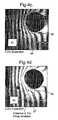
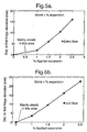
- FIG. 4a, 4b, 4c, 4d and 5a, 5b it can be seen how, for a given type of metal plate having perhaps 3 or 4 diameters of aperture therethrough, a relatively restricted calibration programme can be used to ascertain the amount of cold working (if any) applied to a structural member defining an aperture therethrough of known material and thickness and having a known hole diameter.
- the structural member is a metal plate and the four photographs of Figure 4 show interference carrier fringes 25 having distortions thereto measured to ascertain the amount of cold working in each case. A distance is measured in each case from a point 26 on the periphery of the hole 4 to a position 27 where carrier fringe distortion first occurs.
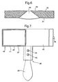
- Figures 6 and 8 may be considered together.
- Figure 6 shows in a sectional view how impact damage 28 can spread from an impacted surface 29 through the thickness of a fibre reinforced plastics composite member 30 to virtually destroy the integrity of the member in the region of the damage 28. It will be noted that the damage is barely visible on the impacted surface 29 but increases dramatically in size towards a rear surface 31.
- Figure 8 is a plan view of an impacted surface 29 of an actual structural member shown photographically.
- Straight interference fringes 32 are shown to be distorted for a considerable distance extending outwardly from an impact damage site 33 of the impacted surface 29.
- the region of distorted interference fringes 34 although visible through the Moiré grating as shown in Figure 8 would be invisible to the naked eye upon inspecting the impacted surface 29.
- Each fringe represents 0.005 in surface displacement.
- the method of the invention therefore provides reliable means to estimate the damage to a composite structure following a barely visible impact to a surface of that structure.
- Calibration curves may be produced relating surface damage area to ultrasonic C scan results to estimate volumetric damage induced through the material thickness using the method of the invention.
- the surface damage area would be ascertained by measuring the area of the distortion of the fringes 34 surrounding the damage site 33.
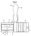
- FIGs 7, 9 and 10 show hand held apparatus 36 according to the invention.
- the apparatus comprises a hollow body 37 of aluminium having a handle 38 carrying two buttons 39, 40.
- the hollow body has a first rectangular hollow tube 41 through which the observer views a surface being inspected via a Moiré grid 8 supported at a lower end 42 thereof.
- the Moiré grid is desirably pivotally mounted to the body 37 and adjustable via a micrometer screw, but this feature is not shown in Figures 7, 9 and 10, but is shown in Figure 2. If such a feature appeared on the embodiment of Figure 7 a lower rectangular frame 43 would be placed flat on the surface being inspected and the angle alpha which the grid would make with that surface would be adjustable with precision via the micrometer adjuster 10 shown in Figure 2. This angle alpha could then be made accurately to reflect the same angle alpha used for calibration purposes.
- a sighting device 44 comprising a needle 45 supported in spaced relationship to a mirror 46.
- a needle 45 supported in spaced relationship to a mirror 46.
- an upper portion 47 of the rectangular tube 41 is tapered to cut out as much extraneous light from the interior of the apparatus as possible. This feature is extremely useful in brightly lit shop floor environments where it would otherwise be difficult accurately to detect the interference fringes viewed through the Moiré grid.
- the apparatus also includes a second rectangular tube 48 set at an angle to the first tube.
- the second tube carries two white 3.6 volt LED light sources 49, 50 acting substantially as point light sources. Buttons 39 and 40 are used individually to switch on the LEDs 49, 50, respectively. It will be observed that LED 49 is designed to shine at an angle of substantially 45° (alpha) to the surface being viewed. LED 50 makes an angle of substantially 63.2° with the said surface.
- the tube 48 also carries a battery pack 51 of three 1.2 volt nickel cadmium cells. The apparatus of the invention is thus totally self-sufficient which makes it particularly suitable for use on the shop floor when, for example, structural members contained in aircraft wings are being viewed.
- holes in structural wing members may be tested for cold expansion and compared with calibration samples of the same material and thickness having known amounts of cold working carried out to them.
- a crack has been detected in a surface of the wing structure it can be determined with accuracy the extent to which any hole from which the crack emanates has been cold worked, and in particular whether it has been cold worked to the specified degree.
- a viewing aperture 52 formed in the top of the tapered portion 47 of the tube 41 can be seen a graticule 53 and an aperture 4 in a surface being viewed.
- the graticule is centred on the aperture. Using the graticule, the distances between points 26 and positions 27 as aforesaid can accurately be read off.
- the apparatus and method of the invention provide convenient and reliable means accurately to obtain measurements of the degree of cold working of holes in metallic structures and impact damage to composite structures.
Landscapes
- Physics & Mathematics (AREA)
- General Physics & Mathematics (AREA)
- Length Measuring Devices By Optical Means (AREA)
- Investigating Strength Of Materials By Application Of Mechanical Stress (AREA)
- Analysing Materials By The Use Of Radiation (AREA)
- Laminated Bodies (AREA)
- Investigating Or Analysing Materials By Optical Means (AREA)
Abstract
Description
Claims (20)
- A method of inspecting the topology of a surface of a structural member to determine the degree to which a known type of stress has been applied to the member, the method including the steps of:providing a range of calibration samples of structurally equivalent members, the samples each having been subject to the known type of stress to a differing respective degree;supporting a Moiré grid in a position spaced from and co-extending with the surface to be inspected and at a small included angle to the surface;directing a source of light through the grid to strike the surface at an oblique angle thereto;viewing the surface through the grid in a direction substantially normal to the surface to view interference fringes and regions of distortion to the fringes, and measuring the extent of a said region of distortion and comparing the said measurement with equivalent measurements taken for respective calibration samples to determine the degree of stress applied to the member.
- A method as in claim 1 in which the step of making the comparison between the said measurement and equivalent distances measured for calibration samples of a member of the same type, relevant dimensions and material, may include determining which sample exhibits substantially the same measured distance as the said member, and noting the degree of stress applied to that sample, which degree of stress will substantially correspond to the stress applied to the said member.
- A method as in claim 1 or 2 including the step of adjusting the small included angle to provide substantially the same fringe density as for the equivalent measurements taken on the calibration samples.
- A method as in claim 1, 2 or 3 including the step of providing a generally parallel said source of light.
- A method as in claim 1, 2 or 3 including the step of providing a substantially point source of said light.
- A method as in any preceding claim in which the step of measuring the extent of a said region of distortion comprises taking the greatest possible measurement across the said region substantially in line with the undistorted fringes, from commencement of distortion on one side of the region to ending of distortion on the other side thereof.
- A method as in any preceding claim in which, where the distortion to the surface comprises an annular region surrounding a hole in the surface, the step of measuring the extent of the region of distortion comprises taking the measurement substantially in line with the undistorted fringes from a periphery of a said hole to a point of fringe distortion farthest from the said periphery.
- A method as in any preceding claim including setting the said oblique angle substantially at one of 45 degrees and 63.2 degrees.
- A method as in any preceding claim including the step of taking a photographic image of the surface as viewed by the observer.
- A method as in claim 9 in which the photographic image is a digitized image and including transferring the digitized image to a computer and image processing same.
- A method as in claim 10 including programming the computer to search for particular shapes of curve representing at least one of commencement and ending of regions of distortion of the fringes.
- Apparatus for carrying out the method of claim 1 including a body supporting:a Moiré grid for placement in a position spaced from and co-extending with the surface to be inspected and at a small included angle to the surface;a source of light directed through the grid to strike the surface at an oblique angle thereto;a viewing aperture for viewing the surface through the grid, and means for measuring the extent of a said region of distortion.
- Apparatus as in claim 12 including a sighting device to enable the observer to determine whether the surface is being viewed substantially normal thereto.
- Apparatus as in claim 13 in which the sighting device includes a mirror facing the observer, the mirror being fast with the body and having a line indicator spaced therefrom in the direction of the observer whereby when the observer views the surface substantially normal thereto no reflection of the line indicator will be observable in the mirror.
- Apparatus as in claim 13 or 14 in which the source of light comprises a light emitting diode.
- Apparatus as in any of claims 13 to 15 in which the camera comprises a high resolution, digital, still camera to photograph the surface.
- Apparatus as in claim 16 including a computer programmed to process a digital image from the camera_and search for particular shapes of curve representing at least one of commencement and ending of regions of distortion of the fringes.
- Apparatus as in any of claims 13 to 17 in which the line spacings of the Moiré grid are substantially in the range 1 to 200 lines per mm.
- Apparatus as in claim 18 in which the said range is substantially 5 to 20 lines per mm.
- Apparatus as in claim 19 in which the said line spacing is substantially 10 lines per mm.
Applications Claiming Priority (3)
| Application Number | Priority Date | Filing Date | Title |
|---|---|---|---|
| GBGB9828474.8A GB9828474D0 (en) | 1998-12-24 | 1998-12-24 | Surface topology inspection |
| GB9828474 | 1998-12-24 | ||
| PCT/GB1999/004385 WO2000039523A1 (en) | 1998-12-24 | 1999-12-20 | Shadow moire surface topology inspection with calibration samples |
Publications (2)
| Publication Number | Publication Date |
|---|---|
| EP1147368A1 EP1147368A1 (en) | 2001-10-24 |
| EP1147368B1 true EP1147368B1 (en) | 2004-10-20 |
Family
ID=10844913
Family Applications (1)
| Application Number | Title | Priority Date | Filing Date |
|---|---|---|---|
| EP99962429A Expired - Lifetime EP1147368B1 (en) | 1998-12-24 | 1999-12-20 | Shadow moire surface topology inspection with calibration samples |
Country Status (10)
| Country | Link |
|---|---|
| US (1) | US6809803B1 (en) |
| EP (1) | EP1147368B1 (en) |
| JP (1) | JP3579356B2 (en) |
| AT (1) | ATE280385T1 (en) |
| AU (1) | AU1878700A (en) |
| CA (1) | CA2356202C (en) |
| DE (1) | DE69921362T2 (en) |
| ES (1) | ES2226480T3 (en) |
| GB (1) | GB9828474D0 (en) |
| WO (1) | WO2000039523A1 (en) |
Families Citing this family (19)
| Publication number | Priority date | Publication date | Assignee | Title |
|---|---|---|---|---|
| JP4090436B2 (en) * | 2002-03-14 | 2008-05-28 | ジュセッペ ペッツォッティ | Stress measuring method and stress measuring apparatus |
| FR2868156B1 (en) | 2004-03-25 | 2006-11-10 | Airbus France Sas | METHOD AND DEVICE FOR NON-DESTRUCTIVE CONTROL OF STRUCTURE STRUCTURE AND CHARACTERIZATION OF THE STRUCTURE DAMAGE BY THE SHADOW MOIRE PRINCIPLE |
| AU2006300008A1 (en) | 2005-10-14 | 2007-04-19 | Applied Research Associates Nz Limited | A method of monitoring a surface feature and apparatus therefor |
| ES2579628T3 (en) | 2009-02-23 | 2016-08-12 | Emergent Virology Llc | Iminoazúcares and methods of treatment of viral diseases |
| EP2400843B1 (en) * | 2009-02-24 | 2015-11-11 | United Therapeutics Corporation | Iminosugars and methods of treating arenaviral infections |
| WO2010144759A1 (en) * | 2009-06-12 | 2010-12-16 | United Therapeutics Corporation | Iminosugars and methods of treating bunyaviral and togaviral diseases |
| CN102595895A (en) | 2009-09-04 | 2012-07-18 | 联合治疗公司 | Imino sugars and methods of treating filoviral diseases |
| JP5575246B2 (en) * | 2009-09-04 | 2014-08-20 | ユナイテッド セラピューティクス コーポレイション | How to treat poxvirus infection |
| EP2473482B1 (en) * | 2009-09-04 | 2014-03-05 | United Therapeutics Corporation | Methods of treating orthomyxoviral infections |
| US9179844B2 (en) | 2011-11-28 | 2015-11-10 | Aranz Healthcare Limited | Handheld skin measuring or monitoring device |
| CA2924026C (en) | 2013-09-16 | 2021-12-28 | Emergent Virology Llc | Deoxynojirimycin derivatives and methods of their using |
| CA2966893C (en) | 2014-11-05 | 2023-10-24 | Emergent Virology Llc | Iminosugars |
| CN104634278A (en) * | 2015-03-03 | 2015-05-20 | 湖北汽车工业学院 | Shadow Moire measuring system for automatic compensation of contrast of fringe pattern |
| US10013527B2 (en) | 2016-05-02 | 2018-07-03 | Aranz Healthcare Limited | Automatically assessing an anatomical surface feature and securely managing information related to the same |
| US11116407B2 (en) | 2016-11-17 | 2021-09-14 | Aranz Healthcare Limited | Anatomical surface assessment methods, devices and systems |
| WO2018185560A2 (en) | 2017-04-04 | 2018-10-11 | Aranz Healthcare Limited | Anatomical surface assessment methods, devices and systems |
| US12039726B2 (en) | 2019-05-20 | 2024-07-16 | Aranz Healthcare Limited | Automated or partially automated anatomical surface assessment methods, devices and systems |
| KR20210153881A (en) * | 2020-06-11 | 2021-12-20 | 서울디엔에스 주식회사 | Measuring apparatus of projection size |
| TWI792621B (en) | 2021-10-20 | 2023-02-11 | 財團法人工業技術研究院 | Measuring method |
Family Cites Families (17)
| Publication number | Priority date | Publication date | Assignee | Title |
|---|---|---|---|---|
| IL63264A (en) | 1980-11-04 | 1986-07-31 | Israel Atomic Energy Comm | Topographical mapping system and method |
| US4489729A (en) * | 1982-09-03 | 1984-12-25 | Medtronic, Inc. | Ultrasound imaging system |
| US4564295A (en) * | 1983-03-07 | 1986-01-14 | New York Institute Of Technology | Apparatus and method for projection moire topography |
| US4697927A (en) * | 1985-11-29 | 1987-10-06 | Kabushiki Kaisha Toshiba | Method and apparatus for measuring a forming error of an object |
| US5016173A (en) * | 1989-04-13 | 1991-05-14 | Vanguard Imaging Ltd. | Apparatus and method for monitoring visually accessible surfaces of the body |
| US5000574A (en) * | 1989-04-20 | 1991-03-19 | The United States Of America As Represented By The Secretary Of The Navy | Interferometric surface distortion detector |
| US5075562A (en) * | 1990-09-20 | 1991-12-24 | Eastman Kodak Company | Method and apparatus for absolute Moire distance measurements using a grating printed on or attached to a surface |
| US5311286A (en) | 1992-04-01 | 1994-05-10 | Materials Technologies Corporation | Apparatus and method for optically measuring a surface |
| US5636025A (en) * | 1992-04-23 | 1997-06-03 | Medar, Inc. | System for optically measuring the surface contour of a part using more fringe techniques |
| US5436462A (en) | 1993-12-21 | 1995-07-25 | United Technologies Optical Systems | Video contour measurement system employing moire interferometry having a beat frequency pattern |
| GB9405457D0 (en) * | 1994-03-19 | 1994-05-04 | British Aerospace | Testing a metal component for cold compression of the metal |
| US5898486A (en) * | 1994-03-25 | 1999-04-27 | International Business Machines Corporation | Portable moire interferometer and corresponding moire interferometric method |
| US5967979A (en) * | 1995-11-14 | 1999-10-19 | Verg, Inc. | Method and apparatus for photogrammetric assessment of biological tissue |
| US5779965A (en) * | 1996-02-20 | 1998-07-14 | Kimberly-Clark Worldwide, Inc. | Double nip embossing |
| US6858826B2 (en) * | 1996-10-25 | 2005-02-22 | Waveworx Inc. | Method and apparatus for scanning three-dimensional objects |
| GB2326228B (en) | 1997-06-10 | 2000-05-24 | British Aerospace | Non-contact deformation measurement |
| US6731391B1 (en) * | 1998-05-13 | 2004-05-04 | The Research Foundation Of State University Of New York | Shadow moire surface measurement using Talbot effect |
-
1998
- 1998-12-24 GB GBGB9828474.8A patent/GB9828474D0/en not_active Ceased
-
1999
- 1999-12-20 WO PCT/GB1999/004385 patent/WO2000039523A1/en not_active Ceased
- 1999-12-20 CA CA002356202A patent/CA2356202C/en not_active Expired - Fee Related
- 1999-12-20 JP JP2000591378A patent/JP3579356B2/en not_active Expired - Fee Related
- 1999-12-20 ES ES99962429T patent/ES2226480T3/en not_active Expired - Lifetime
- 1999-12-20 EP EP99962429A patent/EP1147368B1/en not_active Expired - Lifetime
- 1999-12-20 AU AU18787/00A patent/AU1878700A/en not_active Abandoned
- 1999-12-20 DE DE69921362T patent/DE69921362T2/en not_active Expired - Lifetime
- 1999-12-20 US US09/466,899 patent/US6809803B1/en not_active Expired - Fee Related
- 1999-12-20 AT AT99962429T patent/ATE280385T1/en not_active IP Right Cessation
Also Published As
| Publication number | Publication date |
|---|---|
| CA2356202A1 (en) | 2000-07-06 |
| JP3579356B2 (en) | 2004-10-20 |
| JP2002533702A (en) | 2002-10-08 |
| DE69921362D1 (en) | 2004-11-25 |
| CA2356202C (en) | 2005-07-26 |
| WO2000039523A1 (en) | 2000-07-06 |
| US6809803B1 (en) | 2004-10-26 |
| GB9828474D0 (en) | 1999-02-17 |
| ATE280385T1 (en) | 2004-11-15 |
| ES2226480T3 (en) | 2005-03-16 |
| EP1147368A1 (en) | 2001-10-24 |
| AU1878700A (en) | 2000-07-31 |
| DE69921362T2 (en) | 2005-02-24 |
Similar Documents
| Publication | Publication Date | Title |
|---|---|---|
| CA2356202C (en) | Shadow moire surface topology inspection with calibration samples | |
| CN102713582B (en) | Inclusion Detection in Polished Gemstones | |
| US4378701A (en) | Apparatus and method for indicating stress in an object | |
| US20030223054A1 (en) | Method and apparatus for identifying gemstones | |
| CN102077052A (en) | Vision System for Scan Planning for Ultrasound Exams | |
| US7193694B2 (en) | Method for grading gemstone cut and symmetry | |
| JP2001099632A (en) | Specular reflection type surface texture measuring method and device using CCD camera | |
| Reynolds et al. | Theory and applications of a surface inspection technique using double-pass retroreflection | |
| JP2004004088A (en) | Method and apparatus for measuring the surface profile of an object | |
| US11579008B1 (en) | Estimating gemstone weight in mounted settings | |
| WO2009133393A1 (en) | Locating inclusions in diamond | |
| AU2005248493A1 (en) | Inspection of wood surface roughness | |
| JP3646063B2 (en) | Apparatus for detecting and measuring small periodic undulations on technical surfaces | |
| JPH06281593A (en) | Surface inspection method and apparatus | |
| JP2004163129A (en) | Defect inspection method | |
| US7570369B2 (en) | Method and a device for measurement of edges | |
| Hathaway et al. | Residual stress evaluation using shearography with large-shear displacements | |
| JPS60228943A (en) | Inspection of surface state of stainless steel plate | |
| KR101180247B1 (en) | Micro-structure measurement device using diffraction of laser | |
| JPH08159878A (en) | Illumination device | |
| WO2005103608A1 (en) | Continuous surface deformation measurement | |
| Roos | Hailstone size inferred from dents in cold-rolled aluminum sheet | |
| Amin et al. | A transmission replica system for strain measurement | |
| Baker | Optical instrumentation for quality assurance | |
| Kotanen et al. | Evaluation of Shadow Moire for surface deformation detection and measurement |
Legal Events
| Date | Code | Title | Description |
|---|---|---|---|
| PUAI | Public reference made under article 153(3) epc to a published international application that has entered the european phase |
Free format text: ORIGINAL CODE: 0009012 |
|
| 17P | Request for examination filed |
Effective date: 20010625 |
|
| AK | Designated contracting states |
Kind code of ref document: A1 Designated state(s): AT BE CH CY DE DK ES FI FR GB GR IE IT LI LU MC NL PT SE |
|
| AX | Request for extension of the european patent |
Free format text: AL;LT;LV;MK;RO;SI |
|
| RAP1 | Party data changed (applicant data changed or rights of an application transferred) |
Owner name: AIRBUS UK LIMITED |
|
| GRAP | Despatch of communication of intention to grant a patent |
Free format text: ORIGINAL CODE: EPIDOSNIGR1 |
|
| GRAS | Grant fee paid |
Free format text: ORIGINAL CODE: EPIDOSNIGR3 |
|
| GRAA | (expected) grant |
Free format text: ORIGINAL CODE: 0009210 |
|
| AK | Designated contracting states |
Kind code of ref document: B1 Designated state(s): AT BE CH CY DE DK ES FI FR GB GR IE IT LI LU MC NL PT SE |
|
| PG25 | Lapsed in a contracting state [announced via postgrant information from national office to epo] |
Ref country code: SE Free format text: LAPSE BECAUSE OF FAILURE TO SUBMIT A TRANSLATION OF THE DESCRIPTION OR TO PAY THE FEE WITHIN THE PRESCRIBED TIME-LIMIT Effective date: 20041020 Ref country code: LI Free format text: LAPSE BECAUSE OF FAILURE TO SUBMIT A TRANSLATION OF THE DESCRIPTION OR TO PAY THE FEE WITHIN THE PRESCRIBED TIME-LIMIT Effective date: 20041020 Ref country code: FI Free format text: LAPSE BECAUSE OF FAILURE TO SUBMIT A TRANSLATION OF THE DESCRIPTION OR TO PAY THE FEE WITHIN THE PRESCRIBED TIME-LIMIT Effective date: 20041020 Ref country code: CY Free format text: LAPSE BECAUSE OF FAILURE TO SUBMIT A TRANSLATION OF THE DESCRIPTION OR TO PAY THE FEE WITHIN THE PRESCRIBED TIME-LIMIT Effective date: 20041020 Ref country code: CH Free format text: LAPSE BECAUSE OF FAILURE TO SUBMIT A TRANSLATION OF THE DESCRIPTION OR TO PAY THE FEE WITHIN THE PRESCRIBED TIME-LIMIT Effective date: 20041020 Ref country code: AT Free format text: LAPSE BECAUSE OF FAILURE TO SUBMIT A TRANSLATION OF THE DESCRIPTION OR TO PAY THE FEE WITHIN THE PRESCRIBED TIME-LIMIT Effective date: 20041020 |
|
| REG | Reference to a national code |
Ref country code: GB Ref legal event code: FG4D |
|
| REG | Reference to a national code |
Ref country code: CH Ref legal event code: EP |
|
| REG | Reference to a national code |
Ref country code: IE Ref legal event code: FG4D |
|
| REF | Corresponds to: |
Ref document number: 69921362 Country of ref document: DE Date of ref document: 20041125 Kind code of ref document: P |
|
| PG25 | Lapsed in a contracting state [announced via postgrant information from national office to epo] |
Ref country code: LU Free format text: LAPSE BECAUSE OF NON-PAYMENT OF DUE FEES Effective date: 20041220 Ref country code: IE Free format text: LAPSE BECAUSE OF NON-PAYMENT OF DUE FEES Effective date: 20041220 |
|
| PG25 | Lapsed in a contracting state [announced via postgrant information from national office to epo] |
Ref country code: MC Free format text: LAPSE BECAUSE OF NON-PAYMENT OF DUE FEES Effective date: 20041231 |
|
| PG25 | Lapsed in a contracting state [announced via postgrant information from national office to epo] |
Ref country code: GR Free format text: LAPSE BECAUSE OF FAILURE TO SUBMIT A TRANSLATION OF THE DESCRIPTION OR TO PAY THE FEE WITHIN THE PRESCRIBED TIME-LIMIT Effective date: 20050120 Ref country code: DK Free format text: LAPSE BECAUSE OF FAILURE TO SUBMIT A TRANSLATION OF THE DESCRIPTION OR TO PAY THE FEE WITHIN THE PRESCRIBED TIME-LIMIT Effective date: 20050120 |
|
| REG | Reference to a national code |
Ref country code: ES Ref legal event code: FG2A Ref document number: 2226480 Country of ref document: ES Kind code of ref document: T3 |
|
| REG | Reference to a national code |
Ref country code: CH Ref legal event code: PL |
|
| PLBE | No opposition filed within time limit |
Free format text: ORIGINAL CODE: 0009261 |
|
| STAA | Information on the status of an ep patent application or granted ep patent |
Free format text: STATUS: NO OPPOSITION FILED WITHIN TIME LIMIT |
|
| REG | Reference to a national code |
Ref country code: IE Ref legal event code: MM4A |
|
| 26N | No opposition filed |
Effective date: 20050721 |
|
| ET | Fr: translation filed | ||
| PG25 | Lapsed in a contracting state [announced via postgrant information from national office to epo] |
Ref country code: PT Free format text: LAPSE BECAUSE OF NON-PAYMENT OF DUE FEES Effective date: 20050320 |
|
| PGFP | Annual fee paid to national office [announced via postgrant information from national office to epo] |
Ref country code: ES Payment date: 20091222 Year of fee payment: 11 |
|
| PGFP | Annual fee paid to national office [announced via postgrant information from national office to epo] |
Ref country code: NL Payment date: 20091222 Year of fee payment: 11 |
|
| PGFP | Annual fee paid to national office [announced via postgrant information from national office to epo] |
Ref country code: IT Payment date: 20091222 Year of fee payment: 11 |
|
| PGFP | Annual fee paid to national office [announced via postgrant information from national office to epo] |
Ref country code: BE Payment date: 20100212 Year of fee payment: 11 |
|
| BERE | Be: lapsed |
Owner name: *AIRBUS UK LTD Effective date: 20101231 |
|
| REG | Reference to a national code |
Ref country code: NL Ref legal event code: V1 Effective date: 20110701 |
|
| REG | Reference to a national code |
Ref country code: FR Ref legal event code: CD |
|
| PG25 | Lapsed in a contracting state [announced via postgrant information from national office to epo] |
Ref country code: BE Free format text: LAPSE BECAUSE OF NON-PAYMENT OF DUE FEES Effective date: 20101231 |
|
| REG | Reference to a national code |
Ref country code: DE Ref legal event code: R082 Ref document number: 69921362 Country of ref document: DE Representative=s name: PATENTANWAELTE WALLACH, KOCH & PARTNER, DE |
|
| PG25 | Lapsed in a contracting state [announced via postgrant information from national office to epo] |
Ref country code: NL Free format text: LAPSE BECAUSE OF NON-PAYMENT OF DUE FEES Effective date: 20110701 Ref country code: IT Free format text: LAPSE BECAUSE OF NON-PAYMENT OF DUE FEES Effective date: 20101220 |
|
| REG | Reference to a national code |
Ref country code: DE Ref legal event code: R082 Ref document number: 69921362 Country of ref document: DE Representative=s name: PATENTANWAELTE WALLACH, KOCH, DR. HAIBACH, FEL, DE Effective date: 20111207 Ref country code: DE Ref legal event code: R082 Ref document number: 69921362 Country of ref document: DE Representative=s name: PATENTANWAELTE WALLACH, KOCH & PARTNER, DE Effective date: 20111207 Ref country code: DE Ref legal event code: R081 Ref document number: 69921362 Country of ref document: DE Owner name: AIRBUS OPERATIONS LIMITED, GB Free format text: FORMER OWNER: AIRBUS UK LTD., FILTON, GB Effective date: 20111207 Ref country code: DE Ref legal event code: R081 Ref document number: 69921362 Country of ref document: DE Owner name: AIRBUS OPERATIONS LIMITED, FILTON, GB Free format text: FORMER OWNER: AIRBUS UK LTD., FILTON, BRISTOL, GB Effective date: 20111207 |
|
| REG | Reference to a national code |
Ref country code: ES Ref legal event code: FD2A Effective date: 20120206 |
|
| PG25 | Lapsed in a contracting state [announced via postgrant information from national office to epo] |
Ref country code: ES Free format text: LAPSE BECAUSE OF NON-PAYMENT OF DUE FEES Effective date: 20101221 |
|
| REG | Reference to a national code |
Ref country code: FR Ref legal event code: PLFP Year of fee payment: 17 |
|
| PGFP | Annual fee paid to national office [announced via postgrant information from national office to epo] |
Ref country code: DE Payment date: 20151211 Year of fee payment: 17 Ref country code: GB Payment date: 20151221 Year of fee payment: 17 |
|
| PGFP | Annual fee paid to national office [announced via postgrant information from national office to epo] |
Ref country code: FR Payment date: 20151221 Year of fee payment: 17 |
|
| REG | Reference to a national code |
Ref country code: DE Ref legal event code: R119 Ref document number: 69921362 Country of ref document: DE |
|
| GBPC | Gb: european patent ceased through non-payment of renewal fee |
Effective date: 20161220 |
|
| REG | Reference to a national code |
Ref country code: FR Ref legal event code: ST Effective date: 20170831 |
|
| PG25 | Lapsed in a contracting state [announced via postgrant information from national office to epo] |
Ref country code: FR Free format text: LAPSE BECAUSE OF NON-PAYMENT OF DUE FEES Effective date: 20170102 |
|
| PG25 | Lapsed in a contracting state [announced via postgrant information from national office to epo] |
Ref country code: DE Free format text: LAPSE BECAUSE OF NON-PAYMENT OF DUE FEES Effective date: 20170701 Ref country code: GB Free format text: LAPSE BECAUSE OF NON-PAYMENT OF DUE FEES Effective date: 20161220 |